EP3103331A1 - Fer à cheval et procédé de ferrage d'un sabot - Google Patents
Fer à cheval et procédé de ferrage d'un sabot Download PDFInfo
- Publication number
- EP3103331A1 EP3103331A1 EP15171664.4A EP15171664A EP3103331A1 EP 3103331 A1 EP3103331 A1 EP 3103331A1 EP 15171664 A EP15171664 A EP 15171664A EP 3103331 A1 EP3103331 A1 EP 3103331A1
- Authority
- EP
- European Patent Office
- Prior art keywords
- base plate
- fitting
- hoof
- elevator
- wall
- Prior art date
- Legal status (The legal status is an assumption and is not a legal conclusion. Google has not performed a legal analysis and makes no representation as to the accuracy of the status listed.)
- Granted
Links
Images



Classifications
-
- A—HUMAN NECESSITIES
- A01—AGRICULTURE; FORESTRY; ANIMAL HUSBANDRY; HUNTING; TRAPPING; FISHING
- A01L—SHOEING OF ANIMALS
- A01L3/00—Horseshoes fastened by means other than nails, with or without additional fastening by nailing
-
- A—HUMAN NECESSITIES
- A01—AGRICULTURE; FORESTRY; ANIMAL HUSBANDRY; HUNTING; TRAPPING; FISHING
- A01L—SHOEING OF ANIMALS
- A01L5/00—Horseshoes made of elastic materials
Definitions
- the invention relates to a fitting for a hoof of an equid, e.g. of a horse, and a method for fogging a hoof of an equid, e.g. a horse, with a fitting or a temporary attachment of a fitting.
- the outer horny layers can be attacked in the long term, which are associated with similar disadvantages as when nailing. Furthermore, the adhesive technique is associated with relatively high costs, is very time consuming and requires a lot of expertise in the implementation.
- adhesive e.g. Epoxyl resin adhesives
- the object of the present invention may therefore be to provide a fitting for a hoof of an equid, e.g. of a horse, and a method for fogging a hoof of an equid, e.g. a horse to provide, which allow a quick, easy and gentle to the horse misting and changing the fitting without having to renew the connection of the fitting to the hoof during a fitting period, if there is a need to remove the fitting and attach again.
- the fitting according to the invention for a hoof of an equid, for example a horse comprises a base plate and at least one elevator.
- the base plate is connected to the at least one elevator.
- the at least one elevator has hoof wall attachment means which are adapted to reversibly releasably attach the at least one elevator to a hoof wall of the equine, for example the horse.
- the fitting according to the invention is a modular system which comprises the modules base plate and elevator or lifts and.
- the modular system allows a user to attach the fitting to the hoof wall of a horse in a targeted and sensible way, often during a fitting period, and to detach it from the hoof wall again.
- the modular system makes it possible to change a shoe on a horse, without having to renew a connection between the shoe and hoof wall of the horse during a fitting period. This saves time, is easy and spares the horse to be reared.
- the modular system allows the fitting to be adjusted individually to the existing hoof conditions.
- the baseplate is preferably adapted to a previously professionally prepared hoof and may further have a shape which is modeled on the lower cross section of a hoof to be studded, the outer edges being along the outer lower edges of a hoof wall (sidewalls of the hoof) and in the heel area of the hoof a little bit overhanging.
- a particularly preferred embodiment of the elevator or lifts (2-leaf front elevator of the toe wall) allows positioning of the hoof in the fitting in which the toe wall of the hoof can extend beyond the fitting. This positioning supports the hoof's natural roll-off point on the ground.
- the at least one elevator is shaped and adapted to be secured to the baseplate and hoof wall so that the shoeing of the horse's hoof can fit the hoof form and the hoof of the horse is therefore fogged.
- the at least one elevator may for example be formed by a fastening tab, the fastening tab having attachment surfaces for attaching the hoof wall attachment means and attachment surfaces for further attachment means for connection to the base plate, e.g. Means for latching.
- the at least one elevator can be specifically provided at positions which are relevant for a secure hold of the fitting.
- the connection between the at least one elevator and the baseplate can be made, for example, by each part of the at least one elevator running around an edge of the baseplate and fixed to the underside of the baseplate, e.g. by clicking into a special profile.
- the underside of the base plate means that side which faces away from the horse's hoof when the fitting is attached to the horse's hoof and the horse is therefore misted.
- the hoof wall fasteners fall e.g. Two-piece closure mechanisms, each one of the two parts is arranged on one of the elements to be connected, in this case on the at least one elevator and the hoof wall of the horse to be beaten.
- the hoof wall fasteners fall e.g. Velcro fasteners, snap fasteners or click fasteners. That the elevator or elevators can be reversibly releasably connected to the hoof wall, means that a temporary connection can be made, which is useful and as often as possible during a fitting period solvable without destroying the connection.
- the fitting according to the invention allows a particularly quick and easy handling.
- the shoeing can be useful changed often during a fitting period, without having to renew the connection between the fitting and hoof wall of the horse.
- the burden on the hoof wall of the horse can be kept particularly low.
- the entire fitting can be removed / attached and re-attached / removed in a particularly short time.
- the base plate on application fastening means which are adapted to fix an application reversibly releasably attached to the base plate.
- the applications can also be permanently attached to the Base plate to be attached. It can also be several different applications attached to the base plate in this way.
- the applications mentioned are those which are of orthopedic useful nature, for example damping plastic elements in horseshoe shape or jet-supporting cushions.
- applications of a very wide variety of materials for example made of plastic or of materials which do not cause punctiform pressure, and of the most varied forms, eg in horseshoe shape, can be attached to the modular system as often and particularly easily as possible and again separated therefrom.
- the application fastening means include, for example, two-part closure mechanisms, one of the two parts being arranged on one of the elements to be connected, in this case on the application and on the base plate.
- the hoof-fitting fasteners include, for example, hook-and-loop fasteners, snap fasteners or click fasteners. That the application can be reversibly detachably connected to the base plate, means that a temporary connection can be made, which is useful often solvable during a fitting period, without destroying the connection.
- the application fastening means are arranged on the base plate in such a way that the application can be positioned on a suitable place for the hoof of the horse.
- the application fastening means can furthermore be designed and positioned in such a way that applications of different shapes can be fastened to the base plate and thus also to the hoof of the horse to be studed.
- the hoof-wall fastening means comprise a part of a hook-and-loop fastener, a snap-in fastener or a click fastener.
- Another part or a counterpart of the hook-and-loop fastener, the snap-in fastener or the click fastener can be attached to the hoof wall of the horse to be studded, so that the elevator or the lifts can be reversibly detachably attached to the hoof wall by means of the hook-and-loop fastener of the snap-in fastener or click fastener can be attached.
- a first hook-and-loop strip may be coated with a self-adhesive tape which attaches to the hoof wall at positions where there is a connection between the elevator (s) and the hoof wall.
- a second Velcro strip which to is adapted to be reversibly releasably connected to the first Velcro strip may also be coated in a similar manner with a self-adhesive tape which is attached to the elevator or the lifts such that the first Velcro strips and the second Velcro strips can be interconnected.
- the application fastening means comprise part of a click closure.
- Another part or a counterpart of the click fastener can be attached to the application, so that the application can be reversibly releasably secured to the base plate by means of the click fastener. If the weight of the horse on the hoof and thus also on the application and the base plate of the fitting loads, then the weight of the horse strengthens the cohesion of the click connection between the application and the base plate.
- a click closure is to be understood as meaning, in particular, a non-destructively releasable positive locking of two elements, one of the elements being connected to one of the parts to be joined, e.g. the hoof wall and the at least one elevator or an application and the base plate. The force required to release the positive engagement is not achieved by the stresses that occur during normal movements of the horse.
- hook-and-loop fasteners, snap-fasteners and click fasteners are cost-effective quick-release fasteners and allow a sufficiently firm and simple attachment of the elevator or lifts on a hoof wall or a removal of the lifts from a hoof wall.
- these embodiments make a contribution to be able to change a hoof fitting for a horse very quickly, easily, structurally friendly and cost-effective.
- the elevators have a substantially angular cross section, wherein in each case at least one hoof wall leg of the elevators is adapted for attachment to the hoof wall of the horse and in each case at least one base plate legs of the elevators is adapted for attachment to the base plate.
- the elevators are so flexible that they can easily be moved away from the hoof wall in order, for example. to solve a Velcro connection.
- the profile of the elevators may, for example, have a substantially L-shaped cross section, the hoof wall legs each being parallel to the hoof wall of a horse to be studded and the base plate legs each being parallel to the base plate.
- the fitting may comprise three elevators, wherein a first elevator is disposed at a left edge portion of the base plate, a second elevator is disposed at a right edge portion of the base plate, and a third elevator is disposed at a front edge portion of the base plate.
- the front edge portion here is that edge portion of the base plate, which is arranged in the region of a toe of a hoof, when the fitting is fixed as intended on the hoof of a horse.
- the third elevator which is arranged on the front edge portion of the base plate having two Hufwand legs so spaced apart that a front toe area of the horse's hoof is at least partially kept free when the fitting on the hoof wall of the horse attached and the hoof of the horse is fogged thus.
- a total of five elevators can advantageously be provided, which can be distributed around the edge of the base plate such that by phasing of the lifts (seen from below) a facilitated unrolling of the hoof is made possible.
- the elevator or the elevators each have at least one notch in the region of a connection to the base plate.
- two laterally juxtaposed notches are provided in the base plate leg of the at least one elevator, wherein the notches are arranged adjacent to the hoof wall leg of the at least one elevator.
- the at least one Notching causes the baseplate leg of the at least one elevator to extend laterally particularly well under tensile or thrust loading, in an elastic manner.
- the fixed connection between the base plate and the elevator or the lifts is reversibly detachable. This makes a further contribution to build the mounting system in a modular manner, with particularly flexible to replace lifts, removed or added.
- the base plate preferably has the at least one elevator or, for each of the elevators, a shaft for receiving the lift or elevators in regions, the respective shaft and the respective elevator being designed to be reversibly detachably connected to one another.
- the base plate legs of the elevators can be inserted into the shafts of the base plate, wherein the base plate legs can engage in the slots of the base plate and such a latch is adapted to be repealed without destruction.
- a free end of the base plate leg may be shaped such that it does not contact a wall surface of the shaft to allow the insertion of a tool for releasing the locking between the base plate leg and shaft and for pushing the base plate leg out of the shaft.
- the cross section of the base plate leg tapers towards its open end, whereas the wall forming walls of the base plate parallel to each other, whereby a wedge-shaped space between the walls of the shaft and the base plate legs, in which a particularly wedge-shaped tool can be introduced particularly advantageous.
- a particularly elastic jet support is attached to the base plate for generating a counter-pressure on a beam of the hoof of a horse to be beaten.
- the jet support is preferably adapted to generate a variably adjustable backpressure depending on the selected height of a jet pad used on the beam. This promotes beam growth by exerted pressure stimulus.
- the jet support is an application and is preferably mounted between the open ends of the hoof wall in the rear region of the base plate and is offset from the base plate vertically in the direction of the hoof to be beaten.
- the jet assist stimulates the return of blood flow to the heart, as well as the distribution of lymphatic fluid in the horse's body, which is beneficial to the health of the horse to be studded.
- the jet support may also be reversibly releasably secured to the baseplate, e.g. by means of a click closure as explained above in connection with the connection between the application or the applications and the base plate.
- the base plate and the elevator or the lifts can continue to be made of a plastic.
- the base plate can stabilize an ironing element, z.b. made of carbon, be introduced.
- the fitting is particularly easy.
- the hoof and joints of a horse to be studded are thus spared by the high damping and low distortion factor inherent in the plastic.
- the base plate has a U-shaped stiffening element for stiffening the base plate.
- the stiffening element can counteract a bending of the fitting.
- the stiffening element can be made of a fiber-reinforced plastic, eg carbon, which in particular weight can be saved.
- a carbon stiffening element allows for vertical movement of the hoof walls, which is particularly advantageous for a healthy and functioning hoof mechanism.
- the stiffening element can be anchored in particular in the base plate.
- the materials used are in particular those with high rigidity, for example metals, with lighter metals, for example aluminum-in order to save weight-in comparison to heavier metals, for example iron, being particularly advantageous.
- the stiffening element may also have shafts for receiving the elevators if it is to be positioned at the same height as the shafts in the base plate, for example to reduce the thickness of the fitting.
- the U-shape of the stiffening element can also be broken, for example in the form of two or more leg portions of a U-shape, but without connection to each other.
- the base plate is horseshoe-shaped and made of fiber-reinforced plastic, e.g. Carbon, manufactured.
- the base plate may also be made of iron, another plastic or another metal, e.g. Aluminum, be made. It is essential that the base plate by their material has a particularly high rigidity, without the need for additional stiffening elements.
- the base plate is particularly material-saving, thereby saving weight and costs.
- the open ended ends of the horseshoe-shaped base plate may be replaced by a bridge element, e.g. made of a plastic material, are joined together, wherein on the bridge element - in particular reversibly detachable - applications such as the beam support described above can be attached.
- click connections for clicking on other applications for the fitting can be arranged on the base plate.
- the shafts for receiving the elevators may be incorporated directly, or indentations or apertures on the floor-facing side may be left out to click on a lift or elevators.
- a previously described one is described above provided according to the invention fitting.
- a base plate of such a fitting was previously adapted to the hoof of the equid and then attached at least one elevator to the adapted base plate.
- counterparts to hoof wall fasteners of the at least one elevator are attached to the hoof wall of the equid.
- a reversibly releasable attachment of the at least one elevator takes place on the hoof wall of the equid by means of the hoof wall fastening means.
- the method steps may advantageously be additionally followed, according to which a reversible release of the fastening of the at least one elevator from the hoof wall and a reversible release of the fastening of the application or the applications from the base plate takes place.
- a previously attached to the base plate at least one application which was attached by attaching the lifts on the hoof wall and the hoof of the horse to be beaten, again from the hoof and possibly.
- another application as described above can be reversibly detachably attached to the base plate by means of the application fastening means.
- This embodiment thus enables a particularly fast, easy and gentle for the horse replacement of an application or an elevator of a horseshoe.
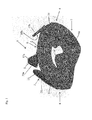
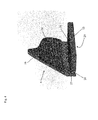
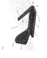
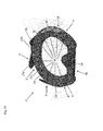
- Fig. 1 to 5 show a fitting 1, which comprises a base plate 2 made of a plastic material and three lifts 3 to 5, which are also made of a plastic material.
- the base plate 2 is fixedly connected to the elevators 3 to 5, wherein a first elevator 3 at a left edge portion 6 of the base plate second is arranged, a second elevator 4 is arranged at a right edge portion 7 of the base plate 2 and a third elevator 5 is arranged at a front edge portion 8 of the base plate 2.
- the base plate 2 for each of the elevators 3 to 5 a shaft 9 to 11 for fixed areawise recording of the elevators 3 to 5, wherein the respective shaft 9 to 11 and elevator 3 to 5 are arranged to reversibly releasably connected to each other become.
- the elevators 3 to 5 each have a substantially angular cross section, in the example shown a substantially L-shaped cross-section, wherein each hoof wall legs 15, 16, 17 a and 17 b of the elevators 3 to 5 for attachment to a through Fig. 7 shown hoof wall 32 a through Fig. 6 shown equestrian 30 is arranged and in each case at least one base plate legs 12 to 14 of the respective elevators 3 to 5 is arranged for attachment to the base plate 2.
- the third elevator 5, which is arranged on the front edge portion 8 of the base plate 2, in this case has two hoof wall legs 17 a and 17 b, which are spaced apart such that a through Fig.
- the hoof wall legs 17a, 17b can also be combined to form a single hoof wall leg, in which case the entire toe area is enclosed.
- the base plates legs 12 to 14 comprise structured surfaces 18 to 23 with teeth facing in a common direction.
- the surfaces of the wells 9 to 11 also have unshown teeth which are oriented in the opposite direction as the teeth of the base plate legs 12 to 14.
- the base plate legs 12 to 14 have sufficient material thickness to be pressed under pressure the shafts 9 to 11 can be inserted and under normal conditions of use of the fitting 1 does not slip out of the shafts 9 to 11, since the teeth of the base plate legs 12 to 14 can engage in the teeth of the surfaces of the shafts 9 to 11 ( see in particular Fig. 4 for the second elevator and 5 for the third elevator).
- the base plate legs 12 to 14 By applying a sufficient tensile force or by prior introduction of wedge or push elements not shown a tool and a sufficient pressure force the base plate legs 12 to 14, however, can be pulled out of the wells 9 to 11, which in the normal use of the fitting 1 fixed, but reversibly releasable connection between the base plate 2 and the lifts 3 to 5 is provided.
- the base plate legs 12 to 14 also each have two notches 24 to 29, which allow under tensile load an elastic lateral extent of the base plate legs 12 to 14.
- the base plate 2 further comprises application fasteners in the form of apertures 30 as part of a click fastener which is adapted for reversibly releasable attachment of orthopedic applications, e.g. are arranged in the form of a horseshoe 31 of a damping plastic material on the base plate 2.
- a plastic sole protecting the entire sole can be clicked on.
- Counterparts to the openings 30 are arranged on the horseshoe 31 in the form of mushroom heads 30 '.
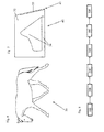
- FIG. 6 and 7 show a horse 30, at the hooves 40 of the fitting 1 after Fig. 1 to 5 such as Fig. 9 and Fig. 10 can be attached.
- Fig. 7 shows only schematically and not to scale the hoof wall 32 of the horse 30 after Fig. 6 ,
- the hoof-wall legs 15, 16, 17a and 17b of the hoists 3 to 5 have hoof-wall fastening means in the form of self-adhesive tape-glued parts 33, 34, 35a and 35b of hook-and-loop fasteners for reversibly releasably securing the hoof-wall legs 15, 16, 17a and 17b of the elevators 3 to 5 are arranged on the hoof wall 32 of the horse 30.
- mating counterparts 36 and 37 are adhered to the parts of the hook and loop fastener mechanisms 33, 34, 35a and 35b by self-adhesive tapes (see FIG. Fig. 7 ), where in Fig. 7 only two counterparts 36 and 37 are shown due to the side view.
- a jet support 38 for generating a variable back pressure on a beam of the hoof 40 of the horse to be studed 30 on the base plate 2 by means of another click closure reversible as the horseshoe-shaped, shock-absorbing application 31 is attached to the base plate 2.
- a U-shaped stiffening element 39 for stiffening the base plate 2 is arranged within the base plate 2, wherein the stiffening element 39 is anchored in the base plate 2. This stabilizing stiffening element 39 allows vertical movements of the lateral hoof walls in the sense of a positive hoof mechanism.
- Fig. 8 shows the sequence of the method steps of a method according to the invention for fogging the horse 30 after Fig. 6 with a fitting 1 according to Fig. 1
- a fitting 1 is after Fig. 1 provided, wherein the base plate 2 has previously been adapted to the hoof 40 of the horse 30, and wherein the elevators 3 to 5 have been attached to the hoof 40 of the horse 30 on the base plate 2 after fitting the base plate 2.
- attachment of counterparts 36, 37 to the hoof wall fastening means 33, 34, 35a, 35b of the elevators 3 to 5 takes place on the hoof wall 32 of the horse 30.
- a further method step 200 ' the applications 31 and 38 by means of the openings 30 and the mushroom heads 30' on the base plate 2 of the fitting 1 are reversibly releasably attached.
- a third method step 300 a reversibly releasable fastening of the elevators 3 to 5 of the fitting 1 on the hoof wall 32 of the horse 30 by means of the parts of the Velcro fasteners, which on the hoof wall legs 15, 16, 17 a and 17 b and on the hoof wall 32nd are attached.
- the fitting 1 is attached to the hoof wall 32 of the horse 30 and the shock-absorbing application in the form of the horseshoe 31 and the beam support 38 are located at the intended positions on the hoof 40 of the horse 30.
- the hoof 40 of the horse 30 is thus misted.
- the fitting 1 is detached from the hoof wall 32 of the horse 30.
- the hoof 40 of the horse 30 is thus no longer fogged.
- the steps 100 and 300 are repeated with another base plate 2.
- Fig. 9 shows a further fitting 1, which comprises a horseshoe-shaped base plate 2, for example made of carbon and three lifts 3 to 5, which are made of a plastic material.
- the base plate 2 is fixedly connected to the elevators 3 to 5, wherein a first elevator 3 is arranged on a left edge portion 6 of the base plate 2, a second elevator 4 is arranged on a right edge portion 7 of the base plate 2 and a third elevator 5 on a front edge portion 8 of the base plate 2 is arranged.
- the base plate 2 has, for each of the elevators 3 to 5, a shaft for fixed area-wise accommodation of the elevators 3 to 5, wherein the respective shaft and elevator 3 to 5 are arranged to be reversibly detachably connected to each other, as described above with the shafts 9 to 11 and the lifts 3 to 5 of the fitting 1 to Fig. 1 to 5 is described.
- the elevators 3 to 5 each have a substantially angular cross-section, in the example shown a substantially L-shaped cross-section, each with a hoof wall legs 15, 16, 17 a and 17 b of the elevators 3 to 5 for attachment to the through Fig. 7 shown hoof wall 32 of Fig. 6 horse shown 30 is set up and in each case at least one base plate legs 12 to 14 of the respective elevators 3 to 5 is arranged for attachment to the base plate 2 by inserting into the shafts thereof.
- the third elevator 5, which is arranged at the front edge portion 8 of the base plate 2, in this case has two hoof wall legs 17 a and 17 b, which are spaced apart from each other such that the through Fig.
- the base plate legs 12 to 14 may further each have two not shown notches (see the similar notches 24 to 29 according to Fig. 2 . 4 and 5 ), which allow under tensile load an elastic lateral extension of the horseshoe legs 12 to 14.
- the hoof wall legs 15, 16, 17a and 17b of the elevators 3 to 5 further comprise hoop wall fastening means in the form of adhesive-bonded by means of adhesive strips adhered parts 33, 34, 35a and 35b of Velcro fasteners, which for reversibly releasable attachment of the hoof wall legs 15th , 16, 17a and 17b of the elevators 3 to 5 are arranged on the hoof wall 32 of the horse 30.
- hoop wall fastening means in the form of adhesive-bonded by means of adhesive strips adhered parts 33, 34, 35a and 35b of Velcro fasteners, which for reversibly releasable attachment of the hoof wall legs 15th , 16, 17a and 17b of the elevators 3 to 5 are arranged on the hoof wall 32 of the horse 30.
- matching counterparts 36 and 37 are glued to the parts of the hook and loop fasteners 33, 34, 35a and 35b by means of self-adhesive strips (cf. Fig. 7 ), where
- the open-ended ends of the base plate 2 are connected to each other by a bridge element 42, whereby the rigidity of the base plate 2 and thus of the fitting 1 is increased. Furthermore, a jet support 38 for generating a back pressure on a beam of the hoof 40 of the horse 30 to be studed is attached to the bridge element 42 by means of further click bonds 43 reversibly releasably. On a stiffening element 39 - as by Fig. 3 shown - can be omitted in this embodiment.
- the through Fig. 10 Fitting 1 shown differs from the one shown Fig. 9 in that additional click connection elements 44 are provided on the base plate 2, which enable clicking on other applications on the hoof fitting 31.
Landscapes
- Life Sciences & Earth Sciences (AREA)
- Engineering & Computer Science (AREA)
- Wood Science & Technology (AREA)
- Zoology (AREA)
- Environmental Sciences (AREA)
- Connection Of Plates (AREA)
Priority Applications (1)
| Application Number | Priority Date | Filing Date | Title |
|---|---|---|---|
| EP15171664.4A EP3103331B1 (fr) | 2015-06-11 | 2015-06-11 | Fer à cheval et procédé de ferrage d'un sabot |
Applications Claiming Priority (1)
| Application Number | Priority Date | Filing Date | Title |
|---|---|---|---|
| EP15171664.4A EP3103331B1 (fr) | 2015-06-11 | 2015-06-11 | Fer à cheval et procédé de ferrage d'un sabot |
Publications (2)
| Publication Number | Publication Date |
|---|---|
| EP3103331A1 true EP3103331A1 (fr) | 2016-12-14 |
| EP3103331B1 EP3103331B1 (fr) | 2019-01-16 |
Family
ID=53397895
Family Applications (1)
| Application Number | Title | Priority Date | Filing Date |
|---|---|---|---|
| EP15171664.4A Active EP3103331B1 (fr) | 2015-06-11 | 2015-06-11 | Fer à cheval et procédé de ferrage d'un sabot |
Country Status (1)
| Country | Link |
|---|---|
| EP (1) | EP3103331B1 (fr) |
Cited By (6)
| Publication number | Priority date | Publication date | Assignee | Title |
|---|---|---|---|---|
| WO2017194402A1 (fr) * | 2016-05-12 | 2017-11-16 | Megasus Horsetech Gmbh | Système composite de fermeture destiné à un protège-sabot |
| DE102016110657A1 (de) * | 2016-06-09 | 2017-12-14 | Goodsmith GmbH | Beschlag für einen Huf eines Equiden |
| DE102018110772A1 (de) * | 2018-05-04 | 2019-11-07 | Goodsmith GmbH | Aufzug für einen Hufbeschlag eines Equiden sowie Hufbeschlag, Verwendung eines Hufbeschlags und Verfahren zum Beschlagen eines Hufs |
| EP4111858A1 (fr) * | 2021-06-29 | 2023-01-04 | Equine Fusion AS | Fer à cheval amovible |
| US20230122576A1 (en) * | 2021-10-20 | 2023-04-20 | Challen Ingraham | Sandwiched inverted horseshoe and methods of using same |
| FR3139433A1 (fr) * | 2022-09-13 | 2024-03-15 | Sébastien SAUNIER | Fer à cheval à emplacements multi-usages |
Families Citing this family (1)
| Publication number | Priority date | Publication date | Assignee | Title |
|---|---|---|---|---|
| DE102024117009B3 (de) * | 2024-06-17 | 2025-09-04 | Ruslan Klein | Vorrichtung zur Fertigung eines an einen Huf angepassten Klebebeschlags und/oder Klebeschuhs für einen Huf eines Pferdes und Verfahren dazu |
Citations (4)
| Publication number | Priority date | Publication date | Assignee | Title |
|---|---|---|---|---|
| US1761241A (en) * | 1928-12-07 | 1930-06-03 | Smithson Arthur | Nailless horseshoe |
| DE19742274A1 (de) * | 1997-09-25 | 1998-03-05 | Stefan Dr Brosig | Verfahren zum einfachen und gleichzeitig sicheren Anbringen eines bis zu Renngalopp tauglichen auswechsebaren Hufschutzes und Vorrichtung |
| US5842523A (en) * | 1995-05-31 | 1998-12-01 | Stuebbe; Peter | Ambulation-protection means for equine hoofs |
| WO2000054577A1 (fr) * | 1999-03-17 | 2000-09-21 | William Idris Pryce | Systeme de protection des pieds d'un cheval |
Family Cites Families (2)
| Publication number | Priority date | Publication date | Assignee | Title |
|---|---|---|---|---|
| SE430296B (sv) * | 1979-06-27 | 1983-11-07 | Tweri International Ab | Hestsko |
| WO2009061510A1 (fr) * | 2007-11-09 | 2009-05-14 | Kirt Lander | Tampon de semelle intérieure pour bottes à sabot à arrière ouvert |
-
2015
- 2015-06-11 EP EP15171664.4A patent/EP3103331B1/fr active Active
Patent Citations (4)
| Publication number | Priority date | Publication date | Assignee | Title |
|---|---|---|---|---|
| US1761241A (en) * | 1928-12-07 | 1930-06-03 | Smithson Arthur | Nailless horseshoe |
| US5842523A (en) * | 1995-05-31 | 1998-12-01 | Stuebbe; Peter | Ambulation-protection means for equine hoofs |
| DE19742274A1 (de) * | 1997-09-25 | 1998-03-05 | Stefan Dr Brosig | Verfahren zum einfachen und gleichzeitig sicheren Anbringen eines bis zu Renngalopp tauglichen auswechsebaren Hufschutzes und Vorrichtung |
| WO2000054577A1 (fr) * | 1999-03-17 | 2000-09-21 | William Idris Pryce | Systeme de protection des pieds d'un cheval |
Cited By (8)
| Publication number | Priority date | Publication date | Assignee | Title |
|---|---|---|---|---|
| WO2017194402A1 (fr) * | 2016-05-12 | 2017-11-16 | Megasus Horsetech Gmbh | Système composite de fermeture destiné à un protège-sabot |
| US11291186B2 (en) | 2016-05-12 | 2022-04-05 | Hippotech Megasus Gmbh | Fastening compound system for a foot protector |
| DE102016110657A1 (de) * | 2016-06-09 | 2017-12-14 | Goodsmith GmbH | Beschlag für einen Huf eines Equiden |
| DE102018110772A1 (de) * | 2018-05-04 | 2019-11-07 | Goodsmith GmbH | Aufzug für einen Hufbeschlag eines Equiden sowie Hufbeschlag, Verwendung eines Hufbeschlags und Verfahren zum Beschlagen eines Hufs |
| EP4111858A1 (fr) * | 2021-06-29 | 2023-01-04 | Equine Fusion AS | Fer à cheval amovible |
| US20230122576A1 (en) * | 2021-10-20 | 2023-04-20 | Challen Ingraham | Sandwiched inverted horseshoe and methods of using same |
| US12022816B2 (en) * | 2021-10-20 | 2024-07-02 | Challen Ingraham | Sandwiched inverted horseshoe and methods of using same |
| FR3139433A1 (fr) * | 2022-09-13 | 2024-03-15 | Sébastien SAUNIER | Fer à cheval à emplacements multi-usages |
Also Published As
| Publication number | Publication date |
|---|---|
| EP3103331B1 (fr) | 2019-01-16 |
Similar Documents
| Publication | Publication Date | Title |
|---|---|---|
| EP3103331B1 (fr) | Fer à cheval et procédé de ferrage d'un sabot | |
| DE60320617T2 (de) | Stabilisierende Stütze, für Osteotomien mit einem Öffnungskeil | |
| DE60015812T2 (de) | Schuhwerk, wie z.b. sandale, mit entfernbarem schaft | |
| DE60117991T2 (de) | Nasaler dilatator | |
| EP2158881B1 (fr) | Dispositif destiné à la correction d'ongle | |
| EP1008295A2 (fr) | Fer à cheval | |
| EP1849442A1 (fr) | Dispositif destiné à la correction d'ongle doté d'éléments de conduction de force en forme de crochet | |
| DE202016104984U1 (de) | Schnürsenkeldurchführungsvorrichtung für Schuhwerke und Schuhwerk, welches eine solche Schnürsenkeldurchführungsvorrichtung umfasst | |
| EP3244847A1 (fr) | Dispositif d'orthonyxie et procédé pour fixer le dispositif sur la tablette unguéale | |
| DE3330813C2 (de) | Vorrichtung zur Vornahme von Nagelkorrekturen | |
| DE102020116610A1 (de) | Frakturfixierungssystem und verfahren | |
| EP2027834B1 (fr) | Dispositif destiné à la correction d'ongle | |
| WO1984000094A1 (fr) | Fer a cheval | |
| DE3711755A1 (de) | Orthonyxie-spange zur nagelbehandlung | |
| DE2711341A1 (de) | Verfahren zum beschlag von pferden sowie hufbeschlag | |
| EP3254558A1 (fr) | Ferrure pour sabot d'équidé | |
| DE69732986T2 (de) | Instrumentenhalterungsvorrichtung mit elastischem verriegelungselement zum gebrauch in verbindung mit sterilisierschalen | |
| EP1307094B1 (fr) | Armature plastique en forme de plaque de type fer a cheval | |
| DE102013012220A1 (de) | Vorrichtung zur Nagelkorrektur | |
| DE19641842A1 (de) | Befestigung von Brandsohle auf Leisten | |
| DE202007013692U1 (de) | Pferdehufschuh | |
| DE202008016468U1 (de) | Hufschutz für Pferde o.dgl. Huftiere | |
| DE19538093C2 (de) | Hufschutz | |
| DE202012101920U1 (de) | Hufbeschlag für Pferde | |
| DE102006010299A1 (de) | Vorrichtung zur Nagelkorrektur |
Legal Events
| Date | Code | Title | Description |
|---|---|---|---|
| PUAI | Public reference made under article 153(3) epc to a published international application that has entered the european phase |
Free format text: ORIGINAL CODE: 0009012 |
|
| STAA | Information on the status of an ep patent application or granted ep patent |
Free format text: STATUS: THE APPLICATION HAS BEEN PUBLISHED |
|
| AK | Designated contracting states |
Kind code of ref document: A1 Designated state(s): AL AT BE BG CH CY CZ DE DK EE ES FI FR GB GR HR HU IE IS IT LI LT LU LV MC MK MT NL NO PL PT RO RS SE SI SK SM TR |
|
| AX | Request for extension of the european patent |
Extension state: BA ME |
|
| STAA | Information on the status of an ep patent application or granted ep patent |
Free format text: STATUS: REQUEST FOR EXAMINATION WAS MADE |
|
| 17P | Request for examination filed |
Effective date: 20170504 |
|
| RBV | Designated contracting states (corrected) |
Designated state(s): AL AT BE BG CH CY CZ DE DK EE ES FI FR GB GR HR HU IE IS IT LI LT LU LV MC MK MT NL NO PL PT RO RS SE SI SK SM TR |
|
| STAA | Information on the status of an ep patent application or granted ep patent |
Free format text: STATUS: EXAMINATION IS IN PROGRESS |
|
| 17Q | First examination report despatched |
Effective date: 20170914 |
|
| GRAP | Despatch of communication of intention to grant a patent |
Free format text: ORIGINAL CODE: EPIDOSNIGR1 |
|
| STAA | Information on the status of an ep patent application or granted ep patent |
Free format text: STATUS: GRANT OF PATENT IS INTENDED |
|
| INTG | Intention to grant announced |
Effective date: 20180719 |
|
| GRAS | Grant fee paid |
Free format text: ORIGINAL CODE: EPIDOSNIGR3 |
|
| GRAA | (expected) grant |
Free format text: ORIGINAL CODE: 0009210 |
|
| STAA | Information on the status of an ep patent application or granted ep patent |
Free format text: STATUS: THE PATENT HAS BEEN GRANTED |
|
| AK | Designated contracting states |
Kind code of ref document: B1 Designated state(s): AL AT BE BG CH CY CZ DE DK EE ES FI FR GB GR HR HU IE IS IT LI LT LU LV MC MK MT NL NO PL PT RO RS SE SI SK SM TR |
|
| REG | Reference to a national code |
Ref country code: GB Ref legal event code: FG4D Free format text: NOT ENGLISH |
|
| REG | Reference to a national code |
Ref country code: CH Ref legal event code: EP |
|
| REG | Reference to a national code |
Ref country code: IE Ref legal event code: FG4D Free format text: LANGUAGE OF EP DOCUMENT: GERMAN |
|
| REG | Reference to a national code |
Ref country code: DE Ref legal event code: R096 Ref document number: 502015007689 Country of ref document: DE |
|
| REG | Reference to a national code |
Ref country code: AT Ref legal event code: REF Ref document number: 1088996 Country of ref document: AT Kind code of ref document: T Effective date: 20190215 |
|
| REG | Reference to a national code |
Ref country code: NL Ref legal event code: MP Effective date: 20190116 |
|
| REG | Reference to a national code |
Ref country code: LT Ref legal event code: MG4D |
|
| PG25 | Lapsed in a contracting state [announced via postgrant information from national office to epo] |
Ref country code: NL Free format text: LAPSE BECAUSE OF FAILURE TO SUBMIT A TRANSLATION OF THE DESCRIPTION OR TO PAY THE FEE WITHIN THE PRESCRIBED TIME-LIMIT Effective date: 20190116 |
|
| PG25 | Lapsed in a contracting state [announced via postgrant information from national office to epo] |
Ref country code: PT Free format text: LAPSE BECAUSE OF FAILURE TO SUBMIT A TRANSLATION OF THE DESCRIPTION OR TO PAY THE FEE WITHIN THE PRESCRIBED TIME-LIMIT Effective date: 20190516 Ref country code: ES Free format text: LAPSE BECAUSE OF FAILURE TO SUBMIT A TRANSLATION OF THE DESCRIPTION OR TO PAY THE FEE WITHIN THE PRESCRIBED TIME-LIMIT Effective date: 20190116 Ref country code: SE Free format text: LAPSE BECAUSE OF FAILURE TO SUBMIT A TRANSLATION OF THE DESCRIPTION OR TO PAY THE FEE WITHIN THE PRESCRIBED TIME-LIMIT Effective date: 20190116 Ref country code: PL Free format text: LAPSE BECAUSE OF FAILURE TO SUBMIT A TRANSLATION OF THE DESCRIPTION OR TO PAY THE FEE WITHIN THE PRESCRIBED TIME-LIMIT Effective date: 20190116 Ref country code: NO Free format text: LAPSE BECAUSE OF FAILURE TO SUBMIT A TRANSLATION OF THE DESCRIPTION OR TO PAY THE FEE WITHIN THE PRESCRIBED TIME-LIMIT Effective date: 20190416 Ref country code: LT Free format text: LAPSE BECAUSE OF FAILURE TO SUBMIT A TRANSLATION OF THE DESCRIPTION OR TO PAY THE FEE WITHIN THE PRESCRIBED TIME-LIMIT Effective date: 20190116 Ref country code: FI Free format text: LAPSE BECAUSE OF FAILURE TO SUBMIT A TRANSLATION OF THE DESCRIPTION OR TO PAY THE FEE WITHIN THE PRESCRIBED TIME-LIMIT Effective date: 20190116 |
|
| PG25 | Lapsed in a contracting state [announced via postgrant information from national office to epo] |
Ref country code: BG Free format text: LAPSE BECAUSE OF FAILURE TO SUBMIT A TRANSLATION OF THE DESCRIPTION OR TO PAY THE FEE WITHIN THE PRESCRIBED TIME-LIMIT Effective date: 20190416 Ref country code: RS Free format text: LAPSE BECAUSE OF FAILURE TO SUBMIT A TRANSLATION OF THE DESCRIPTION OR TO PAY THE FEE WITHIN THE PRESCRIBED TIME-LIMIT Effective date: 20190116 Ref country code: HR Free format text: LAPSE BECAUSE OF FAILURE TO SUBMIT A TRANSLATION OF THE DESCRIPTION OR TO PAY THE FEE WITHIN THE PRESCRIBED TIME-LIMIT Effective date: 20190116 Ref country code: IS Free format text: LAPSE BECAUSE OF FAILURE TO SUBMIT A TRANSLATION OF THE DESCRIPTION OR TO PAY THE FEE WITHIN THE PRESCRIBED TIME-LIMIT Effective date: 20190516 Ref country code: LV Free format text: LAPSE BECAUSE OF FAILURE TO SUBMIT A TRANSLATION OF THE DESCRIPTION OR TO PAY THE FEE WITHIN THE PRESCRIBED TIME-LIMIT Effective date: 20190116 Ref country code: GR Free format text: LAPSE BECAUSE OF FAILURE TO SUBMIT A TRANSLATION OF THE DESCRIPTION OR TO PAY THE FEE WITHIN THE PRESCRIBED TIME-LIMIT Effective date: 20190417 |
|
| REG | Reference to a national code |
Ref country code: DE Ref legal event code: R097 Ref document number: 502015007689 Country of ref document: DE |
|
| PG25 | Lapsed in a contracting state [announced via postgrant information from national office to epo] |
Ref country code: IT Free format text: LAPSE BECAUSE OF FAILURE TO SUBMIT A TRANSLATION OF THE DESCRIPTION OR TO PAY THE FEE WITHIN THE PRESCRIBED TIME-LIMIT Effective date: 20190116 Ref country code: RO Free format text: LAPSE BECAUSE OF FAILURE TO SUBMIT A TRANSLATION OF THE DESCRIPTION OR TO PAY THE FEE WITHIN THE PRESCRIBED TIME-LIMIT Effective date: 20190116 Ref country code: SK Free format text: LAPSE BECAUSE OF FAILURE TO SUBMIT A TRANSLATION OF THE DESCRIPTION OR TO PAY THE FEE WITHIN THE PRESCRIBED TIME-LIMIT Effective date: 20190116 Ref country code: EE Free format text: LAPSE BECAUSE OF FAILURE TO SUBMIT A TRANSLATION OF THE DESCRIPTION OR TO PAY THE FEE WITHIN THE PRESCRIBED TIME-LIMIT Effective date: 20190116 Ref country code: DK Free format text: LAPSE BECAUSE OF FAILURE TO SUBMIT A TRANSLATION OF THE DESCRIPTION OR TO PAY THE FEE WITHIN THE PRESCRIBED TIME-LIMIT Effective date: 20190116 Ref country code: AL Free format text: LAPSE BECAUSE OF FAILURE TO SUBMIT A TRANSLATION OF THE DESCRIPTION OR TO PAY THE FEE WITHIN THE PRESCRIBED TIME-LIMIT Effective date: 20190116 Ref country code: CZ Free format text: LAPSE BECAUSE OF FAILURE TO SUBMIT A TRANSLATION OF THE DESCRIPTION OR TO PAY THE FEE WITHIN THE PRESCRIBED TIME-LIMIT Effective date: 20190116 |
|
| PLBE | No opposition filed within time limit |
Free format text: ORIGINAL CODE: 0009261 |
|
| STAA | Information on the status of an ep patent application or granted ep patent |
Free format text: STATUS: NO OPPOSITION FILED WITHIN TIME LIMIT |
|
| PG25 | Lapsed in a contracting state [announced via postgrant information from national office to epo] |
Ref country code: SM Free format text: LAPSE BECAUSE OF FAILURE TO SUBMIT A TRANSLATION OF THE DESCRIPTION OR TO PAY THE FEE WITHIN THE PRESCRIBED TIME-LIMIT Effective date: 20190116 |
|
| 26N | No opposition filed |
Effective date: 20191017 |
|
| PG25 | Lapsed in a contracting state [announced via postgrant information from national office to epo] |
Ref country code: MC Free format text: LAPSE BECAUSE OF FAILURE TO SUBMIT A TRANSLATION OF THE DESCRIPTION OR TO PAY THE FEE WITHIN THE PRESCRIBED TIME-LIMIT Effective date: 20190116 |
|
| REG | Reference to a national code |
Ref country code: CH Ref legal event code: PL |
|
| GBPC | Gb: european patent ceased through non-payment of renewal fee |
Effective date: 20190611 |
|
| PG25 | Lapsed in a contracting state [announced via postgrant information from national office to epo] |
Ref country code: SI Free format text: LAPSE BECAUSE OF FAILURE TO SUBMIT A TRANSLATION OF THE DESCRIPTION OR TO PAY THE FEE WITHIN THE PRESCRIBED TIME-LIMIT Effective date: 20190116 |
|
| REG | Reference to a national code |
Ref country code: BE Ref legal event code: MM Effective date: 20190630 |
|
| PG25 | Lapsed in a contracting state [announced via postgrant information from national office to epo] |
Ref country code: TR Free format text: LAPSE BECAUSE OF FAILURE TO SUBMIT A TRANSLATION OF THE DESCRIPTION OR TO PAY THE FEE WITHIN THE PRESCRIBED TIME-LIMIT Effective date: 20190116 |
|
| PG25 | Lapsed in a contracting state [announced via postgrant information from national office to epo] |
Ref country code: GB Free format text: LAPSE BECAUSE OF NON-PAYMENT OF DUE FEES Effective date: 20190611 Ref country code: IE Free format text: LAPSE BECAUSE OF NON-PAYMENT OF DUE FEES Effective date: 20190611 |
|
| PG25 | Lapsed in a contracting state [announced via postgrant information from national office to epo] |
Ref country code: LI Free format text: LAPSE BECAUSE OF NON-PAYMENT OF DUE FEES Effective date: 20190630 Ref country code: CH Free format text: LAPSE BECAUSE OF NON-PAYMENT OF DUE FEES Effective date: 20190630 Ref country code: BE Free format text: LAPSE BECAUSE OF NON-PAYMENT OF DUE FEES Effective date: 20190630 Ref country code: LU Free format text: LAPSE BECAUSE OF NON-PAYMENT OF DUE FEES Effective date: 20190611 |
|
| PG25 | Lapsed in a contracting state [announced via postgrant information from national office to epo] |
Ref country code: FR Free format text: LAPSE BECAUSE OF NON-PAYMENT OF DUE FEES Effective date: 20190630 |
|
| PG25 | Lapsed in a contracting state [announced via postgrant information from national office to epo] |
Ref country code: CY Free format text: LAPSE BECAUSE OF FAILURE TO SUBMIT A TRANSLATION OF THE DESCRIPTION OR TO PAY THE FEE WITHIN THE PRESCRIBED TIME-LIMIT Effective date: 20190116 |
|
| PG25 | Lapsed in a contracting state [announced via postgrant information from national office to epo] |
Ref country code: MT Free format text: LAPSE BECAUSE OF FAILURE TO SUBMIT A TRANSLATION OF THE DESCRIPTION OR TO PAY THE FEE WITHIN THE PRESCRIBED TIME-LIMIT Effective date: 20190116 Ref country code: HU Free format text: LAPSE BECAUSE OF FAILURE TO SUBMIT A TRANSLATION OF THE DESCRIPTION OR TO PAY THE FEE WITHIN THE PRESCRIBED TIME-LIMIT; INVALID AB INITIO Effective date: 20150611 |
|
| PG25 | Lapsed in a contracting state [announced via postgrant information from national office to epo] |
Ref country code: MK Free format text: LAPSE BECAUSE OF FAILURE TO SUBMIT A TRANSLATION OF THE DESCRIPTION OR TO PAY THE FEE WITHIN THE PRESCRIBED TIME-LIMIT Effective date: 20190116 |
|
| REG | Reference to a national code |
Ref country code: DE Ref legal event code: R081 Ref document number: 502015007689 Country of ref document: DE Owner name: GOETZ, JOACHIM, DE Free format text: FORMER OWNERS: GOETZ, JOACHIM, 92249 VILSECK, DE; HUF-ATELIER, 85716 UNTERSCHLEISSHEIM, DE |
|
| REG | Reference to a national code |
Ref country code: AT Ref legal event code: PC Ref document number: 1088996 Country of ref document: AT Kind code of ref document: T Owner name: GOETZ, JOACHIM, DE Effective date: 20240122 |
|
| PGFP | Annual fee paid to national office [announced via postgrant information from national office to epo] |
Ref country code: AT Payment date: 20250616 Year of fee payment: 11 |
|
| PGFP | Annual fee paid to national office [announced via postgrant information from national office to epo] |
Ref country code: DE Payment date: 20250627 Year of fee payment: 11 |