EP3103596A1 - Procédé de charge de porteurs de charges et station de charge/décharge - Google Patents
Procédé de charge de porteurs de charges et station de charge/décharge Download PDFInfo
- Publication number
- EP3103596A1 EP3103596A1 EP15171273.4A EP15171273A EP3103596A1 EP 3103596 A1 EP3103596 A1 EP 3103596A1 EP 15171273 A EP15171273 A EP 15171273A EP 3103596 A1 EP3103596 A1 EP 3103596A1
- Authority
- EP
- European Patent Office
- Prior art keywords
- loading
- carrier
- unloading station
- handling device
- charge carrier
- Prior art date
- Legal status (The legal status is an assumption and is not a legal conclusion. Google has not performed a legal analysis and makes no representation as to the accuracy of the status listed.)
- Ceased
Links
Images



Classifications
-
- B—PERFORMING OPERATIONS; TRANSPORTING
- B25—HAND TOOLS; PORTABLE POWER-DRIVEN TOOLS; MANIPULATORS
- B25J—MANIPULATORS; CHAMBERS PROVIDED WITH MANIPULATION DEVICES
- B25J9/00—Program-controlled manipulators
- B25J9/16—Program controls
- B25J9/1694—Program controls characterised by use of sensors other than normal servo-feedback from position, speed or acceleration sensors, perception control, multi-sensor controlled systems, sensor fusion
- B25J9/1697—Vision controlled systems
-
- G—PHYSICS
- G05—CONTROLLING; REGULATING
- G05B—CONTROL OR REGULATING SYSTEMS IN GENERAL; FUNCTIONAL ELEMENTS OF SUCH SYSTEMS; MONITORING OR TESTING ARRANGEMENTS FOR SUCH SYSTEMS OR ELEMENTS
- G05B2219/00—Program-control systems
- G05B2219/30—Nc systems
- G05B2219/40—Robotics, robotics mapping to robotics vision
- G05B2219/40014—Gripping workpiece to place it in another place
-
- G—PHYSICS
- G05—CONTROLLING; REGULATING
- G05B—CONTROL OR REGULATING SYSTEMS IN GENERAL; FUNCTIONAL ELEMENTS OF SUCH SYSTEMS; MONITORING OR TESTING ARRANGEMENTS FOR SUCH SYSTEMS OR ELEMENTS
- G05B2219/00—Program-control systems
- G05B2219/30—Nc systems
- G05B2219/40—Robotics, robotics mapping to robotics vision
- G05B2219/40053—Pick 3-D object from pile of objects
-
- G—PHYSICS
- G05—CONTROLLING; REGULATING
- G05B—CONTROL OR REGULATING SYSTEMS IN GENERAL; FUNCTIONAL ELEMENTS OF SUCH SYSTEMS; MONITORING OR TESTING ARRANGEMENTS FOR SUCH SYSTEMS OR ELEMENTS
- G05B2219/00—Program-control systems
- G05B2219/30—Nc systems
- G05B2219/40—Robotics, robotics mapping to robotics vision
- G05B2219/40575—Camera combined with tactile sensors, for 3-D
Definitions
- the present invention relates to a method for loading load carriers, such as boxes or pallets, with objects and / or for removing objects from such load carriers, wherein the load carriers each transported to a loading / unloading station and in the working area of an automatic object handling device of Be - / Unloading station are turned off, and wherein by means of the automatic object handling device in each case at least one object placed in or on a parked charge carrier or removed from a parked charge carrier.
- the invention also relates to a loading / unloading station with which such a method can be carried out.
- the automatic loading and unloading of load carriers is important in various fields of technology. For example, in automated production, components or assemblies often need to be collected, but processed individually. For this purpose, usually carriers are transported with several similar objects to a loading / unloading station and picked out there individually by means of a handling system such as a robot to supply them for further processing. The robot can continue to work continuously until the load carrier is empty. Subsequently, another, filled with objects charge carriers is to provide. In an analogous manner, charge carriers can be loaded with objects in the region of a loading / unloading station.
- the load carriers can be boxes, crates, tubs, pallets or the like of any size.
- the transporting of such load carriers from and / or to the loading / unloading station preferably takes place by means of stackers, lift trucks or driverless transport systems (AGVs).
- the transported carriers must be positioned relatively accurately in the working area of the object handling device, so that a proper operation of the object handling device is ensured. In the case of inaccurate positioning, collisions between the handling device and the charge carrier and thus damage to corresponding system components may occur in particular. Accurate positioning of the load carriers is cumbersome and troublesome for the driver of the respective means of transport.
- mechanical stops may be provided in the work area. However, these must be carried out relatively stable and thus increase the cost of the system. In addition, a misalignment of such attacks entails a complex repair with unwanted plant downtime. Another disadvantage of mechanical stops is that a change in position due to a production change, a considerable conversion effort is incurred.
- the object is achieved by a method having the features of claim 1 or a loading / unloading station having the features of claim 10.
- the position of the parked load carrier within the work area is determined by a sensor arrangement.
- the position determined in this way is transmitted to a control device associated with the loading / unloading station.
- the control device can take into account the possibly existing deviation between the predetermined position and the actual position of the parked load carrier in the further plant operation, so that undesired collisions are avoided.
- For the transported charge carriers this means that they only have to be parked approximately at the desired position.
- this is associated with a substantial simplification of the work processes, since the tedious fitting of the load carrier is eliminated.
- the removal of the charge carriers from the work area is simplified because it does not have to be careful and slow.
- the invention thus enables an overall tighter operation and thus an acceleration of the associated production process.
- position is to be understood broadly in connection with the load carriers to be dropped off or parked and should in particular include the center of gravity as well as, if appropriate, the orientation, for example the rotational position and / or the tilting.
- the sensor arrangement may be a single sensor or a group of multiple sensors. It is not absolutely necessary that the sensor arrangement is provided specifically for the purpose of determining the position of the charge carriers.
- a safety sensor provided for monitoring the working area could be used to determine the position of the parked load carrier within the working area and to transmit the determined position to a control device associated with the loading / unloading station.
- a security sensor is preferably associated with an image processing system in order to recognize a parked charge carrier, for example, by its shape. In such a case, the safety sensor would be part of the sensor assembly or would completely take over its task.
- a portion of the working area is defined as a tolerance range in which a parking of charge carriers is permitted, wherein at least the tolerance range and preferably only the tolerance range is monitored by means of the sensor arrangement.
- the personnel responsible for transporting the load carriers have no problems adhering approximately to the fixed position when parking the load carriers.
- An embodiment of the invention provides that the automatic object handling device is program-controlled and has a control device, wherein the determined position is transmitted to the control device of the program-controlled object handling device and the program of the program-controlled object handling device adapted as needed to the transmitted position of the charge carrier becomes. In this way, it is ensured that the handling device always performs the correct movements and takes the desired objects - regardless of where the carrier is actually parked with the objects.
- a further embodiment of the invention provides that the loading / unloading station has an automatic carrier handling device with a control device, wherein the determined position is transmitted to the control device of the carrier handling device and by means of the carrier handling device based on the transmitted position, a position correction as required the relevant parked carrier. If, therefore, the actual position of the parked load carrier deviates from the predetermined position, then the load carrier handling device, which may in particular be a further robot, ensures for adjusting, moving or twisting the load carrier into the correct position. The control of the object handling device can remain unaffected in principle.
- At least a part of the working area is monitored by at least one safety sensor to form at least one protective field, wherein the protective field is adapted as needed to the determined position of the charge carrier.
- safety sensors As security sensors cameras, distance sensors or scanners, in particular 3D cameras or light-time cameras, can be used.
- safety sensors usually span one or more protective fields and ensure that when an object enters a protective field, the associated machine is transferred to a safe state, for example to a standstill.
- the protective field is not necessarily identical to the measuring field or field of view of the relevant sensor. Rather, the protective field is configured independently of the measuring field on the software side.
- At least one outer edge of the at least one protective field can be adapted to the determined position of the charge carrier. If, for example, a load carrier is parked too far to the left, the protective field is increased to the left in order to ensure compliance with the safety distance.
- a particularly simple protective field adaptation is achieved in that the at least one protective field is displaced to adapt to the determined position of the charge carrier as a whole.
- the at least one protective field has an outer edge and an inner edge extending along a recess of the protective field, wherein only the inner edge is adapted to the determined position of the charge carrier.
- a recess of the protective field may generally be required to accommodate the charge carrier. Because within the space reserved for the load carrier usually no active protective field may be defined.
- an undesired safety shutdown is avoided in the case of a faulty positioning of the charge carrier.
- detection of the charge carrier within a protective field could also be provided, for example by means of an image processing system cooperating with the security sensor, in order to avoid a safety shutdown by an existing charge carrier in this way.
- a recess of the protective field is then not absolutely necessary.
- a current loading state of the charge carrier in particular a current fill level
- the loading status is a measure of the available object supply.
- the sensor arrangement has a dual function in that it simplifies the workflow both by taking account of incorrect positioning and also increases the system efficiency by evaluating loading information.
- the invention also relates to a loading / unloading station for loading load carriers such as boxes or pallets with objects and / or for removing objects of such load carriers, with an automatic object handling device which has a work area and is designed to place at least one object in or on a load carrier parked in the work area and / or to remove an object from a load carrier parked in the work area; / Entladestation is designed in particular for performing a method as described above.
- a loading / unloading station has a sensor arrangement for determining the position of a parked load carrier within the working area and transmission means for transmitting the determined position to a control device associated with the loading / unloading station.
- the transmission means may provide a wired or wireless connection between the sensor assembly and the controller, depending on the application.
- the sensor arrangement may comprise at least one camera and / or have a plurality of measuring fields.
- the camera may be, in particular, a 3D stereo camera or a time of flight camera, which is designed as a depth camera and is capable of outputting depth information as well.
- the sensor arrangement may be a single sensor or a group of multiple sensors. It is not absolutely necessary that the sensor arrangement is provided specifically for the purpose of determining the position of the charge carriers.
- a safety sensor provided for monitoring the working area could be used to determine the position of the parked load carrier within the working area and to transmit the determined position to a control device associated with the loading / unloading station.
- a security sensor is preferably associated with an image processing system in order to recognize a parked charge carrier, for example, by its shape. In such a case, the safety sensor would be Part of the sensor array or would completely take over their task.
- no mechanical stop for determining the parking position of the charge carriers is provided in the working area of the automatic object handling device. Due to the automatic consideration of any incorrect positioning such a mechanical stop is not necessary. For the entire system, the absence of an attack is advantageous because production changes can be made easier. In addition, the risk of accidents is reduced.
- the automatic object handling device is program-controlled and the control device is designed to adapt the program of the program-controlled object handling device to the determined position of the charge carrier as required.
- a charge carrier handling device which is designed to carry out a position correction of the charge carrier as required using the determined position.
- a loading / unloading station comprises at least one safety sensor for monitoring at least part of the working area to form at least one protective field, wherein a safety control device assigned to the at least one safety sensor is designed for this purpose is to adapt the protective field as needed to the determined position of the charge carrier.
- a section of the working area can be defined as a tolerance range in which a parking of charge carriers is permitted, wherein the sensor arrangement is preferably designed to monitor only the tolerance range.
- the control device may comprise a read / write memory in which process parameters, such as the dimensioning of the charge carriers, are stored. During a production change, the stored process parameters can be changed easily and quickly.
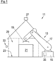
- Fig. 1 and 2 simplified illustrated loading / unloading 11 belongs to a production line and includes a robot 13, which in a basically known manner, a base 15, an articulated arm 17 and an end effector 19 has.
- a robot 13 instead of the robot 13, another type of automatic handling device, such as a gantry system, could be provided.
- a load carrier 21 in the form of a box-like container is placed on the floor 23.
- the objects 25 can be any individual parts or assemblies for automatic production.
- the end effector 19 of the robot 13 is designed to grip the objects 25 and can thus load a charge carrier 21 with objects 25 or unload objects 25 from a charge carrier 21.
- the working area of the robot 13 is monitored by a safety sensor 27 arranged above the robot 13. If necessary, the loading / unloading station 11 can also be provided with a plurality of safety sensors 27.
- the safety sensor 27 is preferably embodied as a 3D camera emitting depth information and spans a protective field 29 configured on the software side.
- An unillustrated control device of the loading / unloading station 11 communicates with the safety sensor 27 and ensures that, in the event of any intrusion of objects into the protective field 29, the robot 13 and optionally further movable system components are transferred to a safe state.
- Fig. 2 It can be seen that on both sides of the protective field 29 mechanical barriers 30 such. B. Fences are.
- an empty load carrier 21 is transported to the loading / unloading station 11 and placed on the floor 23. Subsequently, by means of the robot 13, objects 25 are removed one after the other from an object supply, not shown, and stored in the charge carrier 21. As soon as the charge carrier 21 is completely filled with or filled with objects, it is transported away again.
- the procedure is analogous, wherein initially a filled or populated load carrier 21 is transported to the loading / unloading station 11 and parked in the working area of the robot 13. The objects 25 are then removed one by one from the load carrier 21 by means of the robot 13 and fed to further processing in the production line.
- the transport of the charge carriers 21 to the loading / unloading station 11 and the removal of the load carriers 21 from the loading / unloading station 11 are preferably carried out by means of a forklift truck, a lift truck or a driverless transport system.
- the loading / unloading station 11 comprises a sensor arrangement 33, by means of which the position and the orientation of the charge carrier 21 within the working range of the robot 13 can be determined.
- the sensor assembly 33 in the illustrated embodiment comprises three distance sensors or 3D sensors 33a-c, the measuring fields are directed to respective side surfaces of the charge carrier 21. From a professional point of view, it goes without saying that a multiplicity of further sensor configurations is possible in order to detect the position of the charge carrier 21.
- the sensor arrangement 33 is connected to a control device 35 of the robot 13 and is configured to transmit the determined position of the parked load carrier 21 to the control device 35. If the charge carrier 21 is not parked exactly at the predetermined position, the corresponding incorrect positioning during operation of the robot 13 is taken into account. The robot 13 thus does not attack even with a mispositioned charge carrier 21. Collisions between the robot 13 and the charge carrier 21 are excluded.
- the sensor arrangement 33 could also be connected to the control device of a further robot, not shown, which is designed to handle charge carriers 21 and, if necessary, to correct the position of the parked charge carrier 21. In such an embodiment of the invention, not shown, the transmission of the determined position to the control device 35 of the robot 25 intended for handling the objects 25 would not necessarily be necessary. In principle, the sensor arrangement 33 could also be connected to a higher-level control device of the loading / unloading station 11.
- the safety sensor 27 could be designed to determine the position and orientation of the charge carrier 21 within the working range of the robot 13 and to transmit the determined position of the parked load carrier 21 to the control device 35. In such an embodiment, the safety sensor 27 would take over the task of the sensor arrangement and thus represent the sensor arrangement.
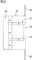
- Fig. 4 shows that the protective field 29 has an outer edge 37 (shown in phantom) and one along a recess 39 extending inner edge 41 (shown in phantom).
- the recess 39 serves to receive the charge carrier 21.
- the inner edge 41 is, as in Fig. 4 represented by arrows, adjusted on the basis of the determined position of the charge carrier 21, on the one hand to avoid a machine shutdown when entering the charge carrier 21 in the protective field 29 and on the other hand exclude a safety-critical gap between the carrier 21 and the inner edge 41 of the protective field 29.
- the outer edge 37 is adapted to maintain the standardized safety distances to the carrier 21.
- the protective field 29 can also be moved to adapt to the determined position of the charge carrier 21 as a whole.
- any incorrect positioning of the carrier 21 is automatically taken into account both in the control of the robot 13 and in the determination of the protective field 29, an accurate and prudent stopping of the carrier 21 during transport and careful removal of the carrier 21 during removal is not required. It is sufficient, in particular, that the charge carrier 21 is only parked approximately at the correct position. Accordingly, it is preferred that no mechanical stop for fixing the position of the charge carriers 21 is provided in the working area of the robot 13. In addition, it is not necessary to mark the predetermined position as such. Instead, a section of the work area can be defined as a tolerance range and marked accordingly, in which a parking of carriers 21 is permitted. For the operator of a forklift or lift truck, it is easy to place the load carriers 21 within the tolerance range and not to pay attention to a correct positioning. Likewise, it is advantageous that when transporting the charge carrier 21, it is not necessary to pay attention to a mechanical stop or the like. The invention thus enables a particularly efficient operation of the loading / unloading station 11 within the production line.
Landscapes
- Engineering & Computer Science (AREA)
- Robotics (AREA)
- Mechanical Engineering (AREA)
- Forklifts And Lifting Vehicles (AREA)
Priority Applications (1)
| Application Number | Priority Date | Filing Date | Title |
|---|---|---|---|
| EP15171273.4A EP3103596A1 (fr) | 2015-06-09 | 2015-06-09 | Procédé de charge de porteurs de charges et station de charge/décharge |
Applications Claiming Priority (1)
| Application Number | Priority Date | Filing Date | Title |
|---|---|---|---|
| EP15171273.4A EP3103596A1 (fr) | 2015-06-09 | 2015-06-09 | Procédé de charge de porteurs de charges et station de charge/décharge |
Publications (1)
| Publication Number | Publication Date |
|---|---|
| EP3103596A1 true EP3103596A1 (fr) | 2016-12-14 |
Family
ID=53541495
Family Applications (1)
| Application Number | Title | Priority Date | Filing Date |
|---|---|---|---|
| EP15171273.4A Ceased EP3103596A1 (fr) | 2015-06-09 | 2015-06-09 | Procédé de charge de porteurs de charges et station de charge/décharge |
Country Status (1)
| Country | Link |
|---|---|
| EP (1) | EP3103596A1 (fr) |
Cited By (1)
| Publication number | Priority date | Publication date | Assignee | Title |
|---|---|---|---|---|
| US20220016779A1 (en) * | 2020-07-15 | 2022-01-20 | The Board Of Trustees Of The University Of Illinois | Autonomous Robot Packaging of Arbitrary Objects |
Citations (5)
| Publication number | Priority date | Publication date | Assignee | Title |
|---|---|---|---|---|
| DE10324627A1 (de) * | 2003-05-28 | 2005-01-05 | Daimlerchrysler Ag | Arbeitsraumüberwachung für automatisiert arbeitende Maschinen |
| DE102007026956A1 (de) * | 2007-06-12 | 2008-12-18 | Kuka Innotec Gmbh | Verfahren und System zum Roboter geführten Depalettieren von Reifen |
| EP2048557A1 (fr) * | 2007-10-11 | 2009-04-15 | Sick Ag | Capteur optoélectronique et dispositif mobile ainsi que son procédé de configuration |
| EP2380709A2 (fr) * | 2010-04-22 | 2011-10-26 | Sick AG | Dispositif de sécurité 3D et procédé de sécurisation et de commande d'au moins une machine |
| EP2745999A1 (fr) * | 2011-08-19 | 2014-06-25 | Kabushiki Kaisha Yaskawa Denki | Système de robot, dispositif de commande de robot, main de robot et procédé de commande de robot |
-
2015
- 2015-06-09 EP EP15171273.4A patent/EP3103596A1/fr not_active Ceased
Patent Citations (5)
| Publication number | Priority date | Publication date | Assignee | Title |
|---|---|---|---|---|
| DE10324627A1 (de) * | 2003-05-28 | 2005-01-05 | Daimlerchrysler Ag | Arbeitsraumüberwachung für automatisiert arbeitende Maschinen |
| DE102007026956A1 (de) * | 2007-06-12 | 2008-12-18 | Kuka Innotec Gmbh | Verfahren und System zum Roboter geführten Depalettieren von Reifen |
| EP2048557A1 (fr) * | 2007-10-11 | 2009-04-15 | Sick Ag | Capteur optoélectronique et dispositif mobile ainsi que son procédé de configuration |
| EP2380709A2 (fr) * | 2010-04-22 | 2011-10-26 | Sick AG | Dispositif de sécurité 3D et procédé de sécurisation et de commande d'au moins une machine |
| EP2745999A1 (fr) * | 2011-08-19 | 2014-06-25 | Kabushiki Kaisha Yaskawa Denki | Système de robot, dispositif de commande de robot, main de robot et procédé de commande de robot |
Cited By (2)
| Publication number | Priority date | Publication date | Assignee | Title |
|---|---|---|---|---|
| US20220016779A1 (en) * | 2020-07-15 | 2022-01-20 | The Board Of Trustees Of The University Of Illinois | Autonomous Robot Packaging of Arbitrary Objects |
| US12390931B2 (en) * | 2020-07-15 | 2025-08-19 | Duke University | Autonomous robot packaging of arbitrary objects |
Similar Documents
| Publication | Publication Date | Title |
|---|---|---|
| DE102018124712B4 (de) | Arbeitssystem, Verfahren zum Durchführen von Arbeit an einem Objekt und Roboter | |
| EP3571020B1 (fr) | Procédé et dispositif de préparation de commandes de marchandises | |
| EP3601118B1 (fr) | Système de production équipé d'un ftf servant à automatiser la distribution de contenants sur des rayonnages de prélèvement | |
| EP3289852B2 (fr) | Véhicule de transport | |
| EP3638616B1 (fr) | Machine de traitement des recipients avec robot mobil pour changer des composants | |
| EP2745982B1 (fr) | Système de production | |
| EP3020614B1 (fr) | Systeme de convoyage d'objets et son procede de commande | |
| DE102007026956A1 (de) | Verfahren und System zum Roboter geführten Depalettieren von Reifen | |
| EP3953743B1 (fr) | Dispositif de fabrication et moyen de transport | |
| EP2444320A2 (fr) | Système de charge de cargaison et procédé de détermination du mouvement d'une pièce de cargaison sur un toit de cargaison | |
| DE102018106458A1 (de) | Produktionssystem | |
| DE102020100803A1 (de) | Folgeroboter und Roboterarbeitssystem | |
| DE102019001125B4 (de) | Fördereinrichtung für Ladungsträger mit integrierter Kollisionsdetektion | |
| EP3812340A1 (fr) | Charriot de manutention, équipé pour un fonctionnement sans conducteur et autonome | |
| DE202017107882U1 (de) | Flaschenreinigungsmaschine zum Reinigen von Flaschen | |
| DE102011109532A1 (de) | Anlage und Verfahren zum Betreiben einer Anlage | |
| EP4439218A1 (fr) | Véhicule de transport sans conducteur | |
| EP4269321B1 (fr) | Dispositif de transport pour porteurs de charge | |
| EP3103596A1 (fr) | Procédé de charge de porteurs de charges et station de charge/décharge | |
| EP3976447B1 (fr) | Système comprenant un chariot tracteur et au moins un poste de transfert stationnaire | |
| EP2385013A1 (fr) | Chariot de manutention doté d'un dispositif destiné à la surveillance de la position d'un produit de transport chargé et procédé destiné à la surveillance de la position d'un produit de transport chargé d'un chariot de manutention | |
| EP2452900A2 (fr) | Commissionnement de palettes | |
| DE102014201616B4 (de) | Modulare, universelle Abstapelanlage von Groß-Pressteilen | |
| EP4534457B1 (fr) | Système de manipulation pour l'assemblage automatisé de pneus de véhicule à un ensemble palier | |
| DE102020212661A1 (de) | Vorrichtung und Verfahren zur exakten und reproduzierbaren Positionierung von Transporteinrichtungen |
Legal Events
| Date | Code | Title | Description |
|---|---|---|---|
| PUAI | Public reference made under article 153(3) epc to a published international application that has entered the european phase |
Free format text: ORIGINAL CODE: 0009012 |
|
| STAA | Information on the status of an ep patent application or granted ep patent |
Free format text: STATUS: EXAMINATION IS IN PROGRESS |
|
| 17P | Request for examination filed |
Effective date: 20160330 |
|
| AK | Designated contracting states |
Kind code of ref document: A1 Designated state(s): AL AT BE BG CH CY CZ DE DK EE ES FI FR GB GR HR HU IE IS IT LI LT LU LV MC MK MT NL NO PL PT RO RS SE SI SK SM TR |
|
| AX | Request for extension of the european patent |
Extension state: BA ME |
|
| STAA | Information on the status of an ep patent application or granted ep patent |
Free format text: STATUS: THE APPLICATION HAS BEEN REFUSED |
|
| 18R | Application refused |
Effective date: 20171028 |