EP3103603A1 - Verschlusskappenschneidemaschine - Google Patents
Verschlusskappenschneidemaschine Download PDFInfo
- Publication number
- EP3103603A1 EP3103603A1 EP16170732.8A EP16170732A EP3103603A1 EP 3103603 A1 EP3103603 A1 EP 3103603A1 EP 16170732 A EP16170732 A EP 16170732A EP 3103603 A1 EP3103603 A1 EP 3103603A1
- Authority
- EP
- European Patent Office
- Prior art keywords
- cap
- rotation
- axis
- housing
- cutting
- Prior art date
- Legal status (The legal status is an assumption and is not a legal conclusion. Google has not performed a legal analysis and makes no representation as to the accuracy of the status listed.)
- Granted
Links
Images

Classifications
-
- B—PERFORMING OPERATIONS; TRANSPORTING
- B26—HAND CUTTING TOOLS; CUTTING; SEVERING
- B26F—PERFORATING; PUNCHING; CUTTING-OUT; STAMPING-OUT; SEVERING BY MEANS OTHER THAN CUTTING
- B26F1/00—Perforating; Punching; Cutting-out; Stamping-out; Apparatus therefor
- B26F1/18—Perforating by slitting, i.e. forming cuts closed at their ends without removal of material
-
- B—PERFORMING OPERATIONS; TRANSPORTING
- B26—HAND CUTTING TOOLS; CUTTING; SEVERING
- B26D—CUTTING; DETAILS COMMON TO MACHINES FOR PERFORATING, PUNCHING, CUTTING-OUT, STAMPING-OUT OR SEVERING
- B26D1/00—Cutting through work characterised by the nature or movement of the cutting member or particular materials not otherwise provided for; Apparatus or machines therefor; Cutting members therefor
- B26D1/01—Cutting through work characterised by the nature or movement of the cutting member or particular materials not otherwise provided for; Apparatus or machines therefor; Cutting members therefor involving a cutting member which does not travel with the work
- B26D1/02—Cutting through work characterised by the nature or movement of the cutting member or particular materials not otherwise provided for; Apparatus or machines therefor; Cutting members therefor involving a cutting member which does not travel with the work having a stationary cutting member
-
- B—PERFORMING OPERATIONS; TRANSPORTING
- B26—HAND CUTTING TOOLS; CUTTING; SEVERING
- B26D—CUTTING; DETAILS COMMON TO MACHINES FOR PERFORATING, PUNCHING, CUTTING-OUT, STAMPING-OUT OR SEVERING
- B26D3/00—Cutting work characterised by the nature of the cut made; Apparatus therefor
- B26D3/08—Making a superficial cut in the surface of the work without removal of material, e.g. scoring, incising
-
- B—PERFORMING OPERATIONS; TRANSPORTING
- B26—HAND CUTTING TOOLS; CUTTING; SEVERING
- B26D—CUTTING; DETAILS COMMON TO MACHINES FOR PERFORATING, PUNCHING, CUTTING-OUT, STAMPING-OUT OR SEVERING
- B26D7/00—Details of apparatus for cutting, cutting-out, stamping-out, punching, perforating, or severing by means other than cutting
- B26D7/01—Means for holding or positioning work
-
- B—PERFORMING OPERATIONS; TRANSPORTING
- B26—HAND CUTTING TOOLS; CUTTING; SEVERING
- B26D—CUTTING; DETAILS COMMON TO MACHINES FOR PERFORATING, PUNCHING, CUTTING-OUT, STAMPING-OUT OR SEVERING
- B26D7/00—Details of apparatus for cutting, cutting-out, stamping-out, punching, perforating, or severing by means other than cutting
- B26D7/06—Arrangements for feeding or delivering work of other than sheet, web, or filamentary form
-
- B—PERFORMING OPERATIONS; TRANSPORTING
- B26—HAND CUTTING TOOLS; CUTTING; SEVERING
- B26F—PERFORATING; PUNCHING; CUTTING-OUT; STAMPING-OUT; SEVERING BY MEANS OTHER THAN CUTTING
- B26F2210/00—Perforating, punching, cutting-out, stamping-out, severing by means other than cutting of specific products
- B26F2210/04—Making plastic pilferproof screw caps by cutting a tamper ring
Definitions
- the invention has for an object a cap cutting machine for cutting caps.
- the machine according to the present invention is arranged to perform cutting on the side surface of the cap so that a warranty ring is formed.
- the cutting of the warranty ring occurs via machines that include one or more spindles whereon the caps are fitted.
- the caps are brought in contact with a series of concentric discs, at least one of which is a motor that sets the caps in rotation by friction on an outer surface.
- a further disc is the blade that performs the cutting.
- the machines currently available require that the caps are of rather regular shape, with a rather extended side surface and provided with a knurling which serves to promote rotary dragging of the caps by the motor disc.
- cap cutting machines of the prior art are rather complex and less flexible. In the event of a format change of the cap, there is in fact a need for the cutting machine to be tailor-made accordingly, and this is a long and laborious operation.
- An advantage of the machine is to be able to operate even on irregularly shaped caps exhibiting complex and stepped side surfaces.
- a further advantage of the machine is to allow rapid format changes.
- Another advantage of the machine according to the invention is to be fast and reliable.
- the machine according to the present invention is of the rotary type.
- the machine comprises a rotary turret disposed about a main axis of rotation (Y) to which the caps (C) to be processed are fed.
- the caps (C) are processed aboard the turret during rotation of the same up to an ejection station, from which the caps proceed to further manufacturing.
- the caps (C) are preferably fed via a star device which is known to those skilled in the art and thus not shown in detail herein.
- the machine comprises a housing assembly (2) which is movable along a pre-determined path (P).
- the path (P) is a circular path, whereas in the case of a linear structure the path (P) might be rectilinear.
- the rotary turret or rotating structure may be provided with a plurality of housing assemblies (2) being distributed circularly at a constant angular pitch.
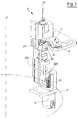
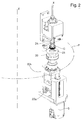
- figures 1 and 2 illustrate a single housing assembly (2) with indication of the path (P) and the main axis of rotation (Y).
- the man skilled in the art is perfectly capable of arranging a turret-like rotating structure provided with a plurality of housing assemblies (2).
- the housing assembly (2) is provided with a rotary housing (20) which is so structured as to accommodate a cap (C) and to make the cap (C) rotate about a first axis of rotation (X).
- the rotary housing (20) substantially exhibits an annular shape which delimits a cylindrical compartment (20a) that is concentric with the first axis of rotation (X) and open at the ends thereof.
- the axis of rotation (X) is oriented vertically and a cap (C) can be inserted into the housing (20) through the upper end of the compartment (20a).
- the cutting means (3) is so conformed as to perform a cutting on a side surface of the cap (C).
- the cutting means (3) is arranged along an active tract of the path (P), thereby exerting its action over a certain tract of the path (P) during the motion of the housing assembly (2) along the path (P) same.
- the cutting means (3) comprises a circular cutting sector (31) concentric with the main axis of rotation (Y).
- the cutting sector (31) is stationary, i.e. arranged fixed along the active tract of the path (P).
- the cutting means may assume a different conformation and/or be movable along the path (P).
- the motor means (5) is so structured as to cause rotation of the rotary housing (20) about the first axis of rotation (X) so that, at least along the active tract of the path (P), the housing (20) moves according to a pure rolling motion with respect to the cutting means (3).
- a side surface of the cap (C) can come into contact with the cutting means (3) by rolling without sliding with respect to the latter.
- the action of the motor means (5) causes the rotary housing (20) to move according to a pure rolling motion with respect the circular cutting sector (31), which implies that also a cap (C) contained in said rotary housing (20) exhibits a pure rolling motion relative to the circular cutting sector (31).
- the rotary housing (20) is capable of setting in rotation complex-shaped caps (C) exhibiting side stepped surfaces (as the cap shown in the figure) and/or knurls-free side surfaces.
- the cutting which is obtained as a result of a pure rolling motion is particularly accurate and clean and further allows to simplify the structure of the cutting means (3), which cutting means (3) may even take on the above-described circular cutting sector (31) configuration.
- the motor means (5) comprises for example a servo motor that is configured for rotating the rotary housing (20) about the first axis of rotation (X).
- the servo motor is governed by a control unit, not shown, which is capable of implementing rotation of the motor in order to obtain the effects described above.
- the solution of adopting independent motor means (5) for each rotary housing (20) simplifies the structure of the machine from the mechanical viewpoint in that, owing to this configuration, complex mechanical transmissions are not required, moreover the presence of independent motor means (5) makes it possible to control rotation of each rotary housing (20) in the desired manner.
- the rotary housing (20) is further slidingly movable along the first axis of rotation (X) between a lower position, relative to which a cap (C) can be aligned to the rotary housing (20), and an upper position, at which the rotary housing (20) is arranged around the cap (C). In the upper position, the rotary housing (20) leaves uncovered the zone of the cap (C) intended to come into contact with the cutting means (3).
- the possibility of translating the rotary housing (20) between the lower position and the upper position allows to feed the caps (C) by way of a rotary star feeder, not shown, which is known to be easy-to use, reliable and fast.
- the housing assembly (2) comprises a lower portion (22) with which the rotary housing is associated (20).
- the lower portion (22) is movable in rotation about the first axis of rotation (X).
- the lower portion (22) is further associated with a support (22b) which is slidingly movable along the first axis of rotation (X) for translating the housing (20) between the lower and upper positions.
- the motor means (5) transmits the rotary motion to the lower portion (22) via a toothed shaft (51) that meshes with a toothed wheel (22a) that is rotatingly integral with the lower portion (22).
- the sliding motion along the first axis of rotation (X) is instead transmitted to the support (22b) via a fixed cam profile (CP), which interacts with the support (22b) itself during the motion along the path (P).
- a cap (C) can be positioned above the rotary housing (2), which cap (C) is substantially aligned and concentric with respect to the first axis of rotation (X).
- the cap (C) is placed at least partially within the rotary housing itself (20). A portion of the cap (C), whereon the cutting is to be effected, remains protruding from the rotary housing (20).
- the housing assembly (2) comprises an abutment (23), which is disposed internally of the rotary housing (20).
- the abutment (23) substantially performs the function of bottom of the rotary housing (20) and of resting base for a cap (C).
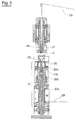
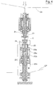
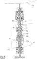
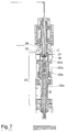
- the rotary housing (20) and the abutment (23) are movable one to another along the first axis of rotation (X), between a first position, visible in Figures 3 and 4 , in which the abutment (23) is located at an upper edge of the housing (20), and a second position, visible in figure 5 , in which the abutment (23) is located at a lower edge of the housing (20).
- the rotary housing (20) by means of the support (22b), is slidable along the first axis of rotation (X) with respect to the abutment (23).
- the first and second position are then defined by the position assumed by the rotary housing (20).
- the abutment (23) is integral with a pin (23a), in a single piece or in two portions, which is coaxial with the first axis of rotation (X) and which is passing through the lower portion (22) of the housing assembly ( 2), wherefrom it protrudes downwards.
- the rotary housing (20) is removable from the housing assembly (2), and in particular is removable with respect to the lower portion (22). In this way the rotating housing (20) may be replaced according to the characteristics of the cap to be treated.
- the housing assembly (2) further comprises a locking pin (21) arranged superiorly to the rotary housing (20) and substantially concentric with the first axis of rotation (X).
- the locking pin (21) is so structured as to be disposed at least partially internally of the rotary housing (20).
- the locking pin (21) is movable between a first upper position in the embodiment shown, in which the locking pin (21) is located at a greater distance from the rotary housing (20), and a second lower position, wherein such locking pin (21) is located at a smaller distance from the rotary housing (20) and can be arranged at least partially internally of the latter, pressing the cap (C) on the bottom of the rotary housing (20) itself.
- the displacement of the locking pin (21) is implemented by way of a fixed cam profile (CS), illustrated only schematically, which interacts with one end (21 a) of the pin (21) itself.
- the displacement of the locking pin (21) is synchronized with the displacement of the rotary housing (20) in the following way.
- the locking pin (21) which is in its first position, moves toward the its second position ( figure 4 ), in which it is arranged inside the cap (C) and presses the latter against the abutment (23).
- the housing (20) moves from its lower position to the upper position ( Figure 5 ), surrounding the cap (C).
- the housing assembly (2) is further provided with a contrast bush (24), which is structured for pushing the cap (C) towards the cutting means (3).
- the bush (24) is arranged concentrically to the first axis of rotation (X).
- the bush (24) is concentric with the locking pin (21).
- the bush (24) is movable along a direction perpendicular to the axis of rotation (X) between an active position, at which it is located at a smaller distance from the cutting means (3) along the active tract of the path (P), and an inactive position, at which it is located at a greater distance from the cutting means (3) along the active tract of the path (P).
- the bush (24) moves away radially from the main axis of rotation (Y).
- the bush (24) comes in contact with a side area of the cap (C) and is able to press a cap (C) in contact with the cutting means (3) during rotation of the cap itself by virtue of the rotary housing (20).
- the bush (24) In the inactive position the bush (24) can be inserted into or extracted from the cap (C).
- the rotary bush (24) is free to rotate about the first axis of rotation (X), in order to not hinder rotation of the cap (C).
- Shifting means (4) are capable of moving the contrast bush (24) from the inactive position to the active position along the active tract of the path (P).
- Such shifting means (4) comprises an annular element (41) arranged around the bush (24).
- the annular element (41) is in turn movable in the direction perpendicular to the first axis of rotation (X) for translating the bush (24) between the active and inactive positions.
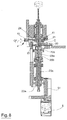
- the shifting of the annular element (41) is obtained by means of a fixed cam (CF), depicted schematically in Figure 8 , which comes into contact with the annular element at least along the active tract of the path (P), i.e. along the tract in which the cutting means (3) comes into contact with the cap (C).
- CF fixed cam
- the displacement of the abutment (23) in the cutting position is obtained via a second fixed cam profile (CP2) that is substantially parallel to the first cam profile (CP) but is out of phase by a pitch which is sufficient to enable initially the displacement of the rotary housing (20) in the upper position thereof, and thereafter the simultaneous displacement of the rotary housing (20) and of the abutment (23) towards the cutting position.
- the second cam profile (CP2) interacts with the end of the pin (23a) to which the abutment (23) is associated.
- the locking pin (21) yields to the pressure exerted by the abutment (23), whereby the locking pin (21) returns upwards thanks to the presence of an elastic element, for example a pneumatic spring.
- the bush (24) moves towards its active position ( figure 8 ), wherein it is arranged in contact with a side part of the cap (C) and pushes the cap (C) towards the cutting means (3) and in contact with the same, along the active tract of the path (P).
- the rotary housing (20) has been set in rotation by the motor means (5) in order to perform cutting through the pure rolling motion of the cap (C) on the cutting means (3).
- each housing assembly (2) performs the movements described above in reverse order, thus returning into the initial configuration of Figure 3 to receive a new cap (C), all this during the displacement along the path (P), i.e. during rotation of the rotating turret to which the housing assemblies (2) are associated.
- a phasing of the angular position of the cap (C) with respect to the first axis of rotation (X) may be further performed. Such phasing may be obtained for example via optical means capable of detecting the angular position of the cap. The detected angular position is transmitted to the control unit which drives the motor means (5) for rotating the rotary housing (20) to obtain the desired angular position.
- the machine according to the present invention achieves important advantages. First of all, it allows to perform circular cutting on complex-shaped and/or lateral knurling-free caps. Furthermore, the cutting performed through the pure rolling motion of the cap on the cutting means, is very accurate which result in cutting means easy to use and obtainable at low cost.
Landscapes
- Life Sciences & Earth Sciences (AREA)
- Forests & Forestry (AREA)
- Engineering & Computer Science (AREA)
- Mechanical Engineering (AREA)
- Casting Or Compression Moulding Of Plastics Or The Like (AREA)
- Devices For Opening Bottles Or Cans (AREA)
- Closing Of Containers (AREA)
- Sealing Of Jars (AREA)
Applications Claiming Priority (1)
| Application Number | Priority Date | Filing Date | Title |
|---|---|---|---|
| ITUB20151303 | 2015-06-08 |
Publications (2)
| Publication Number | Publication Date |
|---|---|
| EP3103603A1 true EP3103603A1 (de) | 2016-12-14 |
| EP3103603B1 EP3103603B1 (de) | 2017-10-18 |
Family
ID=54325604
Family Applications (1)
| Application Number | Title | Priority Date | Filing Date |
|---|---|---|---|
| EP16170732.8A Active EP3103603B1 (de) | 2015-06-08 | 2016-05-20 | Verschlusskappenschneidemaschine |
Country Status (4)
| Country | Link |
|---|---|
| US (1) | US10052782B2 (de) |
| EP (1) | EP3103603B1 (de) |
| CA (1) | CA2931643C (de) |
| ES (1) | ES2651340T3 (de) |
Cited By (6)
| Publication number | Priority date | Publication date | Assignee | Title |
|---|---|---|---|---|
| IT201800010118A1 (it) * | 2018-11-07 | 2020-05-07 | Sacmi | Apparato e metodo di taglio |
| EP3943260A1 (de) * | 2020-07-22 | 2022-01-26 | Contexo GmbH | Vorrichtung und verfahren zum herstellen einer verschlusskappe |
| IT202100003656A1 (it) | 2021-02-17 | 2022-08-17 | Sacmi | Apparato e metodo di taglio per capsule |
| WO2022175824A1 (en) * | 2021-02-17 | 2022-08-25 | Sacmi Cooperativa Meccanici Imola Societa' Cooperativa | Cutting apparatus and method for capsules |
| IT202200002165A1 (it) | 2022-02-07 | 2023-08-07 | Sacmi | Apparato e metodo di taglio per capsule |
| TWI923691B (zh) | 2021-02-17 | 2026-05-01 | 義大利商沙克米機械商業合作艾莫勒精簡公司 | 用於容器帽的切割裝置和方法 |
Families Citing this family (8)
| Publication number | Priority date | Publication date | Assignee | Title |
|---|---|---|---|---|
| TWI589498B (zh) * | 2015-04-02 | 2017-07-01 | 邁可約瑟夫 麥奎爾 | 容器用之蓋子 |
| EP3103603B1 (de) * | 2015-06-08 | 2017-10-18 | Bortolin Kemo S.P.A. | Verschlusskappenschneidemaschine |
| IT201900014004A1 (it) * | 2019-08-05 | 2021-02-05 | Sacmi | Apparato per Tagliare Capsule |
| EP3800020A1 (de) * | 2019-10-03 | 2021-04-07 | PackSys Global AG | Vorrichtung und verfahren zum herstellen eines sicherungsrings an einer verschlusskappe für einen behälter |
| EP3831557A1 (de) | 2019-12-05 | 2021-06-09 | PackSys Global AG | Vorrichtung und verfahren zum herstellen einer schnittgeometrie in einer verschlusskappe für einen behälter |
| IT202000016570A1 (it) * | 2020-07-08 | 2022-01-08 | Sacmi | Apparato di taglio |
| IT202100017933A1 (it) * | 2021-07-07 | 2023-01-07 | Sacmi | Coltello per incidere capsule |
| IT202200003392A1 (it) | 2022-02-23 | 2023-08-23 | Sacmi | Apparato e metodo di taglio capsule |
Citations (3)
| Publication number | Priority date | Publication date | Assignee | Title |
|---|---|---|---|---|
| CA1161611A (en) * | 1982-03-29 | 1984-02-07 | Hamelin Inc. | Process and apparatus for production of bottle caps with tear strips |
| US5651299A (en) * | 1994-03-08 | 1997-07-29 | H-C Industries, Inc. | Method for scoring a tamper-indicating plastic closure |
| EP1243520A1 (de) * | 2001-03-19 | 2002-09-25 | Oberburg Engineering Ag | Verfahren und Vorrichtung zum Bearbeiten einer Verschlusskapsel |
Family Cites Families (7)
| Publication number | Priority date | Publication date | Assignee | Title |
|---|---|---|---|---|
| US5660289A (en) * | 1991-06-29 | 1997-08-26 | Alcoa Deutschland Gmbh | Plastic cap for containers |
| US5557999A (en) * | 1994-01-14 | 1996-09-24 | H-C Industries, Inc. | Method for manufacturing a tamper-indicating plastic closure |
| US20070089587A1 (en) * | 2005-10-26 | 2007-04-26 | Chi-Ti Liao | Mechanism making braking lines for container caps |
| IT1396233B1 (it) | 2009-11-10 | 2012-11-16 | Sacmi | Apparato e metodo di taglio |
| JP5809835B2 (ja) * | 2011-04-14 | 2015-11-11 | ニチアス株式会社 | 切断装置 |
| EP2969415B1 (de) * | 2014-06-02 | 2017-04-05 | GEFU-Küchenboss GmbH & Co. KG | Vorrichtung zum spiralförmigen schneiden von schnittfestem schneidgut |
| EP3103603B1 (de) * | 2015-06-08 | 2017-10-18 | Bortolin Kemo S.P.A. | Verschlusskappenschneidemaschine |
-
2016
- 2016-05-20 EP EP16170732.8A patent/EP3103603B1/de active Active
- 2016-05-20 ES ES16170732.8T patent/ES2651340T3/es active Active
- 2016-05-25 CA CA2931643A patent/CA2931643C/en active Active
- 2016-05-26 US US15/165,508 patent/US10052782B2/en active Active
Patent Citations (3)
| Publication number | Priority date | Publication date | Assignee | Title |
|---|---|---|---|---|
| CA1161611A (en) * | 1982-03-29 | 1984-02-07 | Hamelin Inc. | Process and apparatus for production of bottle caps with tear strips |
| US5651299A (en) * | 1994-03-08 | 1997-07-29 | H-C Industries, Inc. | Method for scoring a tamper-indicating plastic closure |
| EP1243520A1 (de) * | 2001-03-19 | 2002-09-25 | Oberburg Engineering Ag | Verfahren und Vorrichtung zum Bearbeiten einer Verschlusskapsel |
Cited By (11)
| Publication number | Priority date | Publication date | Assignee | Title |
|---|---|---|---|---|
| IT201800010118A1 (it) * | 2018-11-07 | 2020-05-07 | Sacmi | Apparato e metodo di taglio |
| WO2020095145A1 (en) * | 2018-11-07 | 2020-05-14 | Sacmi Cooperativa Meccanici Imola Societa' Cooperativa | Cutting apparatus and method |
| CN112888539A (zh) * | 2018-11-07 | 2021-06-01 | 沙克米机械商业合作艾莫勒精简公司 | 切割设备和方法 |
| US11577421B2 (en) | 2018-11-07 | 2023-02-14 | Sacmi Cooperativa Meccanici Imola Societa' Cooperativa | Cutting apparatus and method |
| EP4570463A3 (de) * | 2018-11-07 | 2025-09-10 | Sacmi Cooperativa Meccanici Imola Societa' Cooperativa | Schneidvorrichtung und -verfahren |
| EP3943260A1 (de) * | 2020-07-22 | 2022-01-26 | Contexo GmbH | Vorrichtung und verfahren zum herstellen einer verschlusskappe |
| IT202100003656A1 (it) | 2021-02-17 | 2022-08-17 | Sacmi | Apparato e metodo di taglio per capsule |
| WO2022175824A1 (en) * | 2021-02-17 | 2022-08-25 | Sacmi Cooperativa Meccanici Imola Societa' Cooperativa | Cutting apparatus and method for capsules |
| JP2024512239A (ja) * | 2021-02-17 | 2024-03-19 | サクミ コオペラティヴァ メッカニチ イモラ ソシエタ コオペラティヴァ | カプセル用の切断装置及び方法 |
| TWI923691B (zh) | 2021-02-17 | 2026-05-01 | 義大利商沙克米機械商業合作艾莫勒精簡公司 | 用於容器帽的切割裝置和方法 |
| IT202200002165A1 (it) | 2022-02-07 | 2023-08-07 | Sacmi | Apparato e metodo di taglio per capsule |
Also Published As
| Publication number | Publication date |
|---|---|
| CA2931643A1 (en) | 2016-12-08 |
| EP3103603B1 (de) | 2017-10-18 |
| CA2931643C (en) | 2018-11-20 |
| ES2651340T3 (es) | 2018-01-25 |
| US10052782B2 (en) | 2018-08-21 |
| US20160354946A1 (en) | 2016-12-08 |
Similar Documents
| Publication | Publication Date | Title |
|---|---|---|
| US10052782B2 (en) | Cap cutting machine | |
| US8919223B2 (en) | Variable cam, particularly for machines for applying closures | |
| US10589889B2 (en) | Labelling machine | |
| RU2205746C2 (ru) | Устройство для образования борозды в цилиндрической стенке пластикового колпачка, в частности пластиковой крышки для закрывания контейнера, и машина для его использования | |
| EP4164877B1 (de) | Vorrichtung und verfahren zum biegen von rohrförmigen produkten | |
| CN100354081C (zh) | 用于制造塑性盖中杯和安全环之间断裂切口的设备 | |
| EP1566359A1 (de) | Verschliesskopf für Schraubkappen | |
| US3538678A (en) | Bottle stoppering machine | |
| WO2004039553A1 (en) | Device for removing doses of plastic material from an extruder | |
| WO2015177055A1 (en) | Carousel for processing containers | |
| EP1145966A1 (de) | Vorrichtung zum Aufnehmen und Ausrichten von Behältern | |
| EP2990344B1 (de) | Behälterbehandlungsmaschine und -Verfahren | |
| EP3351482B1 (de) | Teller für etikettiermaschine uned etikettierkarussell umfassend mehrere teller | |
| EP2990343B1 (de) | Behälterbehandlungsmaschine und -Verfahren | |
| EP3022120B1 (de) | Etikettierungsmaschine mit karussell | |
| CA1161611A (en) | Process and apparatus for production of bottle caps with tear strips | |
| EP4686675A1 (de) | Trägerplattenvorrichtung zum tragen eines behälters und betriebsmaschine mit dieser trägerplattenvorrichtung | |
| US2750913A (en) | Can and cover feeding mechanism | |
| US2673018A (en) | Machine for securing caps to glass jars | |
| EP3095719A1 (de) | Karussell zur verarbeitung von behältern | |
| US2324506A (en) | Spot machine | |
| US3310449A (en) | Labeling machine with yieldable drive means for picker and emergency stop | |
| EP2673199B1 (de) | Einheit zum anbringen eines etiketts auf einem entsprechenden artikel |
Legal Events
| Date | Code | Title | Description |
|---|---|---|---|
| PUAI | Public reference made under article 153(3) epc to a published international application that has entered the european phase |
Free format text: ORIGINAL CODE: 0009012 |
|
| AK | Designated contracting states |
Kind code of ref document: A1 Designated state(s): AL AT BE BG CH CY CZ DE DK EE ES FI FR GB GR HR HU IE IS IT LI LT LU LV MC MK MT NL NO PL PT RO RS SE SI SK SM TR |
|
| AX | Request for extension of the european patent |
Extension state: BA ME |
|
| RBV | Designated contracting states (corrected) |
Designated state(s): AL AT BE BG CH CY CZ DE DK EE ES FI FR GB GR HR HU IE IS IT LI LT LU LV MC MK MT NL NO PL PT RO RS SE SI SK SM TR |
|
| 17P | Request for examination filed |
Effective date: 20170206 |
|
| GRAP | Despatch of communication of intention to grant a patent |
Free format text: ORIGINAL CODE: EPIDOSNIGR1 |
|
| RIC1 | Information provided on ipc code assigned before grant |
Ipc: B26D 7/06 20060101ALI20170614BHEP Ipc: B26D 3/08 20060101AFI20170614BHEP Ipc: B26D 1/02 20060101ALI20170614BHEP Ipc: B26F 1/18 20060101ALI20170614BHEP Ipc: B65D 41/32 20060101ALI20170614BHEP Ipc: B26D 7/01 20060101ALI20170614BHEP |
|
| INTG | Intention to grant announced |
Effective date: 20170719 |
|
| GRAS | Grant fee paid |
Free format text: ORIGINAL CODE: EPIDOSNIGR3 |
|
| GRAA | (expected) grant |
Free format text: ORIGINAL CODE: 0009210 |
|
| AK | Designated contracting states |
Kind code of ref document: B1 Designated state(s): AL AT BE BG CH CY CZ DE DK EE ES FI FR GB GR HR HU IE IS IT LI LT LU LV MC MK MT NL NO PL PT RO RS SE SI SK SM TR |
|
| REG | Reference to a national code |
Ref country code: GB Ref legal event code: FG4D |
|
| REG | Reference to a national code |
Ref country code: CH Ref legal event code: EP |
|
| REG | Reference to a national code |
Ref country code: CH Ref legal event code: NV Representative=s name: BUGNION S.A., CH Ref country code: AT Ref legal event code: REF Ref document number: 937538 Country of ref document: AT Kind code of ref document: T Effective date: 20171115 Ref country code: IE Ref legal event code: FG4D |
|
| REG | Reference to a national code |
Ref country code: DE Ref legal event code: R096 Ref document number: 602016000591 Country of ref document: DE |
|
| REG | Reference to a national code |
Ref country code: ES Ref legal event code: FG2A Ref document number: 2651340 Country of ref document: ES Kind code of ref document: T3 Effective date: 20180125 |
|
| REG | Reference to a national code |
Ref country code: NL Ref legal event code: MP Effective date: 20171018 |
|
| REG | Reference to a national code |
Ref country code: LT Ref legal event code: MG4D |
|
| REG | Reference to a national code |
Ref country code: AT Ref legal event code: MK05 Ref document number: 937538 Country of ref document: AT Kind code of ref document: T Effective date: 20171018 |
|
| PG25 | Lapsed in a contracting state [announced via postgrant information from national office to epo] |
Ref country code: NL Free format text: LAPSE BECAUSE OF FAILURE TO SUBMIT A TRANSLATION OF THE DESCRIPTION OR TO PAY THE FEE WITHIN THE PRESCRIBED TIME-LIMIT Effective date: 20171018 |
|
| PG25 | Lapsed in a contracting state [announced via postgrant information from national office to epo] |
Ref country code: FI Free format text: LAPSE BECAUSE OF FAILURE TO SUBMIT A TRANSLATION OF THE DESCRIPTION OR TO PAY THE FEE WITHIN THE PRESCRIBED TIME-LIMIT Effective date: 20171018 Ref country code: LT Free format text: LAPSE BECAUSE OF FAILURE TO SUBMIT A TRANSLATION OF THE DESCRIPTION OR TO PAY THE FEE WITHIN THE PRESCRIBED TIME-LIMIT Effective date: 20171018 Ref country code: NO Free format text: LAPSE BECAUSE OF FAILURE TO SUBMIT A TRANSLATION OF THE DESCRIPTION OR TO PAY THE FEE WITHIN THE PRESCRIBED TIME-LIMIT Effective date: 20180118 Ref country code: SE Free format text: LAPSE BECAUSE OF FAILURE TO SUBMIT A TRANSLATION OF THE DESCRIPTION OR TO PAY THE FEE WITHIN THE PRESCRIBED TIME-LIMIT Effective date: 20171018 |
|
| REG | Reference to a national code |
Ref country code: FR Ref legal event code: PLFP Year of fee payment: 3 |
|
| PG25 | Lapsed in a contracting state [announced via postgrant information from national office to epo] |
Ref country code: RS Free format text: LAPSE BECAUSE OF FAILURE TO SUBMIT A TRANSLATION OF THE DESCRIPTION OR TO PAY THE FEE WITHIN THE PRESCRIBED TIME-LIMIT Effective date: 20171018 Ref country code: BG Free format text: LAPSE BECAUSE OF FAILURE TO SUBMIT A TRANSLATION OF THE DESCRIPTION OR TO PAY THE FEE WITHIN THE PRESCRIBED TIME-LIMIT Effective date: 20180118 Ref country code: LV Free format text: LAPSE BECAUSE OF FAILURE TO SUBMIT A TRANSLATION OF THE DESCRIPTION OR TO PAY THE FEE WITHIN THE PRESCRIBED TIME-LIMIT Effective date: 20171018 Ref country code: IS Free format text: LAPSE BECAUSE OF FAILURE TO SUBMIT A TRANSLATION OF THE DESCRIPTION OR TO PAY THE FEE WITHIN THE PRESCRIBED TIME-LIMIT Effective date: 20180218 Ref country code: GR Free format text: LAPSE BECAUSE OF FAILURE TO SUBMIT A TRANSLATION OF THE DESCRIPTION OR TO PAY THE FEE WITHIN THE PRESCRIBED TIME-LIMIT Effective date: 20180119 Ref country code: AT Free format text: LAPSE BECAUSE OF FAILURE TO SUBMIT A TRANSLATION OF THE DESCRIPTION OR TO PAY THE FEE WITHIN THE PRESCRIBED TIME-LIMIT Effective date: 20171018 Ref country code: HR Free format text: LAPSE BECAUSE OF FAILURE TO SUBMIT A TRANSLATION OF THE DESCRIPTION OR TO PAY THE FEE WITHIN THE PRESCRIBED TIME-LIMIT Effective date: 20171018 |
|
| REG | Reference to a national code |
Ref country code: DE Ref legal event code: R097 Ref document number: 602016000591 Country of ref document: DE |
|
| PG25 | Lapsed in a contracting state [announced via postgrant information from national office to epo] |
Ref country code: CZ Free format text: LAPSE BECAUSE OF FAILURE TO SUBMIT A TRANSLATION OF THE DESCRIPTION OR TO PAY THE FEE WITHIN THE PRESCRIBED TIME-LIMIT Effective date: 20171018 Ref country code: SK Free format text: LAPSE BECAUSE OF FAILURE TO SUBMIT A TRANSLATION OF THE DESCRIPTION OR TO PAY THE FEE WITHIN THE PRESCRIBED TIME-LIMIT Effective date: 20171018 Ref country code: EE Free format text: LAPSE BECAUSE OF FAILURE TO SUBMIT A TRANSLATION OF THE DESCRIPTION OR TO PAY THE FEE WITHIN THE PRESCRIBED TIME-LIMIT Effective date: 20171018 Ref country code: DK Free format text: LAPSE BECAUSE OF FAILURE TO SUBMIT A TRANSLATION OF THE DESCRIPTION OR TO PAY THE FEE WITHIN THE PRESCRIBED TIME-LIMIT Effective date: 20171018 |
|
| PLBE | No opposition filed within time limit |
Free format text: ORIGINAL CODE: 0009261 |
|
| STAA | Information on the status of an ep patent application or granted ep patent |
Free format text: STATUS: NO OPPOSITION FILED WITHIN TIME LIMIT |
|
| PG25 | Lapsed in a contracting state [announced via postgrant information from national office to epo] |
Ref country code: PL Free format text: LAPSE BECAUSE OF FAILURE TO SUBMIT A TRANSLATION OF THE DESCRIPTION OR TO PAY THE FEE WITHIN THE PRESCRIBED TIME-LIMIT Effective date: 20171018 Ref country code: SM Free format text: LAPSE BECAUSE OF FAILURE TO SUBMIT A TRANSLATION OF THE DESCRIPTION OR TO PAY THE FEE WITHIN THE PRESCRIBED TIME-LIMIT Effective date: 20171018 |
|
| 26N | No opposition filed |
Effective date: 20180719 |
|
| PG25 | Lapsed in a contracting state [announced via postgrant information from national office to epo] |
Ref country code: SI Free format text: LAPSE BECAUSE OF FAILURE TO SUBMIT A TRANSLATION OF THE DESCRIPTION OR TO PAY THE FEE WITHIN THE PRESCRIBED TIME-LIMIT Effective date: 20171018 |
|
| REG | Reference to a national code |
Ref country code: BE Ref legal event code: MM Effective date: 20180531 |
|
| PG25 | Lapsed in a contracting state [announced via postgrant information from national office to epo] |
Ref country code: MC Free format text: LAPSE BECAUSE OF FAILURE TO SUBMIT A TRANSLATION OF THE DESCRIPTION OR TO PAY THE FEE WITHIN THE PRESCRIBED TIME-LIMIT Effective date: 20171018 |
|
| REG | Reference to a national code |
Ref country code: IE Ref legal event code: MM4A |
|
| PG25 | Lapsed in a contracting state [announced via postgrant information from national office to epo] |
Ref country code: LU Free format text: LAPSE BECAUSE OF NON-PAYMENT OF DUE FEES Effective date: 20180520 |
|
| PG25 | Lapsed in a contracting state [announced via postgrant information from national office to epo] |
Ref country code: IE Free format text: LAPSE BECAUSE OF NON-PAYMENT OF DUE FEES Effective date: 20180520 |
|
| PG25 | Lapsed in a contracting state [announced via postgrant information from national office to epo] |
Ref country code: BE Free format text: LAPSE BECAUSE OF NON-PAYMENT OF DUE FEES Effective date: 20180531 |
|
| PG25 | Lapsed in a contracting state [announced via postgrant information from national office to epo] |
Ref country code: MT Free format text: LAPSE BECAUSE OF NON-PAYMENT OF DUE FEES Effective date: 20180520 |
|
| PG25 | Lapsed in a contracting state [announced via postgrant information from national office to epo] |
Ref country code: TR Free format text: LAPSE BECAUSE OF FAILURE TO SUBMIT A TRANSLATION OF THE DESCRIPTION OR TO PAY THE FEE WITHIN THE PRESCRIBED TIME-LIMIT Effective date: 20171018 |
|
| PG25 | Lapsed in a contracting state [announced via postgrant information from national office to epo] |
Ref country code: PT Free format text: LAPSE BECAUSE OF FAILURE TO SUBMIT A TRANSLATION OF THE DESCRIPTION OR TO PAY THE FEE WITHIN THE PRESCRIBED TIME-LIMIT Effective date: 20171018 |
|
| PG25 | Lapsed in a contracting state [announced via postgrant information from national office to epo] |
Ref country code: RO Free format text: LAPSE BECAUSE OF FAILURE TO SUBMIT A TRANSLATION OF THE DESCRIPTION OR TO PAY THE FEE WITHIN THE PRESCRIBED TIME-LIMIT Effective date: 20171018 Ref country code: HU Free format text: LAPSE BECAUSE OF FAILURE TO SUBMIT A TRANSLATION OF THE DESCRIPTION OR TO PAY THE FEE WITHIN THE PRESCRIBED TIME-LIMIT; INVALID AB INITIO Effective date: 20160520 Ref country code: CY Free format text: LAPSE BECAUSE OF FAILURE TO SUBMIT A TRANSLATION OF THE DESCRIPTION OR TO PAY THE FEE WITHIN THE PRESCRIBED TIME-LIMIT Effective date: 20171018 Ref country code: MK Free format text: LAPSE BECAUSE OF NON-PAYMENT OF DUE FEES Effective date: 20171018 |
|
| PG25 | Lapsed in a contracting state [announced via postgrant information from national office to epo] |
Ref country code: AL Free format text: LAPSE BECAUSE OF FAILURE TO SUBMIT A TRANSLATION OF THE DESCRIPTION OR TO PAY THE FEE WITHIN THE PRESCRIBED TIME-LIMIT Effective date: 20171018 |
|
| P01 | Opt-out of the competence of the unified patent court (upc) registered |
Effective date: 20230517 |
|
| PGFP | Annual fee paid to national office [announced via postgrant information from national office to epo] |
Ref country code: GB Payment date: 20240521 Year of fee payment: 9 |
|
| PGFP | Annual fee paid to national office [announced via postgrant information from national office to epo] |
Ref country code: CH Payment date: 20240602 Year of fee payment: 9 |
|
| PGFP | Annual fee paid to national office [announced via postgrant information from national office to epo] |
Ref country code: DE Payment date: 20250528 Year of fee payment: 10 |
|
| PGFP | Annual fee paid to national office [announced via postgrant information from national office to epo] |
Ref country code: ES Payment date: 20250611 Year of fee payment: 10 |
|
| PGFP | Annual fee paid to national office [announced via postgrant information from national office to epo] |
Ref country code: IT Payment date: 20250528 Year of fee payment: 10 |
|
| PGFP | Annual fee paid to national office [announced via postgrant information from national office to epo] |
Ref country code: FR Payment date: 20250526 Year of fee payment: 10 |
|
| REG | Reference to a national code |
Ref country code: CH Ref legal event code: H13 Free format text: ST27 STATUS EVENT CODE: U-0-0-H10-H13 (AS PROVIDED BY THE NATIONAL OFFICE) Effective date: 20251223 |
|
| PG25 | Lapsed in a contracting state [announced via postgrant information from national office to epo] |
Ref country code: CH Free format text: LAPSE BECAUSE OF NON-PAYMENT OF DUE FEES Effective date: 20250531 |
|
| GBPC | Gb: european patent ceased through non-payment of renewal fee |
Effective date: 20250520 |
|
| PG25 | Lapsed in a contracting state [announced via postgrant information from national office to epo] |
Ref country code: GB Free format text: LAPSE BECAUSE OF NON-PAYMENT OF DUE FEES Effective date: 20250520 |