EP3103771B1 - Procédé et appareil de régulation de concentration de chlore libre - Google Patents
Procédé et appareil de régulation de concentration de chlore libre Download PDFInfo
- Publication number
- EP3103771B1 EP3103771B1 EP15745808.4A EP15745808A EP3103771B1 EP 3103771 B1 EP3103771 B1 EP 3103771B1 EP 15745808 A EP15745808 A EP 15745808A EP 3103771 B1 EP3103771 B1 EP 3103771B1
- Authority
- EP
- European Patent Office
- Prior art keywords
- anode
- cathode
- concentration
- electrode
- aqueous solution
- Prior art date
- Legal status (The legal status is an assumption and is not a legal conclusion. Google has not performed a legal analysis and makes no representation as to the accuracy of the status listed.)
- Active
Links
Images










Classifications
-
- C—CHEMISTRY; METALLURGY
- C02—TREATMENT OF WATER, WASTE WATER, SEWAGE, OR SLUDGE
- C02F—TREATMENT OF WATER, WASTE WATER, SEWAGE, OR SLUDGE
- C02F1/00—Treatment of water, waste water, or sewage
- C02F1/46—Treatment of water, waste water, or sewage by electrochemical methods
- C02F1/461—Treatment of water, waste water, or sewage by electrochemical methods by electrolysis
- C02F1/467—Treatment of water, waste water, or sewage by electrochemical methods by electrolysis by electrochemical disinfection; by electrooxydation or by electroreduction
- C02F1/4672—Treatment of water, waste water, or sewage by electrochemical methods by electrolysis by electrochemical disinfection; by electrooxydation or by electroreduction by electrooxydation
- C02F1/4674—Treatment of water, waste water, or sewage by electrochemical methods by electrolysis by electrochemical disinfection; by electrooxydation or by electroreduction by electrooxydation with halogen or compound of halogens, e.g. chlorine, bromine
-
- A—HUMAN NECESSITIES
- A61—MEDICAL OR VETERINARY SCIENCE; HYGIENE
- A61L—METHODS OR APPARATUS FOR STERILISING MATERIALS OR OBJECTS IN GENERAL; DISINFECTION, STERILISATION OR DEODORISATION OF AIR; CHEMICAL ASPECTS OF BANDAGES, DRESSINGS, ABSORBENT PADS OR SURGICAL ARTICLES; MATERIALS FOR BANDAGES, DRESSINGS, ABSORBENT PADS OR SURGICAL ARTICLES
- A61L2/00—Disinfection or sterilisation of materials or objects, in general; Accessories therefor
- A61L2/02—Disinfection or sterilisation of materials or objects, in general; Accessories therefor using physical processes
- A61L2/03—Electric current
- A61L2/035—Electrolysis
-
- A—HUMAN NECESSITIES
- A61—MEDICAL OR VETERINARY SCIENCE; HYGIENE
- A61L—METHODS OR APPARATUS FOR STERILISING MATERIALS OR OBJECTS IN GENERAL; DISINFECTION, STERILISATION OR DEODORISATION OF AIR; CHEMICAL ASPECTS OF BANDAGES, DRESSINGS, ABSORBENT PADS OR SURGICAL ARTICLES; MATERIALS FOR BANDAGES, DRESSINGS, ABSORBENT PADS OR SURGICAL ARTICLES
- A61L2/00—Disinfection or sterilisation of materials or objects, in general; Accessories therefor
- A61L2/16—Disinfection or sterilisation of materials or objects, in general; Accessories therefor using chemical substances
- A61L2/18—Liquid substances
-
- C—CHEMISTRY; METALLURGY
- C25—ELECTROLYTIC OR ELECTROPHORETIC PROCESSES; APPARATUS THEREFOR
- C25B—ELECTROLYTIC OR ELECTROPHORETIC PROCESSES FOR THE PRODUCTION OF COMPOUNDS OR NON-METALS; APPARATUS THEREFOR
- C25B1/00—Electrolytic production of inorganic compounds or non-metals
- C25B1/01—Products
- C25B1/24—Halogens or compounds thereof
- C25B1/26—Chlorine; Compounds thereof
-
- C—CHEMISTRY; METALLURGY
- C25—ELECTROLYTIC OR ELECTROPHORETIC PROCESSES; APPARATUS THEREFOR
- C25B—ELECTROLYTIC OR ELECTROPHORETIC PROCESSES FOR THE PRODUCTION OF COMPOUNDS OR NON-METALS; APPARATUS THEREFOR
- C25B15/00—Operating or servicing cells
- C25B15/02—Process control or regulation
-
- C—CHEMISTRY; METALLURGY
- C25—ELECTROLYTIC OR ELECTROPHORETIC PROCESSES; APPARATUS THEREFOR
- C25B—ELECTROLYTIC OR ELECTROPHORETIC PROCESSES FOR THE PRODUCTION OF COMPOUNDS OR NON-METALS; APPARATUS THEREFOR
- C25B15/00—Operating or servicing cells
- C25B15/02—Process control or regulation
- C25B15/023—Measuring, analysing or testing during electrolytic production
- C25B15/025—Measuring, analysing or testing during electrolytic production of electrolyte parameters
- C25B15/029—Concentration
-
- A—HUMAN NECESSITIES
- A61—MEDICAL OR VETERINARY SCIENCE; HYGIENE
- A61L—METHODS OR APPARATUS FOR STERILISING MATERIALS OR OBJECTS IN GENERAL; DISINFECTION, STERILISATION OR DEODORISATION OF AIR; CHEMICAL ASPECTS OF BANDAGES, DRESSINGS, ABSORBENT PADS OR SURGICAL ARTICLES; MATERIALS FOR BANDAGES, DRESSINGS, ABSORBENT PADS OR SURGICAL ARTICLES
- A61L2103/00—Materials or objects being the target of disinfection or sterilisation
- A61L2103/15—Laboratory, medical or dentistry appliances, e.g. catheters or sharps
-
- A—HUMAN NECESSITIES
- A61—MEDICAL OR VETERINARY SCIENCE; HYGIENE
- A61L—METHODS OR APPARATUS FOR STERILISING MATERIALS OR OBJECTS IN GENERAL; DISINFECTION, STERILISATION OR DEODORISATION OF AIR; CHEMICAL ASPECTS OF BANDAGES, DRESSINGS, ABSORBENT PADS OR SURGICAL ARTICLES; MATERIALS FOR BANDAGES, DRESSINGS, ABSORBENT PADS OR SURGICAL ARTICLES
- A61L2202/00—Aspects relating to methods or apparatus for disinfecting or sterilising materials or objects
- A61L2202/10—Apparatus features
- A61L2202/11—Apparatus for generating biocidal substances, e.g. vaporisers, UV lamps
-
- C—CHEMISTRY; METALLURGY
- C02—TREATMENT OF WATER, WASTE WATER, SEWAGE, OR SLUDGE
- C02F—TREATMENT OF WATER, WASTE WATER, SEWAGE, OR SLUDGE
- C02F2201/00—Apparatus for treatment of water, waste water or sewage
- C02F2201/46—Apparatus for electrochemical processes
- C02F2201/461—Electrolysis apparatus
- C02F2201/46105—Details relating to the electrolytic devices
- C02F2201/4612—Controlling or monitoring
- C02F2201/46125—Electrical variables
- C02F2201/46135—Voltage
-
- C—CHEMISTRY; METALLURGY
- C02—TREATMENT OF WATER, WASTE WATER, SEWAGE, OR SLUDGE
- C02F—TREATMENT OF WATER, WASTE WATER, SEWAGE, OR SLUDGE
- C02F2209/00—Controlling or monitoring parameters in water treatment
- C02F2209/005—Processes using a programmable logic controller [PLC]
-
- C—CHEMISTRY; METALLURGY
- C02—TREATMENT OF WATER, WASTE WATER, SEWAGE, OR SLUDGE
- C02F—TREATMENT OF WATER, WASTE WATER, SEWAGE, OR SLUDGE
- C02F2209/00—Controlling or monitoring parameters in water treatment
- C02F2209/05—Conductivity or salinity
-
- C—CHEMISTRY; METALLURGY
- C02—TREATMENT OF WATER, WASTE WATER, SEWAGE, OR SLUDGE
- C02F—TREATMENT OF WATER, WASTE WATER, SEWAGE, OR SLUDGE
- C02F2209/00—Controlling or monitoring parameters in water treatment
- C02F2209/06—Controlling or monitoring parameters in water treatment pH
-
- C—CHEMISTRY; METALLURGY
- C02—TREATMENT OF WATER, WASTE WATER, SEWAGE, OR SLUDGE
- C02F—TREATMENT OF WATER, WASTE WATER, SEWAGE, OR SLUDGE
- C02F2209/00—Controlling or monitoring parameters in water treatment
- C02F2209/29—Chlorine compounds
-
- C—CHEMISTRY; METALLURGY
- C02—TREATMENT OF WATER, WASTE WATER, SEWAGE, OR SLUDGE
- C02F—TREATMENT OF WATER, WASTE WATER, SEWAGE, OR SLUDGE
- C02F2209/00—Controlling or monitoring parameters in water treatment
- C02F2209/40—Liquid flow rate
Definitions
- the present invention relates to a method and an apparatus for controlling the concentration of free chlorine, and also relates to a sterilization method and a sterilization apparatus which utilize said method and apparatus.
- JP H05-179475 A discloses a method for producing hypochlorite by electrolysis using a cation exchange membrane, wherein the use of a cation exchange membrane is required, and therefore regeneration of the cation exchange membrane is necessary, control of the apparatus is complex, and the maintenance costs tend to increase.
- JP H04-78486 A discloses a method in which a water for treatment containing an available chlorine component is supplied to a single-electrode electrolytic cell, and the available chlorine component is decomposed or reduced at the cathode, wherein a carbon-based material is used as the cathode material, and application of a low voltage is preferred which is accompanied by substantially no gas generation is preferable.
- JP H04-78486 A discloses only a method for reducing the concentration of free chlorine.
- JP 2006-239531 A discloses a method in which the production and decomposition of hypochlorite are achieved by application of a voltage, wherein by using a pair of AC electrodes and two prescribed ground electrodes, the generation and reduction of sodium hypochlorite is possible.
- JP 2006-239531 A includes no indication of the size of the effect actually achieved in using the disclosed method, and therefore the effectiveness of the disclosed method is unclear.
- JP HI 1-290855 A proposes to adjust the concentration of hypohalogenous acid not directly by the electrolysis process but by a separate process such as dilution process and/or use of a reducing agent and/or stopping the electrolysis process in a time period.
- EP 1340841 A1 proposes an electrolytic cell for ozone generation using two grid electrodes supplied by a DC power source and the concentration of ozone is controlled solely through high oxygen overvoltage materials.
- US 4127458 A discloses a process for recovering a platinum group metal in an aqueous effluent by applying two different potentials, namely a potential of at least 4 V to the cathode and a potential of at least 7.5 V to the anode for the destruction of complexes.
- WO 2008/105613 A1 discloses a method of manufacturing medical sterilized normal saline is disclosed by using electrodes having platinum coated rods and slots in anode and cathode electrode plates being powered by 2.4 V to 3.3 V DC power.
- JP H06 153744 A describes a method of extermination of a fish parasite and bacteria by providing an electrode formed by the cathode and the anode. Then, adjusting the concentration of residual chlorine is ensured respectively by supplying direct current to the electrode and generating hypochlorite.
- EP 1903 128 A2 discloses a membrane electrode assembly having two electrodes, an electrolytic unit, an electrolytic water ejecting apparatus containing the electrolytic unit to be used for sterilization.
- the sprayer is powered with three different power supplies, namely; a device which generates power for electrolysis upon trigger operation, a rechargeable battery and an adapter capable of supplying DC power from an AC power source.
- WO 2010/027825 A2 discloses an electrochemical method for chlorine-based oxidant generation using three compartmental apparatus each having various pH values.
- the concentration of ions are not only adjusted by applying various potential differences between the anode and cathode, namely 1 V -15 V, or 2 V-10 V, or 4 V-9 V but also using different feeds supplied to the compartments.
- the concentration of free chlorine in an aqueous solution can be controlled easily. Further, in the sterilization method and sterilization apparatus of the present invention, a sterilization target can be sterilized using an aqueous solution having an increased concentration of free chlorine.
- a plurality of electrodes are used to control the concentration of free chlorine.
- This method includes a process of (i) and a process of (ii) described below in that order.
- the plurality of electrodes is typically composed of two electrodes that constitute one electrode pair.
- the present invention may also include other electrodes besides those two electrodes.
- process (i) the potentials of two electrodes selected from the plurality of electrodes are adjusted so that the two electrodes function as an anode and a cathode in an aqueous solution containing chloride ions, thereby increasing the concentration of free chlorine in the aqueous solution.
- the aqueous solution treated by processes (i) and (ii) is sometimes termed “the aqueous solution (S)”.
- the anode and the cathode in process (i) are sometimes termed "the first anode” and "the first cathode” respectively.
- the potential of the first anode and the potential of the first cathode in the aqueous solution (S) comprising chloride ions are adjusted, thereby increasing the concentration of free chlorine in the aqueous solution (S).
- the first anode and the first cathode are composed of one portion and one other portion of the plurality of electrodes, respectively.
- the plurality of electrodes may also include an electrode that constitutes neither the first anode nor the first cathode.
- Examples of the adjustment of the potentials of the two electrodes include those cases in which the potential difference between the two electrodes is adjusted, and include, for example, the case in which the potential difference between the two electrodes is adjusted by applying a DC voltage between the two electrodes (this also applies in process (ii)).
- a DC voltage is applied between the first anode and the first cathode, and the potentials of the electrodes are adjusted only by that voltage application.
- chloride ions are oxidized and chlorine molecules are produced at the surface of the anode. These chlorine molecules react with the water to produce hypochlorous acid and hypochlorite ions.
- the voltage application in process (i) increases the concentration of free chlorine (dissolved chlorine, hypochlorous acid and hypochlorite ions).
- the aqueous solution (S) contains chloride ions.
- One preferred example of the aqueous solution (S) is water containing a dissolved metal chloride such as an alkali metal chloride.
- alkali metal chlorides include sodium chloride (NaCl) and potassium chloride (KCl).
- One example of the aqueous solution (S) is an aqueous solution in which is dissolved at least one compound selected from among sodium chloride and potassium chloride, and the aqueous solution (S) may be a sodium chloride aqueous solution.
- aqueous solution (S) examples include physiological saline solution (a sodium chloride aqueous solution) and liquids used in blood treatment apparatus (such as the dialysis fluid used in an artificial dialysis apparatus).
- the main component of dialysis fluid is sodium chloride, and the concentration of the sodium chloride is about 0.7 wt%.
- Other examples of the aqueous solution (S) include tap water and ground water.
- the chloride ion concentration in the aqueous solution (S) is preferably within a suitable range.
- the chloride ion concentration in the aqueous solution (S) may be within a range from 17 mmol/L to 582 mmol/L.
- the concentration of a sodium chloride aqueous solution (molar mass of sodium chloride: 58.4 g/mol) that yields a chloride ion concentration of 17 mmol/L is about 0.1 wt% (0.017 ⁇ 58.4 ⁇ 100/1000).
- the concentration of a sodium chloride aqueous solution that yields a chloride ion concentration of 582 mmol/L is about 3.4 wt% (0.582 ⁇ 58.4 ⁇ 100/1000).
- the aqueous solution (S) is an aqueous solution of an alkali metal chloride (for example, sodium chloride and/or potassium chloride)
- the concentration may fall within a range from 0.7 wt% to 7.2 wt%.
- process (ii) the potentials of two electrodes selected from the plurality of electrodes are adjusted so that the two electrodes function as an anode and a cathode in the aqueous solution (S), thereby decreasing the concentration of free chlorine in the aqueous solution (S).
- the anode and the cathode in the voltage application of process (ii) are sometimes termed "the second anode” and “the second cathode” respectively.
- the potential of the second anode and the potential of the second cathode in the aqueous solution (S) are adjusted, thereby decreasing the concentration of free chlorine in the aqueous solution (S).
- the second anode and the second cathode are composed of one portion and one other portion of the plurality of electrodes, respectively.
- the plurality of electrodes may also include an electrode that constitutes neither the second anode nor the second cathode.
- the potential difference between the two electrodes in process (ii) (the difference between the potential of the second anode and the potential of the second cathode) is set to a value smaller than the potential difference between the two electrodes in process (i) (the difference between the potential of the first anode and the potential of the first cathode).
- the free chlorine component is decomposed at the surface of the second cathode, resulting in a reduction in the concentration of free chlorine in the aqueous solution (S). Accordingly, by increasing the surface area of the second cathode, the amount of free chlorine can be reduced efficiently.
- the surface area of the second cathode in process (ii) may be larger than the surface area of the second anode in process (ii).
- the overall electrode size can be reduced and the rate of reduction in the concentration of free chlorine can be increased.
- the surface area of the second cathode may be larger than the surface area of the second anode.
- the surface area of the second cathode is larger than the surface area of the first cathode, and the surface area of the second cathode is also larger than the surface area of the second anode.
- the surface area of the second cathode may be larger than both the surface area of the first cathode and the surface area of the second anode.
- the surface area of the second cathode may be at least twice, or at least 3 times, the surface area of the second anode, and may be not more than 20 times, or not more than 12 times, or not more than 9 times, the surface area of the second anode.
- the surface area of the second cathode may be within a range from 2 to 12 times, or within a range from 3 to 12 times, or within a range from 3 to 9 times, the surface area of the second anode.
- condition (1) and (2) described below may be satisfied, and the condition (3) may also be satisfied.
- the plurality of electrodes may include a first electrode used as the first anode, a second electrode used as the first cathode, and a third electrode.
- a voltage need not be applied to the third electrode in process (i), and the third electrode may be used as at least a portion of the second cathode in process (ii).
- the first electrode may be used as the second anode, and the second and third electrodes may be used as the second cathode.
- the surface area of the third electrode is set within a range from 2 to 11 times the surface area of the first electrode, and the surface area of the third electrode is set within a range from 2 to 11 times the surface area of the second electrode.
- An example using the third electrode is described in Example 7.
- the potentials of the electrodes are adjusted so that the concentration of free chlorine increases.
- the potentials of the electrodes are adjusted so that the concentration of free chlorine decreases.
- the potentials that cause the concentration of free chlorine to increase and decrease may vary depending on the solute and concentration of the aqueous solution (S), and the material of the electrodes. Accordingly, the potentials are preferably adjusted with due consideration of these factors.
- a DC voltage that causes an increase in the concentration of free chlorine is applied in process (i)
- a DC voltage that causes a decrease in the concentration of free chlorine is applied in process (ii).
- the magnitude of the DC voltage applied between the electrodes in process (ii) is set to a smaller value than the magnitude of the DC voltage applied between the electrodes in process (i).
- the electrodes may be plate-like electrodes, or some other shape. From the viewpoint of accelerating the reaction at the electrode surface, an electrode having a large surface area may be used, or an electrode may be used which has passages formed therein through which the aqueous solution (S) can pass. For example, an electrode formed by grouping a series of metal wires (such as a net-like electrode), or a porous electrode may be used. Furthermore, an electrode having through-holes formed therein, such as an electrode that uses a punched metal or an expanded metal, may also be used.
- the anode and the cathode may each be an electrode having a shape that extends in two dimensions.
- the anode and the cathode may each be a flat plate electrode having through-holes formed therein, or may be a net-like electrode.
- these types of flat electrodes may be positioned so that the in-plane direction of the electrodes is arranged orthogonally relative to the flow direction of the aqueous solution (S).
- the electrodes may be arranged so that the in-plane direction of the electrodes is parallel to the flow direction of the aqueous solution (S).
- the plurality of electrodes may be composed of two electrodes.
- that plurality of electrodes is counted as a single electrode.
- the two electrodes for which the potentials are adjusted in process (i) may be used as the two electrodes for which the potentials are adjusted in process (ii) (the second anode and the second cathode).
- the anode and the cathode in process (i) may be used as the anode and the cathode respectively in process (ii).
- voltages may be applied in process (i) and process (ii) without altering the anode or the cathode (without altering the direction of voltage application).
- the anode and the cathode in process (i) may be used as the cathode and the anode respectively in process (ii).
- the voltage may be applied in the reverse direction to that used in process (i).
- at least one of the anode and the cathode in process (ii) may be a different electrode from either the anode or the cathode in process (i).
- a DC voltage is applied between the two electrodes (the first anode and the first cathode) for which the potentials are to be adjusted in process (i), thereby adjusting the potentials of the two electrodes, and a DC voltage is then applied between the two electrodes (the second anode and the second cathode) for which the potentials are to be adjusted in process (ii), thereby adjusting the potentials of those two electrodes.
- a preferred electrode is an electrode in which platinum exists at the surface.
- an electrode in which platinum exists at the surface for example, an electrode having a surface coated with platinum
- platinum-coated electrode can be used favorably as the anode of process (ii). All of the plurality of electrodes may be platinum-coated electrodes.
- Other examples of the electrode include electrodes in which iridium oxide exists at the surface (for example, an electrode having a surface coated with iridium oxide). In the following description, an electrode in which iridium oxide exists at the surface is sometimes termed an "iridium oxide-coated electrode".
- a platinum-coated electrode as the anode is preferable. Further, in process (i) in which the concentration of free chlorine is increased, the use of an iridium oxide-coated electrode as the anode is preferable. In one example of the present invention, a platinum-coated electrode and an iridium oxide-coated electrode may be used as the plurality of electrodes.
- a spacer may be disposed between the electrodes.
- One of the purposes of providing a spacer is to prevent short-circuits between the anode and the cathode. Further, providing a spacer facilitates the flow of the aqueous solution (S) between the electrodes.
- An insulating spacer may be used as the spacer, and for example, a resin spacer may be used.
- a preferred spacer is a net-like resin spacer.
- process (i) and process (ii) may, independently, be conducted using a batch method or a flow method.
- the aqueous solution (S) inside the electrolytic cell in which the anode and the cathode are disposed undergoes substantially no movement during each process.
- the aqueous solution (S) is moved between the electrolytic cell and a region outside the electrolytic cell during each process.
- the aqueous solution (S) flows continuously through the electrolytic cell.
- the difference between the potential of the first anode and the potential of the first cathode in process (i) may be at least 4 V, at least 5 V, or 7 V or more, and may be not more than 60 V, not more than 20 V, or 12 V or less.
- the difference between the potential of the second anode and the potential of the second cathode in process (ii) may be less than 4 V, 3 V or less, or 2 V or less, and may be at least 0.6 V or 1.2 V or more.
- a DC voltage of at least 4 V (for example, a voltage within a range from 4 V to 12 V or within a range from 5 V to 12 V) is applied between the first anode and the first cathode in process (i), and a DC voltage within a range from 0.6 V to 3 V (for example, within a range from 1.2 V to 3 V) is applied between the second anode and the second cathode in process (ii).
- the first anode, the first cathode, the second anode and the second cathode may each be an electrode in which platinum exists at the electrode surface.
- the difference between the potential of the second anode and the potential of the second cathode may be gradually reduced in process (ii).
- the concentration of free chlorine can sometimes be reduced in a shorter period of time, and the concentration of free chlorine can sometimes be reduced to an extremely low level.
- the potential difference may be reduced in a continuous manner, or the potential difference may be reduced in a stepwise manner.
- the potential difference between the second anode and the second cathode may be set within a range from 2 V to 3 V in the initial stage of process (ii), and then the potential difference may be changed to a value of at least 1.2 V but less than 2 V.
- the final potential difference may be set within a range from 0.6 V to less than 1.2 V.
- the potential difference between the second anode and the second cathode may be set within a range from 2 V to 3 V in the initial stage of process (ii), and then the potential difference may be changed to a value of at least 0.6 V but less than 1.2 V at the end of process (ii).
- the concentration of free chlorine can be controlled without using an ion exchange material such as an ion exchange membrane.
- an ion exchange material such as an ion exchange membrane.
- the sterilization method of the present invention is a method of performing sterilization using an aqueous solution containing free chlorine.
- This sterilization method includes the method of the present invention for controlling the concentration of free chlorine.
- this sterilization method includes processes (i) and (ii) described above in that order. Because the matters described above in relation to the method for controlling the concentration of free chlorine can also be applied to the sterilization method of the present invention, duplicate descriptions may sometimes be omitted. Further, the matters described in relation to the sterilization method of the present invention can also be applied to the method for controlling the concentration of free chlorine. Further, from another viewpoint, the term sterilization used in the present description can be replaced with the term washing. For example, the sterilization method and the sterilization apparatus of the present invention can be termed a washing method and a washing apparatus.
- the sterilization method of the present invention includes a process of (I).
- process (I) a sterilization target is sterilized using the aqueous solution (S) that has been treated in process (i). Because the aqueous solution (S) that has been treated in process (i) has an increased concentration of free chlorine, sterilization can be performed by process (I).
- the sterilization method of the present invention may include, after process (I), process (II) washing the sterilization target using the aqueous solution (S) that has been treated in process (ii).
- the aqueous solution (S) that has been treated in process (ii) has a reduced concentration of free chlorine. Accordingly, executing process (II) can prevent a high concentration of free chlorine from being retained in the sterilization target. In those cases where process (II) is not performed, and the concentration of free chlorine is reduced using a washing water, a large amount of water requires to be used for the washing, but by performing process (II), the amount of such water used can be reduced.
- the sterilization target includes medical instruments, medical equipment, tableware, and other equipment and items.
- the medical instruments include blood treatment apparatus (for example, blood purification devices such as artificial dialysis devices).
- the tubing in a blood treatment apparatus for example, the tubing through which the blood or the dialysis fluid flows) can be sterilized favorably.
- the sterilization method of the present invention is not limited to the medical field, and can also be used in other industrial fields.
- the application of voltage in processes (i) and (ii) is conducted inside an electrolytic cell, and the sterilization target is sterilized by performing processes (i) and (ii) while the aqueous solution (S) is circulated between the electrolytic cell and the sterilization target.
- the sterilization is performed by the aqueous solution (S) that is circulated between the electrolytic cell and the sterilization target.
- the method of the present invention may also include, either between process (i) and process (ii), or after process (ii), maintaining the concentration of free chlorine in the aqueous solution (S) within a fixed range by adjusting the potentials of at least two electrodes selected from the plurality of electrodes.
- this process may sometimes be termed "process (x)".
- process (x) is adjusting the potential of a third anode and the potential of a third cathode in the aqueous solution (S), thereby maintaining the concentration of free chlorine in the aqueous solution (S) within a fixed range.
- the third anode and the third cathode are composed of one portion and one other portion of the plurality of electrodes, respectively.
- process (x) can be performed favorably.
- the concentration of free chlorine can be maintained within a fixed range.
- a high voltage for example, at least 4 V, and within a range from 4 V to 10 V in one particular example
- a low voltage for example, not more than 3 V, and within a range from 0.9 V to 3 V in one particular example
- the concentration of free chlorine may also be maintained within a fixed range by continuous application of a prescribed voltage (for example, a voltage within a range from 1.8 V to 4.0 V).
- the target values for the concentration of free chlorine in the aqueous solution (S) after the completion of process (i), after the completion of process (ii), and during process (x), may be set in accordance with the intended application.
- the concentration of free chlorine in the aqueous solution (S) after completion of process (i) may be within a range from 10 mg/L to 500 mg/L (for example, within a range from 100 mg/L to 300 mg/L). By employing this range, a superior sterilization effect can be obtained. Further, the concentration of free chlorine in the aqueous solution (S) after completion of process (ii) may be within a range from 0.01 mg/L to 10 mg/L (for example, within a range from 0.01 mg/L to 1 mg/L).
- the concentration of free chlorine during process (x) may be within a range from 1 mg/L to 100 mg/L (for example, within a range from 10 mg/L to 50 mg/L).
- the pH can be increased by process (i).
- a neutral aqueous solution (S) in process (i) an alkaline aqueous solution having a pH greater than 8 (for example, a weakly alkaline solution having a pH greater than 8 but not more than 10) and having a high concentration of free chlorine can be obtained.
- Alkaline aqueous solutions are effective in removing soiling such as oils, fats and proteins.
- the aqueous solution obtained by process (i) can be used favorably for the sterilized washing of a sterilization target having oils, fats, or proteins or the like adhered thereto.
- the aqueous solution can be used favorably for sterilized washing or the like of the tubing of a blood treatment apparatus.
- the apparatus of the present invention includes a plurality of electrodes, a power source for applying a voltage to the plurality of electrode, and a controller for controlling the power source.
- the controller executes the aforementioned processes (i) and (ii) in that order.
- the apparatus of the present invention may also include other equipment or members.
- the apparatus may include a pump, valve, pipes for forming flow passages, a filter for filtering the aqueous solution (S), a tank for holding liquid, or any of various sensors or the like.
- tanks include a tank for holding the aqueous solution (S) to be treated in process (i), and tanks for holding the aqueous solution (S) that has been treated in each of the above processes.
- sensors include sensors for monitoring the concentration of free chlorine (dissolved chlorine, hypochlorous acid and hypochlorite ions), pH sensors, sensors for monitoring the amount and flow rate of the aqueous solution (S), and sensors for measuring the electrical conductivity of the aqueous solution (S). Conventionally known sensors may be used for these sensors.
- the sensors for monitoring the concentration of free chlorine include not only sensors that measure the concentration of free chlorine directly, but also sensors for measuring physical property values that indicate the concentration of free chlorine.
- the apparatus of the present invention may include a device for adjusting the chloride ion concentration of the aqueous solution (S).
- the apparatus of the present invention may include a device for preparing an aqueous salt solution (for example, an aqueous solution of sodium chloride) and adjusting the concentration of the aqueous salt solution.
- an aqueous salt solution for example, an aqueous solution of sodium chloride
- the controller includes an arithmetic processing unit and a storage unit.
- the storage unit and the arithmetic processing unit may be integrated into a single device.
- Examples of the storage unit include storage memory and magnetic disks (such as hard disk drives).
- the programs used for executing the necessary processes (such as processes (i), (ii), (I), (II) and (x)) are stored in the storage unit.
- One example of the controller includes a large-scale integrated circuit (LSI).
- the controller is connected to a power source.
- the controller may also be connected to the types of equipment and sensors described above.
- the controller may execute each of the processes by controlling the various pieces of equipment (including the power source) based on the output from the sensors.
- the controller may also include an input device enabling a user to input commands, and/or a display device for displaying apparatus states.
- the plurality of electrodes includes the anodes and cathodes described above.
- the plurality of electrodes may be composed of two electrodes.
- a DC power supply may be used as the power source.
- the power source may also be an AC-DC converter that converts the AC voltage obtained from an electrical outlet socket to a DC voltage.
- the power source may be a power generation device or battery (for example, a secondary battery) such as a solar cell or fuel cell.
- the apparatus of the present invention usually includes a cell (electrolytic cell) in which the plurality of electrodes are disposed.
- the cell may be any vessel capable of storing the aqueous solution (S), and a cell made of resin is typically used.
- the sterilization apparatus of the present invention is a sterilization apparatus for performing sterilization using an aqueous solution containing free chlorine, and includes the apparatus of the present invention for controlling the concentration of free chlorine.
- the sterilization apparatus of the present invention may perform process (I), and may subsequently perform process (II). Further, the present invention can also be applied to an apparatus containing this sterilization apparatus. Examples of such apparatus include blood treatment apparatus (for example, blood purification devices such as artificial dialysis devices).
- the sterilization apparatus that performs process (I) is an apparatus for sterilizing a sterilization target using an aqueous solution having a high concentration of free chlorine.
- the sterilization apparatus of the present invention can wash the sterilization target with an aqueous solution having a low concentration of free chlorine. As a result, the aqueous solution having a high concentration of free chlorine can be prevented from remaining on the sterilization target.
- One example of the sterilization apparatus of the present invention may include an electrolytic cell in which the voltages of process (i) and process (ii) are applied (namely, an electrolytic cell having a plurality of electrodes).
- Processes (i) and (ii) may then be performed in a state where the aqueous solution (S) is circulated between the electrolytic cell and the sterilization target.
- a circulation flow passage may be formed between the electrolytic cell and the sterilization target, with the aqueous solution (S) then circulated through that flow passage.
- the sterilization target is sterilized by the circulating aqueous solution (S).
- process (II) the sterilization target is washed by the circulating aqueous solution (S).
- the pH of the aqueous solution (S) can be adjusted by voltage application. Accordingly, the pH of the aqueous solution (S) may be controlled by voltage application. Further, the apparatus of the present invention may also include a mechanism for controlling the pH of the aqueous solution (S).
- process (i) and process (ii) may be repeated, and process (I) and process (II) may be repeated.
- the methods of (A1) and (A4) can be used as methods for increasing the concentration of free chlorine in the aqueous solution (S), and as sterilization methods that use the aqueous solution (S).
- the methods of (A2) and (A5) can be used as methods for reducing the concentration of free chlorine in the aqueous solution (S), and as washing methods that use the aqueous solution (S).
- the method (A8) can be used as a method that maintains the concentration of free chlorine in the aqueous solution (S) at a constant level, and as a sterilization method that uses the aqueous solution (S).
- the potential difference between the electrodes in process (ii) is set to a smaller value than the potential difference between the electrodes in process (i).
- process (i) (process (I)) is not performed.
- the potential difference (voltage) between the second anode and the second cathode in process (ii) may be any potential difference that causes a decrease in the concentration of free chlorine.
- the aqueous solution that is treated may or may not contain chloride ions.
- the aqueous solution that is treated is an aqueous solution that contains free chlorine.
- Embodiments of the present invention are described below using a series of examples. In the embodiments described below, the case in which two platinum-coated electrodes are used is described as one specific example. However, the present invention is not limited to the embodiments described below.
- Embodiment 1 examples of the method and apparatus of the present invention are described.
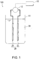
- the apparatus of Embodiment 1 is illustrated in FIG. 1 .
- the apparatus 100 of FIG. 1 includes a cell 11, a power source 12, a controller 13, and an electrode pair 20.
- the electrode pair 20 is disposed inside the cell 11.
- the cell 11 is an electrolytic cell.
- the electrode pair 20 includes a first electrode 21 and a second electrode 22.
- the power source 12 is connected to the first electrode 21 and the second electrode 22.
- Programs for executing each of the processes are stored in a storage unit of the controller 13.
- the controller 13 controls the voltage output from the power source 12 in accordance with those programs.
- An aqueous solution 30 that represents the aqueous solution (S) is stored in the cell 11.
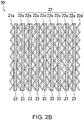
- FIG. 2A A front view of one example of the first electrode 21 is illustrated in FIG. 2A .
- the first electrode 21 of FIG. 2A includes a net-like electrode 21a and a lead 21b connected thereto.
- the second electrode 22 also includes a similar net-like electrode and a lead.
- An expanded metal coated with platinum can be used as the net-like electrodes.
- the first electrode 21 may include a plurality of net-like electrodes, and the second electrode 22 may also include a plurality of net-like electrodes. By adjusting the number of net-like electrodes within each electrode, the ratio between the surface area of the first electrode 21 and the surface area of the second electrode 22 can be altered.
- FIG. 2B illustrates an example in which the first electrode 21 includes a single net-like electrode 21a, and the second electrode 22 includes 9 net-like electrodes 22a. Spacers 23 are disposed between the net-like electrodes, and the net-like electrodes and spacers 23 are stacked against each other. Leads are omitted in FIG. 2B , but the 9 net-like electrodes 22a are connected by leads. In the example in FIG. 2B , the net-like electrode 21a and the net-like electrodes 22a are not disposed alternately, but the two electrodes may also be disposed alternately.
- the controller 13 executes process (i).
- process (i) a DC voltage is applied between the electrodes so that the first electrode 21 becomes the anode and the second electrode 22 becomes the cathode.
- the voltage at this time is a voltage that causes the concentration of free chlorine to increase, and is, for example, a voltage of at least 4 V (in one example a voltage within a range from 5 V to 12 V), or a voltage of at least 7 V (in one example a voltage within a range from 7 V to 9 V).
- an oxygen gas production reaction caused by the electrolysis of water, and a production reaction for chlorine molecules due to chloride ion oxidation (2Cl - ⁇ Cl 2 + 2e - ) occur at the surface of the anode (the first electrode 21). A portion of the produced chlorine molecules become hypochlorous acid and hypochlorite ions.
- a hydrogen gas production reaction caused by the electrolysis of water, and a free chlorine decomposition reaction occur at the surface of the cathode (the second electrode 22).
- the decomposition reaction of free chlorine includes a decomposition reaction of hypochlorous acid and a reduction reaction of chlorine molecules, as shown below. HClO + H + + 2e - ⁇ Cl - + H 2 O Cl 2 + 2e - ⁇ 2Cl -
- aqueous solution 30 treated by process (i) can be used for sterilization (for example, sterilized washing) as required.
- process (ii) a DC voltage is applied between the electrode 21 and electrode 22 so that one of the electrodes becomes the anode and the other becomes the cathode.
- the voltage may be applied so that the first electrode 21 becomes the anode and the second electrode 22 becomes the cathode.
- the voltage may be applied so that the first electrode 21 becomes the cathode and the second electrode 22 becomes the anode.
- the voltage at this time is a voltage that causes the concentration of free chlorine to decrease, and is, for example, a voltage of not more than 3 V (in one example a voltage within a range from 0.9 V to 3.0 V), or a voltage of not more than 1.8 V (in one example a voltage within a range from 1.2 V to 1.8 V).
- process (ii) In a similar manner to the voltage application of process (i), upon the voltage application in process (ii), free chlorine is produced at the anode and free chlorine is eliminated at the cathode.
- process (ii) by applying a lower voltage than that used in process (i), the elimination rate of free chlorine can be adjusted to exceed the production rate of free chlorine.
- process (ii) the concentration of free chlorine decreases upon application of the voltage.
- the aqueous solution (S) for which the concentration of free chlorine has been reduced by process (ii) may be discarded, used for washing the sterilization target, or used for some other application.
- FIG. 3 The reason that the concentration of free chlorine is able to be controlled by the magnitude of the applied voltage is currently not completely clear. However, one possible reason is described using FIG. 3 .
- the graph of FIG. 3 is a schematic graph predicted from test results, and may differ from actuality. Further, FIG. 3 is merely a schematic representation, and takes no consideration of the ratio between the magnitudes of the voltages.
- the horizontal axis in FIG. 3 indicates the electrode potential, whereas the vertical axis in FIG. 3 indicates the reaction current.
- the oxygen gas production reaction occurs more readily at a lower potential than the chloride ion oxidation reaction (free chlorine production reaction). Accordingly, by applying a low voltage, the oxygen gas production reaction can be initiated at the anode with almost no progression of the free chlorine production reaction.
- process (ii) by adjusting the potential of the anode and the potential of the cathode (for example, by setting the DC voltage applied between the two electrodes to a suitable value), the elimination rate of free chlorine at the cathode can be increased to a higher rate than the production rate of free chlorine at the anode. As a result, the concentration of free chlorine can be reduced by process (ii).
- the anode in process (ii) is an electrode in which platinum exists at the surface (a platinum-coated electrode). Platinum exhibits a large difference between the overvoltage for the oxygen gas production reaction and the overvoltage for the chloride ion oxidation reaction, and therefore by using a platinum-coated electrode, the chloride ion oxidation reaction can be suppressed.
- An aqueous solution (S) having a chloride ion concentration not higher than a prescribed value is used.
- an aqueous solution (S) having a low chloride ion concentration By using an aqueous solution (S) having a low chloride ion concentration, the chloride ion oxidation reaction can be suppressed.
- an aqueous solution having a chloride ion concentration of not more than 582 mmol/L may be used, and for example, an aqueous solution having a chloride ion concentration within a range from 17 mmol/L to 582 mmol/L (or within a range from 86 mmol/L to 205 mmol/L in one example) may be used.
- the concentration may be within a range from 0.1 wt% to 3.4 wt% (or within a range from 0.5 wt% to 1.2 wt% in one example).
- the flow rate of the aqueous solution (S) in the vicinity of the anode is increased, thereby promoting the diffusion of hydrogen ions in the vicinity of the anode.
- the average flow rate of the aqueous solution (S) flowing through the inside the electrolytic cell may be set to a value of at least 3.5 mm/s, or at least 6 mm/s. Although there are no particular limitations on the upper limit for the average flow rate, a value of not more than 30 mm/s may be used.
- the anode is moved, thereby agitating the aqueous solution (S) in the vicinity of the anode and promoting the diffusion of hydrogen ions in the vicinity of the anode. For example, by rotating the anode, the aqueous solution (S) in the vicinity of the anode can be agitated.
- J3-3 A structure that causes turbulence flow in the vicinity of the anode is used, thereby agitating the aqueous solution (S) in the vicinity of the anode and promoting the diffusion of hydrogen ions in the vicinity of the anode.
- turbulence may be generated by providing unevenness on the surface of the anode. Further, turbulence may also be generated in the vicinity of the anode by the spacers disposed between the electrodes.
- the curve for the chloride ion oxidation reaction can be moved as illustrated by the alternate long and short dash line A in FIG. 3 .
- the concentration of free chlorine can be efficiently reduced in process (ii).
- An effect can be achieved by implementing any one of the above conditions (J1) to (J3), but the effect can be enhanced by combining a plurality of the conditions. Specifically, combinations of (J1) and (J2), (J1) and (J3), (J2) and (J3), or (J1), (J2) and (J3) may be satisfied. Further, in addition to these conditions, condition (J4) described below may also be satisfied.
- the production rate of free chlorine at the anode can be increased so as to exceed the elimination rate of free chlorine at the cathode.
- the voltage application in process (i) enables the concentration of free chlorine to be increased.
- process (i) and process (ii) may be performed such that condition (J4) described below is satisfied.
- a DC voltage of at least 4 V (for example, within a range from 4 V to 12 V) is applied between the first anode and the first cathode, and in process (ii), a DC voltage within a range from 0.6 V to 3 V is applied between the second anode and the second cathode.
- a DC voltage of at least 5 V (for example, within a range from 5 V to 8 V) is applied in process (i)
- a DC voltage within a range from 0.9 V to 3 V (for example, within a range from 1.2 V to 3 V) is applied in process (ii).
- the potential difference between the electrodes may be altered as the treatment progresses.
- a DC voltage within a range from 1.8 to 3.0 V may be applied between the electrodes, and then when the concentration of free chlorine decreases to 50 mg/L, a DC voltage of at least 1.2 V but less than 1.8 V may be applied.
- the rate of reduction in the concentration of free chlorine may sometimes be able to be increased.
- At least one condition selected from the group consisting of (J1), (J2), (J3) and (J4) may be satisfied.
- processes (i) and (ii) may be performed in such a manner that all of (J1) to (J4) are satisfied.
- process (ii) maybe replaced with a process (ii').
- process (ii') the concentration of free chlorine in the aqueous solution (S) is reduced by applying a DC voltage between two electrodes selected from the plurality of electrodes, in a state where at least one condition selected from the group consisting of (J1), (J2), (J3) and (J4) is satisfied.
- the anode and the cathode in process (i), and the anode and the cathode in process (ii) may all be electrodes in which platinum exists at the electrode surface, and the above condition (J4) may be satisfied.
- an aqueous solution (S) having a chloride ion concentration within a range from 17 mmol/L to 582 mmol/L (or within a range from 86 mmol/L to 205 mmol/L in one example) may be used.
- the average flow rate of the aqueous solution (S) flowing around the periphery of the anode and the cathode in process (ii) may be at least 3.5 mm/s.
- the average flow rate of the aqueous solution (S) inside the cell in which the anode and the cathode are disposed can be considered as the average flow rate of the aqueous solution (S) flowing around the periphery of the anode and the cathode.
- One method of increasing the average flow rate of the aqueous solution (S) flowing through the electrolytic cell involves reducing the cross-sectional area (C) of the electrodes, the cross-sectional area (C) being perpendicular to the direction of flow of the aqueous solution (S). If the amount of the aqueous solution (S) flowing through the electrolytic cell per unit of time is the same, then the smaller the cross-sectional area (C) becomes, the faster the average flow rate of the aqueous solution (S) flowing through the electrolytic cell will become.
- the electrolytic cell and the electrodes disposed therein may be formed as elongated rectangular shapes, with the aqueous solution (S) then set to flow along the lengthwise direction.
- the average flow rate of the aqueous solution (S) flowing through the electrolytic cell may be set to different values in process (i) and process (ii). Specifically, the aforementioned average flow rate in process (i) may be slower than the average flow rate in process (ii). By slowing the average flow rate in process (i), the electric double layer at the electrode surface can be maintained, and the concentration of free chlorine can be increased efficiently. On the other hand, by increasing the average flow rate in process (ii), as described above, the concentration of free chlorine can be efficiently reduced in process (ii).
- Examples of the method for altering the average flow rate between process (i) and process (ii) include the following three methods.
- a first method the pump and valves are simply adjusted to alter the amount of the aqueous solution (S) flowing through the electrolytic cell per unit of time. This configuration illustrated below in FIG. 5 is included in this first method.
- a rectangular electrolytic cell and a rectangular electrode group disposed inside the cell are used, and the direction in which the aqueous solution (S) flows is altered between process (i) and process (ii).
- the aqueous solution (S) is set to flow in a direction perpendicular to the direction in which the cross-sectional area of the electrolytic cell is larger in process (i), and set to flow in a direction perpendicular to the direction in which the cross-sectional area of the electrolytic cell is smaller in process (ii).
- the electrolytic cell is altered between process (i) and process (ii). In this case, a plurality of electrolytic cells having different cross-sectional areas are used.
- Embodiment 2 examples of the method and apparatus for circulating the aqueous solution (S) between an electrolytic cell and a region outside the electrolytic cell are described.
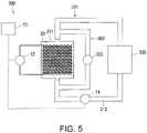
- An apparatus 200 of Embodiment 2 is illustrated in FIG. 4 .
- the apparatus 200 includes a cell 211, a power source 12, a controller 13, a pump 14, and an electrode pair 20.
- the electrode pair 20 is disposed inside the cell 211.
- the cell 211 is an electrolytic cell.
- the power source 12, the controller 13 and the electrode pair 20 were described above in Embodiment 1, and duplicate descriptions of these items are omitted.
- FIG. 4 illustrates an example in which the electrode pair 20 illustrated in FIG. 2B is used.
- An inlet 211a and an outlet 211b are formed in the cell 211.
- a passage 212 is connected between the inlet 211a and the outlet 211b so as to form a circulation passage 301 including a sterilization target 300.
- the aqueous solution 30 that represents the aqueous solution (S) is circulated through the circulation passage 301 by the pump 14 under the control of the controller 13.
- a passage or tank for supplying the aqueous solution 30, and a passage or tank for discharging the aqueous solution 30 following its use in the sterilization may also be connected to the circulation passage 301.
- the inlet 211a and the outlet 211b are formed, and as illustrated in FIG. 4 , the inlet 211a may be formed at the bottom of the cell 211 and the outlet 211b formed at the top of the cell 211.
- gas that is produced at the surfaces of the electrodes can be removed rapidly from the electrode surfaces. As a result, any deterioration in the rate of the electrolysis reaction due to gas on the surfaces of the electrodes can be suppressed.
- the net-like electrodes may be disposed so that the in-plane direction of the net-like electrodes is orthogonal to the flow of the aqueous solution 30.
- the first electrode 21 having a small surface area may be disposed on the side of the inlet 211a, and process (ii) may be performed with a voltage applied such that the first electrode 21 becomes the anode.
- process (I) (the sterilization process including process (i)) is performed in a state where the aqueous solution 30 is circulated between the cell 211 and the sterilization target 300.
- process (II) (the washing process including process (ii)) may also be performed in a state where the aqueous solution 30 is circulated between the cell 211 and the sterilization target 300.
- Process (i) and process (ii) can be executed using the same method as that described for Embodiment 1.
- the sterilization target 300 is tubing.
- the apparatus 200 sterilized washing of the inside of the tubing can be achieved.
- the tubing include the tubing of a blood treatment apparatus.
- the tubing through which the dialysis fluid passes requires sterilization after use.
- the concentration of residual free chlorine in the tubing requires to be reduced before dialysis can be restarted.
- the inside of the tubing can be subjected to sterilized washing by process (I), and the concentration of free chlorine inside the tubing can then be reduced by process (II). Accordingly, the present invention can be used favorably for sterilization of the tubing inside a blood treatment apparatus.
- the sterilization may be performed by providing a sterilization tank at the position of the sterilization target 300, and then immersing the articles that are to be subjected to sterilized washing in the aqueous solution (S) inside that sterilization tank. Further, the cell 11 of Embodiment 1 may be used as the sterilization tank.
- the voltage application times during process (i) and process (ii) may be set in accordance with the desired purpose.
- a sensor for monitoring the concentration of free chlorine may be placed inside the cell or inside the flow passage.
- the controller may control the magnitude of the voltage and the time of the voltage application based on the output from the sensor. Further, the controller may also apply the voltage in accordance with predetermined conditions.
- the apparatus may be constructed so that the cell 211 forms a part of two circulation passages.
- a circulation passage 302 is formed in parallel with the circulation passage 301.
- the flow volume of the aqueous solution (S) through the circulation passage 302 is controlled by a pump 303 provided within the circulation passage 302.
- the flow rate (average flow rate) of the aqueous solution (S) inside the cell 211 can be increased independently of the flow rate of the aqueous solution (S) through the circulation passage 301.
- the concentration of free chlorine was measured by the DPD method (diethyl-para-phenylenediamine method). Specifically, measurement was performed by a free chlorine measurement method (Method 8021 described by Hach Company) using an absorption photometer (DR3900) manufactured by Hach Company. In this method, the sample and a reagent for measuring the concentration of free chlorine are placed in a sample cell, and the concentration of free chlorine is calculated by measuring the absorbance of the sample which has developed color due to the reagent.
- DPD method diethyl-para-phenylenediamine method
- Example 1 the relationship between the applied voltage in process (i) and the concentration of free chlorine was investigated.
- Example 1 an electrode pair having the configuration illustrated in FIG. 2B was used. Electrodes (length: 35 mm, width: 54 mm, thickness: 1.8 mm) formed from titanium expanded metal that had been plated with platinum were used for the net-like electrodes that formed the anode and the cathode. As illustrated in FIG. 2B , the first electrode 21 (the anode in this example) was prepared using a single net-like electrode 21a, whereas the second electrode 22 (the cathode in this example) was prepared using 9 net-like electrodes 22a. With the electrodes in Example 1, the surface area of the cathode was about 9 times the surface area of the anode. Net-like resin spacers (thickness: 0.8 mm) were disposed between each of the electrodes.
- an aqueous solution of sodium chloride (physiological saline solution) with a concentration of 0.9 wt% was prepared.
- This aqueous solution was subjected to process (i). Specifically, the electrodes described above were placed in a beaker containing the aqueous solution, and a DC voltage was applied between the first electrode 21 (anode) and the second electrode 22 (cathode). The voltage application was performed while the aqueous solution was stirred with a stirrer. Further, the aqueous solution inside the beaker was circulated at a flow rate of 150 mL/minute using a pump. The total volume of the aqueous solution was 1 L. In Example 1, four types of tests were performed using different voltage application methods. Specifically, the voltage was applied under the four sets of conditions described below.
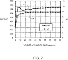
- FIG. 7 the changes in the ORP (oxidation reduction potential) and the pH of the aqueous solution when a voltage of 5 V was applied are illustrated in FIG. 7 .
- the ORP and the pH increased in the initial stages of voltage application, but were then substantially constant thereafter.
- Example 2 the relationship between the applied voltage in process (ii) and the concentration of free chlorine was investigated. In Example 2, with the exception of altering the applied voltage, tests were performed under the same conditions as Example 1.
- Example 2 a voltage was first applied for 15 minutes so that a constant current of 2 A flowed between the first electrode 21 (anode) and the second electrode 22 (cathode) described in Example 1 (process (i)).
- the voltage application in process (i) caused the concentration of free chlorine in the aqueous solution (physiological saline solution) to reach about 200 mg/L (specifically, within a range from 181 to 251 mg/L).
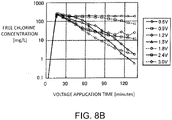
- Example 2 7 tests were performed with different applied voltages. Specifically, tests were performed in which the fixed voltage applied between the first electrode 21 (anode) and the second electrode 22 (cathode) was set to 0.6 V (Test 2-1), 0.9 V (Test 2-2), 1.2 V (Test 2-3), 1.5 V (Test 2-4), 1.8 V (Test 2-5), 2.4 V (Test 2-6) and 3.0 V (Test 2-7). Then, the relationship between the concentration of free chlorine in the aqueous solution and the voltage application time was investigated. The measurement results are illustrated in FIG. 8A . Further, a graph in which the vertical axis of FIG. 8A has been displayed as a logarithmic scale is illustrated in FIG.
- FIG. 8A and FIG. 8B the voltage application time from 0 to 15 minutes corresponds with process (i), and the subsequent time period corresponds with process (ii).
- the voltages shown in the legends of FIG. 8A and FIG. 8B represent the voltages applied in process (ii).
- the concentration of free chlorine decreased as a result of performing process (ii).
- the concentration of free chlorine decreased greatly when the applied voltage was within a range from 0.9 to 3.0 V, and decreased even more when the applied voltage was within a range from 1.2 to 3.0 V (and particularly within a range from 1.2 V to 1.8 V).
- the salt concentration in the aqueous solution was high, setting the applied voltage within a range from 1.8 V to 3.0 V enabled the rate of reduction in the concentration of free chlorine to be increased.
- FIG. 9 The changes in the ORP and the pH of the aqueous solution in Test 2-5 (an applied voltage of 1.8 V in process (ii)) are illustrated in FIG. 9 .
- an applied voltage of 1.8 V in process (ii) is illustrated in FIG. 9 .
- the ORP increased and the pH decreased in the period when the voltage application time shown in FIG. 9 was between 15 minutes (the start of process (ii)) and 30 minutes, but after that period, there was no significant change in either property.
- Example 3 tests were performed in which the ratio between the surface area of the anode and the surface area of the cathode was altered.
- the second electrode 22 described in Example 1 namely an electrode containing 9 net-like electrodes 22a
- the net-like electrode of the anode the net-like electrode 21a described in Example 1 was used, but the number of these net-like electrodes constituting the anode was varied from one to nine.
- the configurations of the electrodes used in Example 3 are shown in Table 1. As shown in Table 1, the value of (surface area of cathode)/(surface area of anode) was altered within a range from 1.0 (Test 3-5) to 9.0 (Test 3-1).
- Example 3 With the exception of changing the configuration of the electrode pair, tests were performed under the same conditions as Test (2-3) of Example 2. Specifically, a voltage was first applied for 15 minutes so that a constant current of 2 A flowed between the anode (the first electrode 21) and the cathode (the second electrode 22) (process (i)). The voltage application in process (i) caused the concentration of free chlorine to reach about 200 mg/L (specifically, within a range from 194 to 251 mg/L).
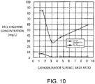
- process (ii) of any of Tests 3-1 to 3-5 was performed. Specifically, a constant voltage of 1.2 V was applied between the anode (the first electrode 21) and the cathode (the second electrode 22). Then, the change in the concentration of free chlorine in the aqueous solution as a result of process (ii) was measured. The measurement results are illustrated in FIG. 10 . As illustrated in FIG. 10 , at a point 60 minutes after the start of the voltage application of process (ii), the concentration of free chlorine had decreased greatly in those cases where the cathode/anode surface area ratio was within a range from 3.0 to 9.0.
- results in FIG. 10 indicate that by setting the cathode/anode surface area ratio within a range from 3.0 to 9.0, the rate of reduction in the concentration of free chlorine can be increased. Further, the results in FIG. 10 also indicate that in those cases where the voltage is applied for a long period of time, the concentration of free chlorine can be reduced satisfactorily even when the cathode/anode surface area ratio is large (namely, even if the area of anode used is small).
- Example 4 the relationship between the concentration of the alkali metal chloride in the aqueous solution and the change in the concentration of free chlorine was investigated. Specifically, processes (i) and (ii) were performed using different concentrations of the alkali metal chloride in the aqueous solution.
- the electrode pair used had the same configuration as the electrode pair of Example 1.
- a plurality of aqueous solutions having different concentrations of sodium chloride were prepared. Specifically, a plurality of aqueous solution of sodium chloride having concentrations within a range from 0.7 wt% to 10.8 wt% were prepared. Process (i) was performed using each of these aqueous solution of sodium chloride. Specifically, the electrode pair described above was placed in a beaker containing 200 mL of the aqueous solution, and a voltage was applied for 3 minutes so that a constant current of 2 A flowed between the first electrode 21 (anode) and the second electrode 22 (cathode). The voltage application was performed while the aqueous solution was stirred with a stirrer. As a result of this voltage application, the concentration of free chlorine in the aqueous solution reached about 200 mg/L.
- process (ii) was performed.
- a constant voltage of 1.2 V was applied between the first electrode 21 (anode) and the second electrode 22 (cathode).
- the change in the concentration of free chlorine due to process (ii) was measured.
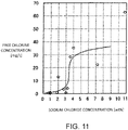
- the concentration of free chlorine after process (ii) is illustrated in FIG. 11 .
- the sodium chloride concentration and the length of time of the voltage application in process (ii) were as shown in Table 2.
- Test 4-12 Sodium chloride concentration (wt%) Voltage application time (minutes) Test 4-1 0.7 40 Test 4-2 0.9 30 Test 4-3 0.9 40 Test 4-4 1.8 50 Test 4-5 2.0 60 Test 4-6 2.7 Test 4-7 3.0 Test 4-8 3.2 Test 4-9 3.6 Test 4-10 4.0 Test 4-11 7.2 Test 4-12 10.8
- the concentration of free chlorine decreased greatly when the chloride ion concentration was within a range from 120 mmol/L to 548 mmol/L (and particularly within a range from 120 mmol/L to 514 mmol/L).
- Example 5 the anode was changed, and the same tests as Example 4 were performed.
- the concentration of the aqueous solution of sodium chloride was varied within a range from 0.9 wt% to 3.6 wt% (specifically, 0.9 wt%, 1.35 wt%, 1.8 wt% and 3.6 wt%), and the voltage application was performed for 60 minutes in process (ii).
- tests were performed under the same conditions as those described for Example 4.
- Example 5 an electrode in which iridium oxide existed at the electrode surface was used as the first electrode 21 (anode). Specifically, an electrode (JP-330) manufactured by De Nora Permelec Ltd. was used. With the exception of the anode, the remaining portions of the electrode pair had the same configuration as the electrode pair of Example 1.
- Example 5 The results of Example 5 are illustrated in FIG. 12 .
- the results of Example 4 are also shown for the purpose of comparison.
- the concentration of free chlorine decreased greatly when the sodium chloride concentration was lower than about 1.5 wt%.
- the concentration of free chlorine decreased greatly when the sodium chloride concentration was lower than about 3.4 wt%.
- Example 6 a flow-type electrolytic cell similar to the electrolytic cell 211 illustrated in FIG. 4 was used, and tests were conducted to increase and decrease the concentration of free chlorine.
- the same electrode pair as that used in Example 1 was used.
- aqueous solution an aqueous solution of sodium chloride (physiological saline solution) with a concentration of 0.9 wt% was used, and 200 mL of this aqueous solution was circulated through a circulation passage including the electrolytic cell.
- Process (i) and (ii) were performed in this state.
- a voltage was applied for 4 minutes so that a constant current of 2 A flowed between the first electrode 21 (anode) and the second electrode 22 (cathode). This voltage application caused the concentration of free chlorine in the aqueous solution to reach about 200 mg/L.
- a voltage of 1.2 V was applied for 60 minutes between the first electrode 21 (anode) and the second electrode 22 (cathode).
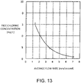
- Example 6 processes (i) and (ii) were performed with the average flow volume of the aqueous solution through the inside of the electrolytic cell set to 150 mL/minute, 400 mL/minute and 800 mL/minute. Conversion of these flow volumes to average flow rates inside the electrolytic cell yields corresponding flow rates of 1.3 mm/s, 3.5 mm/s and 7.1 mm/s respectively.
- the concentration of free chlorine after the voltage application of process (ii) is illustrated in FIG. 13 . As illustrated in FIG. 13 , a tendency was observed for a greater reduction in the concentration of free chlorine when the flow rate was faster. Specifically, the concentration of free chlorine decreased greatly when the flow rate was 3.5 mm/s or more.
- Example 7 describes an example in which the surface area of the second cathode was set to a larger value than the surface area of the first cathode.
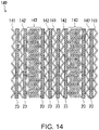
- the configuration of the electrode unit 140 used in Example 7 is illustrated schematically in FIG. 14 . Further, the electrolytic cell used in Example 7 is illustrated schematically in FIG. 15 .
- the electrode unit 140 of FIG. 14 includes a first electrode 141, a second electrode 142, a third electrode 143 and spacers 23.
- the first to third electrodes 141 to 143 are each composed of the same types of net-like electrodes. However, the number of net-like electrodes within each of the electrodes differs.
- the first electrode 141 was formed of 3 net-like electrodes.
- the second electrode 142 was formed of 4 net-like electrodes.
- the third electrode 143 was formed of 22 net-like electrodes. In FIG. 14 and FIG. 15 , in order to simplify the illustrations, the number of net-like electrodes constituting the third electrode 143 has been reduced.
- each net-like electrode a platinum-coated electrode having a size of 80 mm ⁇ 60 mm and a thickness of 0.5 mm was used.
- Each spacer used a resin net-like spacer having a size of 80 mm ⁇ 60 mm and a thickness of 0.5 mm.
- the electrode unit 140 was positioned inside the cell 211 so that each of the net-like electrodes was parallel to the flow direction of the aqueous solution.
- a circulation passage including the inlet 211a and the outlet 211b was formed, and 1.5 L of saline solution was circulated through this circulation passage.
- a solution having a concentration of free chlorine of about 240 to 250 ppm (about 240 to 250 mg/L) and a concentration of NaCl of 0.65 wt% was used.
- the flow volume of the saline solution through the circulation passage was set to 0.3 L/minute. Process (ii) was performed in a state where the saline solution was being circulated.
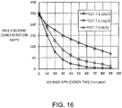
- Example 7 process (ii) was performed with various values for the ratio between the surface area of the second anode and the surface area of the second cathode.
- the electrode surface area ratio in each of the tests is shown in Table 3. [Table 3] Number of net-like electrodes Surface area ratio second cathode/second anode Second cathode Second anode Test 7-1 26 3 26/3 Test 7-2 16 3 16/3 Test 7-3 4 3 4/3
- the first electrode 141 of the electrode unit 140 was used as the second anode, and the second electrode 142 and third electrode 143 were used as the second cathode.
- (surface area of second cathode)/(surface area of second anode) 26/3.
- the surface area of the second cathode was about 9 times that of the surface area of the second anode.
- the first electrode 141 was used as the second anode
- the second electrode 142 was used as the second cathode
- no voltage was applied to the third electrode 143.
- Test 7-2 with the exception of altering the number of net-like electrodes that constitute the third electrode 143 of the electrode unit 140 to 12, testing was performed in the same manner as Test 7-1.
- the electrode unit was thinner as a result of reducing the number of net-like electrodes that constitute the third electrode 143, thus generating space inside the cell 211.
- a spacer 23 was positioned in that space.
- process (i) may be conducted without applying a voltage to the third electrode 143.
- process (i) may be performed using the first electrode 141 as the first anode and the second electrode 142 as the first cathode.
- Example 8 process (i) and process (ii) were performed, and the change in the concentration of free chlorine was measured.
- process (ii) of Example 8 the voltage applied between the electrodes was reduced in a stepwise manner.
- Example 8 the same electrode unit and circulation passage as those used in Test 7-1 of Example 7 were used. A saline solution having a concentration of NaCl of 0.65 wt% was circulated through the circulation passage, and processes (i) and (ii) were performed in that state.
- process (i) a DC voltage of 6 V was applied between the first anode and the first cathode.
- the magnitude of the DC voltage applied between the second anode and the second cathode was initially set to 2 V, and was subsequently reduced to 1.5 V, and then to 1.2 V.
- the change in the concentration of free chlorine is illustrated in FIG. 17A .
- a partial enlargement of FIG. 17A is shown in FIG. 17B .
- the final concentration of free chlorine was able to be reduced to 1 ppm or less.
- the concentration of free chlorine was able to be reduced to an extremely low level in a short period of time.
- the present invention can be used in a method and apparatus for controlling the concentration of free chlorine, and can also be used in a sterilization method and sterilization apparatus using said method and apparatus.
Landscapes
- Chemical & Material Sciences (AREA)
- Engineering & Computer Science (AREA)
- Chemical Kinetics & Catalysis (AREA)
- Health & Medical Sciences (AREA)
- Electrochemistry (AREA)
- Organic Chemistry (AREA)
- Life Sciences & Earth Sciences (AREA)
- General Chemical & Material Sciences (AREA)
- Materials Engineering (AREA)
- Metallurgy (AREA)
- General Health & Medical Sciences (AREA)
- Veterinary Medicine (AREA)
- Public Health (AREA)
- Animal Behavior & Ethology (AREA)
- Epidemiology (AREA)
- Automation & Control Theory (AREA)
- Water Supply & Treatment (AREA)
- Environmental & Geological Engineering (AREA)
- Hydrology & Water Resources (AREA)
- Inorganic Chemistry (AREA)
- Analytical Chemistry (AREA)
- Water Treatment By Electricity Or Magnetism (AREA)
- Electrolytic Production Of Non-Metals, Compounds, Apparatuses Therefor (AREA)
- Apparatus For Disinfection Or Sterilisation (AREA)
- Electrodes For Compound Or Non-Metal Manufacture (AREA)
Claims (10)
- Procédé pour réguler la concentration de chlore libre en utilisant une pluralité d'électrodes, le procédé comprenant, dans l'ordre :un premier processus (i) de réglage d'un potentiel d'une anode et d'un potentiel d'une cathode dans une solution aqueuse (30) qui comprend des ions de chlore, ce qui permet d'augmenter une concentration de chlore libre dans la solution aqueuse (30) ;caractérisé par :un second processus (ii) de réglage du potentiel d'une anode et du potentiel d'une cathode dans la solution aqueuse (30), ce qui permet de diminuer une concentration de chlore libre dans la solution aqueuse (30) ; dans lequel :une tension continue/DC qui est appliquée entre l'anode et la cathode lors du second processus (ii) présente une amplitude qui est inférieure à celle d'une tension continue/DC qui est appliquée entre l'anode et la cathode lors du premier processus (i) ;l'anode respective est constituée par une première partie respective de la pluralité d'électrodes ;la cathode respective est constituée par une seconde partie respective de la pluralité d'électrodes ;l'anode respective et la cathode respective sont chacune des électrodes respectives dans lesquelles du platine est présent au niveau d'une surface des électrodes ou qui sont revêtues de platine ; etune tension continue/DC d'au moins 4 V est appliquée entre l'anode et la cathode lors du premier processus (i) ; etune tension continue/DC à l'intérieur d'une plage de 0,6 V à 3 V est appliquée entre l'anode et la cathode lors du second processus (ii).
- Procédé selon la revendication 1, dans lequel :une aire de surface de la cathode lors du second processus (ii) est plus grande qu'une aire de surface de la cathode lors du premier processus (i) ; etune aire de surface de la cathode lors du second processus (ii) est plus grande qu'une aire de surface de l'anode lors du second processus (ii).
- Procédé selon la revendication 1 ou 2, dans lequel :la pluralité d'électrodes comprend une première électrode (21 ; 141) qui est utilisée en tant qu'anode, une deuxième électrode (22 ; 142) qui est utilisée en tant que cathode à la fois lors du premier processus (i) et lors du second processus (ii), et une troisième électrode (143) ;une tension n'est pas appliquée sur la troisième électrode (143) lors du premier processus (i) ; etla troisième électrode (143) est utilisée en tant qu'au moins une partie de la cathode lors du second processus (ii).
- Procédé selon l'une quelconque des revendications 1 à 3, comprenant en outre, soit entre le premier processus (i) et le second processus (ii), soit après le second processus (ii) :
un autre processus (x) de réglage du potentiel d'une anode et du potentiel d'une cathode dans la solution aqueuse (30), ce qui permet de maintenir une concentration de chlore libre dans la solution aqueuse (30) à l'intérieur d'une plage fixée ; dans lequel :
l'anode et la cathode sont respectivement constituées par une partie et par une autre partie de la pluralité d'électrodes. - Procédé selon l'une quelconque des revendications 1 à 4, dans lequel :
pendant le second processus (ii), une différence entre le potentiel de l'anode et le potentiel de la cathode est réduite de façon progressive. - Appareil (100 ; 200) pour réguler la concentration de chlore libre, l'appareil (100 ; 200) comprenant :une pluralité d'électrodes ;une source d'alimentation en énergie électrique (12) pour appliquer une tension sur la pluralité d'électrodes ; etun contrôleur (13) pour commander, contrôler et réguler la source d'alimentation en énergie électrique (12) ; dans lequel :
le contrôleur est configuré pour exécuter, dans l'ordre :un premier processus (i) de réglage du potentiel d'une anode et du potentiel d'une cathode dans une solution aqueuse (30) qui comprend des ions de chlore, ce qui permet d'augmenter une concentration de chlore libre dans la solution aqueuse (30) ;caractérisé par :un second processus (ii) de réglage du potentiel d'une anode et du potentiel d'une cathode dans la solution aqueuse (30), ce qui permet de diminuer une concentration de chlore libre dans la solution aqueuse (30) ; dans lequel :une tension continue/DC qui est appliquée entre l'anode et la cathode lors du second processus (ii) présente une amplitude qui est inférieure à celle d'une tension continue/DC qui est appliquée entre l'anode et la cathode lors du premier processus (i) ;l'anode respective est constituée par une première partie de la pluralité d'électrodes ;la cathode respective est constituée par une seconde partie de la pluralité d'électrodes ;l'anode respective et la cathode respective sont chacune des électrodes dans lesquelles du platine est présent au niveau d'une surface de l'électrode ou qui sont revêtues de platine ;une tension continue/DC d'au moins 4 V est appliquée entre la première anode et la première cathode lors du premier processus (i) ; etune tension continue/DC à l'intérieur d'une plage de 0,6 V à 3 V est appliquée entre la seconde anode et la seconde cathode lors du second processus (ii). - Appareil (100 ; 200) selon la revendication 6, dans lequel :une aire de surface de la cathode lors du second processus (ii) est plus grande qu'une aire de surface de la cathode lors du premier processus (i) ; etune aire de surface de la cathode lors du second processus (ii) est plus grande qu'une aire de surface de l'anode lors du second processus (ii).
- Appareil (100 ; 200) selon la revendication 6 ou 7, dans lequel :la pluralité d'électrodes comprend une première électrode (21 ; 141) qui est utilisée en tant qu'anode, une deuxième électrode (22 ; 142) qui est utilisée en tant que cathode à la fois lors du premier processus (i) et lors du second processus (ii), et une troisième électrode (143) ;une tension n'est pas appliquée sur la troisième électrode lors du premier processus (i) ; etla troisième électrode est utilisée en tant qu'au moins une partie de la seconde cathode lors du second processus (ii).
- Appareil (100 ; 200) selon l'une quelconque des revendications 6 à 8, dans lequel soit entre le premier processus (i) et le second processus (ii), soit après le second processus (ii), le contrôleur (13) est configuré pour exécuter :
un autre processus (x) de réglage du potentiel d'une anode et du potentiel d'une cathode dans la solution aqueuse (30), ce qui permet de maintenir une concentration de chlore libre dans la solution aqueuse (30) à l'intérieur d'une plage fixée ; dans lequel :
l'anode et la cathode sont respectivement constituées par une partie et par une autre partie de la pluralité d'électrodes. - Appareil (100 ; 200) selon l'une quelconque des revendications 6 à 9, dans lequel :
pendant le second processus (ii), le contrôleur (13) est configuré pour réduire de façon progressive une différence entre le potentiel de l'anode et le potentiel de la cathode.
Applications Claiming Priority (3)
| Application Number | Priority Date | Filing Date | Title |
|---|---|---|---|
| JP2014020876 | 2014-02-06 | ||
| JP2015003886A JP6487217B2 (ja) | 2014-02-06 | 2015-01-13 | 遊離塩素濃度を制御する方法および装置、ならびにそれらを用いた殺菌方法および殺菌装置 |
| PCT/JP2015/052728 WO2015119059A1 (fr) | 2014-02-06 | 2015-01-30 | Procédé et appareil de régulation de concentration de chlore libre, et procédé et appareil de stérilisation utilisant chacun ledit procédé et ledit appareil |
Publications (3)
| Publication Number | Publication Date |
|---|---|
| EP3103771A1 EP3103771A1 (fr) | 2016-12-14 |
| EP3103771A4 EP3103771A4 (fr) | 2017-02-22 |
| EP3103771B1 true EP3103771B1 (fr) | 2022-07-20 |
Family
ID=53777866
Family Applications (1)
| Application Number | Title | Priority Date | Filing Date |
|---|---|---|---|
| EP15745808.4A Active EP3103771B1 (fr) | 2014-02-06 | 2015-01-30 | Procédé et appareil de régulation de concentration de chlore libre |
Country Status (5)
| Country | Link |
|---|---|
| US (1) | US10131555B2 (fr) |
| EP (1) | EP3103771B1 (fr) |
| JP (1) | JP6487217B2 (fr) |
| CN (1) | CN106029581B (fr) |
| WO (1) | WO2015119059A1 (fr) |
Families Citing this family (9)
| Publication number | Priority date | Publication date | Assignee | Title |
|---|---|---|---|---|
| NO20161570A1 (no) * | 2016-09-29 | 2018-03-30 | Brage Innovation As | Klorgass-felle for avliving av lakselus parasitter |
| JP6817080B2 (ja) * | 2017-01-13 | 2021-01-20 | カイゲンファーマ株式会社 | 電解用電極 |
| EP3593401B1 (fr) * | 2017-03-06 | 2025-05-21 | Evoqua Water Technologies LLC | Mise en oeuvre d'une commande par feedback en vue d'une conception améliorée d'un système électrochimique |
| IL257589A (en) * | 2018-02-18 | 2018-04-30 | Univ Bar Ilan | Method and apparatus for electrochemical ph control |
| KR102313539B1 (ko) * | 2018-11-21 | 2021-10-15 | 이연주 | 살균 전극 및 그 제작 방법 및 이를 이용한 축사 살균 장치 |
| KR102268312B1 (ko) * | 2018-12-13 | 2021-06-23 | 한양대학교 산학협력단 | 재생에너지를 이용하는 차아염소산 생산 장치 |
| JP7516010B2 (ja) * | 2019-02-20 | 2024-07-16 | 東芝ライフスタイル株式会社 | 自律型電気掃除機 |
| JP2025502967A (ja) * | 2022-01-14 | 2025-01-30 | モリアー インコーポレイテッド | 電解槽内で塩素ガスを生成するための方法および装置 |
| CN116479469B (zh) * | 2023-04-23 | 2026-04-17 | 广东美的制冷设备有限公司 | 电解控制方法、可读存储介质、电解控制装置和电解设备 |
Family Cites Families (20)
| Publication number | Priority date | Publication date | Assignee | Title |
|---|---|---|---|---|
| GB1582130A (en) * | 1976-07-13 | 1980-12-31 | Matthey Rustenburg Refines | Electrolytic treatment of effluents |
| US5256268A (en) | 1990-07-18 | 1993-10-26 | Konica Corporation | Water treatment method and apparatus |
| JP3056511B2 (ja) | 1990-07-18 | 2000-06-26 | コニカ株式会社 | 被処理水の処理装置 |
| JP3283052B2 (ja) | 1992-01-08 | 2002-05-20 | クロリンエンジニアズ株式会社 | 次亜塩素酸塩の製造方法 |
| JPH06153744A (ja) | 1992-09-25 | 1994-06-03 | Riyouyou Sangyo Kk | 魚類寄生虫および細菌の死滅と生簀網付着生物の除去方法 |
| JPH11226092A (ja) | 1998-02-12 | 1999-08-24 | Trp:Kk | 医療用具の殺菌洗浄方法およびその装置 |
| JP3951156B2 (ja) * | 1998-04-10 | 2007-08-01 | 株式会社オメガ | 殺菌洗浄水の供給方法およびその装置 |
| CN1263913C (zh) | 2000-12-04 | 2006-07-12 | 株式会社岛精机制作所 | 横向编织机 |
| US6984295B2 (en) * | 2002-02-06 | 2006-01-10 | Luxon Energy Devices Corporation | Electrolytic cell for ozone generation |
| JP4085821B2 (ja) * | 2003-01-23 | 2008-05-14 | 富士電機リテイルシステムズ株式会社 | 塩素濃度制御装置 |
| JP4371731B2 (ja) * | 2003-08-11 | 2009-11-25 | 東亜ディーケーケー株式会社 | 次亜ハロゲン酸塩発生装置および発生方法 |
| JP4596937B2 (ja) | 2005-03-02 | 2010-12-15 | 英雄 早川 | 次亜塩素酸ナトリウム塩を用いた水の浄化方法 |
| WO2007037193A1 (fr) * | 2005-09-27 | 2007-04-05 | Tanah Process Ltd. | Procédé de régulation de la concentration d'ions et appareil y afférant |
| JP4919256B2 (ja) * | 2005-10-27 | 2012-04-18 | 株式会社竹中工務店 | 循環水用塩素殺菌システム |
| KR100849618B1 (ko) * | 2007-02-26 | 2008-08-01 | 한국돌기 주식회사 | 제어된 잔류 염소의 함량을 갖는 살균력이 높은 무취생리식염수의 제조 장치 및 그 제조 방법 |
| JP4980016B2 (ja) * | 2006-09-20 | 2012-07-18 | ペルメレック電極株式会社 | 電解水噴出装置及び殺菌方法 |
| US8518233B2 (en) * | 2007-02-26 | 2013-08-27 | Chil-Young Kim | Manufacturing method of medical sterilized isotonic solution having low-concentratedly controlled free chlorine including hypochlorous acid therein |
| US8025784B2 (en) * | 2008-01-04 | 2011-09-27 | Puricore, Inc. | System and method for controlling the generation of a biocidal liquid |
| WO2010027819A2 (fr) * | 2008-08-25 | 2010-03-11 | Ceramatec, Inc | Procédés de production d'hypochlorite de sodium avec un appareil à trois compartiments contenant un anolyte basique |
| US20130125316A1 (en) * | 2010-08-02 | 2013-05-23 | Xh20 Solutions Private Limited | System and a Method for Washing, Cleaning, Disinfecting and Sanitizing Laundry Using Electrolytic Cell Having Boron-Doped Diamond Electrode |
-
2015
- 2015-01-13 JP JP2015003886A patent/JP6487217B2/ja active Active
- 2015-01-30 EP EP15745808.4A patent/EP3103771B1/fr active Active
- 2015-01-30 WO PCT/JP2015/052728 patent/WO2015119059A1/fr not_active Ceased
- 2015-01-30 US US15/116,114 patent/US10131555B2/en active Active
- 2015-01-30 CN CN201580007739.8A patent/CN106029581B/zh active Active
Also Published As
| Publication number | Publication date |
|---|---|
| CN106029581A (zh) | 2016-10-12 |
| US10131555B2 (en) | 2018-11-20 |
| CN106029581B (zh) | 2019-04-09 |
| EP3103771A1 (fr) | 2016-12-14 |
| JP2015164719A (ja) | 2015-09-17 |
| JP6487217B2 (ja) | 2019-03-20 |
| EP3103771A4 (fr) | 2017-02-22 |
| WO2015119059A1 (fr) | 2015-08-13 |
| US20170137305A1 (en) | 2017-05-18 |
Similar Documents
| Publication | Publication Date | Title |
|---|---|---|
| US10131555B2 (en) | Method and apparatus for controlling concentration of free chlorine, and sterilization method and sterilization apparatus each utilizing said method and said apparatus | |
| JP3181796B2 (ja) | 電解水製造装置 | |
| JP4627337B2 (ja) | 殺菌方法および殺菌装置 | |
| ES2377945T3 (es) | Método y aparato para producir agua con potencial de oxidación y reducción (ORP) negativo y positivo | |
| JP3181795B2 (ja) | 電解水製造装置 | |
| JP5841138B2 (ja) | 次亜塩素酸塩の電気化学的生成用システム | |
| JP3994418B2 (ja) | イオン濃度調整方法およびイオン濃度調整装置 | |
| WO2015178063A1 (fr) | Appareil de fabrication d'eau électrolysée et procédé de fabrication d'eau électrolysée utilisant celui-ci | |
| TWI652374B (zh) | 雙極電解池及電解過程執行方法 | |
| JPWO2014171383A1 (ja) | 系に保持されている水性液体のイオン濃度を低減する装置および方法、ならびにその装置を備える装置 | |
| US20230064737A1 (en) | Method and apparatus for removing specific contaminants from water in a recirculating or linear treatment system | |
| JP2012152695A (ja) | 電気分解式塩水滅菌方法及び電気分解式塩水滅菌装置 | |
| JP5796986B2 (ja) | 水処理装置及び水処理方法並びに水処理システム | |
| JP2005262003A (ja) | 廃水の脱色方法および脱色装置 | |
| RU2493108C1 (ru) | Устройство для электрохимической обработки жидкости | |
| RU2056364C1 (ru) | Установка для электрохимической обработки воды | |
| JP2002361250A (ja) | 活性水素含有水の製法 | |
| EP1394119A1 (fr) | Procede et appareil pour produire de l'ozone par electrolyse | |
| JP2021112730A (ja) | 電解水製造装置及びこれを用いる電解水の製造方法 | |
| JPH08309359A (ja) | 被処理水の電気化学的処理方法 | |
| US20240174533A1 (en) | Electrolyzed water production apparatus, and electrolyzed water production method using same | |
| EP4086230A1 (fr) | Appareil de génération d'eau de stérilisation neutre sans diaphragme | |
| JP6372793B2 (ja) | 水溶液のpHを変化させる方法および装置 | |
| AU2012201437B2 (en) | Method and apparatus for producing negative and positive oxidative reductive potential (ORP) water | |
| EP2765221A1 (fr) | Procédé électrolytique de production d'agent de blanchiment |
Legal Events
| Date | Code | Title | Description |
|---|---|---|---|
| PUAI | Public reference made under article 153(3) epc to a published international application that has entered the european phase |
Free format text: ORIGINAL CODE: 0009012 |
|
| STAA | Information on the status of an ep patent application or granted ep patent |
Free format text: STATUS: REQUEST FOR EXAMINATION WAS MADE |
|
| 17P | Request for examination filed |
Effective date: 20160902 |
|
| AK | Designated contracting states |
Kind code of ref document: A1 Designated state(s): AL AT BE BG CH CY CZ DE DK EE ES FI FR GB GR HR HU IE IS IT LI LT LU LV MC MK MT NL NO PL PT RO RS SE SI SK SM TR |
|
| AX | Request for extension of the european patent |
Extension state: BA ME |
|
| A4 | Supplementary search report drawn up and despatched |
Effective date: 20170125 |
|
| RIC1 | Information provided on ipc code assigned before grant |
Ipc: A61L 2/18 20060101ALI20170119BHEP Ipc: C25B 1/26 20060101ALI20170119BHEP Ipc: C25B 15/02 20060101ALI20170119BHEP Ipc: A61L 2/03 20060101ALI20170119BHEP Ipc: C02F 1/46 20060101AFI20170119BHEP |
|
| DAX | Request for extension of the european patent (deleted) | ||
| STAA | Information on the status of an ep patent application or granted ep patent |
Free format text: STATUS: EXAMINATION IS IN PROGRESS |
|
| RIC1 | Information provided on ipc code assigned before grant |
Ipc: C02F 1/46 20060101AFI20210602BHEP Ipc: A61L 2/18 20060101ALI20210602BHEP Ipc: C25B 1/26 20060101ALI20210602BHEP Ipc: C25B 15/02 20210101ALI20210602BHEP Ipc: A61L 2/03 20060101ALI20210602BHEP Ipc: C02F 1/467 20060101ALI20210602BHEP |
|
| 17Q | First examination report despatched |
Effective date: 20210623 |
|
| GRAP | Despatch of communication of intention to grant a patent |
Free format text: ORIGINAL CODE: EPIDOSNIGR1 |
|
| STAA | Information on the status of an ep patent application or granted ep patent |
Free format text: STATUS: GRANT OF PATENT IS INTENDED |
|
| INTG | Intention to grant announced |
Effective date: 20220216 |
|
| RIN1 | Information on inventor provided before grant (corrected) |
Inventor name: LU, RONGFU Inventor name: FUJIWARA, MASATO Inventor name: WATANABE, JUNICHI Inventor name: TANAHASHI, MASAKAZU |
|
| GRAS | Grant fee paid |
Free format text: ORIGINAL CODE: EPIDOSNIGR3 |
|
| GRAA | (expected) grant |
Free format text: ORIGINAL CODE: 0009210 |
|
| STAA | Information on the status of an ep patent application or granted ep patent |
Free format text: STATUS: THE PATENT HAS BEEN GRANTED |
|
| AK | Designated contracting states |
Kind code of ref document: B1 Designated state(s): AL AT BE BG CH CY CZ DE DK EE ES FI FR GB GR HR HU IE IS IT LI LT LU LV MC MK MT NL NO PL PT RO RS SE SI SK SM TR |
|
| REG | Reference to a national code |
Ref country code: GB Ref legal event code: FG4D |
|
| REG | Reference to a national code |
Ref country code: CH Ref legal event code: EP |
|
| REG | Reference to a national code |
Ref country code: DE Ref legal event code: R096 Ref document number: 602015079927 Country of ref document: DE |
|
| REG | Reference to a national code |
Ref country code: AT Ref legal event code: REF Ref document number: 1505455 Country of ref document: AT Kind code of ref document: T Effective date: 20220815 |
|
| REG | Reference to a national code |
Ref country code: IE Ref legal event code: FG4D |
|
| REG | Reference to a national code |
Ref country code: LT Ref legal event code: MG9D |
|
| REG | Reference to a national code |
Ref country code: NL Ref legal event code: MP Effective date: 20220720 |
|
| PG25 | Lapsed in a contracting state [announced via postgrant information from national office to epo] |
Ref country code: SE Free format text: LAPSE BECAUSE OF FAILURE TO SUBMIT A TRANSLATION OF THE DESCRIPTION OR TO PAY THE FEE WITHIN THE PRESCRIBED TIME-LIMIT Effective date: 20220720 Ref country code: RS Free format text: LAPSE BECAUSE OF FAILURE TO SUBMIT A TRANSLATION OF THE DESCRIPTION OR TO PAY THE FEE WITHIN THE PRESCRIBED TIME-LIMIT Effective date: 20220720 Ref country code: PT Free format text: LAPSE BECAUSE OF FAILURE TO SUBMIT A TRANSLATION OF THE DESCRIPTION OR TO PAY THE FEE WITHIN THE PRESCRIBED TIME-LIMIT Effective date: 20221121 Ref country code: NO Free format text: LAPSE BECAUSE OF FAILURE TO SUBMIT A TRANSLATION OF THE DESCRIPTION OR TO PAY THE FEE WITHIN THE PRESCRIBED TIME-LIMIT Effective date: 20221020 Ref country code: NL Free format text: LAPSE BECAUSE OF FAILURE TO SUBMIT A TRANSLATION OF THE DESCRIPTION OR TO PAY THE FEE WITHIN THE PRESCRIBED TIME-LIMIT Effective date: 20220720 Ref country code: LV Free format text: LAPSE BECAUSE OF FAILURE TO SUBMIT A TRANSLATION OF THE DESCRIPTION OR TO PAY THE FEE WITHIN THE PRESCRIBED TIME-LIMIT Effective date: 20220720 Ref country code: LT Free format text: LAPSE BECAUSE OF FAILURE TO SUBMIT A TRANSLATION OF THE DESCRIPTION OR TO PAY THE FEE WITHIN THE PRESCRIBED TIME-LIMIT Effective date: 20220720 Ref country code: FI Free format text: LAPSE BECAUSE OF FAILURE TO SUBMIT A TRANSLATION OF THE DESCRIPTION OR TO PAY THE FEE WITHIN THE PRESCRIBED TIME-LIMIT Effective date: 20220720 Ref country code: ES Free format text: LAPSE BECAUSE OF FAILURE TO SUBMIT A TRANSLATION OF THE DESCRIPTION OR TO PAY THE FEE WITHIN THE PRESCRIBED TIME-LIMIT Effective date: 20220720 |
|
| REG | Reference to a national code |
Ref country code: AT Ref legal event code: MK05 Ref document number: 1505455 Country of ref document: AT Kind code of ref document: T Effective date: 20220720 |
|
| PG25 | Lapsed in a contracting state [announced via postgrant information from national office to epo] |
Ref country code: PL Free format text: LAPSE BECAUSE OF FAILURE TO SUBMIT A TRANSLATION OF THE DESCRIPTION OR TO PAY THE FEE WITHIN THE PRESCRIBED TIME-LIMIT Effective date: 20220720 Ref country code: IS Free format text: LAPSE BECAUSE OF FAILURE TO SUBMIT A TRANSLATION OF THE DESCRIPTION OR TO PAY THE FEE WITHIN THE PRESCRIBED TIME-LIMIT Effective date: 20221120 Ref country code: HR Free format text: LAPSE BECAUSE OF FAILURE TO SUBMIT A TRANSLATION OF THE DESCRIPTION OR TO PAY THE FEE WITHIN THE PRESCRIBED TIME-LIMIT Effective date: 20220720 Ref country code: GR Free format text: LAPSE BECAUSE OF FAILURE TO SUBMIT A TRANSLATION OF THE DESCRIPTION OR TO PAY THE FEE WITHIN THE PRESCRIBED TIME-LIMIT Effective date: 20221021 |
|
| REG | Reference to a national code |
Ref country code: DE Ref legal event code: R097 Ref document number: 602015079927 Country of ref document: DE |
|
| PG25 | Lapsed in a contracting state [announced via postgrant information from national office to epo] |
Ref country code: SM Free format text: LAPSE BECAUSE OF FAILURE TO SUBMIT A TRANSLATION OF THE DESCRIPTION OR TO PAY THE FEE WITHIN THE PRESCRIBED TIME-LIMIT Effective date: 20220720 Ref country code: RO Free format text: LAPSE BECAUSE OF FAILURE TO SUBMIT A TRANSLATION OF THE DESCRIPTION OR TO PAY THE FEE WITHIN THE PRESCRIBED TIME-LIMIT Effective date: 20220720 Ref country code: DK Free format text: LAPSE BECAUSE OF FAILURE TO SUBMIT A TRANSLATION OF THE DESCRIPTION OR TO PAY THE FEE WITHIN THE PRESCRIBED TIME-LIMIT Effective date: 20220720 Ref country code: CZ Free format text: LAPSE BECAUSE OF FAILURE TO SUBMIT A TRANSLATION OF THE DESCRIPTION OR TO PAY THE FEE WITHIN THE PRESCRIBED TIME-LIMIT Effective date: 20220720 Ref country code: AT Free format text: LAPSE BECAUSE OF FAILURE TO SUBMIT A TRANSLATION OF THE DESCRIPTION OR TO PAY THE FEE WITHIN THE PRESCRIBED TIME-LIMIT Effective date: 20220720 |
|
| PLBE | No opposition filed within time limit |
Free format text: ORIGINAL CODE: 0009261 |
|
| STAA | Information on the status of an ep patent application or granted ep patent |
Free format text: STATUS: NO OPPOSITION FILED WITHIN TIME LIMIT |
|
| PG25 | Lapsed in a contracting state [announced via postgrant information from national office to epo] |
Ref country code: SK Free format text: LAPSE BECAUSE OF FAILURE TO SUBMIT A TRANSLATION OF THE DESCRIPTION OR TO PAY THE FEE WITHIN THE PRESCRIBED TIME-LIMIT Effective date: 20220720 Ref country code: EE Free format text: LAPSE BECAUSE OF FAILURE TO SUBMIT A TRANSLATION OF THE DESCRIPTION OR TO PAY THE FEE WITHIN THE PRESCRIBED TIME-LIMIT Effective date: 20220720 |
|
| 26N | No opposition filed |
Effective date: 20230421 |
|
| PG25 | Lapsed in a contracting state [announced via postgrant information from national office to epo] |
Ref country code: AL Free format text: LAPSE BECAUSE OF FAILURE TO SUBMIT A TRANSLATION OF THE DESCRIPTION OR TO PAY THE FEE WITHIN THE PRESCRIBED TIME-LIMIT Effective date: 20220720 |
|
| PG25 | Lapsed in a contracting state [announced via postgrant information from national office to epo] |
Ref country code: SI Free format text: LAPSE BECAUSE OF FAILURE TO SUBMIT A TRANSLATION OF THE DESCRIPTION OR TO PAY THE FEE WITHIN THE PRESCRIBED TIME-LIMIT Effective date: 20220720 |
|
| REG | Reference to a national code |
Ref country code: CH Ref legal event code: PL |
|
| PG25 | Lapsed in a contracting state [announced via postgrant information from national office to epo] |
Ref country code: LU Free format text: LAPSE BECAUSE OF NON-PAYMENT OF DUE FEES Effective date: 20230130 |
|
| REG | Reference to a national code |
Ref country code: BE Ref legal event code: MM Effective date: 20230131 |
|
| PG25 | Lapsed in a contracting state [announced via postgrant information from national office to epo] |
Ref country code: LI Free format text: LAPSE BECAUSE OF NON-PAYMENT OF DUE FEES Effective date: 20230131 Ref country code: CH Free format text: LAPSE BECAUSE OF NON-PAYMENT OF DUE FEES Effective date: 20230131 |
|
| PG25 | Lapsed in a contracting state [announced via postgrant information from national office to epo] |
Ref country code: BE Free format text: LAPSE BECAUSE OF NON-PAYMENT OF DUE FEES Effective date: 20230131 |
|
| PG25 | Lapsed in a contracting state [announced via postgrant information from national office to epo] |
Ref country code: IE Free format text: LAPSE BECAUSE OF NON-PAYMENT OF DUE FEES Effective date: 20230130 |
|
| PG25 | Lapsed in a contracting state [announced via postgrant information from national office to epo] |
Ref country code: IT Free format text: LAPSE BECAUSE OF FAILURE TO SUBMIT A TRANSLATION OF THE DESCRIPTION OR TO PAY THE FEE WITHIN THE PRESCRIBED TIME-LIMIT Effective date: 20220720 |
|
| PG25 | Lapsed in a contracting state [announced via postgrant information from national office to epo] |
Ref country code: MC Free format text: LAPSE BECAUSE OF FAILURE TO SUBMIT A TRANSLATION OF THE DESCRIPTION OR TO PAY THE FEE WITHIN THE PRESCRIBED TIME-LIMIT Effective date: 20220720 |
|
| PG25 | Lapsed in a contracting state [announced via postgrant information from national office to epo] |
Ref country code: MC Free format text: LAPSE BECAUSE OF FAILURE TO SUBMIT A TRANSLATION OF THE DESCRIPTION OR TO PAY THE FEE WITHIN THE PRESCRIBED TIME-LIMIT Effective date: 20220720 |
|
| PG25 | Lapsed in a contracting state [announced via postgrant information from national office to epo] |
Ref country code: BG Free format text: LAPSE BECAUSE OF FAILURE TO SUBMIT A TRANSLATION OF THE DESCRIPTION OR TO PAY THE FEE WITHIN THE PRESCRIBED TIME-LIMIT Effective date: 20220720 |
|
| PG25 | Lapsed in a contracting state [announced via postgrant information from national office to epo] |
Ref country code: BG Free format text: LAPSE BECAUSE OF FAILURE TO SUBMIT A TRANSLATION OF THE DESCRIPTION OR TO PAY THE FEE WITHIN THE PRESCRIBED TIME-LIMIT Effective date: 20220720 |
|
| PG25 | Lapsed in a contracting state [announced via postgrant information from national office to epo] |
Ref country code: CY Free format text: LAPSE BECAUSE OF FAILURE TO SUBMIT A TRANSLATION OF THE DESCRIPTION OR TO PAY THE FEE WITHIN THE PRESCRIBED TIME-LIMIT; INVALID AB INITIO Effective date: 20150130 |
|
| PG25 | Lapsed in a contracting state [announced via postgrant information from national office to epo] |
Ref country code: HU Free format text: LAPSE BECAUSE OF FAILURE TO SUBMIT A TRANSLATION OF THE DESCRIPTION OR TO PAY THE FEE WITHIN THE PRESCRIBED TIME-LIMIT; INVALID AB INITIO Effective date: 20150130 |
|
| PG25 | Lapsed in a contracting state [announced via postgrant information from national office to epo] |
Ref country code: TR Free format text: LAPSE BECAUSE OF FAILURE TO SUBMIT A TRANSLATION OF THE DESCRIPTION OR TO PAY THE FEE WITHIN THE PRESCRIBED TIME-LIMIT Effective date: 20220720 |
|
| PGFP | Annual fee paid to national office [announced via postgrant information from national office to epo] |
Ref country code: GB Payment date: 20260123 Year of fee payment: 12 |
|
| PGFP | Annual fee paid to national office [announced via postgrant information from national office to epo] |
Ref country code: DE Payment date: 20260121 Year of fee payment: 12 |
|
| PGFP | Annual fee paid to national office [announced via postgrant information from national office to epo] |
Ref country code: FR Payment date: 20260123 Year of fee payment: 12 |