EP3104003A2 - Construction de nacelle pour une éolienne - Google Patents
Construction de nacelle pour une éolienne Download PDFInfo
- Publication number
- EP3104003A2 EP3104003A2 EP16164721.9A EP16164721A EP3104003A2 EP 3104003 A2 EP3104003 A2 EP 3104003A2 EP 16164721 A EP16164721 A EP 16164721A EP 3104003 A2 EP3104003 A2 EP 3104003A2
- Authority
- EP
- European Patent Office
- Prior art keywords
- nacelle
- construction
- platform
- heat exchanger
- heli
- Prior art date
- Legal status (The legal status is an assumption and is not a legal conclusion. Google has not performed a legal analysis and makes no representation as to the accuracy of the status listed.)
- Granted
Links
Images


Classifications
-
- F—MECHANICAL ENGINEERING; LIGHTING; HEATING; WEAPONS; BLASTING
- F03—MACHINES OR ENGINES FOR LIQUIDS; WIND, SPRING, OR WEIGHT MOTORS; PRODUCING MECHANICAL POWER OR A REACTIVE PROPULSIVE THRUST, NOT OTHERWISE PROVIDED FOR
- F03D—WIND MOTORS
- F03D80/00—Details, components or accessories not provided for in groups F03D1/00 - F03D17/00
- F03D80/60—Cooling or heating of wind motors
-
- F—MECHANICAL ENGINEERING; LIGHTING; HEATING; WEAPONS; BLASTING
- F03—MACHINES OR ENGINES FOR LIQUIDS; WIND, SPRING, OR WEIGHT MOTORS; PRODUCING MECHANICAL POWER OR A REACTIVE PROPULSIVE THRUST, NOT OTHERWISE PROVIDED FOR
- F03D—WIND MOTORS
- F03D1/00—Wind motors with rotation axis substantially parallel to the air flow entering the rotor
- F03D1/04—Wind motors with rotation axis substantially parallel to the air flow entering the rotor having stationary wind-guiding means, e.g. with shrouds or channels
-
- F—MECHANICAL ENGINEERING; LIGHTING; HEATING; WEAPONS; BLASTING
- F03—MACHINES OR ENGINES FOR LIQUIDS; WIND, SPRING, OR WEIGHT MOTORS; PRODUCING MECHANICAL POWER OR A REACTIVE PROPULSIVE THRUST, NOT OTHERWISE PROVIDED FOR
- F03D—WIND MOTORS
- F03D80/00—Details, components or accessories not provided for in groups F03D1/00 - F03D17/00
- F03D80/80—Arrangement of components within nacelles or towers
-
- F—MECHANICAL ENGINEERING; LIGHTING; HEATING; WEAPONS; BLASTING
- F03—MACHINES OR ENGINES FOR LIQUIDS; WIND, SPRING, OR WEIGHT MOTORS; PRODUCING MECHANICAL POWER OR A REACTIVE PROPULSIVE THRUST, NOT OTHERWISE PROVIDED FOR
- F03D—WIND MOTORS
- F03D80/00—Details, components or accessories not provided for in groups F03D1/00 - F03D17/00
- F03D80/80—Arrangement of components within nacelles or towers
- F03D80/88—Arrangement of components within nacelles or towers of mechanical components
-
- F—MECHANICAL ENGINEERING; LIGHTING; HEATING; WEAPONS; BLASTING
- F05—INDEXING SCHEMES RELATING TO ENGINES OR PUMPS IN VARIOUS SUBCLASSES OF CLASSES F01-F04
- F05B—INDEXING SCHEME RELATING TO WIND, SPRING, WEIGHT, INERTIA OR LIKE MOTORS, TO MACHINES OR ENGINES FOR LIQUIDS COVERED BY SUBCLASSES F03B, F03D AND F03G
- F05B2240/00—Components
- F05B2240/10—Stators
- F05B2240/14—Casings, housings, nacelles, gondels or the like, protecting or supporting assemblies there within
-
- F—MECHANICAL ENGINEERING; LIGHTING; HEATING; WEAPONS; BLASTING
- F05—INDEXING SCHEMES RELATING TO ENGINES OR PUMPS IN VARIOUS SUBCLASSES OF CLASSES F01-F04
- F05B—INDEXING SCHEME RELATING TO WIND, SPRING, WEIGHT, INERTIA OR LIKE MOTORS, TO MACHINES OR ENGINES FOR LIQUIDS COVERED BY SUBCLASSES F03B, F03D AND F03G
- F05B2240/00—Components
- F05B2240/90—Mounting on supporting structures or systems
- F05B2240/91—Mounting on supporting structures or systems on a stationary structure
- F05B2240/916—Mounting on supporting structures or systems on a stationary structure with provision for hoisting onto the structure
-
- F—MECHANICAL ENGINEERING; LIGHTING; HEATING; WEAPONS; BLASTING
- F05—INDEXING SCHEMES RELATING TO ENGINES OR PUMPS IN VARIOUS SUBCLASSES OF CLASSES F01-F04
- F05B—INDEXING SCHEME RELATING TO WIND, SPRING, WEIGHT, INERTIA OR LIKE MOTORS, TO MACHINES OR ENGINES FOR LIQUIDS COVERED BY SUBCLASSES F03B, F03D AND F03G
- F05B2260/00—Function
- F05B2260/20—Heat transfer, e.g. cooling
-
- Y—GENERAL TAGGING OF NEW TECHNOLOGICAL DEVELOPMENTS; GENERAL TAGGING OF CROSS-SECTIONAL TECHNOLOGIES SPANNING OVER SEVERAL SECTIONS OF THE IPC; TECHNICAL SUBJECTS COVERED BY FORMER USPC CROSS-REFERENCE ART COLLECTIONS [XRACs] AND DIGESTS
- Y02—TECHNOLOGIES OR APPLICATIONS FOR MITIGATION OR ADAPTATION AGAINST CLIMATE CHANGE
- Y02E—REDUCTION OF GREENHOUSE GAS [GHG] EMISSIONS, RELATED TO ENERGY GENERATION, TRANSMISSION OR DISTRIBUTION
- Y02E10/00—Energy generation through renewable energy sources
- Y02E10/70—Wind energy
- Y02E10/72—Wind turbines with rotation axis in wind direction
-
- Y—GENERAL TAGGING OF NEW TECHNOLOGICAL DEVELOPMENTS; GENERAL TAGGING OF CROSS-SECTIONAL TECHNOLOGIES SPANNING OVER SEVERAL SECTIONS OF THE IPC; TECHNICAL SUBJECTS COVERED BY FORMER USPC CROSS-REFERENCE ART COLLECTIONS [XRACs] AND DIGESTS
- Y02—TECHNOLOGIES OR APPLICATIONS FOR MITIGATION OR ADAPTATION AGAINST CLIMATE CHANGE
- Y02E—REDUCTION OF GREENHOUSE GAS [GHG] EMISSIONS, RELATED TO ENERGY GENERATION, TRANSMISSION OR DISTRIBUTION
- Y02E10/00—Energy generation through renewable energy sources
- Y02E10/70—Wind energy
- Y02E10/728—Onshore wind turbines
-
- Y—GENERAL TAGGING OF NEW TECHNOLOGICAL DEVELOPMENTS; GENERAL TAGGING OF CROSS-SECTIONAL TECHNOLOGIES SPANNING OVER SEVERAL SECTIONS OF THE IPC; TECHNICAL SUBJECTS COVERED BY FORMER USPC CROSS-REFERENCE ART COLLECTIONS [XRACs] AND DIGESTS
- Y02—TECHNOLOGIES OR APPLICATIONS FOR MITIGATION OR ADAPTATION AGAINST CLIMATE CHANGE
- Y02T—CLIMATE CHANGE MITIGATION TECHNOLOGIES RELATED TO TRANSPORTATION
- Y02T50/00—Aeronautics or air transport
- Y02T50/60—Efficient propulsion technologies, e.g. for aircraft
Definitions
- the field is that of wind turbines and more particularly nacelle constructions for wind turbines.
- Wind turbines are known to include heli-hoist pads for the transport of components and/or personnel to or from a helicopter.
- Heli-hoist pads, and the structures that support the heli-hoist pads are often added to the wind turbine as an after thought, subsequent to completing the design of the wind turbine nacelle.
- the nacelle structures that support the heli-hoist pad and the pad itself have are not optimized for load carrying capacity, weight, accessibility, and the like.
- aspects of the invention relate to a heli-hoist pad that is incorporated into a wind turbine nacelle in a manner that is optimized for helicopter approach and positioning of a heli-hoist pad. Aspects of the invention also relate to the positioning of and structure for supporting heat exchangers within the free flow of wind outside of a nacelle in manners that provide for serviceability of the heat exchangers while also allowing for optimal positioning of a heli-hoist pad.
- a nacelle construction of a wind turbine includes a nacelle supported by a tower.
- the nacelle rotatably supports a rotor of the wind turbine and houses at least one drivetrain component and has an upper surface.
- a heli-hoist pad includes a platform and railing about at least a portion of the periphery of the platform.
- a recess in a first portion of the upper surface of the nacelle receives at least a portion of the platform such that the platform lies below a second portion of the upper surface of the nacelle that is outside of the recess.
- a nacelle construction of a wind turbine includes a nacelle supported by the tower.
- the nacelle rotatably supports a rotor of the wind turbine and houses at least one drivetrain component that generates heat when operated.
- the nacelle has a structure defined at least in part by a pair of lateral outer surfaces and an upper surface that each lie substantially parallel to the direction of wind flow when the wind turbine is in an operative position.
- At least one heat exchanger is positioned externally to the nacelle structure and is adapted to transfer heat from the at least one drivetrain component.
- a heat exchanger support structure extends laterally away from at least one of the lateral sides of the nacelle structure to position the at least one heat exchanger within wind flow passing.
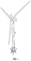
- Wind turbines such as shown in Fig. 1 , are typically constructed with a tower 10, a nacelle 12 supported on the tower, and a rotor 14 that is supported by the nacelle.
- the nacelle 12 is rotated or yawed about the tower 10 to face the rotor into the wind, so that that rotor 14 may be driven by the wind to harvest energy therefrom.
- the rotor 14 is mechanically coupled to one or more drivetrain components that may be housed within an interior of the nacelle, including one or more of a driveshaft, a gearbox, a coupling, a generator and/or a converter. These drivetrain components are used convert mechanical energy of the rotor into electrical energy to be delivered by the wind turbine.
- One or more of the drivetrain components may, in operation, produce heat that may be removed to maintain the components and/or the interior of the nacelle within particular temperature ranges.
- Heat exchangers may be positioned within the free flow of wind that passes the nacelle during wind turbine operation to provide for efficient removal of such heat.
- the heat-exchangers may be positioned and sized to optimize operation and serviceability, particularly for wind turbines with limited availability for heat exchangers to be positioned above the nacelle due to the presence of a heli-hoist pad.
- a heli-hoist pad may be positioned at an upper portion of a nacelle to allow a helicopter to deliver personnel and/or components to the wind turbine.
- Heli-hoist pads may prove beneficial for servicing wind turbines, particularly when the wind turbine is located at a difficult to reach area, such as in offshore or mountainous locations, and/or when the nacelle is located at substantial heights above the ground or sea.
- the positioning and construction of the heli-hoist pad may be optimized both in terms of its positioning with respect to the nacelle and how the heli-hoist pad is supported by structure of the nacelle.
- an optimized solution may include the platform of the heli-hoist pad located at least partially in a recess on the upper surface of the nacelle.
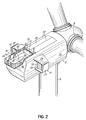
- Fig. 2 which shows a heli-hoist pad 18 positioned within a recess 20 in an upper surface 28 of a nacelle 12.
- the heli-hoist pad 18 includes a platform 22 and a railing 24.
- a first portion 36 of the platform is positioned within the recess and includes, about at least portions of three sides, a transition 26 between the recess 20 of the upper surface 28 and other portions of the upper surface 28.
- the heli-hoist pad includes a railing 24, apex of which may be higher than the adjacent upper surface 28 of the nacelle 12.
- a personnel door 30 and a service door 32 are also shown in Fig. 2 .
- the personnel door 30 provides a passageway for personnel to move between the platform 22 and an interior space of the nacelle 12.
- the service door positioned on the upper surface 28 of the nacelle, may be opened as shown in Fig. 2 to provide access into the interior of the nacelle for removal and/or replacement of drivetrain components and other equipment.
- Fig. 2 is a view of the embodiment of Fig. 1 (portions of the tower and rotor structure are omitted in Fig. 2 ) with both the personnel 30 and the service door 32 in open positions.
- a nacelle based crane 74 that is extending partially out of the service door.
- Heli-hoist pads may be positioned to provide a favorable approach for a helicopter. As is to be appreciated, certain clearance should be maintained between the rotor of an approaching helicopter and the structure of the wind turbine, including the rotor of the wind turbine. To provide for clearance and/or to allow access for a wide range of helicopter sizes, the heli-hoist pad may be positioned toward the downwind side of the nacelle, or even partially extending from the downwind end 46 of the nacelle structure, as shown in Figs. 2 and 3 . In Figs.
- the heli-hoist pad 18 includes a first portion 36, positioned directly over the nacelle (i.e., the portion of the nacelle that defines an enclosure for other components and personnel) and a second portion 38 that extends away from the nacelle and which is supported by a frame 40 that connects to other structures of the wind turbine.
- the first portion has a length (taken in the downwind-to-upwind direction of the nacelle, when in the operative position) of up to or greater than 2.0 meters, up to or greater than 2.5 meters, up to or greater than 3.0 meters, or even greater.
- the second portion of the heli-hoist pad may have lengths ranging up to or greater than 2.0 meters, up to or greater than 2.5 meters, up to or greater than 3.0 meters, or even greater. Widths of the platform may range up to 2.0 meters or greater, up to or greater than 2.5 meters, up to or greater than 3.0 meters, or even greater.
- Heli-hoist pads may be constructed to minimize impacts on the downdraft produced by the helicopter rotor and thus the helicopter itself.
- the railing 24 of the heli-hoist pad may be constructed to allow air flow from the helicopter downdraft to freely pass through therethrough, such as by being formed of vertical supports separated by air gaps, or the like.
- the platform 22 itself, or at least portions that do not lie directly over the nacelle may be constructed of a grating that allows the passage of airflow therethrough.
- Positioning of the heli-hoist pad 18 either partially or wholly aft of the downwind end 46 of the nacelle may also help minimize the impact that the structure of the heli-hoist and the nacelle itself have on the helicopter downdraft.
- the platform 22 of a heli-hoist pad 18 may be constructed to have a level and/or contiguous surface, even where the platform extends across multiple portions or includes a doorway, as in the embodiments of Figs. 2 and 3 .
- Providing a platform with a level surface may prove beneficial when personnel or items are lowered on the heli-hoist pad from above by eliminating obstacles or high spots that might otherwise need to be accommodated.
- the personnel door shown in Figs. 2 and 3 lies flush with the platform surface when closed. It is to be appreciated that other arrangements are also possible, including embodiments that lack a personnel door directly on the platform.
- the heli-hoist pad may be positioned to allow external access to equipment located inside of the nacelle.
- the upper surface of the nacelle cover includes an openable service door 32 that provides access to the interior of the nacelle.
- the service door may be positioned just upwind of the heli-hoist pad and, in this respect, may provide a good vantage point for personnel overseeing activities within the nacelle. For instance, personnel may be provided with a good view of activities within the nacelle and/or on the heli-hoist pad when operating a nacelle based crane 74 used to move components, as shown in Fig. 3 .
- the design of the heli-hoist pad may be optimized to maximize the weight of the total load that may be supported by the platform while minimizing the weight of the structure dedicated to supporting the heli-hoist pad and the heli-hoist pad itself.
- the outer surfaces of a nacelle structure are often supported by a nacelle "skeleton structure" 42 that is, in turn, supported by a base frame 43 (or other structure) that supports the entire nacelle on top of the tower 10.
- Fig. 4 is a partial cross-sectional view showing the skeleton structure that is supports the surfaces of the nacelle, and other internal support structures.
- the heli-hoist pad is not supported, or at least is only supported minimally by portions of the skeleton structure 42 that support the upper surface 28 of the nacelle.
- the support structure as shown in Fig. 4 , is directly connected to internal structures of the nacelle. Supporting the heli-hoist pad in this manner may allow the skeleton structure that supports the upper surface of the nacelle to be lighter weight. Additionally, placement of the heli-hoist pad may be lower with respect to the upper surface of the nacelle, and actually within recess as shown, may help minimize the amount and weight of material used to support the heli-hoist pad.
- the upper surface of the nacelle may include a recess 20 to receive all or a portion of the platform of a heli-hoist pad to help achieve a lower platform position.
- the upper surface 28 of the nacelle includes a recess 20 that provides for level platform mounting of the heli-hoist pad 18. The recess, as shown, extends from a transition 26 at the upwind end 44 of the recess to the downwind end 46 of the nacelle, allowing a level platform to extend across and beyond the downwind end.
- the recess also includes transitions at lateral sides of the platform that allow at least portions of three sides of the platform to set within the recess. Upwind and lateral sides of the recess may, as shown, conform to the railing or other side structure of the heli-hoist pad. In some instances, railings or portions of the railing may be provided directly by the recess itself, rather than a separate structure.
- the depth of the recess into the upper surface of the nacelle may vary, according to different embodiments.
- the apex of the upper surface of the nacelle is over a meter higher than the platform of the heli-hoist pad.
- the platform of the heli-hoist pad is in turn, approximately 1 meter higher than the supporting from within the interior of the nacelle, as shown in Fig. 4 . It is to be appreciated that these distances are merely examples, and that other embodiments may include different recess depths, including depths of 0.25 meters, 0.5 meters, 1.5 meters, and other variations.
- wind turbine nacelles typically house drivetrain components that produce heat when operated, such as gearboxes, generators, converters, transformers, and the like. The heat produced by these and/or other components may be removed through various mechanisms.
- heat exchangers 50 are positioned on lateral surfaces 52 of the nacelle in the flow of wind that passes by the nacelle 12. Positioning the heat exchanger on one or more lateral sides of the nacelle may provide several benefits, as discussed in greater detail herein.
- Positioning heat exchangers 50 externally to the nacelle 12 and in the free flow of wind that passes may provide sufficient air flow for heat removal under different operating conditions.
- the power generated by a wind turbine is proportional to the speed of the available wind.
- the amount of heat generated by drivetrain components is also, generally speaking, proportional to the amount of power that is being produced by the wind turbine, and thus also proportional to the speed of the available wind.
- Heat exchangers placed directly in the free flow of wind will reject greater amounts of heat when the wind is at greater speeds.
- heat exchangers positioned in the free flow of wind may naturally act to reject more heat as power and heat generation increase along with available wind speeds.
- the heat exchangers may operate without auxiliary fans to move air through the heat exchangers, thereby reducing the complexity and costs of the system.
- Fig. 5 shows heat exchangers positioned outside a lateral surface of the nacelle of a wind turbine, according to one embodiment.
- a heat exchanger support structure 51 holds a bank of fin and tube heat exchangers 50 facing into the free flow of wind that passes parallel to the lateral surface of the nacelle, when in the operative position (i.e., with the rotor facing into the wind).
- the support structure 51 includes an upper support arm 54, a lower support arm 56, and a connecting support arm 58. Together, each of the lateral surface 52 of the nacelle 12, the upper support arm 54, the lower support arm 56, and the connecting support 58 arm define a passageway to receive the free flow of air. It is to be appreciated that the support structure shown in Fig. 5 is but one possible construction and that others are also contemplated.
- the illustrative embodiment of Fig. 5 includes a doorway 60 that provides access between the heat exchangers 50 and the interior of the nacelle.
- a service platform 62 is positioned just outside of the doorway 60 to provide a pathway for personnel to approach and work on the heat exchangers 50.
- the platform 62 may include railings 76 and/or attachment points for the installation of safety equipment, such as safety harnesses.
- the platform, or other features of the support structure may also be constructed to allow heat exchangers to be lifted upwardly from outside of the nacelle.
- cranes nacelle based or otherwise
- helicopters may be used to lower or raise heat exchangers into position near the platform for service and/or replacement.
- a portion of the platform may not be directly underneath the upper support arm to provide a direct line upward for lowering or raising a heat exchanger.
- each bank of heat exchangers may be constructed of modules that each weight less than 80 kilograms and that are each sized to fit through the doorway that leads into the nacelle interior, according to one embodiment.
- the height of the heat exchangers and/or the distance between the upper and lower support arm may be kept to less than 3.0 meters or even less to allow service personnel to reach both the upper and lower ends of the bank of heat exchangers without the use of a ladder.
- such embodiments of heat exchangers may extend a height associated with only a single floor or level of the nacelle, despite the nacelle potentially having a height that is much greater and potentially having multiple floors located in the nacelle interior.
- Fig. 6 illustrates an alternative embodiment for positioning heat exchangers near a lateral surface of a nacelle, and for providing access to the heat exchangers for service.
- the support structure includes support arms 66 that are connected to the nacelle structure 12 with a pivotal connection 68.
- the structures act to support the heat exchangers, much like the structure of Fig. 5 , but access to and service of the heat exchangers may be accomplished by rotating the support structure about the pivotal connection 68 to bring the heat exchangers toward the lateral surface 52 of the nacelle, such as with cables that hold the support structure in position.
- the lateral surface of the nacelle may include a opening 72 that allows the support structure, including the heat exchangers, to enter the interior of the nacelle for service.
- the support arms may pivot to bring the heat exchangers next to an opening 72 at the lateral surface of the nacelle that allows personnel to reach out of the nacelle to access heat exchangers for service and/or replacement.
- support structures may be constructed in other ways that move the heat exchangers toward the lateral side of the nacelle. For instance, according to some embodiments a sliding mechanism may be used to move the heat exchangers toward or into the interior of the nacelle.
- heat exchanges may be positioned by a support structure that extends upwardly of the upper surface of the nacelle.
- the upwardly extending support structure may fold to move the heat exchanges from an operative position, where the heat exchangers are positioned substantially vertically in the free flow of wind, to a position where the heat exchangers and the support are not upwardly extending.
- the upwardly extending support may even be moved to a substantially horizontal position where such that the structure may act as a heli-hoist pad.
- a pivotal connection and cabling may be used to hold the support structure and move the structure between each of these positions, according to one embodiment.
Landscapes
- Engineering & Computer Science (AREA)
- Life Sciences & Earth Sciences (AREA)
- Sustainable Development (AREA)
- Sustainable Energy (AREA)
- Chemical & Material Sciences (AREA)
- Combustion & Propulsion (AREA)
- Mechanical Engineering (AREA)
- General Engineering & Computer Science (AREA)
- Physics & Mathematics (AREA)
- Thermal Sciences (AREA)
- Wind Motors (AREA)
Applications Claiming Priority (4)
| Application Number | Priority Date | Filing Date | Title |
|---|---|---|---|
| US201161469172P | 2011-03-30 | 2011-03-30 | |
| DKPA201170162 | 2011-04-06 | ||
| EP12712913.8A EP2691649B1 (fr) | 2011-03-30 | 2012-03-27 | Structure de nacelle pour une éolienne |
| PCT/DK2012/050091 WO2012130243A2 (fr) | 2011-03-30 | 2012-03-27 | Structure de nacelle pour une éolienne |
Related Parent Applications (2)
| Application Number | Title | Priority Date | Filing Date |
|---|---|---|---|
| EP12712913.8A Division EP2691649B1 (fr) | 2011-03-30 | 2012-03-27 | Structure de nacelle pour une éolienne |
| EP12712913.8A Division-Into EP2691649B1 (fr) | 2011-03-30 | 2012-03-27 | Structure de nacelle pour une éolienne |
Publications (3)
| Publication Number | Publication Date |
|---|---|
| EP3104003A2 true EP3104003A2 (fr) | 2016-12-14 |
| EP3104003A3 EP3104003A3 (fr) | 2017-03-29 |
| EP3104003B1 EP3104003B1 (fr) | 2020-01-01 |
Family
ID=46931997
Family Applications (2)
| Application Number | Title | Priority Date | Filing Date |
|---|---|---|---|
| EP12712913.8A Active EP2691649B1 (fr) | 2011-03-30 | 2012-03-27 | Structure de nacelle pour une éolienne |
| EP16164721.9A Active EP3104003B1 (fr) | 2011-03-30 | 2012-03-27 | Construction de nacelle pour une éolienne |
Family Applications Before (1)
| Application Number | Title | Priority Date | Filing Date |
|---|---|---|---|
| EP12712913.8A Active EP2691649B1 (fr) | 2011-03-30 | 2012-03-27 | Structure de nacelle pour une éolienne |
Country Status (5)
| Country | Link |
|---|---|
| US (2) | US9512823B2 (fr) |
| EP (2) | EP2691649B1 (fr) |
| CN (1) | CN103492712B (fr) |
| DK (2) | DK3104003T3 (fr) |
| WO (1) | WO2012130243A2 (fr) |
Cited By (1)
| Publication number | Priority date | Publication date | Assignee | Title |
|---|---|---|---|---|
| WO2020074681A1 (fr) * | 2018-10-12 | 2020-04-16 | Nissens Cooling Solutions A/S | Système de refroidissement |
Families Citing this family (24)
| Publication number | Priority date | Publication date | Assignee | Title |
|---|---|---|---|---|
| GB2487797A (en) * | 2011-02-07 | 2012-08-08 | Vestas Wind Sys As | Wind turbine rotor service platform |
| EP2705251B1 (fr) * | 2011-05-04 | 2017-01-04 | Condor Wind Energy Limited | Pont d'atterrissage d'hélicoptère |
| DK4092265T3 (da) * | 2011-05-06 | 2024-09-23 | Siemens Gamesa Renewable Energy As | Kølearrangement til en vindmølle |
| DE102013101239A1 (de) * | 2013-02-07 | 2014-08-07 | 2-B Energy Holding B.V. | Windkraftanlage |
| WO2017008817A1 (fr) * | 2015-07-16 | 2017-01-19 | Mhi Vestas Offshore Wind A/S | Ensemble panneau de refroidissement pour tour d'éolienne, et tour d'éolienne |
| IT201600087635A1 (it) * | 2016-08-26 | 2018-02-26 | Seawind Ocean Tech Ip B V | Struttura autoportante di navicella per turbine eoliche |
| CN106481512B (zh) * | 2016-12-22 | 2019-12-24 | 江苏金风科技有限公司 | 风力发电机组及用于更换其机舱内的设备的方法 |
| EP3372828A1 (fr) * | 2017-03-07 | 2018-09-12 | Adwen GmbH | Plateforme d'hélitreuillage pour centrale éolienne |
| CN107143468A (zh) * | 2017-05-03 | 2017-09-08 | 无锡风电设计研究院有限公司 | 一种风电场巡检系统 |
| EP3453867B1 (fr) * | 2017-09-06 | 2021-02-17 | Siemens Gamesa Renewable Energy A/S | Structure de plate-forme de nacelle d'éolienne |
| DK3483431T4 (da) | 2017-11-14 | 2023-10-23 | Parkwind Nv | Vindturbinearbejdsplatform |
| DK3533999T3 (da) | 2018-03-02 | 2022-12-05 | Siemens Gamesa Renewable Energy As | Kabinestruktur og en vindmølle |
| TWI730522B (zh) * | 2018-12-21 | 2021-06-11 | 丹麥商菱重維斯塔斯海上風力有限公司 | 用於風力渦輪機的直升機吊掛平台 |
| EP3902996B1 (fr) * | 2018-12-28 | 2024-02-14 | Vestas Wind Systems A/S | Éolienne à hélitreuillage et refroidisseur mobile |
| WO2020136104A1 (fr) * | 2018-12-28 | 2020-07-02 | Mhi Vestas Offshore Wind A/S | Éolienne dotée d'un appareil d'hélitreuillage et d'un refroidisseur mobile |
| US11831226B2 (en) * | 2019-01-10 | 2023-11-28 | Vestas Wind Systems A/S | Cooling of electrical generators in wind turbines |
| ES2924559T3 (es) * | 2019-07-31 | 2022-10-07 | General Electric Renovables Espana Sl | Un conjunto de góndola para una turbina eólica |
| EP4013962A1 (fr) * | 2019-08-14 | 2022-06-22 | Vestas Wind Systems A/S | Refroidisseur à panneaux de refroidissement pivotants destiné à une éolienne |
| EP4085195B1 (fr) * | 2019-12-30 | 2025-06-11 | Vestas Wind Systems A/S | Éolienne avec plateforme de service et méthode associée |
| EP4150204B1 (fr) * | 2020-05-15 | 2024-04-24 | Vestas Wind Systems A/S | Nacelle pour éolienne et procédé pour transférer des composants |
| USD1063844S1 (en) * | 2021-08-10 | 2025-02-25 | Vestas Wind Systems A/S | Wind turbine nacelle |
| USD1075673S1 (en) * | 2021-02-10 | 2025-05-20 | Vestas Wind Systems A/S | Wind turbine nacelle |
| EP4141255B1 (fr) * | 2021-08-27 | 2024-04-17 | Wobben Properties GmbH | Éolienne, procédé de montage d'un transformateur et nacelle d'éolienne |
| EP4166783A1 (fr) * | 2021-10-12 | 2023-04-19 | Siemens Gamesa Renewable Energy Innovation & Technology S.L. | Éolienne ayant une nacelle avec une ou plusieurs extensions mobiles |
Family Cites Families (16)
| Publication number | Priority date | Publication date | Assignee | Title |
|---|---|---|---|---|
| DE50008902D1 (de) | 2000-03-17 | 2005-01-13 | Gen Electric | Offshore-Windkraftanlage |
| DE20205396U1 (de) | 2001-12-29 | 2002-11-14 | Trisl, Klaus, 65197 Wiesbaden | Windmühlen-Helicopter-Landeplatz -WM-Helibase- |
| DE102006022266A1 (de) * | 2005-11-04 | 2007-05-10 | Daubner & Stommel GbR Bau-Werk-Planung (vertretungsberechtigter Gesellschafter: Matthias Stommel, 27777 Ganderkesee) | Windenergieanlage |
| AU2006338693B2 (en) * | 2006-02-27 | 2011-04-28 | Alstom Wind S.L. | Method and system for hoisting heavy parts onto a wind turbine |
| CA2722748A1 (fr) | 2008-04-30 | 2009-11-05 | Multibrid Gmbh | Habillage de la nacelle d'une eolienne |
| US8104631B2 (en) * | 2008-07-24 | 2012-01-31 | General Electric Company | Portable crane system for wind turbine components |
| WO2010026114A2 (fr) * | 2008-09-02 | 2010-03-11 | Vestas Wind Systems A/S | Nacelle d'éolienne comportant un échangeur de chaleur |
| CN102301135A (zh) * | 2009-01-30 | 2011-12-28 | 维斯塔斯风力系统集团公司 | 在顶部具有冷却器的风力涡轮机机舱 |
| CN201696234U (zh) * | 2010-06-12 | 2011-01-05 | 华锐风电科技(集团)股份有限公司 | 水平轴风力发电机组的机舱罩 |
| CN201730767U (zh) * | 2010-06-22 | 2011-02-02 | 沈阳瑞祥风能设备有限公司 | 风力发电机的机舱散热耳架装置 |
| ES2553277T3 (es) * | 2010-08-31 | 2015-12-07 | Vestas Wind Systems A/S | Turbina eólica con un sistema de transferencia de calor |
| DE102010053163A1 (de) | 2010-12-01 | 2012-06-06 | Karl Gemassmer | Wasserkraftanlage |
| CN202295334U (zh) * | 2010-12-15 | 2012-07-04 | 西门子公司 | 集成型直升机起落平台 |
| EP2469074B2 (fr) * | 2010-12-27 | 2019-05-15 | Adwen GmbH | Installation d'éolienne avec plateforme pour déchargement d'un hélicoptère |
| CN103348132B (zh) * | 2011-02-07 | 2016-02-17 | 菱重维斯塔斯海上风力有限公司 | 具有直升机平台装置的风轮机及其使用方法 |
| EP2505541B1 (fr) | 2011-03-31 | 2016-11-30 | ALSTOM Renewable Technologies | Éolienne |
-
2012
- 2012-03-27 WO PCT/DK2012/050091 patent/WO2012130243A2/fr not_active Ceased
- 2012-03-27 DK DK16164721.9T patent/DK3104003T3/da active
- 2012-03-27 US US14/008,399 patent/US9512823B2/en active Active
- 2012-03-27 CN CN201280016183.5A patent/CN103492712B/zh active Active
- 2012-03-27 DK DK12712913.8T patent/DK2691649T3/en active
- 2012-03-27 EP EP12712913.8A patent/EP2691649B1/fr active Active
- 2012-03-27 EP EP16164721.9A patent/EP3104003B1/fr active Active
-
2016
- 2016-10-28 US US15/337,194 patent/US10125745B2/en active Active
Cited By (1)
| Publication number | Priority date | Publication date | Assignee | Title |
|---|---|---|---|---|
| WO2020074681A1 (fr) * | 2018-10-12 | 2020-04-16 | Nissens Cooling Solutions A/S | Système de refroidissement |
Also Published As
| Publication number | Publication date |
|---|---|
| EP3104003A3 (fr) | 2017-03-29 |
| EP3104003B1 (fr) | 2020-01-01 |
| US10125745B2 (en) | 2018-11-13 |
| US20140219801A1 (en) | 2014-08-07 |
| DK2691649T3 (en) | 2016-07-18 |
| WO2012130243A2 (fr) | 2012-10-04 |
| EP2691649A2 (fr) | 2014-02-05 |
| CN103492712B (zh) | 2017-03-01 |
| US20170045038A1 (en) | 2017-02-16 |
| EP2691649B1 (fr) | 2016-06-01 |
| WO2012130243A3 (fr) | 2013-03-14 |
| US9512823B2 (en) | 2016-12-06 |
| DK3104003T3 (da) | 2020-02-17 |
| CN103492712A (zh) | 2014-01-01 |
Similar Documents
| Publication | Publication Date | Title |
|---|---|---|
| EP2691649B1 (fr) | Structure de nacelle pour une éolienne | |
| CN103348132B (zh) | 具有直升机平台装置的风轮机及其使用方法 | |
| EP2691650B1 (fr) | Procédés et appareils pour l'entretien d'éléments d'éolienne par l'intermédiaire d'une partie inférieure d'une tour | |
| EP2565445B1 (fr) | Chambre de transformateur pour éolienne, composant de structure d'éolienne, éolienne et procédé d'assemblage d'éolienne | |
| US9039368B2 (en) | Wind turbine nacelle with cooler top | |
| KR101699647B1 (ko) | 풍력 발전 설비 | |
| EP2391824B1 (fr) | Nacelle d'éolienne présentant un dispositif de refroidissement sur la face supérieure | |
| JP5933587B2 (ja) | ヘリコプタ昇降用発着場を有する風力発電設備 | |
| JP5957465B2 (ja) | 風力駆動式発電装置のためのハッチカバー | |
| CN102052262A (zh) | 风力涡轮机舱的构造 | |
| WO2012078494A1 (fr) | Éolienne avec une nacelle comportant un transformateur sous nacelle | |
| EP2391823B1 (fr) | Éolienne présentant un dispositif de refroidissement supérieur | |
| CN113396280A (zh) | 用于风力涡轮机的直升机升降平台 | |
| EP3139035A1 (fr) | Éolienne comprenant un plancher de service | |
| BR112021022338B1 (pt) | Método para produzir uma turbina eólica, estrutura de nacela e turbina eólica |
Legal Events
| Date | Code | Title | Description |
|---|---|---|---|
| PUAI | Public reference made under article 153(3) epc to a published international application that has entered the european phase |
Free format text: ORIGINAL CODE: 0009012 |
|
| STAA | Information on the status of an ep patent application or granted ep patent |
Free format text: STATUS: THE APPLICATION HAS BEEN PUBLISHED |
|
| AC | Divisional application: reference to earlier application |
Ref document number: 2691649 Country of ref document: EP Kind code of ref document: P |
|
| AK | Designated contracting states |
Kind code of ref document: A2 Designated state(s): AL AT BE BG CH CY CZ DE DK EE ES FI FR GB GR HR HU IE IS IT LI LT LU LV MC MK MT NL NO PL PT RO RS SE SI SK SM TR |
|
| REG | Reference to a national code |
Ref country code: DE Ref legal event code: R079 Ref document number: 602012067019 Country of ref document: DE Free format text: PREVIOUS MAIN CLASS: F03D0080800000 Ipc: F03D0080600000 |
|
| PUAL | Search report despatched |
Free format text: ORIGINAL CODE: 0009013 |
|
| AK | Designated contracting states |
Kind code of ref document: A3 Designated state(s): AL AT BE BG CH CY CZ DE DK EE ES FI FR GB GR HR HU IE IS IT LI LT LU LV MC MK MT NL NO PL PT RO RS SE SI SK SM TR |
|
| RIC1 | Information provided on ipc code assigned before grant |
Ipc: F03D 80/80 20160101ALI20170222BHEP Ipc: F03D 80/60 20160101AFI20170222BHEP |
|
| STAA | Information on the status of an ep patent application or granted ep patent |
Free format text: STATUS: REQUEST FOR EXAMINATION WAS MADE |
|
| 17P | Request for examination filed |
Effective date: 20170929 |
|
| RBV | Designated contracting states (corrected) |
Designated state(s): AL AT BE BG CH CY CZ DE DK EE ES FI FR GB GR HR HU IE IS IT LI LT LU LV MC MK MT NL NO PL PT RO RS SE SI SK SM TR |
|
| STAA | Information on the status of an ep patent application or granted ep patent |
Free format text: STATUS: EXAMINATION IS IN PROGRESS |
|
| 17Q | First examination report despatched |
Effective date: 20180328 |
|
| GRAP | Despatch of communication of intention to grant a patent |
Free format text: ORIGINAL CODE: EPIDOSNIGR1 |
|
| STAA | Information on the status of an ep patent application or granted ep patent |
Free format text: STATUS: GRANT OF PATENT IS INTENDED |
|
| INTG | Intention to grant announced |
Effective date: 20190724 |
|
| GRAS | Grant fee paid |
Free format text: ORIGINAL CODE: EPIDOSNIGR3 |
|
| GRAA | (expected) grant |
Free format text: ORIGINAL CODE: 0009210 |
|
| STAA | Information on the status of an ep patent application or granted ep patent |
Free format text: STATUS: THE PATENT HAS BEEN GRANTED |
|
| AC | Divisional application: reference to earlier application |
Ref document number: 2691649 Country of ref document: EP Kind code of ref document: P |
|
| AK | Designated contracting states |
Kind code of ref document: B1 Designated state(s): AL AT BE BG CH CY CZ DE DK EE ES FI FR GB GR HR HU IE IS IT LI LT LU LV MC MK MT NL NO PL PT RO RS SE SI SK SM TR |
|
| REG | Reference to a national code |
Ref country code: GB Ref legal event code: FG4D |
|
| REG | Reference to a national code |
Ref country code: AT Ref legal event code: REF Ref document number: 1220081 Country of ref document: AT Kind code of ref document: T Effective date: 20200115 Ref country code: CH Ref legal event code: EP |
|
| REG | Reference to a national code |
Ref country code: IE Ref legal event code: FG4D |
|
| REG | Reference to a national code |
Ref country code: DE Ref legal event code: R096 Ref document number: 602012067019 Country of ref document: DE |
|
| REG | Reference to a national code |
Ref country code: DK Ref legal event code: T3 Effective date: 20200212 |
|
| REG | Reference to a national code |
Ref country code: NL Ref legal event code: FP |
|
| REG | Reference to a national code |
Ref country code: LT Ref legal event code: MG4D |
|
| PG25 | Lapsed in a contracting state [announced via postgrant information from national office to epo] |
Ref country code: NO Free format text: LAPSE BECAUSE OF FAILURE TO SUBMIT A TRANSLATION OF THE DESCRIPTION OR TO PAY THE FEE WITHIN THE PRESCRIBED TIME-LIMIT Effective date: 20200401 Ref country code: LT Free format text: LAPSE BECAUSE OF FAILURE TO SUBMIT A TRANSLATION OF THE DESCRIPTION OR TO PAY THE FEE WITHIN THE PRESCRIBED TIME-LIMIT Effective date: 20200101 Ref country code: RS Free format text: LAPSE BECAUSE OF FAILURE TO SUBMIT A TRANSLATION OF THE DESCRIPTION OR TO PAY THE FEE WITHIN THE PRESCRIBED TIME-LIMIT Effective date: 20200101 Ref country code: FI Free format text: LAPSE BECAUSE OF FAILURE TO SUBMIT A TRANSLATION OF THE DESCRIPTION OR TO PAY THE FEE WITHIN THE PRESCRIBED TIME-LIMIT Effective date: 20200101 Ref country code: PT Free format text: LAPSE BECAUSE OF FAILURE TO SUBMIT A TRANSLATION OF THE DESCRIPTION OR TO PAY THE FEE WITHIN THE PRESCRIBED TIME-LIMIT Effective date: 20200527 Ref country code: CZ Free format text: LAPSE BECAUSE OF FAILURE TO SUBMIT A TRANSLATION OF THE DESCRIPTION OR TO PAY THE FEE WITHIN THE PRESCRIBED TIME-LIMIT Effective date: 20200101 |
|
| PG25 | Lapsed in a contracting state [announced via postgrant information from national office to epo] |
Ref country code: HR Free format text: LAPSE BECAUSE OF FAILURE TO SUBMIT A TRANSLATION OF THE DESCRIPTION OR TO PAY THE FEE WITHIN THE PRESCRIBED TIME-LIMIT Effective date: 20200101 Ref country code: GR Free format text: LAPSE BECAUSE OF FAILURE TO SUBMIT A TRANSLATION OF THE DESCRIPTION OR TO PAY THE FEE WITHIN THE PRESCRIBED TIME-LIMIT Effective date: 20200402 Ref country code: LV Free format text: LAPSE BECAUSE OF FAILURE TO SUBMIT A TRANSLATION OF THE DESCRIPTION OR TO PAY THE FEE WITHIN THE PRESCRIBED TIME-LIMIT Effective date: 20200101 Ref country code: SE Free format text: LAPSE BECAUSE OF FAILURE TO SUBMIT A TRANSLATION OF THE DESCRIPTION OR TO PAY THE FEE WITHIN THE PRESCRIBED TIME-LIMIT Effective date: 20200101 Ref country code: IS Free format text: LAPSE BECAUSE OF FAILURE TO SUBMIT A TRANSLATION OF THE DESCRIPTION OR TO PAY THE FEE WITHIN THE PRESCRIBED TIME-LIMIT Effective date: 20200501 Ref country code: BG Free format text: LAPSE BECAUSE OF FAILURE TO SUBMIT A TRANSLATION OF THE DESCRIPTION OR TO PAY THE FEE WITHIN THE PRESCRIBED TIME-LIMIT Effective date: 20200401 |
|
| REG | Reference to a national code |
Ref country code: DE Ref legal event code: R097 Ref document number: 602012067019 Country of ref document: DE |
|
| PG25 | Lapsed in a contracting state [announced via postgrant information from national office to epo] |
Ref country code: ES Free format text: LAPSE BECAUSE OF FAILURE TO SUBMIT A TRANSLATION OF THE DESCRIPTION OR TO PAY THE FEE WITHIN THE PRESCRIBED TIME-LIMIT Effective date: 20200101 Ref country code: RO Free format text: LAPSE BECAUSE OF FAILURE TO SUBMIT A TRANSLATION OF THE DESCRIPTION OR TO PAY THE FEE WITHIN THE PRESCRIBED TIME-LIMIT Effective date: 20200101 Ref country code: SK Free format text: LAPSE BECAUSE OF FAILURE TO SUBMIT A TRANSLATION OF THE DESCRIPTION OR TO PAY THE FEE WITHIN THE PRESCRIBED TIME-LIMIT Effective date: 20200101 Ref country code: SM Free format text: LAPSE BECAUSE OF FAILURE TO SUBMIT A TRANSLATION OF THE DESCRIPTION OR TO PAY THE FEE WITHIN THE PRESCRIBED TIME-LIMIT Effective date: 20200101 Ref country code: EE Free format text: LAPSE BECAUSE OF FAILURE TO SUBMIT A TRANSLATION OF THE DESCRIPTION OR TO PAY THE FEE WITHIN THE PRESCRIBED TIME-LIMIT Effective date: 20200101 Ref country code: MC Free format text: LAPSE BECAUSE OF FAILURE TO SUBMIT A TRANSLATION OF THE DESCRIPTION OR TO PAY THE FEE WITHIN THE PRESCRIBED TIME-LIMIT Effective date: 20200101 |
|
| REG | Reference to a national code |
Ref country code: CH Ref legal event code: PL |
|
| PLBE | No opposition filed within time limit |
Free format text: ORIGINAL CODE: 0009261 |
|
| STAA | Information on the status of an ep patent application or granted ep patent |
Free format text: STATUS: NO OPPOSITION FILED WITHIN TIME LIMIT |
|
| REG | Reference to a national code |
Ref country code: AT Ref legal event code: MK05 Ref document number: 1220081 Country of ref document: AT Kind code of ref document: T Effective date: 20200101 |
|
| 26N | No opposition filed |
Effective date: 20201002 |
|
| PG25 | Lapsed in a contracting state [announced via postgrant information from national office to epo] |
Ref country code: LU Free format text: LAPSE BECAUSE OF NON-PAYMENT OF DUE FEES Effective date: 20200327 |
|
| PG25 | Lapsed in a contracting state [announced via postgrant information from national office to epo] |
Ref country code: IE Free format text: LAPSE BECAUSE OF NON-PAYMENT OF DUE FEES Effective date: 20200327 Ref country code: LI Free format text: LAPSE BECAUSE OF NON-PAYMENT OF DUE FEES Effective date: 20200331 Ref country code: IT Free format text: LAPSE BECAUSE OF FAILURE TO SUBMIT A TRANSLATION OF THE DESCRIPTION OR TO PAY THE FEE WITHIN THE PRESCRIBED TIME-LIMIT Effective date: 20200101 Ref country code: AT Free format text: LAPSE BECAUSE OF FAILURE TO SUBMIT A TRANSLATION OF THE DESCRIPTION OR TO PAY THE FEE WITHIN THE PRESCRIBED TIME-LIMIT Effective date: 20200101 Ref country code: CH Free format text: LAPSE BECAUSE OF NON-PAYMENT OF DUE FEES Effective date: 20200331 |
|
| PG25 | Lapsed in a contracting state [announced via postgrant information from national office to epo] |
Ref country code: SI Free format text: LAPSE BECAUSE OF FAILURE TO SUBMIT A TRANSLATION OF THE DESCRIPTION OR TO PAY THE FEE WITHIN THE PRESCRIBED TIME-LIMIT Effective date: 20200101 Ref country code: PL Free format text: LAPSE BECAUSE OF FAILURE TO SUBMIT A TRANSLATION OF THE DESCRIPTION OR TO PAY THE FEE WITHIN THE PRESCRIBED TIME-LIMIT Effective date: 20200101 |
|
| REG | Reference to a national code |
Ref country code: DE Ref legal event code: R081 Ref document number: 602012067019 Country of ref document: DE Owner name: VESTAS WIND SYSTEMS A/S, DK Free format text: FORMER OWNER: MHI VESTAS OFFSHORE WIND A/S, AARHUS, DK Ref country code: DE Ref legal event code: R081 Ref document number: 602012067019 Country of ref document: DE Owner name: VESTAS OFFSHORE WIND A/S, DK Free format text: FORMER OWNER: MHI VESTAS OFFSHORE WIND A/S, AARHUS, DK |
|
| REG | Reference to a national code |
Ref country code: NL Ref legal event code: HC Owner name: VESTAS OFFSHORE WIND A/S; DK Free format text: DETAILS ASSIGNMENT: CHANGE OF OWNER(S), CHANGE OF OWNER(S) NAME; FORMER OWNER NAME: MHI VESTAS OFFSHORE WIND A/S Effective date: 20210618 |
|
| REG | Reference to a national code |
Ref country code: BE Ref legal event code: HC Owner name: VESTAS OFFSHORE WIND A/S; DK Free format text: DETAILS ASSIGNMENT: CHANGE OF OWNER(S), CHANGE OF OWNER(S) NAME; FORMER OWNER NAME: MHI VESTAS OFFSHORE WIND A/S Effective date: 20210714 |
|
| REG | Reference to a national code |
Ref country code: GB Ref legal event code: 732E Free format text: REGISTERED BETWEEN 20211125 AND 20211201 |
|
| REG | Reference to a national code |
Ref country code: BE Ref legal event code: PD Owner name: VESTAS WIND SYSTEMS A/S; DK Free format text: DETAILS ASSIGNMENT: CHANGE OF OWNER(S), ASSIGNMENT; FORMER OWNER NAME: VESTAS OFFSHORE WIND A/S Effective date: 20220311 |
|
| REG | Reference to a national code |
Ref country code: NL Ref legal event code: PD Owner name: VESTAS WIND SYSTEMS A/S; DK Free format text: DETAILS ASSIGNMENT: CHANGE OF OWNER(S), ASSIGNMENT; FORMER OWNER NAME: VESTAS OFFSHORE WIND A/S Effective date: 20220321 |
|
| REG | Reference to a national code |
Ref country code: DE Ref legal event code: R081 Ref document number: 602012067019 Country of ref document: DE Owner name: VESTAS WIND SYSTEMS A/S, DK Free format text: FORMER OWNER: VESTAS OFFSHORE WIND A/S, AARHUS, DK |
|
| PG25 | Lapsed in a contracting state [announced via postgrant information from national office to epo] |
Ref country code: TR Free format text: LAPSE BECAUSE OF FAILURE TO SUBMIT A TRANSLATION OF THE DESCRIPTION OR TO PAY THE FEE WITHIN THE PRESCRIBED TIME-LIMIT Effective date: 20200101 Ref country code: MT Free format text: LAPSE BECAUSE OF FAILURE TO SUBMIT A TRANSLATION OF THE DESCRIPTION OR TO PAY THE FEE WITHIN THE PRESCRIBED TIME-LIMIT Effective date: 20200101 Ref country code: CY Free format text: LAPSE BECAUSE OF FAILURE TO SUBMIT A TRANSLATION OF THE DESCRIPTION OR TO PAY THE FEE WITHIN THE PRESCRIBED TIME-LIMIT Effective date: 20200101 |
|
| PG25 | Lapsed in a contracting state [announced via postgrant information from national office to epo] |
Ref country code: MK Free format text: LAPSE BECAUSE OF FAILURE TO SUBMIT A TRANSLATION OF THE DESCRIPTION OR TO PAY THE FEE WITHIN THE PRESCRIBED TIME-LIMIT Effective date: 20200101 Ref country code: AL Free format text: LAPSE BECAUSE OF FAILURE TO SUBMIT A TRANSLATION OF THE DESCRIPTION OR TO PAY THE FEE WITHIN THE PRESCRIBED TIME-LIMIT Effective date: 20200101 |
|
| P01 | Opt-out of the competence of the unified patent court (upc) registered |
Effective date: 20230521 |
|
| PGFP | Annual fee paid to national office [announced via postgrant information from national office to epo] |
Ref country code: GB Payment date: 20260323 Year of fee payment: 15 |
|
| PGFP | Annual fee paid to national office [announced via postgrant information from national office to epo] |
Ref country code: DE Payment date: 20260320 Year of fee payment: 15 Ref country code: DK Payment date: 20260323 Year of fee payment: 15 |
|
| PGFP | Annual fee paid to national office [announced via postgrant information from national office to epo] |
Ref country code: BE Payment date: 20260323 Year of fee payment: 15 |
|
| PGFP | Annual fee paid to national office [announced via postgrant information from national office to epo] |
Ref country code: NL Payment date: 20260323 Year of fee payment: 15 |
|
| PGFP | Annual fee paid to national office [announced via postgrant information from national office to epo] |
Ref country code: FR Payment date: 20260323 Year of fee payment: 15 |