EP3104035A1 - Garniture de frein pour freins a etrier - Google Patents
Garniture de frein pour freins a etrier Download PDFInfo
- Publication number
- EP3104035A1 EP3104035A1 EP16173649.1A EP16173649A EP3104035A1 EP 3104035 A1 EP3104035 A1 EP 3104035A1 EP 16173649 A EP16173649 A EP 16173649A EP 3104035 A1 EP3104035 A1 EP 3104035A1
- Authority
- EP
- European Patent Office
- Prior art keywords
- brake
- housing
- back plate
- fixed caliper
- leg
- Prior art date
- Legal status (The legal status is an assumption and is not a legal conclusion. Google has not performed a legal analysis and makes no representation as to the accuracy of the status listed.)
- Granted
Links
Images






Classifications
-
- B—PERFORMING OPERATIONS; TRANSPORTING
- B60—VEHICLES IN GENERAL
- B60T—VEHICLE BRAKE CONTROL SYSTEMS OR PARTS THEREOF; BRAKE CONTROL SYSTEMS OR PARTS THEREOF, IN GENERAL; ARRANGEMENT OF BRAKING ELEMENTS ON VEHICLES IN GENERAL; PORTABLE DEVICES FOR PREVENTING UNWANTED MOVEMENT OF VEHICLES; VEHICLE MODIFICATIONS TO FACILITATE COOLING OF BRAKES
- B60T1/00—Arrangements of braking elements, i.e. of those parts where braking effect occurs specially for vehicles
- B60T1/02—Arrangements of braking elements, i.e. of those parts where braking effect occurs specially for vehicles acting by retarding wheels
- B60T1/06—Arrangements of braking elements, i.e. of those parts where braking effect occurs specially for vehicles acting by retarding wheels acting otherwise than on tread, e.g. employing rim, drum, disc, or transmission or on double wheels
- B60T1/065—Arrangements of braking elements, i.e. of those parts where braking effect occurs specially for vehicles acting by retarding wheels acting otherwise than on tread, e.g. employing rim, drum, disc, or transmission or on double wheels employing disc
-
- F—MECHANICAL ENGINEERING; LIGHTING; HEATING; WEAPONS; BLASTING
- F16—ENGINEERING ELEMENTS AND UNITS; GENERAL MEASURES FOR PRODUCING AND MAINTAINING EFFECTIVE FUNCTIONING OF MACHINES OR INSTALLATIONS; THERMAL INSULATION IN GENERAL
- F16D—COUPLINGS FOR TRANSMITTING ROTATION; CLUTCHES; BRAKES
- F16D55/00—Brakes with substantially-radial braking surfaces pressed together in axial direction, e.g. disc brakes
- F16D55/02—Brakes with substantially-radial braking surfaces pressed together in axial direction, e.g. disc brakes with axially-movable discs or pads pressed against axially-located rotating members
- F16D55/22—Brakes with substantially-radial braking surfaces pressed together in axial direction, e.g. disc brakes with axially-movable discs or pads pressed against axially-located rotating members by clamping an axially-located rotating disc between movable braking members, e.g. movable brake discs or brake pads
- F16D55/228—Brakes with substantially-radial braking surfaces pressed together in axial direction, e.g. disc brakes with axially-movable discs or pads pressed against axially-located rotating members by clamping an axially-located rotating disc between movable braking members, e.g. movable brake discs or brake pads with a separate actuating member for each side
-
- F—MECHANICAL ENGINEERING; LIGHTING; HEATING; WEAPONS; BLASTING
- F16—ENGINEERING ELEMENTS AND UNITS; GENERAL MEASURES FOR PRODUCING AND MAINTAINING EFFECTIVE FUNCTIONING OF MACHINES OR INSTALLATIONS; THERMAL INSULATION IN GENERAL
- F16D—COUPLINGS FOR TRANSMITTING ROTATION; CLUTCHES; BRAKES
- F16D65/00—Parts or details
- F16D65/02—Braking members; Mounting thereof
- F16D65/04—Bands, shoes or pads; Pivots or supporting members therefor
- F16D65/092—Bands, shoes or pads; Pivots or supporting members therefor for axially-engaging brakes, e.g. disc brakes
-
- F—MECHANICAL ENGINEERING; LIGHTING; HEATING; WEAPONS; BLASTING
- F16—ENGINEERING ELEMENTS AND UNITS; GENERAL MEASURES FOR PRODUCING AND MAINTAINING EFFECTIVE FUNCTIONING OF MACHINES OR INSTALLATIONS; THERMAL INSULATION IN GENERAL
- F16D—COUPLINGS FOR TRANSMITTING ROTATION; CLUTCHES; BRAKES
- F16D65/00—Parts or details
- F16D65/02—Braking members; Mounting thereof
- F16D65/04—Bands, shoes or pads; Pivots or supporting members therefor
- F16D65/092—Bands, shoes or pads; Pivots or supporting members therefor for axially-engaging brakes, e.g. disc brakes
- F16D65/095—Pivots or supporting members therefor
- F16D65/097—Resilient means interposed between pads and supporting members or other brake parts
- F16D65/0973—Resilient means interposed between pads and supporting members or other brake parts not subjected to brake forces
- F16D65/0974—Resilient means interposed between pads and supporting members or other brake parts not subjected to brake forces acting on or in the vicinity of the pad rim in a direction substantially transverse to the brake disc axis
- F16D65/0977—Springs made from sheet metal
-
- F—MECHANICAL ENGINEERING; LIGHTING; HEATING; WEAPONS; BLASTING
- F16—ENGINEERING ELEMENTS AND UNITS; GENERAL MEASURES FOR PRODUCING AND MAINTAINING EFFECTIVE FUNCTIONING OF MACHINES OR INSTALLATIONS; THERMAL INSULATION IN GENERAL
- F16D—COUPLINGS FOR TRANSMITTING ROTATION; CLUTCHES; BRAKES
- F16D65/00—Parts or details
- F16D65/02—Braking members; Mounting thereof
- F16D65/04—Bands, shoes or pads; Pivots or supporting members therefor
- F16D65/092—Bands, shoes or pads; Pivots or supporting members therefor for axially-engaging brakes, e.g. disc brakes
- F16D65/095—Pivots or supporting members therefor
- F16D65/097—Resilient means interposed between pads and supporting members or other brake parts
- F16D65/0973—Resilient means interposed between pads and supporting members or other brake parts not subjected to brake forces
- F16D65/0979—Resilient means interposed between pads and supporting members or other brake parts not subjected to brake forces acting on the rear side of the pad or an element affixed thereto, e.g. spring clips securing the pad to the brake piston or caliper
Definitions
- the invention relates to a brake pad for a fixed caliper brake with the features of the preamble of claim 1.
- Fixed caliper brakes usually include a forceps-shaped housing with two housing legs and a housing bridge for rigid connection of the housing legs with a defined distance from each other.
- a gap (distance a) between the housing legs of the disc brake is always a segment of a rotor, in other words a segment of a brake disc, taken together with the brake pads, which act on the segment.
- housing legs mostly hydraulically or electromechanically driven piston in piston bores in relation to the brake disc are axially displaceably added.
- housing leg and housing bridge define a, radially outwardly open, shaft for simplified replacement of brake pads. To accommodate peripheral forces of the shaft has in the area from the outlet of the brake disc on contact surfaces for a so-called pressed system of the brake pads.
- the fixed caliper is fastened to a steering knuckle of the motor vehicle, it is possible to produce a braking effect by displacing the pistons with defined normal force, preferably hydraulically or electromechanically, in the direction of friction surfaces of the brake disc, so that frictional or peripheral forces generated by the brake linings in the brake pad Housing be initiated.
- defined normal force preferably hydraulically or electromechanically
- frictional or peripheral forces generated by the brake linings in the brake pad Housing be initiated.
- For radial securing of the brake pads usually serve pins that pass through holes in the brake pads, and are mounted in holes from the housing. This avoids that the brake pads can be unintentionally removed from the shaft.
- a spring can be provided with spring legs, which permanently applies the brake pads with elastic biasing force to a stop.
- the invention is based on the object to propose a novel brake pad for use in a fixed caliper brake, which respectively meet the currently existing requirements, especially in terms of increased strength, reduced residual braking torque, maximized brake pad surface, reduced weight, reduced costs and improved appearance better.
- the invention relates to a brake pad and a back plate for the brake pad, wherein the back plate from the brake lining at least on the inlet side with a leg comprising a radially outwardly open, hook shape is formed, and wherein the back plate is at least partially for positive reception of a housing portion.
- the radially outwardly facing, open design of the legs together with a primary pulled stress of the back plate and a power support on the housing bridge allows further, in noise behavior (NVH) improved, and protected against corrosion and contamination design.
- NSH noise behavior
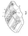
- a fixed caliper brake 1 for a motor vehicle is releasably attachable to a steering knuckle of a motor vehicle, and comprises an integrally formed housing 2 (monoblock housing) with two substantially laterally placed, at least one wheel side substantially completely closed, plateau-shaped housing legs 3.4 and with a Housing bridge 5, the housing legs 3, 4 rigidly connected to each other at a defined distance a.
- a closed, planar, contour of the housing legs 3.4 conveys a special, aesthetically closed and harmonious appearance, which is particularly suitable for applying design elements such as manufacturer particular emblems public appeal.
- the substantially completely closed housing formed bridge 5 ensures high bending stiffness and harmonizes with a closed overall appearance of the housing legs 3.4.
- Each brake pad 6.7 is directly actuated by at least one of the pistons 13,14.
- the back plate 11 has - substantially opposite and each starting from the central portion 12 laterally in the circumferential direction facing - legs 15,16, each of Leg portions 42, 43 are made, which serve for pulling support of the circumferential forces on the housing 2.
- each back plate 11 on the inlet side and positively in a radially outer region on a plan machined, defined contact surface 17,18 of the housing bridge 5 is supported, which as a counter body for introducing force acts. Furthermore, it is defined that each back plate 11 of a brake lining 6, 7 has on the inlet side at least one hook-shaped radially outwardly pointing leg 15, 16 which extends with the leg section 42 first in the circumferential direction u, and then with the leg section 43 radially outward parallel to the contact surface 17,18 is directed by the housing bridge 5, to receive a portion of the housing bridge 5 radially outward radially.
- Each leg 15,16 may be formed in particular hammerhead-shaped, with a hammerhead tip points radially outward.
- an ideal point of application X of the introduction of force into the housing 2 is aligned with a centroid Y of the friction mass 10 such that the brake lining 6. 7 has basically no tendency to rotate, because no force pair is formed, and consequently no parasitic rotational effect is produced.
- At least one housing fixedly arranged spring element 21 which acts permanently elastically on the two brake pads 6.7 with at least one spring arm 22,23 so that they can be pressed radially outward to rest in the recording in the housing 2. Details and alternatives are explained later in the text.
- the fixed caliper brake 1 described above is predestined especially for light passenger cars, for additionally recuperatively braked motor vehicles, or for use in the region of a rear axle, because these applications primarily require relatively low braking torques, circumferential forces or limited energetic conversion, or if for other reasons a purely one-sided ( inlet side) force support of circumferential forces may be sufficient.
- An alternative fixed caliper brake 1 allows increased energy conversion and increased braking torques, or reduced surface pressure at points of attack by the power flow is split, so that additional attack points X1, X2 can be used.
- forces are not only at an inlet end - in a sense, exclusively on Traction claimed back plate 11 - initiated, but it is for particularly high braking moments in addition a somewhat depressed (push) support the back plate 11 allows.
- each back plate 11 may be formed quasi-elastic, and at the respective outlet side leg an additional contact surface 24,25 have such that at least for high stresses an additional point X2 for initiating frictional forces (circumferential forces) on a frame-like extension 26,27 of the housing bridge 5 is provided.
- the power flow is effectively split, wherein a first force component at the point of application X1 can be introduced on the inlet side of a stop surface 29, and wherein an additional force component, especially at high circumferential forces, can be introduced at the outgoing point x2 in a stop surface 30.
- the support can be arranged differently in different ways (pull-support and additionally push-support starting with small peripheral forces or pulling forces). Support at low circumferential forces and additional push support from increased circumferential forces).
- a cost-effective processing of radially extending abutment surfaces 29,30,31,32 from the housing 2 provides that a single tool (cutter or broaching profile) is designed and dimensioned such, and wherein the tool is guided by the extension 26, 27 of the housing 2 in that two opposing abutment surfaces 29, 31; 30, 32 can be machined simultaneously with a tool feed movement.
- a particularly favorable design is given when the housing 2 from the fixed caliper of lightweight material in one piece urgeformt - that is poured - is formed in a sand casting or in a Kokillenguss vide, and wherein the bore 8.9 are introduced by suitable measures in the housing legs 3.4 machined in that a tool is inserted between the housing legs 3, 4 into the intermediate space which, after complete assembly of the fixed caliper, receives the brake pads 6, 7 and the brake disk.
- Another mandatory measure in the fixed caliper brakes 1 is to provide at least one hydraulic connection 36 between opposing hydraulic pressure chambers 35 in the opposite housing legs.
- This hydraulic connection 36 can internally, so starting from a pressure chamber 35 in a housing leg 3.4, or starting from a connecting hole 33 between pressure chambers 35 in this housing leg 3.4, through the housing bridge 5 through to a hydraulic pressure chamber 33 a in the opposite arranged housing legs 3,4, or to a connecting hole 33a between pressure chambers 33a, 33b in this housing leg, be guided, so that the hydraulic wiring is provided completely integrated.
- connection holes segmented from several bore sections and wherein the bore sections are aligned at an angle to each other.
- the closure means are formed as balls whose diameter is dimensioned slightly larger than the bore diameter, so that by the pressing of the balls a hydraulically sealed closure of the tool inlet openings and tool outlet openings is generated.
- closure means in particular balls, alternatively or additionally to the press-fit with the housing material, wherein, for example, a plurality of circumferentially regularly distributed force introduction points are provided, which are visually apparent by press marks on the product.
- an externally mounted, conventional pipe connection between the housing legs 3, 4 can be provided, which enables a reduced amount of machining effort.
- Mixed forms are conceivable, for example, by the pressure chambers 35 are connected in a housing leg 3.4 by internal connection holes, and wherein the two housing legs 3.4 are supplied by a mounted pipe connection.
- the electromechanical wheel brakes in principle comprise a completely different active energy
- the electrical energy supply by means of electrical wiring is basically analogous to the hydraulic active power supply - as described above.
- a brake pad engages 6,7 of radially inwardly of the housing bridge of the fixed caliper brake 1, so that there is a corresponding leadership and captive in the direction radially outward.
- In the direction of radially inward usually prevents a constructively given brake disk hub (wheel hub) falling out of the brake pads 6.7, so that thereby a constructive, form-fitting effective, and fail-safe captive is given.
- a change of the brake pads 6,7 is made by the caliper is removed from the steering knuckle, and wherein the brake pads 6,7 are removed from the housing 2 after the spring element 21 is removed.
- the feathering is in each case designed so that the brake linings 6, 7 are permanently pulled or pressed radially outward into the guide.
- the at least one resiliently biased spring element 21 is provided between pistons 13, 14 and / or housing 2 and brake linings 6, 7, and urges at least one or both brake linings 6, 7 radially outward in the direction of the housing bridge 5.
- the back plate 11 has at least one spring leg 39 for engagement in a cup-shaped piston 13,14, and wherein the spring action is directed radially outwardly.
- a spring element 21 on the housing 2 radially inwardly, arranged in the region of a brake disk hub, and presses the brake pads 6.7 radially outward in their leadership.
- the spring element 21 may in particular be provided detachably fastened. For example, a screw from the spring element 21 on the housing 2.
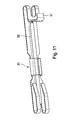
- a spring element 21 may be produced from steel wire or from a flat sheet steel formed substantially without cutting and have a corresponding sheet metal design with axially directed, rib-shaped reinforcement 52.
- a screw or locking arrangement on the housing 2 wherein by way of example at least one locking portion 37 slides from the spring element 21 on an associated guide 39, and thereby automatically with an axially directed insertion form fit in or behind at least one recess or undercut 38 can engage from the housing 2, so that an axially directed mounting of the spring element 21 is made possible.
- the assembly takes place by the brake pads 6.7 are inserted into the housing 2, and then the spring element 21 is inserted parallel to the axial direction ax through an opening 40 of the back plate 11 before the assembly of the housing 2 takes place on the motor vehicle.
- the housing 2 has at least one recess, preferably an integrated mounting, snap or latching attachment for a positive reception of a locking portion 37 of the spring element 21. Subsequent to an integrated guide 39, the locking section 37 snaps into the undercut 38 of the housing 2 in an elastically form-fitting manner after reversible-elastic deformation. As a result, the spring element 21 is fixedly arranged on the housing 2.
- the spring element 21 can in particular by a component after Fig. 17 take on additional tasks along with the following characteristics.
- the spring element 21 is formed as a carrier for attachment of a holding element 46, it may additionally serve to carry at least one other component.
- the holding element 46 may have legs 50, 51 which fix one or more conductors 47, 48 of brake pad wear warning devices BBW (warning contacts) elastically to the housing 2 such that these conductors 47, 48 are in the area of a visible front or bridge surface, for example from the housing 2 visually appealing and inexpensive led to the housing 2, and are arranged secured against abrasion, damage, etc.
- BBW brake pad wear warning devices
- the bar-shaped, parallel to the axial direction ax extending spring element 21 has a multiple function.
- the invention is also particularly advantageous for solutions in which at least one separate warning contact for monitoring the state of wear of a friction mass 10 is placed on each wheel brake, in each case on both sides of a brake disk.
- at least one elastic latching device 49 may be provided, which advantageously has a plurality of arms which serve for releasable attachment of the retaining element 46.
- the attachment is achieved so that the holding element 46 engages in a recess of the spring element 21.
- the brake pads 6,7 can after the Figures 3 . 4 . 5 . 13 . 14 combinatorial with all the features mentioned, or in each case be provided with the following features.
- At least one of the leg portions 42,43 of the back plate 11 may have a thickness t1 which is formed larger than a thickness t2 of the central portion 12 of the back plate 11. Because the placement of the thickening t1 a tensile stress cross-section substantially over the entire height H. Increased in the region of the prevailing tensile stresses, an improved, notch effect reduced tensile stress introduction into the leg sections 42,43 is possible.
- an additional volume of material for the creation of To supply thickening in the free voltage cross section of the leg sections 42,43 is provided.
- the system thus differs sufficiently from the basic idea of a known, hammerhead-shaped backplate for a floating caliper, which is designed to be substantially thickened only in the region of a bearing surface EP 1 217 247 B1 , Wherein the free end is substantially thickened in the region of a support of the counter body (holder) to form primarily an enlarged bearing surface for the counter body, so that surface pressure in the region of this edition is reduced.
- housing 2 of the fixed caliper brake 1 is in principle that an attachment between not shown Achsschenkel and housing 2 with mutual adaptation of the interface by means of radially directed fasteners (screws) or by means of axially directed fasteners (screws) or a hybrid form of these Variants can be made, and wherein the fastening means are guided by appropriately aligned mounting holes on the housing 2.
Landscapes
- Engineering & Computer Science (AREA)
- General Engineering & Computer Science (AREA)
- Mechanical Engineering (AREA)
- Transportation (AREA)
- Braking Arrangements (AREA)
Applications Claiming Priority (4)
| Application Number | Priority Date | Filing Date | Title |
|---|---|---|---|
| DE102010029679 | 2010-06-02 | ||
| DE102010043898A DE102010043898A1 (de) | 2010-06-02 | 2010-11-15 | Festsattelbremse und Bremsbelag für eine Festsattelbremse |
| EP11721326.4A EP2577085B1 (fr) | 2010-06-02 | 2011-05-25 | Frein à étrier fixe et garniture de frein pour un frein à étrier fixe |
| PCT/EP2011/058543 WO2011151235A1 (fr) | 2010-06-02 | 2011-05-25 | Frein à étrier fixe et garniture de frein pour un frein à étrier fixe |
Related Parent Applications (2)
| Application Number | Title | Priority Date | Filing Date |
|---|---|---|---|
| EP11721326.4A Division EP2577085B1 (fr) | 2010-06-02 | 2011-05-25 | Frein à étrier fixe et garniture de frein pour un frein à étrier fixe |
| EP11721326.4A Division-Into EP2577085B1 (fr) | 2010-06-02 | 2011-05-25 | Frein à étrier fixe et garniture de frein pour un frein à étrier fixe |
Publications (2)
| Publication Number | Publication Date |
|---|---|
| EP3104035A1 true EP3104035A1 (fr) | 2016-12-14 |
| EP3104035B1 EP3104035B1 (fr) | 2019-08-28 |
Family
ID=44973953
Family Applications (2)
| Application Number | Title | Priority Date | Filing Date |
|---|---|---|---|
| EP16173649.1A Active EP3104035B1 (fr) | 2010-06-02 | 2011-05-25 | Garniture de frein pour freins a etrier |
| EP11721326.4A Active EP2577085B1 (fr) | 2010-06-02 | 2011-05-25 | Frein à étrier fixe et garniture de frein pour un frein à étrier fixe |
Family Applications After (1)
| Application Number | Title | Priority Date | Filing Date |
|---|---|---|---|
| EP11721326.4A Active EP2577085B1 (fr) | 2010-06-02 | 2011-05-25 | Frein à étrier fixe et garniture de frein pour un frein à étrier fixe |
Country Status (10)
| Country | Link |
|---|---|
| US (1) | US9365193B2 (fr) |
| EP (2) | EP3104035B1 (fr) |
| JP (1) | JP6000943B2 (fr) |
| CN (1) | CN102918293B (fr) |
| BR (1) | BR112012030692B1 (fr) |
| DE (1) | DE102010043898A1 (fr) |
| DK (1) | DK2577085T3 (fr) |
| ES (1) | ES2623026T3 (fr) |
| PL (1) | PL2577085T3 (fr) |
| WO (1) | WO2011151235A1 (fr) |
Families Citing this family (29)
| Publication number | Priority date | Publication date | Assignee | Title |
|---|---|---|---|---|
| DE102012008572B4 (de) | 2012-04-27 | 2017-03-16 | Knorr-Bremse Systeme für Nutzfahrzeuge GmbH | Befestigung eines Kontaktleiters einer Vorrichtung zur Überwachung eines Bremsbelagverschleißes |
| DE102012012832A1 (de) * | 2012-06-28 | 2014-01-02 | Knorr-Bremse Systeme für Nutzfahrzeuge GmbH | Scheibenbremse für ein Nutzfahrzeug sowie Bremsbelag für eine Scheibenbremse |
| USD712809S1 (en) * | 2013-02-15 | 2014-09-09 | Wabco Gmbh | Disk brake friction lining retaining device |
| DE202013101406U1 (de) | 2013-04-02 | 2013-05-06 | Haldex Brake Products Ab | Scheibenbremse |
| CN106460975B (zh) | 2014-04-08 | 2019-06-18 | 福乐尼·乐姆宝公开有限公司 | 盘式制动衬块、用于盘式制动卡钳的弹簧以及盘式制动卡钳总成 |
| DE102014111228B4 (de) * | 2014-08-07 | 2016-11-10 | Knorr-Bremse Systeme für Nutzfahrzeuge GmbH | Scheibenbremse für ein Nutzfahrzeug |
| CN104948618B (zh) * | 2015-06-30 | 2017-11-17 | 吉林大学 | 一种定钳盘式电子驻车制动器及汽车 |
| DE102015111847A1 (de) * | 2015-07-22 | 2017-01-26 | Knorr-Bremse Systeme für Nutzfahrzeuge GmbH | Montagewerkzeug für Belaghaltebügel mit Sicherungsvorrichtung einer Scheibenbremse, Scheibenbremse und Bremsbelagsatz |
| DE102016209069A1 (de) | 2015-08-31 | 2017-03-02 | Continental Teves Ag & Co. Ohg | Rückenplatte für einen Scheibenbremsbelag, Scheibenbremsbelag und Festsattelscheibenbremse dazu |
| DE102015118838B4 (de) * | 2015-11-03 | 2024-10-10 | Knorr-Bremse Systeme für Nutzfahrzeuge GmbH | Scheibenbremse mit Belaghaltebügel und Sicherungsvorrichtung, und Bremsbelagsatz |
| FR3046444B1 (fr) | 2015-12-31 | 2018-01-05 | Chassis Brakes International B.V. | Guide de glissement de garniture de freinage pour frein a disque, procedes de fabrication et d'assemblage associes |
| FR3046443A1 (fr) | 2016-01-01 | 2017-07-07 | Foundation Brakes France | Guide de glissement de patin de garniture pour reduction du freinage residuel |
| DE102016204240A1 (de) | 2016-01-11 | 2017-07-13 | Continental Teves Ag & Co. Ohg | Kraftfahrzeugscheibenbremsbelag mit rückenplattenseitiger Erhebung sowie Dämpfungsplatte zur Applikation an einem entsprechenden Kraftfahrzeugscheibenbremsbelag einschließlich deren Verwendung in einer Kraftfahrzeugscheibenbremse |
| DE202017000093U1 (de) | 2016-01-11 | 2017-02-15 | Continental Teves Ag & Co. Ohg | Kraftfahrzeugscheibenbremsbelag mit rückenplattenseitiger Erhebung sowie Dämpfungsplatte zur Applikation an einem entsprechenden Kraftfahrzeugscheibenbremsbelag einschließlich deren Verwendung in einer Kraftfahrzeugscheibenbremse |
| DE102016100623A1 (de) * | 2016-01-15 | 2017-07-20 | Bpw Bergische Achsen Kg | Bremsbelaghalterung einer Fahrzeug-Scheibenbremse sowie Niederhalter für die Befestigung von Bremsbelägen |
| DE102016202520A1 (de) * | 2016-02-18 | 2017-08-24 | Continental Teves Ag & Co. Ohg | Reibbelaganordnung mit Rückstellfeder zur Lüftspiellimitierung für eine Kraftfahrzeugteilbelagscheibenbremse |
| CN109073013B (zh) * | 2016-04-04 | 2020-07-14 | 克诺尔商用车制动系统有限公司 | 用于紧固信号线缆的紧固装置 |
| IT201600130800A1 (it) * | 2016-12-23 | 2018-06-23 | Freni Brembo Spa | Dispositivo a molla per freno a disco, assieme di pastiglia e molla e pinza freno |
| DE102017108175A1 (de) * | 2017-04-18 | 2018-10-18 | Bpw Bergische Achsen Kg | Scheibenbremse und Niederhalter zur Befestigung von Bremspads |
| SE543502C2 (en) * | 2017-06-13 | 2021-03-09 | Varel Int Ind L L C | Superabrasive cutters for earth boring bits with multiple raised cutting surfaces and a drill bit comprising such cutters |
| CN107237845A (zh) * | 2017-08-15 | 2017-10-10 | 张建平 | 一种汽车刹车卡钳罩连接与紧固方法 |
| EP3499072A1 (fr) * | 2017-12-15 | 2019-06-19 | Meritor Heavy Vehicle Braking Systems (UK) Limited | Étrier de frein |
| CN112277899A (zh) * | 2020-10-09 | 2021-01-29 | 东莞市威尼汽车制动用品有限公司 | 一种电子手刹车型后轮改装结构 |
| CN112537282B (zh) * | 2020-12-18 | 2021-10-29 | 南京信息职业技术学院 | 用于无人驾驶汽车的紧急刹车装置 |
| CN117677781B (zh) * | 2021-07-28 | 2024-07-16 | 日本轻金属株式会社 | 活塞收容体 |
| CN216045120U (zh) * | 2021-11-02 | 2022-03-15 | 蔚来汽车科技(安徽)有限公司 | 用于车辆的制动器及车辆 |
| CN114537362B (zh) * | 2022-04-27 | 2022-07-19 | 宁波合力制动系统有限公司 | 一种挂车刹车片制动器衬片磨损监测报警装置 |
| GB2627969B (en) * | 2023-03-09 | 2025-04-09 | Mei Brakes Ltd | Air disc brake pad |
| DE102023118402A1 (de) * | 2023-07-12 | 2025-01-16 | Zf Cv Systems Europe Bv | Scheibenbremse für ein Kraftfahrzeug, sowie Kraftfahrzeuge mit einer Scheibenbremse |
Citations (7)
| Publication number | Priority date | Publication date | Assignee | Title |
|---|---|---|---|---|
| WO1992017713A1 (fr) * | 1991-04-04 | 1992-10-15 | Alfred Teves Gmbh | Frein a disque a garniture partielle et a etrier fixe |
| DE4133486A1 (de) * | 1991-04-04 | 1993-04-15 | Teves Gmbh Alfred | Festsattel-teilbelagscheibenbremse |
| US5297659A (en) * | 1990-08-31 | 1994-03-29 | Alfred Teves Gmbh | Floating caliper and brake shoe for spot-type disc brakes |
| WO1994024454A1 (fr) * | 1993-04-15 | 1994-10-27 | Alliedsignal Europe Services Techniques | Frein a disque utilisant un patin tire a appui permanent |
| EP0602866B1 (fr) | 1992-12-15 | 1997-03-05 | Lucas Industries Public Limited Company | Assemblage d'un indicateur d'usure d'une garniture de frein |
| DE102006052178A1 (de) * | 2005-11-17 | 2007-06-06 | Continental Teves Ag & Co. Ohg | Bremsbelag für eine Teilbelag-Scheibenbremse |
| EP1217247B1 (fr) | 2000-12-22 | 2007-10-03 | Continental Teves AG & Co. oHG | Patin de frein pour frein à disque à garnitures partielles |
Family Cites Families (30)
| Publication number | Priority date | Publication date | Assignee | Title |
|---|---|---|---|---|
| US3189129A (en) | 1962-10-04 | 1965-06-15 | Bendix Corp | Brake shoe retainer |
| JPS5844534U (ja) * | 1981-09-18 | 1983-03-25 | トキコ株式会社 | デイスクブレ−キ |
| DE8502975U1 (de) * | 1985-02-04 | 1986-05-28 | Lucas Industries P.L.C., Birmingham, West Midlands | Verschleißanzeigevorrichtung für Bremsbeläge |
| IT1222967B (it) | 1987-10-22 | 1990-09-12 | Brembo Spa | Complesso di freno a disco per autoveicoli e simili |
| FR2622260B1 (fr) | 1987-10-23 | 1990-03-30 | Peugeot | Dispositif de commande par cable destine a etre monte sur une cloison telle que par exemple un tablier de vehicule |
| GB2231928B (en) * | 1989-05-26 | 1993-02-17 | Teves Gmbh Alfred | Spot-type disc brake |
| DE4110850A1 (de) * | 1991-04-04 | 1992-10-08 | Teves Gmbh Alfred | Schwimmsattel-teilbelagscheibenbremse mit aktiv zurueckstellenden bremsbacken |
| DE4136107A1 (de) * | 1991-11-02 | 1993-05-06 | Alfred Teves Gmbh, 6000 Frankfurt, De | Bremsklotz mit verdrehgesicherter haltefeder |
| US5538105A (en) | 1995-03-07 | 1996-07-23 | Dayton Walther Corporation | Brake shoe hold down clip for disc brake assembly |
| DE29824937U1 (de) | 1997-06-03 | 2003-06-26 | Meritor Heavy Vehicle Systems, LLC, Troy, Mich. | Verbesserungen an Bremsschuh- und -belagbaugruppen für Scheibenbremsen |
| WO2000049307A1 (fr) * | 1999-02-18 | 2000-08-24 | Continental Teves Ag & Co. Ohg | Plaquette de frein dotee d'un dispositif ressort de retenue |
| DE60108669T2 (de) | 2000-10-27 | 2006-01-05 | Société de Technologie Michelin | Reifenaufbautrommel |
| DE10218907A1 (de) | 2002-04-26 | 2003-12-04 | Tmd Friction Europe Gmbh | Fahrwerk-Baugruppe für Kraftfahrzeuge |
| AU2002334386A1 (en) | 2002-07-22 | 2004-02-09 | Freni Brembo S.P.A. | Pad for caliper of disc brake |
| JP2004239356A (ja) * | 2003-02-06 | 2004-08-26 | Honda Motor Co Ltd | 二輪車用ディスクブレーキ装置 |
| WO2005036010A1 (fr) | 2003-10-14 | 2005-04-21 | Continental Teves Ag & Co. Ohg | Frein a disque a garniture partielle dote d'un ensemble ressort |
| EP1700050B1 (fr) | 2003-12-30 | 2009-07-22 | Freni Brembo S.p.A. | Ressort de patin ou organe elastique pour frein a disque |
| JP2006057718A (ja) * | 2004-08-19 | 2006-03-02 | Akebono Brake Ind Co Ltd | フローティングキャリパ型ディスクブレーキ |
| DE102005046804A1 (de) * | 2005-01-18 | 2006-08-17 | Continental Teves Ag & Co. Ohg | Teilbelag-Scheibenbremse |
| JP2006322571A (ja) | 2005-05-20 | 2006-11-30 | Akebono Brake Ind Co Ltd | フローティングキャリパ型ディスクブレーキ |
| US20060283673A1 (en) * | 2005-06-15 | 2006-12-21 | Lamport Robert A | Brake assembly and additive |
| US7331430B2 (en) * | 2006-01-05 | 2008-02-19 | Delphi Technologies, Inc. | Multi-disc brake with fixed center brake pad assembly |
| ATE437313T1 (de) | 2006-02-17 | 2009-08-15 | Freni Brembo Spa | Federn zum halten von backen in einem scheibenbremssattel |
| DE102007006472A1 (de) * | 2006-04-20 | 2007-11-08 | Continental Teves Ag & Co. Ohg | Scheibenbremse |
| JP4668844B2 (ja) | 2006-05-29 | 2011-04-13 | 曙ブレーキ工業株式会社 | 対向ピストン型ディスクブレーキ |
| JP2008164070A (ja) * | 2006-12-28 | 2008-07-17 | Advics:Kk | ピストン対向型ディスクブレーキ装置 |
| DE102008013268A1 (de) | 2007-10-09 | 2009-04-16 | Continental Engineering Services Gmbh | Bremsbelag für eine Teilbelag-Scheibenbremse |
| DE202008013446U1 (de) | 2008-10-09 | 2009-04-09 | Haldex Brake Products Ab | Scheibenbremse sowie Haltebügel und Sperrvorrichtung für Belaghaltefedern hierfür |
| JP5157816B2 (ja) * | 2008-10-21 | 2013-03-06 | 株式会社アドヴィックス | ピストン対向型ディスクブレーキ |
| JP4741692B2 (ja) | 2009-06-23 | 2011-08-03 | 本田技研工業株式会社 | 対向ピストン型キャリパボディ |
-
2010
- 2010-11-15 DE DE102010043898A patent/DE102010043898A1/de active Pending
-
2011
- 2011-05-25 ES ES11721326.4T patent/ES2623026T3/es active Active
- 2011-05-25 EP EP16173649.1A patent/EP3104035B1/fr active Active
- 2011-05-25 CN CN201180026939.XA patent/CN102918293B/zh active Active
- 2011-05-25 JP JP2013512834A patent/JP6000943B2/ja active Active
- 2011-05-25 BR BR112012030692-8A patent/BR112012030692B1/pt not_active IP Right Cessation
- 2011-05-25 EP EP11721326.4A patent/EP2577085B1/fr active Active
- 2011-05-25 PL PL11721326T patent/PL2577085T3/pl unknown
- 2011-05-25 US US13/700,481 patent/US9365193B2/en not_active Expired - Fee Related
- 2011-05-25 WO PCT/EP2011/058543 patent/WO2011151235A1/fr not_active Ceased
- 2011-05-25 DK DK11721326.4T patent/DK2577085T3/en active
Patent Citations (7)
| Publication number | Priority date | Publication date | Assignee | Title |
|---|---|---|---|---|
| US5297659A (en) * | 1990-08-31 | 1994-03-29 | Alfred Teves Gmbh | Floating caliper and brake shoe for spot-type disc brakes |
| WO1992017713A1 (fr) * | 1991-04-04 | 1992-10-15 | Alfred Teves Gmbh | Frein a disque a garniture partielle et a etrier fixe |
| DE4133486A1 (de) * | 1991-04-04 | 1993-04-15 | Teves Gmbh Alfred | Festsattel-teilbelagscheibenbremse |
| EP0602866B1 (fr) | 1992-12-15 | 1997-03-05 | Lucas Industries Public Limited Company | Assemblage d'un indicateur d'usure d'une garniture de frein |
| WO1994024454A1 (fr) * | 1993-04-15 | 1994-10-27 | Alliedsignal Europe Services Techniques | Frein a disque utilisant un patin tire a appui permanent |
| EP1217247B1 (fr) | 2000-12-22 | 2007-10-03 | Continental Teves AG & Co. oHG | Patin de frein pour frein à disque à garnitures partielles |
| DE102006052178A1 (de) * | 2005-11-17 | 2007-06-06 | Continental Teves Ag & Co. Ohg | Bremsbelag für eine Teilbelag-Scheibenbremse |
Also Published As
| Publication number | Publication date |
|---|---|
| EP2577085A1 (fr) | 2013-04-10 |
| CN102918293B (zh) | 2015-07-08 |
| BR112012030692B1 (pt) | 2021-07-13 |
| BR112012030692A2 (pt) | 2020-09-01 |
| CN102918293A (zh) | 2013-02-06 |
| ES2623026T3 (es) | 2017-07-10 |
| US9365193B2 (en) | 2016-06-14 |
| JP2013531195A (ja) | 2013-08-01 |
| JP6000943B2 (ja) | 2016-10-05 |
| EP3104035B1 (fr) | 2019-08-28 |
| EP2577085B1 (fr) | 2017-01-25 |
| US20130068573A1 (en) | 2013-03-21 |
| DE102010043898A1 (de) | 2011-12-08 |
| PL2577085T3 (pl) | 2017-06-30 |
| DK2577085T3 (en) | 2017-04-10 |
| WO2011151235A1 (fr) | 2011-12-08 |
Similar Documents
| Publication | Publication Date | Title |
|---|---|---|
| EP3104035B1 (fr) | Garniture de frein pour freins a etrier | |
| EP3359842B1 (fr) | Frein à disque pour véhicule utilitaire | |
| EP3344892B1 (fr) | Plaque dorsale pour une garniture de frein à disque, garniture de frein à disque et frein à disque à étrier fixe | |
| EP2411694B1 (fr) | Frein à disque à garnitures partielles présentant un agencement de ressort permettant d'améliorer le jeu, ainsi qu'agencement de ressort | |
| WO2012104395A2 (fr) | Module de tambour de frein fonctionnant à l'aide d'un moteur électrique | |
| EP2753843B1 (fr) | Piston pour un étrier de frein à disque | |
| DE19954585C2 (de) | Verfahren zum Herstellen eines Reibringes, insbesondere für eine Bremsscheibe und Bremsscheibe | |
| DE102016202520A1 (de) | Reibbelaganordnung mit Rückstellfeder zur Lüftspiellimitierung für eine Kraftfahrzeugteilbelagscheibenbremse | |
| EP3791085B1 (fr) | Plâte de support de semelle de frein à disque confectionée en dépendance de la direction de rotation | |
| EP1771670B1 (fr) | Rotor pouvant etre raccorde a un moyeu de roue d'un vehicule automobile | |
| DE102014112665A1 (de) | Bremsbelaghalterung einer Scheibenbremse, Scheibenbremse und Bremsbelag | |
| DE102014017715A1 (de) | Pneumatisch oder elektromechanisch betätigte Scheibenbremse für Nutzfahrzeuge | |
| DE102013210528A1 (de) | Elektrisch betätigbare Trommelbremse | |
| WO2017036763A1 (fr) | Frein à disque d'un véhicule utilitaire | |
| EP3414466B1 (fr) | Frein à disque à garnitures partielles de véhicule automobile comprenant des garnitures de friction supportées en traction à l'aide d'un support en forme de cadre | |
| DE102014113369A1 (de) | Anordnung eines Bremsträgers einer Scheibenbremse an einer Fahrzeugachse, Bremsträger und Scheibenbremse | |
| EP2507530A1 (fr) | Module de roue | |
| DE102008031709A1 (de) | Scheibenbremsanordnung für ein Fahrzeug, insbesondere für ein Nutzfahrzeug | |
| DE102005059247A1 (de) | Bremsvorrichtung | |
| DE102014002324A1 (de) | Bremsscheibe, Kraftfahrzeug | |
| DE10328679B3 (de) | Radträgereinheit mit integrierter Zuspanneinheit | |
| EP1893881B1 (fr) | Dispositif de freinage | |
| DE102019129950A1 (de) | Zweiteiliger Planetenträger mit geteilter Funktionalität | |
| EP1840403A2 (fr) | Disque de frein pour motocyclette | |
| DE102012012844C5 (de) | Scheibenbremse für ein Nutzfahrzeug sowie Bremsbelag für eine Scheibenbremse |
Legal Events
| Date | Code | Title | Description |
|---|---|---|---|
| PUAI | Public reference made under article 153(3) epc to a published international application that has entered the european phase |
Free format text: ORIGINAL CODE: 0009012 |
|
| STAA | Information on the status of an ep patent application or granted ep patent |
Free format text: STATUS: THE APPLICATION HAS BEEN PUBLISHED |
|
| AC | Divisional application: reference to earlier application |
Ref document number: 2577085 Country of ref document: EP Kind code of ref document: P |
|
| AK | Designated contracting states |
Kind code of ref document: A1 Designated state(s): AL AT BE BG CH CY CZ DE DK EE ES FI FR GB GR HR HU IE IS IT LI LT LU LV MC MK MT NL NO PL PT RO RS SE SI SK SM TR |
|
| STAA | Information on the status of an ep patent application or granted ep patent |
Free format text: STATUS: REQUEST FOR EXAMINATION WAS MADE |
|
| 17P | Request for examination filed |
Effective date: 20170614 |
|
| RBV | Designated contracting states (corrected) |
Designated state(s): AL AT BE BG CH CY CZ DE DK EE ES FI FR GB GR HR HU IE IS IT LI LT LU LV MC MK MT NL NO PL PT RO RS SE SI SK SM TR |
|
| STAA | Information on the status of an ep patent application or granted ep patent |
Free format text: STATUS: EXAMINATION IS IN PROGRESS |
|
| 17Q | First examination report despatched |
Effective date: 20180614 |
|
| RAP1 | Party data changed (applicant data changed or rights of an application transferred) |
Owner name: CONTINENTAL TEVES AG & CO. OHG |
|
| GRAP | Despatch of communication of intention to grant a patent |
Free format text: ORIGINAL CODE: EPIDOSNIGR1 |
|
| STAA | Information on the status of an ep patent application or granted ep patent |
Free format text: STATUS: GRANT OF PATENT IS INTENDED |
|
| INTG | Intention to grant announced |
Effective date: 20190405 |
|
| GRAS | Grant fee paid |
Free format text: ORIGINAL CODE: EPIDOSNIGR3 |
|
| GRAA | (expected) grant |
Free format text: ORIGINAL CODE: 0009210 |
|
| STAA | Information on the status of an ep patent application or granted ep patent |
Free format text: STATUS: THE PATENT HAS BEEN GRANTED |
|
| AC | Divisional application: reference to earlier application |
Ref document number: 2577085 Country of ref document: EP Kind code of ref document: P |
|
| AK | Designated contracting states |
Kind code of ref document: B1 Designated state(s): AL AT BE BG CH CY CZ DE DK EE ES FI FR GB GR HR HU IE IS IT LI LT LU LV MC MK MT NL NO PL PT RO RS SE SI SK SM TR |
|
| REG | Reference to a national code |
Ref country code: GB Ref legal event code: FG4D Free format text: NOT ENGLISH |
|
| REG | Reference to a national code |
Ref country code: CH Ref legal event code: EP |
|
| REG | Reference to a national code |
Ref country code: AT Ref legal event code: REF Ref document number: 1172784 Country of ref document: AT Kind code of ref document: T Effective date: 20190915 |
|
| REG | Reference to a national code |
Ref country code: IE Ref legal event code: FG4D Free format text: LANGUAGE OF EP DOCUMENT: GERMAN |
|
| REG | Reference to a national code |
Ref country code: DE Ref legal event code: R096 Ref document number: 502011016055 Country of ref document: DE |
|
| REG | Reference to a national code |
Ref country code: RO Ref legal event code: EPE |
|
| REG | Reference to a national code |
Ref country code: NL Ref legal event code: MP Effective date: 20190828 |
|
| REG | Reference to a national code |
Ref country code: LT Ref legal event code: MG4D |
|
| PG25 | Lapsed in a contracting state [announced via postgrant information from national office to epo] |
Ref country code: HR Free format text: LAPSE BECAUSE OF FAILURE TO SUBMIT A TRANSLATION OF THE DESCRIPTION OR TO PAY THE FEE WITHIN THE PRESCRIBED TIME-LIMIT Effective date: 20190828 Ref country code: LT Free format text: LAPSE BECAUSE OF FAILURE TO SUBMIT A TRANSLATION OF THE DESCRIPTION OR TO PAY THE FEE WITHIN THE PRESCRIBED TIME-LIMIT Effective date: 20190828 Ref country code: PT Free format text: LAPSE BECAUSE OF FAILURE TO SUBMIT A TRANSLATION OF THE DESCRIPTION OR TO PAY THE FEE WITHIN THE PRESCRIBED TIME-LIMIT Effective date: 20191230 Ref country code: NL Free format text: LAPSE BECAUSE OF FAILURE TO SUBMIT A TRANSLATION OF THE DESCRIPTION OR TO PAY THE FEE WITHIN THE PRESCRIBED TIME-LIMIT Effective date: 20190828 Ref country code: BG Free format text: LAPSE BECAUSE OF FAILURE TO SUBMIT A TRANSLATION OF THE DESCRIPTION OR TO PAY THE FEE WITHIN THE PRESCRIBED TIME-LIMIT Effective date: 20191128 Ref country code: NO Free format text: LAPSE BECAUSE OF FAILURE TO SUBMIT A TRANSLATION OF THE DESCRIPTION OR TO PAY THE FEE WITHIN THE PRESCRIBED TIME-LIMIT Effective date: 20191128 Ref country code: FI Free format text: LAPSE BECAUSE OF FAILURE TO SUBMIT A TRANSLATION OF THE DESCRIPTION OR TO PAY THE FEE WITHIN THE PRESCRIBED TIME-LIMIT Effective date: 20190828 Ref country code: SE Free format text: LAPSE BECAUSE OF FAILURE TO SUBMIT A TRANSLATION OF THE DESCRIPTION OR TO PAY THE FEE WITHIN THE PRESCRIBED TIME-LIMIT Effective date: 20190828 |
|
| PG25 | Lapsed in a contracting state [announced via postgrant information from national office to epo] |
Ref country code: RS Free format text: LAPSE BECAUSE OF FAILURE TO SUBMIT A TRANSLATION OF THE DESCRIPTION OR TO PAY THE FEE WITHIN THE PRESCRIBED TIME-LIMIT Effective date: 20190828 Ref country code: GR Free format text: LAPSE BECAUSE OF FAILURE TO SUBMIT A TRANSLATION OF THE DESCRIPTION OR TO PAY THE FEE WITHIN THE PRESCRIBED TIME-LIMIT Effective date: 20191129 Ref country code: IS Free format text: LAPSE BECAUSE OF FAILURE TO SUBMIT A TRANSLATION OF THE DESCRIPTION OR TO PAY THE FEE WITHIN THE PRESCRIBED TIME-LIMIT Effective date: 20191228 Ref country code: AL Free format text: LAPSE BECAUSE OF FAILURE TO SUBMIT A TRANSLATION OF THE DESCRIPTION OR TO PAY THE FEE WITHIN THE PRESCRIBED TIME-LIMIT Effective date: 20190828 Ref country code: ES Free format text: LAPSE BECAUSE OF FAILURE TO SUBMIT A TRANSLATION OF THE DESCRIPTION OR TO PAY THE FEE WITHIN THE PRESCRIBED TIME-LIMIT Effective date: 20190828 Ref country code: LV Free format text: LAPSE BECAUSE OF FAILURE TO SUBMIT A TRANSLATION OF THE DESCRIPTION OR TO PAY THE FEE WITHIN THE PRESCRIBED TIME-LIMIT Effective date: 20190828 |
|
| PG25 | Lapsed in a contracting state [announced via postgrant information from national office to epo] |
Ref country code: TR Free format text: LAPSE BECAUSE OF FAILURE TO SUBMIT A TRANSLATION OF THE DESCRIPTION OR TO PAY THE FEE WITHIN THE PRESCRIBED TIME-LIMIT Effective date: 20190828 |
|
| PG25 | Lapsed in a contracting state [announced via postgrant information from national office to epo] |
Ref country code: EE Free format text: LAPSE BECAUSE OF FAILURE TO SUBMIT A TRANSLATION OF THE DESCRIPTION OR TO PAY THE FEE WITHIN THE PRESCRIBED TIME-LIMIT Effective date: 20190828 Ref country code: DK Free format text: LAPSE BECAUSE OF FAILURE TO SUBMIT A TRANSLATION OF THE DESCRIPTION OR TO PAY THE FEE WITHIN THE PRESCRIBED TIME-LIMIT Effective date: 20190828 Ref country code: IT Free format text: LAPSE BECAUSE OF FAILURE TO SUBMIT A TRANSLATION OF THE DESCRIPTION OR TO PAY THE FEE WITHIN THE PRESCRIBED TIME-LIMIT Effective date: 20190828 Ref country code: PL Free format text: LAPSE BECAUSE OF FAILURE TO SUBMIT A TRANSLATION OF THE DESCRIPTION OR TO PAY THE FEE WITHIN THE PRESCRIBED TIME-LIMIT Effective date: 20190828 |
|
| REG | Reference to a national code |
Ref country code: DE Ref legal event code: R026 Ref document number: 502011016055 Country of ref document: DE |
|
| PG25 | Lapsed in a contracting state [announced via postgrant information from national office to epo] |
Ref country code: IS Free format text: LAPSE BECAUSE OF FAILURE TO SUBMIT A TRANSLATION OF THE DESCRIPTION OR TO PAY THE FEE WITHIN THE PRESCRIBED TIME-LIMIT Effective date: 20200224 Ref country code: SK Free format text: LAPSE BECAUSE OF FAILURE TO SUBMIT A TRANSLATION OF THE DESCRIPTION OR TO PAY THE FEE WITHIN THE PRESCRIBED TIME-LIMIT Effective date: 20190828 Ref country code: CZ Free format text: LAPSE BECAUSE OF FAILURE TO SUBMIT A TRANSLATION OF THE DESCRIPTION OR TO PAY THE FEE WITHIN THE PRESCRIBED TIME-LIMIT Effective date: 20190828 Ref country code: SM Free format text: LAPSE BECAUSE OF FAILURE TO SUBMIT A TRANSLATION OF THE DESCRIPTION OR TO PAY THE FEE WITHIN THE PRESCRIBED TIME-LIMIT Effective date: 20190828 |
|
| PLBI | Opposition filed |
Free format text: ORIGINAL CODE: 0009260 |
|
| PLAX | Notice of opposition and request to file observation + time limit sent |
Free format text: ORIGINAL CODE: EPIDOSNOBS2 |
|
| 26 | Opposition filed |
Opponent name: VRI-VERBAND DER REIBBELAGINDUSTRIE E.V. Effective date: 20200525 |
|
| PG2D | Information on lapse in contracting state deleted |
Ref country code: IS |
|
| PG25 | Lapsed in a contracting state [announced via postgrant information from national office to epo] |
Ref country code: SI Free format text: LAPSE BECAUSE OF FAILURE TO SUBMIT A TRANSLATION OF THE DESCRIPTION OR TO PAY THE FEE WITHIN THE PRESCRIBED TIME-LIMIT Effective date: 20190828 |
|
| PLBB | Reply of patent proprietor to notice(s) of opposition received |
Free format text: ORIGINAL CODE: EPIDOSNOBS3 |
|
| PG25 | Lapsed in a contracting state [announced via postgrant information from national office to epo] |
Ref country code: LI Free format text: LAPSE BECAUSE OF NON-PAYMENT OF DUE FEES Effective date: 20200531 Ref country code: CH Free format text: LAPSE BECAUSE OF NON-PAYMENT OF DUE FEES Effective date: 20200531 Ref country code: MC Free format text: LAPSE BECAUSE OF FAILURE TO SUBMIT A TRANSLATION OF THE DESCRIPTION OR TO PAY THE FEE WITHIN THE PRESCRIBED TIME-LIMIT Effective date: 20190828 |
|
| REG | Reference to a national code |
Ref country code: BE Ref legal event code: MM Effective date: 20200531 |
|
| GBPC | Gb: european patent ceased through non-payment of renewal fee |
Effective date: 20200525 |
|
| PG25 | Lapsed in a contracting state [announced via postgrant information from national office to epo] |
Ref country code: LU Free format text: LAPSE BECAUSE OF NON-PAYMENT OF DUE FEES Effective date: 20200525 |
|
| PG25 | Lapsed in a contracting state [announced via postgrant information from national office to epo] |
Ref country code: IE Free format text: LAPSE BECAUSE OF NON-PAYMENT OF DUE FEES Effective date: 20200525 Ref country code: GB Free format text: LAPSE BECAUSE OF NON-PAYMENT OF DUE FEES Effective date: 20200525 Ref country code: FR Free format text: LAPSE BECAUSE OF NON-PAYMENT OF DUE FEES Effective date: 20200531 |
|
| PG25 | Lapsed in a contracting state [announced via postgrant information from national office to epo] |
Ref country code: BE Free format text: LAPSE BECAUSE OF NON-PAYMENT OF DUE FEES Effective date: 20200531 |
|
| REG | Reference to a national code |
Ref country code: AT Ref legal event code: MM01 Ref document number: 1172784 Country of ref document: AT Kind code of ref document: T Effective date: 20200525 |
|
| PG25 | Lapsed in a contracting state [announced via postgrant information from national office to epo] |
Ref country code: AT Free format text: LAPSE BECAUSE OF NON-PAYMENT OF DUE FEES Effective date: 20200525 |
|
| PG25 | Lapsed in a contracting state [announced via postgrant information from national office to epo] |
Ref country code: MT Free format text: LAPSE BECAUSE OF FAILURE TO SUBMIT A TRANSLATION OF THE DESCRIPTION OR TO PAY THE FEE WITHIN THE PRESCRIBED TIME-LIMIT Effective date: 20190828 Ref country code: CY Free format text: LAPSE BECAUSE OF FAILURE TO SUBMIT A TRANSLATION OF THE DESCRIPTION OR TO PAY THE FEE WITHIN THE PRESCRIBED TIME-LIMIT Effective date: 20190828 |
|
| PG25 | Lapsed in a contracting state [announced via postgrant information from national office to epo] |
Ref country code: MK Free format text: LAPSE BECAUSE OF FAILURE TO SUBMIT A TRANSLATION OF THE DESCRIPTION OR TO PAY THE FEE WITHIN THE PRESCRIBED TIME-LIMIT Effective date: 20190828 |
|
| PLCK | Communication despatched that opposition was rejected |
Free format text: ORIGINAL CODE: EPIDOSNREJ1 |
|
| RAP2 | Party data changed (patent owner data changed or rights of a patent transferred) |
Owner name: CONTINENTAL AUTOMOTIVE TECHNOLOGIES GMBH |
|
| APAH | Appeal reference modified |
Free format text: ORIGINAL CODE: EPIDOSCREFNO |
|
| APAJ | Date of receipt of notice of appeal modified |
Free format text: ORIGINAL CODE: EPIDOSCNOA2O |
|
| APBM | Appeal reference recorded |
Free format text: ORIGINAL CODE: EPIDOSNREFNO |
|
| APBP | Date of receipt of notice of appeal recorded |
Free format text: ORIGINAL CODE: EPIDOSNNOA2O |
|
| REG | Reference to a national code |
Ref country code: DE Ref legal event code: R081 Ref document number: 502011016055 Country of ref document: DE Owner name: CONTINENTAL AUTOMOTIVE TECHNOLOGIES GMBH, DE Free format text: FORMER OWNER: CONTINENTAL TEVES AG & CO. OHG, 60488 FRANKFURT, DE Ref country code: DE Ref legal event code: R081 Ref document number: 502011016055 Country of ref document: DE Owner name: AUMOVIO GERMANY GMBH, DE Free format text: FORMER OWNER: CONTINENTAL TEVES AG & CO. OHG, 60488 FRANKFURT, DE |
|
| APBQ | Date of receipt of statement of grounds of appeal recorded |
Free format text: ORIGINAL CODE: EPIDOSNNOA3O |
|
| P01 | Opt-out of the competence of the unified patent court (upc) registered |
Effective date: 20230522 |
|
| REG | Reference to a national code |
Ref country code: DE Ref legal event code: R081 Ref document number: 502011016055 Country of ref document: DE Owner name: CONTINENTAL AUTOMOTIVE TECHNOLOGIES GMBH, DE Free format text: FORMER OWNER: CONTINENTAL AUTOMOTIVE TECHNOLOGIES GMBH, 30165 HANNOVER, DE Ref country code: DE Ref legal event code: R081 Ref document number: 502011016055 Country of ref document: DE Owner name: AUMOVIO GERMANY GMBH, DE Free format text: FORMER OWNER: CONTINENTAL AUTOMOTIVE TECHNOLOGIES GMBH, 30165 HANNOVER, DE |
|
| RAP4 | Party data changed (patent owner data changed or rights of a patent transferred) |
Owner name: CONTINENTAL AUTOMOTIVE TECHNOLOGIES GMBH |
|
| REG | Reference to a national code |
Ref country code: CH Ref legal event code: PK Free format text: DIE PUBLIKATION VOM 27.03.2024 WURDE AM 24.04.2024 IRRTUEMLICHERWEISE ERNEUT PUBLIZIERT. LA PUBLICATION DU 27.03.2024 A ETE REPUBLIEE PAR ERREUR LE 24.04.2024. LA PUBBLICAZIONE DEL 27.03.2024 E STATA ERRONEAMENTE RIPUBBLICATA IL 24.04.2024. |
|
| APBU | Appeal procedure closed |
Free format text: ORIGINAL CODE: EPIDOSNNOA9O |
|
| PGFP | Annual fee paid to national office [announced via postgrant information from national office to epo] |
Ref country code: DE Payment date: 20250531 Year of fee payment: 15 |
|
| PGFP | Annual fee paid to national office [announced via postgrant information from national office to epo] |
Ref country code: RO Payment date: 20250521 Year of fee payment: 15 |
|
| REG | Reference to a national code |
Ref country code: CH Ref legal event code: W10 Free format text: ST27 STATUS EVENT CODE: U-0-0-W10-W00 (AS PROVIDED BY THE NATIONAL OFFICE) Effective date: 20251112 |
|
| RAP4 | Party data changed (patent owner data changed or rights of a patent transferred) |
Owner name: AUMOVIO GERMANY GMBH |
|
| REG | Reference to a national code |
Ref country code: DE Ref legal event code: R081 Ref document number: 502011016055 Country of ref document: DE Owner name: AUMOVIO GERMANY GMBH, DE Free format text: FORMER OWNER: CONTINENTAL AUTOMOTIVE TECHNOLOGIES GMBH, 30175 HANNOVER, DE |
|
| RDAF | Communication despatched that patent is revoked |
Free format text: ORIGINAL CODE: EPIDOSNREV1 |