EP3105018B1 - Actionnement d'une main destinée à équiper un robot à caractère humanoïde - Google Patents
Actionnement d'une main destinée à équiper un robot à caractère humanoïde Download PDFInfo
- Publication number
- EP3105018B1 EP3105018B1 EP15701009.1A EP15701009A EP3105018B1 EP 3105018 B1 EP3105018 B1 EP 3105018B1 EP 15701009 A EP15701009 A EP 15701009A EP 3105018 B1 EP3105018 B1 EP 3105018B1
- Authority
- EP
- European Patent Office
- Prior art keywords
- actuator
- exerted
- hand
- spreader
- fingers
- Prior art date
- Legal status (The legal status is an assumption and is not a legal conclusion. Google has not performed a legal analysis and makes no representation as to the accuracy of the status listed.)
- Active
Links
Images




Classifications
-
- B—PERFORMING OPERATIONS; TRANSPORTING
- B25—HAND TOOLS; PORTABLE POWER-DRIVEN TOOLS; MANIPULATORS
- B25J—MANIPULATORS; CHAMBERS PROVIDED WITH MANIPULATION DEVICES
- B25J15/00—Gripping heads and other end effectors
- B25J15/0009—Gripping heads and other end effectors comprising multi-articulated fingers, e.g. resembling a human hand
-
- B—PERFORMING OPERATIONS; TRANSPORTING
- B25—HAND TOOLS; PORTABLE POWER-DRIVEN TOOLS; MANIPULATORS
- B25J—MANIPULATORS; CHAMBERS PROVIDED WITH MANIPULATION DEVICES
- B25J15/00—Gripping heads and other end effectors
- B25J15/02—Gripping heads and other end effectors servo-actuated
- B25J15/0206—Gripping heads and other end effectors servo-actuated comprising articulated grippers
-
- B—PERFORMING OPERATIONS; TRANSPORTING
- B25—HAND TOOLS; PORTABLE POWER-DRIVEN TOOLS; MANIPULATORS
- B25J—MANIPULATORS; CHAMBERS PROVIDED WITH MANIPULATION DEVICES
- B25J15/00—Gripping heads and other end effectors
- B25J15/08—Gripping heads and other end effectors having finger members
- B25J15/10—Gripping heads and other end effectors having finger members with three or more finger members
Definitions
- the invention relates to a hand intended to equip a humanoid robot.
- the human hand is a very complex part of the human body. It includes several fingers articulated around the palm of the hand. In addition, each finger has several phalanges hinged together. Each joint is mobile by means of muscles. The various articulations of the hand allow in particular the gripping of objects of various forms. Many attempts have been made in humanoid robots to get closer to the human features.
- the gripping function is one of the most difficult functions to perform by a robotic system, it requires a large number of independent actuators to grip various objects. This increases the complexity of the robot both in terms of the number of independent actuators to provide that the level of control of these different actuators that must be controlled in a coordinated manner.
- the invention aims to provide a hand of a humanoid robot having several fingers and to easily adapt to the shape of various objects by reducing the number of independent actuators for each of the fingers of the hand.
- the subject of the invention is a hand intended to equip a robot with a humanoid character, the hand comprising a palm and several fingers motorized relative to the palm, a common actuator with several fingers and a spreader for distributing a force exerted by the actuator towards the fingers.
- the invention is characterized in that it defines in a plane said front plane perpendicular to a direction in which is oriented the force exerted by the actuator, the projection of the point of application on the rudder of the force exerted by the actuator and projections of the application points on the spreader of the forces exerted by the fingers.
- a direction said vertical direction perpendicular to the intersection of the frontal plane and a plane said horizontal plane containing a direction in which is oriented the force exerted by the actuator and in which extends mainly the palm of the hand.
- the projection of the point of application on the spreader of the force exerted by the actuator is disposed substantially at the centroid of the projections of the points of application on the spreader of the forces exerted by the fingers, the projections of the points application on the spreader of the forces exerted by the fingers are not all confused.
- rudder is often used in the aeronautical field.
- lifter means any mechanical part for distributing efforts. The distribution is made according to the geometric disposition of the points of support of each of the forces on the mechanical part. The distribution maintains a state of equilibrium of the mechanical part. When the forces applied to the mechanical part evolve slowly, it is possible to determine the different forces from static equilibrium equations.
- the spreader makes it possible to distribute the force of a single actuator to several fingers.
- the presence of a rudder improves the compliance of the hand vis-à-vis the shape of the objects it is likely to meet. Hand compliance means its ability to adjust to the stresses and forces that are exerted on it.
- a rudder allows the hand to close by reproducing a fluid and natural movement close to that of a human.
- the fact of associating a single actuator with a rudder makes it possible to perfectly synchronize the movement of the different fingers connected to the rudder bar.
- the invention also relates to a humanoid robot comprising a hand according to the invention.
- humanoid robot is meant a robot with similarities to the human body. It may be the upper body, or only an articulated arm ending in a clamp comparable to a human hand. In the present invention, the operation of the robot's hand is similar to that of a human hand.
- a hand conforming to the invention makes it possible to grasp objects thanks to the movements of its fingers and the efforts they can exert on an object.
- the figure 1 represents a hand 10 intended to equip a humanoid robot.
- the hand 10 comprises a palm 11 and five fingers 13 to 17.
- the fingers are articulated to the palm 11 so as to allow the gripping of objects between the fingers 13 to 17.
- the finger 13 is an inch.
- An object grasped by the hand is held between the thumb 13 and the other fingers 14 to 17.
- the invention is not limited to a hand having five fingers. It is possible to reduce the number of fingers to simplify the design of the hand or even to increase the number of fingers to allow the gripping of particular objects.
- a hand of the invention may be formed of a gripper for grasping an object.
- the clip comprises at least two articulated fingers allowing several points of contact with the grasped object. In view of these articulated fingers, it is possible to have a fixed finger or even directly the palm of the hand.
- the hand 10 comprises a common actuator with several fingers and a spreader for distributing a force exerted by the actuator to the fingers.
- the hand 10 comprises two actuators 101 and 102 as well as two spreaders 103 and 104.
- the actuator 101 is connected to the spreader 103 by means of a tie rod 105 and the actuator 102 is connected to the spreader bar 104 by means of a tie rod 106.
- the rudder 103 can exert a force on the four fingers 14 to 17 respectively by means of tie rods 107, 108, 109 and 110.
- the rudder 104 can exert a force on the four fingers 14 to 17 respectively by intermediate tie rods 117, 118, 119 and 120.
- the actuators 101 and 102 may be linear actuators such as cylinders. Any other type of actuator can be used in the context of the invention, such as rotary actuators or artificial muscles.
- the spreaders 103 and 104 allow to distribute a force to four fingers representing the index 14, the middle 15, the ring 16 and the little finger 17. It is also possible to include the thumb 13 in the distribution. In a more general manner or the spreaders 103 and 104 allow to distribute a force exerted by the actuator (s) 101 and 102 to the thumb 13 and at least one other finger 14 to 17.
- the two spreaders 103 and 104 respectively extend mainly in a plane called a horizontal plane containing a direction in which the force exerted by the associated actuator is directed and in which the palm of the hand extends mainly.
- a finger can be actuated by two tie rods, for example the tie rods 107 and 117 for the index 14, one to stretch the finger 14 and the other to fold it.
- the two tie rods 107 and 117 then act in a coordinated manner.
- the actuators 101 and 102 also act in a coordinated manner.
- the hand 10 comprises two pedals 103 and 104 for motorizing each of the fingers 14, 15, 16 and 17.
- the spreader 103 allows to stretch the fingers connected to it and thus open the hand 10.
- the spreader 104 can fold the fingers connected to it and thus close the hand 10.
- the palm extends mainly in a plane 125 called horizontal plane.
- the fingers 14 to 17 When the fingers 14 to 17 are completely unfolded or open, they extend in the plane 125.
- the spreaders 103 and 104 In the configuration shown in FIG. figure 1 , the spreaders 103 and 104 extend mainly in the horizontal plane 125.
- the tie rods 105 and 106 also extend in the horizontal plane 125. Consequently, the directions in which the forces are exerted by the actuators 101 and 102 are contained in the plan 125.
- a frontal plane 126 is defined perpendicular to the horizontal plane 125 and to the directions in which the forces exerted by the actuators 101 and 102 are oriented.
- a third plane 127 is defined, said vertical plane perpendicular to the planes 125 and 126.
- the figure 2a represents one of the spreaders, for example the spreader 103 in projection in a frontal plane.
- the figure 2b represents the same rudder 103 in projection in a horizontal plane and the Figure 2c represents the rudder 103 in a vertical plane.
- the lifter 103 extends mainly in a horizontal plane. It may nevertheless have a certain curve with respect to this plane. This curve is clearly visible on the figure 2a .
- This figure shows the projections, in the frontal plane, of the points of application of the different forces on the spreader 103.
- the tie rods 105, 107, 108, 109 and 110 may be cables whose ends have growths, respectively 135, 137, 138, 139 and 140 crimped or molded on one end of the cable.
- the protuberances of each of the cables are maintained in grooves formed in the spreader bar 103.
- the points of application of the forces are the points of contact of the growths with the spreader bar 103.
- the force exerted by the actuator 101 on the spreader bar 103 is spotted F5.
- the forces exerted by the fingers 14, 15, 16 and 17 are respectively labeled F1, F2, F3 and F4.
- the point of application of the effort exerted the actuator 101 via the tie rod 105 is marked 145.
- the point of application of the force exerted by the tie rod 107 is marked 147.
- the point of application of the force exerted by the tie rod 109 carries the mark 149 and the point of application of the force exerted by the tie rod 110 is marked 150.
- a vertical direction 142 perpendicular to the intersection of the frontal plane 126 and the horizontal plane 125 is defined.
- the projection of the point of application 145 of the force exerted by the actuator 101 is advantageously disposed substantially at center of gravity of the projections of the application points 137 to 140 of the forces exerted by the fingers 14 to 17.
- the abscissa of the projection of the application point 145 is defined as the origin.
- the sum of the abscissas of the projections of the application points 147 to 150 is zero. Projections on the vertical direction 142 of the application points 147 to 150 on the spreader 103 of the forces F1 to F4 exerted by the fingers 14 to 17 are not all confused.
- This relative position of the different points of application of the forces F1 to F5 on the spreader 103 makes it possible to maintain a stable position of the spreader 103 in the palm 11 of the hand 10.
- the forces F1 to F4 exerted by the fingers on the The rudder 103 can vary according to the shape of an object grasped by the hand 10.
- the relative position of the different points of application of the forces F1 to F5 on the rudder 103 thus defined makes it possible to maintain the rudder 103 in a relative position by relative to the horizontal plane 125 substantially constant.
- the rudder 103 can move in translation in a direction substantially carried by the horizontal plane 125.
- a frontal direction 152 visible on the figure 2b .
- the direction 152 is parallel to the direction in which the force F5 exerted by the actuator 101 is oriented.
- the abscissa projections of the application points 147 to 150 on the spreader 103 forces F1 to F4 exerted by the fingers 14 to 17 are all negative.
- the projection of the point of application 145 of the force exerted by the actuator 101 is advantageously disposed substantially in the middle of the projections of the points of rotation.
- Application 148 and 149 are advantageously disposed substantially in the middle of the projections of the application points 147 and 150.
- L1 for the projection of the point 148, L2 for the projection of the point 149, L3 for the projection of the point 147 and L4 for the projection of the point 150 are several distances separating the projection from the point of application 145 from the other projections: L1 for the projection of the point 148, L2 for the projection of the point 149, L3 for the projection of the point 147 and L4 for the projection of the point 150.
- Respecting the position of the application point 145 in the middle of the fingers in pairs makes it possible to distribute the forces of the actuator 101 in a balanced manner towards the different fingers 14 to 17.
- the force exerted on each of the four fingers 14 to 17 is equal to a quarter of the force exerted by the actuator 101.
- the projection of the application point 145 of the force exerted by the actuator 101 is located at the center of gravity. projection of the application points of the forces exerted by the fingers 14 to 17 connected to the spreader 103.
- a balanced distribution of the forces on the different fingers connected to the rudder makes it possible to adopt a gripping of the seized objects close to a human grip whatever their shape, even in the presence of a single actuator 101.
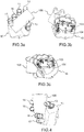
- the Figures 3a, 3b and 3c represent the hand 10 gripping an object 165 of rectangular shape, such as a mobile phone.
- the five fingers 13 to 17 are in contact with the object 165.
- the shape of the object 165 requires a different folding for each of the fingers 14 to 17 connected to the pedals 103 and 104. More specifically, the index 14 is slightly folded and in contrast, the little finger 17 is strongly folded.
- the fingers 14 to 17 connected to the spreaders 103 and 104 are substantially folded in the same way.
- the presence of the object 165 modifies the folding of the fingers 14 to 17 while maintaining a substantially constant force exerted by each of the fingers 14 to 17 on the object 165.
- the figure 4 represents the hand 10 gripping an object 166 of circular shape, such as a cup.
- the object 166 is held only by three fingers out of five.
- the object 166 is held between on the one hand the thumb 13 and on the other hand the index 14 and the middle finger 15. Thanks to the pedals 103 and 104, the two other fingers 16 and 17 fold completely until they come into for example against the palm of the hand 10.
- the equality of the forces exerted by the fingers 14 to 17 is not perfect in the case of an object such as the cup 166. Nevertheless, the efforts of the various fingers 14 to 17 are more balanced than when there is no lifter.
- the implementation of a spreader makes it possible to distribute the force exerted by the actuator associated with this spreader on the different fingers.
- the different fingers can exert a substantially constant force on an object grasped by the hand even if the shape of the object is variable.
- the figure 5 represents a variant of the hand 10 in which a double-acting actuator 170 acts on the two pedals 103 and 104.
- the two tie rods 105 and 106 shown in the variant of FIG. figure 1 are replaced by a cable 171 having two ends each attached to one of the spreaders 103 and 104. More precisely one end of the cable is formed by the protrusion 135.
- the actuator 170 is for example a rotary actuator which rotates a pulley 172.
- the cable 171 winds on the pulley. 172.
- the rotation of the pulley 172 moves the cable 171 which pulls on one of the pedals 103 and 104 and pushes on the other.
- the cable 171 is in contact with the pulley 172 about half the diameter of the pulley 172.
- the winding of the cable 171 on the pulley 172 makes it possible to transmit a torque depending on the cable length 171 in contact with the pulley 172.
- the transmitted torque is also a function of the coefficient of friction of the cable 171 relative to the pulley 172 and therefore the nature of the materials in contact chosen for the cable 171 and the pulley 172. It is possible to define these materials to achieve a torque limiter and therefore a force limiter on the fingers 14 to 17. For example if a large external force is applied to the fingers 14 to 17, we can allow the cable 171 to slide relative to the pulley 172 in particular to protect the actuator 170.
- any slippage of the cable 171 relative to the pulley 172 especially if the actuator 170 is provided with a position sensor for determining the position of the fingers 14 to 17.
- the actuator 170 is provided with a position sensor for determining the position of the fingers 14 to 17.
- the figure 6 represents another variant of the hand 10 having only one spreader 103 actuated by a cable 175 and a double effect actuator 176.
- Each finger 14 to 17 comprises an elastic member, such as a spring tending to hold the fingers 14 to 17 in an extreme position, either folded or extended.
- the actuator 176 allows each of the fingers to move away from its extreme position. For example, the fingers 14 to 17 held in extended position by a spring are folded by means of the actuator 176.
- the figure 7 presents a variant of the figure 6 in which the return spring is common to all the fingers 14 to 17.
- the return spring is common to all the fingers 14 to 17.
- the spreader 103 is connected to the actuator 176 via the cable 175.
- the lifter 104 is connected to the body of the palm 11 by means of a spring 178.
- Another configuration consists in using the two spreaders 103 and 104 to act each on different phalanges of the fingers 14 to 17.
- the two actuators 101 and 102 are then independent.
- the actuator 170 or 176 exerts a force on the thumb 13 independently of the or pedals 103 and 104.
- the actuator 170 rotates a second pulley 180 on which a cable 181 is wound, making it possible to transmit a force to the thumb 13.
- the cable 181 makes it possible to fold and extend the thumb 13.
- the cables 171 and 181 each associated with a pulley 172 and 180 are configured to fold the thumb 13 and the others 14 to 17 during the same rotation of the actuator 170.
- a reverse rotation of the actuator 170 extends the thumb 13 and the other fingers 14 to 17.
- the hand 10 comprises stops limiting the displacement of the or pedals 103 and 104.
- the abutments 161 and 162 are for example formed in the palm 10 at the fingers 14 and 17
- the pedals 103 and 104 bear against one or against the two stops 161 and 162 when the corresponding tie rods are at the end of the race. More specifically, the lifter 104 abuts against the stop 161 when the index 14 is stretched to the desired maximum.
- the support of the spreader 104 on the stop 161 prevents a reversal of the index 14 beyond its extended position. This reversal would be similar to a dislocation of one of the joints of the phalanges in human anatomy. In other words the support on the stop limits the angular movement of the joints of the finger considered.
- the support of the spreader 104 against the abutment 162 allows, in the same way, to limit the extension of the little finger 17.
- the two stops 161 and 162 arranged at the end fingers 14 and 17 are sufficient to limit the extension of all the fingers associated with the spreader bar 104.
- the spreader bar 103 can also bear on the stops 161 and 162 in order to limit the folding of the fingers 14 to 17.
- the figure 8 represents the open hand palm side view. This view allows to specify the position of the application points of the fingers connected to the rudder and the orientation of the fingers between them. More specifically, using the figure 2b it has been pointed out that with respect to the frontal direction 152, the abscissa of the projections of the application points 147 to 150 on the spreader 103 are all negative. The origin of the abscissa is the projection of the application point 145 of the force applied by the actuator. It is possible to get closer to the human anatomy by differentiating the different abscissae from the projections of the application points 147 to 150 on the frontal direction 152.
- the abscissa of the application point 150 of the effort F4 exerted by the little finger 17 is the smallest.
- the abscissa of the point of application 148 of the force F2 exerted by the middle finger 15 is the largest.
- the abscissa of the application points 147 and 149 of the forces F1 and F3 exerted by the index 14 and the ring 16 have intermediate values between the abscissa of the application points 148 and 150.
- the four fingers 14 to 17 connected to the lifter are identical. This simplifies their manufacture by standardizing the mechanical parts that compose them.
- the fingers of the hand 10 are identical, which is not the case in a human hand, the fact of shifting the application points 147 to 150 and thus the attachment of the fingers on the palm 11 allows the 10 to get closer to the human anatomy with regard to the arrangement of the ends of the fingers 14 to 17.
- the four fingers 14 to 17 so that, when the fingers close, the ends of each finger tend to get closer. More precisely, with respect to the direction in which the force F5 is applied, the directions along which the fingers extend, connected to the rudder considered, are angularly open, especially since the point of application of the finger in question is remote. from the direction according to which the effort F5 is applied.
- direction in which extends a finger means a main direction of the finger when it is extended.
- the middle and the annular extend in directions each making an angle of about 6 ° with the direction in which the force F5 is applied.
- the annular 16 and the little finger 17 extend in directions forming an angle of about 12 ° between them.
- the index 14 and the middle finger 15 extend in directions that make an angle of about 12 ° between them. By closing the ends of the fingers are approaching, which facilitates the gripping between the four fingers 14 to 17 and the thumb 13. It is understood that these angular values are given by way of example. Other values are of course possible.
- the figure 8 represents a humanoid robot 200 having two hands 10.
Landscapes
- Engineering & Computer Science (AREA)
- Robotics (AREA)
- Mechanical Engineering (AREA)
- Manipulator (AREA)
- Prostheses (AREA)
- User Interface Of Digital Computer (AREA)
Description
- L'invention concerne une main destinée à équiper un robot à caractère humanoïde.
- La main humaine est une partie du corps humain extrêmement complexe. Elle comprend plusieurs doigts articulés autour de la paume de la main. Par ailleurs chaque doigt possède plusieurs phalanges articulées entre elles. Chaque articulation est mobile au moyen de muscles. Les différentes articulations de la main permettent notamment la préhension d'objets de formes diverses. De nombreuses tentatives ont été réalisées dans des robots à caractère humanoïde afin de se rapprocher au mieux des fonctionnalités humaines. La fonction préhension est l'une des fonctions les plus difficiles à réaliser par un système robotisé, elle nécessite un grand nombre d'actionneurs indépendants pour assurer la préhension d'objets divers. Ceci augmente la complexité du robot tant au niveau du nombre d'actionneurs indépendants à prévoir qu'au niveau du pilotage de ces différents actionneurs que l'on doit commander de façon coordonnée.
- Les documents
WO 2010/018358 A2 ,CN 203 236 487 U ,JP 2003 145474 A US 2004/054424 A1 décrivent des mains robotisées dans lesquelles plusieurs doigts sont actionnés par un même actionneur. - L'invention vise à proposer une main d'un robot à caractère humanoïde possédant plusieurs doigts et permettant de s'adapter facilement à la forme de divers objets en réduisant le nombre d'actionneurs indépendants pour chacun des doigts de la main.
- A cet effet, l'invention a pour objet une main destinée à équiper un robot à caractère humanoïde, la main comprenant une paume et plusieurs doigts motorisés par rapport à la paume, un actionneur commun à plusieurs doigts et un palonnier permettant de répartir un effort exercé par l'actionneur vers les doigts. De plus, l'invention se caractérise en ce qu'on définit dans un plan dit plan frontal perpendiculaire à une direction dans laquelle est orienté l'effort exercé par l'actionneur, la projection du point d'application sur le palonnier de l'effort exercé par l'actionneur et les projections des points d'application sur le palonnier des efforts exercés par les doigts. On définit dans le plan frontal une direction dite direction verticale perpendiculaire à l'intersection du plan frontal et d'un plan dit plan horizontal contenant une direction dans laquelle est orienté l'effort exercé par l'actionneur et dans lequel s'étend principalement la paume de la main. Selon la direction verticale, la projection du point d'application sur le palonnier de l'effort exercé par l'actionneur est disposée sensiblement au barycentre des projections des points d'application sur le palonnier des efforts exercés par les doigts, les projections des points d'application sur le palonnier des efforts exercés par les doigts n'étant pas toutes confondues.
- Le terme palonnier est souvent utilisé dans le domaine aéronautique. Par analogie, on entend par palonnier toute pièce mécanique permettant de répartir des efforts. La répartition se fait en fonction de la disposition géométrique des points d'appuis de chacun des efforts sur la pièce mécanique. La répartition conserve un état d'équilibre de la pièce mécanique. Lorsque les efforts appliqués à la pièce mécanique évoluent lentement, il est possible de déterminer les différents efforts à partir d'équations d'équilibre statique. Dans l'invention, le palonnier permet de répartir l'effort d'un actionneur unique vers plusieurs doigts. La présence d'un palonnier permet d'améliorer la compliance de la main vis-à-vis de la forme des objets qu'elle est susceptible de rencontrer. On entend par compliance de la main, sa capacité à s'ajuster aux contraintes et aux forces qui s'exercent sur elle.
- La mise en oeuvre d'un palonnier permet à la main de se refermer en reproduisant un mouvement fluide et naturel proche de celui d'un humain. Le fait d'associer un seul actionneur à un palonnier permet de synchroniser parfaitement le mouvement des différents doigts reliés au palonnier.
- L'invention a également pour objet un robot à caractère humanoïde comprenant une main selon l'invention.
- On entend par robot à caractère humanoïde, un robot présentant des similitudes avec le corps humain. Il peut s'agir du haut du corps, ou uniquement d'un bras articulé se terminant par une pince assimilable à une main humaine. Dans la présente invention, le fonctionnement de la main du robot est similaire à celui d'une main humaine. Une main conforme à l'invention permet de saisir des objets grâce aux mouvements de ses doigts et aux efforts qu'ils peuvent exercer sur un objet.
- L'invention sera mieux comprise et d'autres avantages apparaîtront à la lecture de la description détaillée d'un mode de réalisation donné à titre d'exemple, description illustrée par le dessin joint dans lequel :
- la
figure 1 représente en perspective une main destinée à équiper un robot à caractère humanoïde ; - les
figures 2a, 2b et 2c représentent un palonnier de la main dans différentes vues en plan ; - les
figures 3a, 3b et 3c représentent la main saisissant un objet ; - la
figure 4 représente la main saisissant un autre objet ; - les
figures 5, 6 et7 représentent en perspective plusieurs variantes de la main ; - la
figure 8 représente la main ouverte vue coté paume ; - la
figure 9 représente un robot à caractère humanoïde mettant en oeuvre la main de l'invention. - Par souci de clarté, les mêmes éléments porteront les mêmes repères dans les différentes figures.
- La
figure 1 représente une main 10 destinée à équiper un robot à caractère humanoïde. La main 10 comprend une paume 11 et cinq doigts 13 à 17. Les doigts sont articulés à la paume 11 de façon à permettre la préhension d'objets entre les doigts 13 à 17. A l'image d'une main humaine, le doigt 13 est un pouce. Un objet saisi par la main est maintenu entre le pouce 13 et les autres doigts 14 à 17. L'invention n'est pas limitée à une main possédant cinq doigts. Il est possible de réduire le nombre de doigts pour simplifier la conception de la main ou même d'augmenter le nombre de doigts pour permettre la préhension d'objets particuliers. - De façon plus générale, une main de l'invention peut être formée d'une pince permettant de saisir un objet. La pince comprend au moins deux doigts articulés permettant plusieurs points de contact avec l'objet saisi. En regard de ces doigts articulés, il est possible de disposer un doigt fixe ou même directement la paume de la main.
- Selon l'invention, la main 10 comprend un actionneur commun à plusieurs doigts et un palonnier permettant de répartir un effort exercé par l'actionneur vers les doigts. Dans l'exemple représenté
figure 1 , la main 10 comprend deux actionneurs 101 et 102 ainsi que deux palonniers 103 et 104. L'actionneur 101 est relié au palonnier 103 au moyen d'un tirant 105 et l'actionneur 102 est relié au palonnier 104 au moyen d'un tirant 106. Le palonnier 103 peut exercer un effort sur les quatre doigts 14 à 17 respectivement par l'intermédiaire de tirants 107, 108, 109 et 110. De même, le palonnier 104 peut exercer un effort sur les quatre doigts 14 à 17 respectivement par l'intermédiaire de tirants 117, 118, 119 et 120. - Les actionneurs 101 et 102 peuvent être des actionneurs linéaires tels que des vérins. Tout autre type d'actionneur peut être mis en oeuvre dans le cadre de l'invention, comme par exemple des actionneurs rotatifs ou des muscles artificiels.
- Dans l'exemple représenté
figure 1 , les palonniers 103 et 104 permettent de répartir un effort vers quatre doigts représentant l'index 14, le majeur 15, l'annulaire 16 et l'auriculaire 17. Il est également possible d'inclure le pouce 13 dans la répartition. De façon plus générale le ou les palonniers 103 et 104 permettent de répartir un effort exercé par le ou les actionneurs 101 et 102 vers le pouce 13 et au moins un autre doigt 14 à 17. - Les deux palonniers 103 et 104 s'étendent principalement chacun dans un plan dit plan horizontal contenant une direction dans laquelle est orienté l'effort exercé par l'actionneur associé et dans lequel s'étend principalement la paume de la main 10.
- Un doigt peut être actionné par deux tirants, par exemple les tirants 107 et 117 pour l'index 14, l'un pour tendre le doigt 14 et l'autre pour le replier. Les deux tirants 107 et 117 agissent alors de manière coordonnée. Les actionneurs 101 et 102 agissent également de manière coordonnée. On peut utiliser un actionneur unique qui tire sur l'un des tirants 105 ou 106 et pousse sur l'autre simultanément. La main 10 comprend deux palonniers 103 et 104 permettant de motoriser chacun des doigts 14, 15, 16 et 17. Le palonnier 103 permet de tendre les doigts qui lui sont raccordés et donc ouvrir la main 10. Le palonnier 104 permet de replier les doigts qui lui sont raccordés et donc fermer la main 10.
- On définit un repère lié la paume 11 de la main 10. La paume s'étend principalement dans un plan 125 dit plan horizontal. Lorsque les doigts 14 à 17 sont complètement dépliés ou ouverts, ils s'étendent dans le plan 125. Dans la configuration représentée sur la
figure 1 , les palonniers 103 et 104 s'étendent principalement dans le plan horizontal 125. Les tirants 105 et 106 s'étendent également dans le plan horizontal 125. En conséquence, les directions dans lesquelles les efforts sont exercés par les actionneurs 101 et 102 sont contenues dans le plan 125. - On définit un plan frontal 126 perpendiculaire au plan horizontal 125 et aux directions dans lesquelles sont orientés les efforts exercés par les actionneurs 101 et 102.
- On définit enfin un troisième plan 127 dit plan vertical perpendiculaire aux plans 125 et 126. Lorsque les doigts 14 à 17 se referment ou s'étendent, les phalanges se déplacent essentiellement dans un plan vertical.
- La
figure 2a représente un des palonniers, par exemple le palonnier 103 en projection dans un plan frontal. - La
figure 2b représente le même palonnier 103 en projection dans un plan horizontal et lafigure 2c représente le palonnier 103 dans un plan vertical. - Le palonnier 103 s'étend principalement dans un plan horizontal. Il peut néanmoins présenter une certaine courbe par rapport à ce plan. Cette courbe est bien visible sur la
figure 2a . Sur cette figure apparaissent les projections, dans le plan frontal, des points d'application des différents efforts sur le palonnier 103. Plus précisément, les tirants 105, 107, 108, 109 et 110 peuvent être des câbles dont les extrémités présentent des excroissances, respectivement 135, 137, 138, 139 et 140 serties ou moulées sur une extrémité du câble. Les excroissances de chacun des câbles sont maintenues dans des gorges réalisées dans le palonnier 103. Les points d'application des efforts sont les points de contact des excroissances avec le palonnier 103. L'effort exercé par l'actionneur 101 sur le palonnier 103 est repéré F5. Les efforts exercés par les doigts 14, 15, 16 et 17 sont repérés respectivement F1, F2, F3 et F4. Le point d'application de l'effort exercé par l'actionneur 101 par l'intermédiaire du tirant 105 porte le repère 145. Le point d'application de l'effort exercé par le tirant 107 porte le repère 147. Le point d'application de l'effort exercé par le tirant 108 porte le repère 148. Le point d'application de l'effort exercé par le tirant 109 porte le repère 149 et le point d'application de l'effort exercé par le tirant 110 porte le repère 150. - Dans le plan frontal 126, on définit une direction verticale 142 perpendiculaire à l'intersection du plan frontal 126 et du plan horizontal 125. La projection du point d'application 145 de l'effort exercé par l'actionneur 101 est avantageusement disposée sensiblement au barycentre des projections des points d'application 137 à 140 des efforts exercés par les doigts 14 à 17.
- Plus précisément, sur la direction verticale 142, on définit comme origine l'abscisse de la projection du point d'application 145. La somme des abscisses des projections des points d'application 147 à 150 est nulle. Les projections sur la direction verticale 142 des points d'application 147 à 150 sur le palonnier 103 des efforts F1 à F4 exercés par les doigts 14 à 17 ne sont pas toutes confondues.
- Cette position relative des différents points d'application des efforts F1 à F5 sur le palonnier 103 permet de conserver une position stable du palonnier 103 dans la paume 11 de la main 10. En effet, les efforts F1 à F4 exercés par les doigts sur le palonnier 103 peuvent évoluer en fonction de la forme d'un objet saisi par la main 10. La position relative des différents points d'application des efforts F1 à F5 sur le palonnier 103 ainsi définie permet de maintenir le palonnier 103 dans une position relative par rapport au plan horizontal 125 sensiblement constante. Le palonnier 103 peut se déplacer en translation selon une direction sensiblement portée par le plan horizontal 125.
- Par ailleurs, on définit une direction frontale 152, visible sur la
figure 2b . La direction 152 est parallèle à la direction dans laquelle est orienté l'effort F5 exercé par l'actionneur 101. Selon la direction frontale 152, on considère la projection du point d'application 145 sur le palonnier 103 de l'effort F5 exercé par l'actionneur 101 comme origine, et comme sens positif le sens dans lequel l'actionneur 101 tire sur le palonnier 103. Les abscisses des projections des points d'application 147 à 150 sur le palonnier 103 des efforts F1 à F4 exercés par les doigts 14 à 17 sont toutes négatives. - Cette position relative des différents points d'application des efforts F1 à F5 sur le palonnier 103 permet d'éviter tout arc-boutement du palonnier 103 dans la paume 11 de la main 10.
- On peut enfin définir une troisième direction 162 perpendiculaire aux directions 142 et 152. Selon la direction 162, la projection du point d'application 145 de l'effort exercé par l'actionneur 101 est avantageusement disposée sensiblement au milieu des projections des points d'application 148 et 149. De même, toujours selon la direction 162, la projection du point d'application 145 est avantageusement disposée sensiblement au milieu des projections des points d'application 147 et 150. Autrement dit, selon la direction 162, on définit plusieurs distances séparant la projection du point d'application 145 des autres projections : L1 pour la projection du point 148, L2 pour la projection du point 149, L3 pour la projection du point 147 et L4 pour la projection du point 150. Avantageusement, on a L1 = L2 et L3 = L4.
- Le respect de la position du point d'application 145 au milieu des doigts deux à deux permet de répartir de façon équilibrée les efforts de l'actionneur 101 vers les différents doigts 14 à 17. Autrement dit pour une traction donnée réalisée par l'actionneur 101, l'effort exercé sur chacun des quatre doigts 14 à 17 est égal au quart de l'effort exercé par l'actionneur 101.
- Il est possible de généraliser cette disposition quelque soit le nombre de doigts raccordés au palonnier 103. Plus précisément, selon la direction 162, la projection du point d'application 145 de l'effort exercé par l'actionneur 101 est située au barycentre de la projection des points d'application des efforts exercés par les doigts 14 à 17 reliés au palonnier 103.
- Une répartition équilibrée des efforts sur les différents doigts reliés au palonnier permet d'adopter une préhension des objets saisis proche d'une préhension humaine quelle que soit leur forme, même en présence d'un seul actionneur 101.
- Les
figures 3a, 3b et 3c représentent la main 10 saisissant un objet 165 de forme rectangulaire, comme par exemple un téléphone portable. Les cinq doigts 13 à 17 sont en contact avec l'objet 165. La forme de l'objet 165 nécessite un repliement différent pour chacun des doigts 14 à 17 reliés aux palonniers 103 et 104. Plus précisément, l'index 14 est faiblement replié et à l'opposé, l'auriculaire 17 est fortement replié. Sur lafigure 1 , en l'absence d'objet saisi, les doigts 14 à 17 reliés aux palonniers 103 et 104 sont sensiblement repliés de la même façon. La présence de l'objet 165 modifie le repliement des doigts 14 à 17 tout en conservant un effort sensiblement constant exercé par chacun des doigts 14 à 17 sur l'objet 165. - Une rotation s'est opérée entre les palonniers 103 et 104 pour s'adapter à l'objet 165. Cette rotation est visible entre d'une part la
figure 1 , en l'absence d'objet saisi, et d'autre part lesfigures 3a à 3c en présence de l'objet 165. La présence d'un ou de deux palonniers permet à la main de s'adapter à la forme de l'objet saisi. - La
figure 4 représente la main 10 saisissant un objet 166 de forme circulaire, comme par exemple un gobelet. L'objet 166 est uniquement tenu par trois doigts sur cinq. L'objet 166 est tenu entre d'une part le pouce 13 et d'autre part l'index 14 et le majeur 15. Grâce aux palonniers 103 et 104, les deux autres doigts 16 et 17 se replient complètement jusqu'à venir en butée par exemple contre la paume de la main 10. L'égalité des efforts exercés par les doigts 14 à 17 n'est pas parfaite dans le cas d'un objet tel que le gobelet 166. Néanmoins, les efforts des différents doigts 14 à 17 sont plus équilibrés qu'en l'absence de palonnier. - De façon générale la mise en oeuvre d'un palonnier permet de répartir l'effort exercé par l'actionneur associé à ce palonnier sur les différents doigts. Ainsi les différents doigts peuvent exercer un effort sensiblement constant sur un objet saisi par la main même si la forme de l'objet est variable.
- Alternativement, il est possible de s'éloigner de l'équilibre obtenu en positionnant le point d'application 145 de l'actionneur 101 au barycentre des points d'application 147 à 150 des tirants reliés aux doigts 14 à 17. On peut par exemple déplacer le point d'application 145 vers l'index 14 et ainsi distribuer plus d'efforts vers l'index 14. L'index 14 aura tendance à se refermer en avance par rapport aux autres doigts. L'index 14 exerce alors un effort plus important que les autres doigts sur l'objet saisi.
- A l'extrême il est possible d'aligner le point d'application 147 de l'index de la main 10 avec le point d'application 145 de l'actionneur 101. Ceci permet d'assurer une préhension d'un objet uniquement entre le pouce 13 et l'index 14.
- La
figure 5 représente une variante de la main 10 dans laquelle un actionneur double effet 170 agit sur les deux palonniers 103 et 104. Les deux tirants 105 et 106 représentés dans la variante de lafigure 1 sont remplacés par un câble 171 possédant deux extrémités fixées chacune à l'un des palonniers 103 et 104. Plus précisément une extrémité du câble est formée par l'excroissance 135. L'autre extrémité du câble 171, non visible sur lafigure 5 , est semblable et est fixée au palonnier 104. L'actionneur 170 est commun aux deux palonniers 103 et 104. L'actionneur 170 est par exemple un actionneur rotatif qui entraine en rotation une poulie 172. Le câble 171 s'enroule sur la poulie 172. La rotation de la poulie 172 déplace le câble 171 qui tire sur l'un des palonniers 103 et 104 et pousse sur l'autre. - Lorsque les deux palonniers 103 et 104 sont sensiblement parallèles, le câble 171 est en contact avec la poulie 172 sur environ la moitié du diamètre de la poulie 172. L'enroulement du câble 171 sur la poulie 172 permet de transmettre un couple fonction de la longueur de câble 171 en contact avec la poulie 172. Le couple transmis est également fonction du coefficient de frottement du câble 171 par rapport à la poulie 172 et donc de la nature des matériaux en contact choisis pour le câble 171 et pour la poulie 172. Il est possible de définir ces matériaux pour réaliser un limiteur de couple et donc un limiteur d'effort sur les doigts 14 à 17. Par exemple si un effort extérieur important est appliqué aux doigts 14 à 17, on peut permettre au câble 171 de glisser par rapport à la poulie 172 notamment pour protéger l'actionneur 170.
- Alternativement, on peut souhaiter éviter tout glissement du câble 171 par rapport à la poulie 172, notamment si l'actionneur 170 est muni d'un capteur de position permettant de déterminer la position des doigts 14 à 17. Pour éviter tout glissement, on peut par exemple enrouler le câble 171 sur plus d'un tour autour de la poulie 171. Il est également possible de fixer le câble 171 à la poulie.
- La
figure 6 représente une autre variante de la main 10 ne possédant qu'un seul palonnier 103 actionné par un câble 175 et un actionneur 176 double effet. Chaque doigt 14 à 17 comprend un élément élastique, comme par exemple un ressort tendant à maintenir les doigts 14 à 17 dans une position extrême, soit repliée soit en extension. Par l'intermédiaire du palonnier 103, l'actionneur 176 permet à chacun des doigts de s'éloigner de sa position extrême. Par exemple, les doigts 14 à 17 maintenus en position d'extension par un ressort sont repliés au moyen de l'actionneur 176. - La
figure 7 présente une variante de lafigure 6 dans laquelle le ressort de rappel est commun à tous les doigts 14 à 17. On retrouve dans cette variante les deux palonniers 103 et 104. Comme dans la variante de lafigure 6 , le palonnier 103 est relié à l'actionneur 176 par l'intermédiaire du câble 175. De plus le palonnier 104 est relié au corps de la paume 11 par l'intermédiaire d'un ressort 178. Ainsi lorsque l'actionneur 176 tire sur le palonnier 103, un effort de rappel commun aux doigts 14 à 17 est appliqué grâce au palonnier 104. L'effort de rappel est réparti sur les doigts 14 à 17 par le palonnier 104. - Une autre configuration consiste à utiliser les deux palonniers 103 et 104 pour agir chacun sur des phalanges différentes des doigts 14 à 17. Les deux actionneurs 101 et 102 sont alors indépendants.
- Dans les variantes représentées sur les
figures 5, 6 et7 , l'actionneur 170 ou 176 exerce un effort sur le pouce 13 indépendamment du ou des palonniers 103 et 104. - A cet effet, dans la variante de la
figure 5 , l'actionneur 170 entraine en rotation une seconde poulie 180 sur laquelle s'enroule un câble 181 permettant de transmettre un effort au pouce 13. Comme le câble 171, le câble 181 permet de replier et d'étendre le pouce 13. On peut prévoir deux poulies libres 182 sur lesquelles s'appuie le câble 181 pour modifier sa direction entre l'actionneur 170 et le pouce 13. Les câbles 171 et 181 associés chacun à une poulie 172 et 180 sont configurés pour replier le pouce 13 et les autres doigts 14 à 17 lors d'une même rotation de l'actionneur 170. Une rotation inverse de l'actionneur 170 permet d'étendre le pouce 13 et les autres doigts 14 à 17. Ainsi un seul actionneur permet de refermer la main 10 ou de l'ouvrir sur objet saisi. - Cette configuration où le pouce 13 et les quatre autres doigts 14 à 17 sont commandés par le même actionneur est transposable dans les autres variantes des
figures 6 et7 . Ainsi dans la variante de lafigure 6 , le pouce 13 est actionné par un câble 185 relié à l'actionneur 176 indépendamment du palonnier 103. Dans la variante de lafigure 7 , un effort de rappel est exercé sur le pouce 13 par l'intermédiaire d'un ressort 188. Cet effort de rappel s'oppose à l'effort exercé par le câble 185. - Avantageusement, la main 10 comprend des butées limitant le déplacement du ou des palonniers 103 et 104. Des butées 161 et 162 sont par exemple formées dans la paume 10 au niveau des doigts 14 et 17 Les palonniers 103 et 104 prennent appui contre l'une ou contre les deux butées 161 et 162 lorsque les tirants correspondant sont en bout de course. Plus précisément, le palonnier 104 vient en appui contre la butée 161 lorsque l'index 14 se tend au maximum souhaité. L'appui du palonnier 104 sur la butée 161 évite un retournement de l'index 14 au-delà de sa position tendue. Ce retournement serait semblable à une luxation d'une des articulations des phalanges en anatomie humaine. Autrement dit l'appui sur la butée permet de limiter le débattement angulaire des articulations du doigt considéré. L'appui du palonnier 104 contre la butée 162 permet, de la même façon, de limiter l'extension de l'auriculaire 17. Les deux butées 161 et 162 disposées au niveau des doigts extrêmes 14 et 17 suffisent pour limiter l'extension de tous les doigts associés au palonnier 104. De même, le palonnier 103 peut également venir en appui sur les butées 161 et 162 afin de limiter le repli des doigts 14 à 17.
- la
figure 8 représente la main ouverte vue coté paume. Cette vue permet de préciser la position des points d'applications des doigts reliés au palonnier et l'orientation des doigts entre eux. Plus précisément, à l'aide de lafigure 2b , on a précisé que par rapport à la direction frontale 152, les abscisses des projections des points d'application 147 à 150 sur le palonnier 103 sont toutes négatives. L'origine des abscisses est la projection du point d'application 145 de l'effort appliqué par l'actionneur. Il est possible de mieux se rapprocher de l'anatomie humaine en différenciant les différentes abscisses des projections des points d'application 147 à 150 sur la direction frontale 152. Plus précisément, en valeur absolue, l'abscisse du point d'application 150 de l'effort F4 exercé par l'auriculaire 17 est la plus petite. En valeur absolue, l'abscisse du point d'application 148 de l'effort F2 exercé par le majeur 15 est la plus grande. En valeur absolue, les abscisses des points d'application 147 et 149 des efforts F1 et F3 exercés par l'index 14 et l'annulaire 16 ont des valeurs intermédiaires comprises entre l'abscisse des points d'application 148 et 150. - Avantageusement, les quatre doigts 14 à 17 reliés au palonnier sont identiques. Cela permet de simplifier leur fabrication en standardisant les pièces mécaniques qui les composent. Bien que les doigts de la main 10 soient identiques, ce qui n'est pas le cas dans une main humaine, le fait de décaler les points d'application 147 à 150 et donc l'accrochage des doigts sur la paume 11 permet à la main 10 de se rapprocher de l'anatomie humaine en ce qui concerne la disposition des extrémités des doigts 14 à 17.
- Par ailleurs, il est possible d'orienter différemment dans le plan frontal les quatre doigts 14 à 17 de façon à ce que, lorsque les doigts se referment, les extrémités de chacun des doigts tendent à se rapprocher. Plus précisément, par rapport à la direction selon laquelle l'effort F5 est appliqué, les directions selon lesquelles s'étendent les doigts reliés au palonnier considéré, s'ouvrent angulairement d'autant plus que le point d'application du doigt considéré est éloigné de la direction selon laquelle l'effort F5 est appliqué. Par direction selon laquelle s'étend un doigt, on entend une direction principale du doigt lorsque celui-ci est en extension. Dans l'exemple représenté, le majeur et l'annulaire s'étendent selon des directions faisant chacune un angle d'environ 6° avec la direction selon laquelle l'effort F5 est appliqué. L'annulaire 16 et l'auriculaire 17 s'étendent selon des directions faisant entre elles un angle d'environ 12°. De même, l'index 14 et le majeur 15 s'étendent selon des directions faisant entre elles un angle d'environ 12°. En se refermant les extrémités des doigts se rapprochent, ce qui facilite la préhension entre les quatre doigts 14 à 17 et le pouce 13. Il est bien entendu que ces valeurs angulaires ne sont données qu'à titre d'exemple. D'autres valeurs sont bien entendu possibles.
- La
figure 8 représente un robot à caractère humanoïde 200 possédant deux mains 10.
Claims (13)
- Main destinée à équiper un robot à caractère humanoïde, la main (10) comprenant une paume (11) et plusieurs doigts (13, 14, 15, 16, 17) motorisés par rapport à la paume (11), un actionneur (101, 102 ; 170 ; 176) commun à plusieurs doigts (13, 14, 15, 16, 17) et un palonnier (103, 104) permettant de répartir un effort (F5) exercé par l'actionneur (101, 102) vers les doigts (14, 15, 16, 17),
caractérisée en ce qu'on définit dans un plan dit plan frontal (126) perpendiculaire à une direction dans laquelle est orienté l'effort exercé par l'actionneur (101, 102), la projection du point d'application (145) sur le palonnier (103) de l'effort (F5) exercé par l'actionneur (101) et les projections des points d'application (147, 148, 149, 150) sur le palonnier (103) des efforts (F1, F2, F3, F4) exercés par les doigts (14, 15, 16, 17), en ce qu'on définit dans le plan frontal (126) une direction dite direction verticale (142) perpendiculaire à l'intersection du plan frontal (126) et d'un plan dit plan horizontal (125) contenant une direction dans laquelle est orienté l'effort (F5) exercé par l'actionneur (101) et dans lequel s'étend principalement la paume (11) de la main (10) et en ce que selon la direction verticale (142), la projection du point d'application (145) sur le palonnier (103) de l'effort (F5) exercé par l'actionneur (101) est disposée sensiblement au barycentre des projections des points d'application (147, 148, 149, 150) sur le palonnier (103) des efforts (F1, F2, F3, F4) exercés par les doigts (14, 15, 16, 17), les projections des points d'application (147, 148, 149, 150) sur le palonnier (103) des efforts (F1, F2, F3, F4) exercés par les doigts (14, 15, 16, 17) n'étant pas toutes confondues. - Main selon la revendication 1, caractérisée en ce qu'on définit dans un plan dit plan horizontal (125) contenant une direction dans laquelle est orienté l'effort (F5) exercé par l'actionneur (101) et dans lequel s'étend principalement la paume (11) de la main (10), la projection du point d'application (145) sur le palonnier (103) de l'effort (F5) exercé par l'actionneur (101) et les projections des points d'application (147, 148, 149, 150) sur le palonnier (103) des efforts (F1, F2, F3, F4) exercés par les doigts (14, 15, 16, 17), en ce qu'on définit une direction dite direction frontale (152) parallèle à la direction dans laquelle est orienté l'effort (F5) exercé par l'actionneur (101), et en ce que selon la direction frontale (152), en considérant la projection du point d'application (145) sur le palonnier (103) de l'effort (F5) exercé par l'actionneur (101) comme origine, et comme sens positif le sens dans lequel l'actionneur (101) tire sur le palonnier (103), les abscisses des projections des points d'application (147, 148, 149, 150) sur le palonnier (103) des efforts (F1, F2, F3, F4) exercés par les doigts (14, 15, 16, 17) sont toutes négatives.
- Main selon la revendication 2, caractérisée en ce qu'elle comprend quatre doigts (14, 15, 16, 17) reliés au palonnier (103, 104), dont un premier doigt forme un index (14), un deuxième forme un majeur (15) un troisième forme un annulaire (16) et un quatrième forme un auriculaire (17), en ce que, par rapport à la direction frontale (152) et en valeur absolue, l'abscisse du point d'application (150) de l'effort (F4) exercé par l'auriculaire (17) est la plus petite, l'abscisse du point d'application (148) de l'effort (F2) exercé par le majeur (15) est la plus grande et, les abscisses des points d'application (147, 149) des efforts (F1, F3) exercé par l'index (14) et l'annulaire (16) ont des valeurs intermédiaires.
- Main selon la revendication 3, caractérisée en ce que les quatre doigts (14, 15, 16, 17) reliés au palonnier (103, 104) sont identiques.
- Main selon l'une des revendications précédentes, caractérisée en ce qu'on définit dans un plan dit plan horizontal (125) contenant une direction dans laquelle est orienté l'effort (F5) exercé par l'actionneur (101) et dans lequel s'étend principalement la paume (11) de la main (10), la projection du point d'application (145) sur le palonnier (103) de l'effort (F5) exercé par l'actionneur (101) et les projections des points d'application (147, 148, 149, 150) sur le palonnier (103) des efforts (F1, F2, F3, F4) exercés par les doigts (14, 15, 16, 17), en ce que selon une direction (162) du plan horizontal (125) perpendiculaire à la direction dans laquelle est orienté l'effort (F5) exercé par l'actionneur (101), la projection du point d'application (145) de l'effort exercé par l'actionneur (101) est située au barycentre de la projection des points d'application des efforts (F1, F2, F3, F4) exercés par les doigts (14, 15, 16, 17) reliés au palonnier (103).
- Main selon l'une des revendications précédentes, caractérisée en ce que le palonnier (103, 104) s'étend principalement dans un plan dit plan horizontal (125) contenant une direction dans laquelle est orienté l'effort (F5) exercé par l'actionneur (101) et dans lequel s'étend principalement la paume (11) de la main (10).
- Main selon l'une des revendications précédentes, caractérisée en ce que l'actionneur est un actionneur double effet (176) et en ce qu'elle comprend un seul palonnier (103) relié à l'actionneur double effet (176).
- Main selon l'une des revendications 1 à 6, caractérisée en ce qu'elle comprend deux palonniers (103, 104) permettant de motoriser chacun des doigts (14, 15, 16, 17) en double effet.
- Main selon la revendication 8, caractérisée en ce qu'elle comprend un actionneur double effet (170) commun aux deux palonniers (103, 104).
- Main selon la revendication 9, caractérisée en ce que l'actionneur commun (170) aux deux palonniers (103, 104) agit sur les deux palonniers (103, 104) par l'intermédiaire d'un câble (171) s'enroulant sur une poulie (172) entrainée en rotation par l'actionneur commun (170) aux deux palonniers (103, 104).
- Main selon l'une des revendications précédentes, caractérisée en ce qu'elle comprend des butées (161, 162) limitant le déplacement du palonnier (103, 104).
- Main selon l'une des revendications précédentes, caractérisée en ce qu'elle comprend un pouce (13) et en ce que l'actionneur (170 ; 176) exerce un effort sur le pouce (13) indépendamment du palonnier (103, 104).
- Robot à caractère humanoïde caractérisé en ce qu'il comprend une main (10) selon l'une des revendications précédentes.
Applications Claiming Priority (2)
| Application Number | Priority Date | Filing Date | Title |
|---|---|---|---|
| FR1450531A FR3016542B1 (fr) | 2014-01-22 | 2014-01-22 | Actionnement d'une main destinee a equiper un robot a caractere humanoide |
| PCT/EP2015/051235 WO2015110521A1 (fr) | 2014-01-22 | 2015-01-22 | Actionnement d'une main destinée à équiper un robot à caractère humanoïde |
Publications (2)
| Publication Number | Publication Date |
|---|---|
| EP3105018A1 EP3105018A1 (fr) | 2016-12-21 |
| EP3105018B1 true EP3105018B1 (fr) | 2018-06-13 |
Family
ID=50639718
Family Applications (1)
| Application Number | Title | Priority Date | Filing Date |
|---|---|---|---|
| EP15701009.1A Active EP3105018B1 (fr) | 2014-01-22 | 2015-01-22 | Actionnement d'une main destinée à équiper un robot à caractère humanoïde |
Country Status (16)
| Country | Link |
|---|---|
| US (1) | US9840009B2 (fr) |
| EP (1) | EP3105018B1 (fr) |
| JP (1) | JP6466460B2 (fr) |
| KR (1) | KR102067869B1 (fr) |
| CN (1) | CN106457574B (fr) |
| AU (1) | AU2015208156B2 (fr) |
| BR (1) | BR112016016889A2 (fr) |
| CA (1) | CA2937582C (fr) |
| DK (1) | DK3105018T3 (fr) |
| ES (1) | ES2685961T3 (fr) |
| FR (1) | FR3016542B1 (fr) |
| MX (1) | MX2016009357A (fr) |
| NZ (1) | NZ722309A (fr) |
| RU (1) | RU2016133971A (fr) |
| SG (1) | SG11201605955VA (fr) |
| WO (1) | WO2015110521A1 (fr) |
Families Citing this family (20)
| Publication number | Priority date | Publication date | Assignee | Title |
|---|---|---|---|---|
| US11351042B2 (en) | 2012-08-12 | 2022-06-07 | 5Th Element Limited | Automated hand |
| FR3020775B1 (fr) | 2014-05-07 | 2019-04-19 | Aldebaran Robotics | Actionnement d’une main destinee a equiper un robot a caractere humanoide |
| DE202016009210U1 (de) * | 2015-10-05 | 2024-03-28 | 5Th Element Limited | Automatisierte Hand |
| USD783448S1 (en) * | 2015-12-15 | 2017-04-11 | Kamal Siegel | Figurine articulated hand |
| JP1573749S (fr) * | 2016-01-29 | 2017-04-10 | ||
| US11672721B2 (en) * | 2016-09-26 | 2023-06-13 | Cyberdyne, Inc. | Motion assisting apparatus |
| CN108186171B (zh) * | 2017-12-28 | 2020-08-28 | 中国科学院深圳先进技术研究院 | 一种仿生手装置及机器人 |
| CN108466290B (zh) * | 2018-03-09 | 2021-02-19 | 苏州灵猴机器人有限公司 | 机器人辅助作业系统及其辅助作业方法 |
| CN112955289B (zh) * | 2018-11-20 | 2024-12-03 | 梅尔廷株式会社 | 机械手装置 |
| CN109732639B (zh) * | 2019-02-20 | 2020-12-18 | 西安理工大学 | 一种液体等压欠驱动仿生机器人手爪 |
| CN109758276A (zh) * | 2019-02-28 | 2019-05-17 | 中国科学院深圳先进技术研究院 | 一种假肢手 |
| CN110202600A (zh) * | 2019-06-26 | 2019-09-06 | 上海恒元界机器人科技有限公司 | 拟人机器人的仿形手 |
| KR102220191B1 (ko) | 2019-08-01 | 2021-02-25 | 엘지전자 주식회사 | 로봇 핸드 및 그 제어방법 |
| WO2021216084A1 (fr) * | 2020-04-24 | 2021-10-28 | Hewlett-Packard Development Company, L.P. | Pince mécanique |
| CN111606046B (zh) * | 2020-05-30 | 2021-03-12 | 刘子涵 | 柔性握持电磁机械手 |
| KR20210156501A (ko) * | 2020-06-18 | 2021-12-27 | 한국과학기술연구원 | 핑거팁 센서모듈과, 이를 구비한 로봇핸드 및 이를 이용한 파지 방법 |
| TWI736467B (zh) | 2020-11-11 | 2021-08-11 | 財團法人工業技術研究院 | 機械手掌及其手指裝置 |
| JP7530854B2 (ja) | 2021-03-24 | 2024-08-08 | 本田技研工業株式会社 | ロボットハンド |
| DE102023002971A1 (de) * | 2023-07-20 | 2025-01-23 | Carl Stahl Gmbh | Greifvorrichtung |
| FR3158254A1 (fr) * | 2024-01-16 | 2025-07-18 | Enchanted Tools | Préhenseur robotique destiné à coopérer avec un dispositif de moyen de préhension prédéfini |
Family Cites Families (24)
| Publication number | Priority date | Publication date | Assignee | Title |
|---|---|---|---|---|
| FR514600A (fr) * | 1917-05-08 | 1921-03-14 | Heinrich Troendle | Main artificielle |
| JPS5025708B1 (fr) * | 1970-06-22 | 1975-08-26 | ||
| US3694021A (en) * | 1970-07-31 | 1972-09-26 | James F Mullen | Mechanical hand |
| JPS5212761B2 (fr) * | 1973-07-14 | 1977-04-09 | ||
| JPS5662785A (en) * | 1979-10-25 | 1981-05-28 | Kogyo Gijutsuin | Griper |
| FR2557450B1 (fr) * | 1983-10-05 | 1986-05-02 | Monestier Jacques | Perfectionnements apportes aux protheses totales de main |
| JPS6119577A (ja) * | 1984-07-06 | 1986-01-28 | 株式会社東芝 | ワ−ク搬送用ロボツト |
| US4834761A (en) * | 1985-05-09 | 1989-05-30 | Walters David A | Robotic multiple-jointed digit control system |
| US6244644B1 (en) * | 1999-01-25 | 2001-06-12 | The United States Of America As Represented By The Administrator Of The National Aeronautics And Space Administration | Compact dexterous robotic hand |
| FR2792865B1 (fr) | 1999-04-27 | 2001-06-15 | Cie Generale De Participations | Dispositif de telecommande de mouvement notamment d'organes de prehension |
| WO2002045918A1 (fr) * | 2000-12-06 | 2002-06-13 | Honda Giken Kogyo Kabushiki Kaisha | Dispositif de main multidoigt |
| JP3793785B2 (ja) * | 2001-08-31 | 2006-07-05 | 広島県 | 多指可動ロボットハンド及びその把持制御方法 |
| JP3914045B2 (ja) * | 2001-12-17 | 2007-05-16 | 本田技研工業株式会社 | 多指ハンド装置 |
| WO2006053137A2 (fr) * | 2004-11-12 | 2006-05-18 | Mark Stark | Main artificielle |
| US7296835B2 (en) * | 2005-08-11 | 2007-11-20 | Anybots, Inc. | Robotic hand and arm apparatus |
| WO2010018358A2 (fr) * | 2008-08-11 | 2010-02-18 | Rslsteeper Group Limited | Dispositif ressemblant à une partie d'un corps humain, qui est apte à être actionné |
| JP5301930B2 (ja) | 2008-09-11 | 2013-09-25 | パナソニック株式会社 | 指用動作補助装置 |
| KR101550841B1 (ko) * | 2008-12-22 | 2015-09-09 | 삼성전자 주식회사 | 로봇핸드 및 이를 갖춘 인간형 로봇 |
| US8052185B2 (en) * | 2009-04-09 | 2011-11-08 | Disney Enterprises, Inc. | Robot hand with humanoid fingers |
| US8364314B2 (en) * | 2009-04-30 | 2013-01-29 | GM Global Technology Operations LLC | Method and apparatus for automatic control of a humanoid robot |
| JP5025708B2 (ja) * | 2009-10-26 | 2012-09-12 | 株式会社日立製作所 | 熱アシスト記録用ヘッド、熱アシスト記録装置及び近接場光発生装置 |
| WO2013076683A1 (fr) * | 2011-11-23 | 2013-05-30 | University Of Cape Town | Prothèse ayant des doigts prothétiques sous-actionnés |
| WO2013185231A1 (fr) * | 2012-06-13 | 2013-12-19 | Universite Laval | Mécanisme de préhension anthropomorphique sous-actionné |
| CN203236487U (zh) * | 2013-04-16 | 2013-10-16 | 清华大学 | 凸轮式快速抓取欠驱动机器人手装置 |
-
2014
- 2014-01-22 FR FR1450531A patent/FR3016542B1/fr not_active Expired - Fee Related
-
2015
- 2015-01-22 JP JP2016547867A patent/JP6466460B2/ja active Active
- 2015-01-22 NZ NZ722309A patent/NZ722309A/en not_active IP Right Cessation
- 2015-01-22 CA CA2937582A patent/CA2937582C/fr not_active Expired - Fee Related
- 2015-01-22 AU AU2015208156A patent/AU2015208156B2/en not_active Ceased
- 2015-01-22 DK DK15701009.1T patent/DK3105018T3/en active
- 2015-01-22 KR KR1020167022653A patent/KR102067869B1/ko active Active
- 2015-01-22 BR BR112016016889A patent/BR112016016889A2/pt not_active IP Right Cessation
- 2015-01-22 WO PCT/EP2015/051235 patent/WO2015110521A1/fr not_active Ceased
- 2015-01-22 EP EP15701009.1A patent/EP3105018B1/fr active Active
- 2015-01-22 US US15/111,475 patent/US9840009B2/en active Active
- 2015-01-22 MX MX2016009357A patent/MX2016009357A/es unknown
- 2015-01-22 ES ES15701009.1T patent/ES2685961T3/es active Active
- 2015-01-22 RU RU2016133971A patent/RU2016133971A/ru not_active Application Discontinuation
- 2015-01-22 CN CN201580009932.5A patent/CN106457574B/zh active Active
- 2015-01-22 SG SG11201605955VA patent/SG11201605955VA/en unknown
Non-Patent Citations (1)
| Title |
|---|
| None * |
Also Published As
| Publication number | Publication date |
|---|---|
| CA2937582A1 (fr) | 2015-07-30 |
| JP6466460B2 (ja) | 2019-02-06 |
| WO2015110521A1 (fr) | 2015-07-30 |
| EP3105018A1 (fr) | 2016-12-21 |
| ES2685961T3 (es) | 2018-10-15 |
| KR20160120732A (ko) | 2016-10-18 |
| DK3105018T3 (en) | 2018-09-17 |
| BR112016016889A2 (pt) | 2017-08-08 |
| US20160325437A1 (en) | 2016-11-10 |
| FR3016542A1 (fr) | 2015-07-24 |
| CA2937582C (fr) | 2018-10-16 |
| NZ722309A (en) | 2017-08-25 |
| RU2016133971A (ru) | 2018-03-05 |
| AU2015208156B2 (en) | 2017-07-06 |
| AU2015208156A1 (en) | 2016-08-04 |
| CN106457574A (zh) | 2017-02-22 |
| US9840009B2 (en) | 2017-12-12 |
| MX2016009357A (es) | 2017-04-13 |
| CN106457574B (zh) | 2019-03-08 |
| SG11201605955VA (en) | 2016-09-29 |
| KR102067869B1 (ko) | 2020-01-17 |
| RU2016133971A3 (fr) | 2018-03-05 |
| FR3016542B1 (fr) | 2019-04-19 |
| JP2017503668A (ja) | 2017-02-02 |
Similar Documents
| Publication | Publication Date | Title |
|---|---|---|
| EP3105018B1 (fr) | Actionnement d'une main destinée à équiper un robot à caractère humanoïde | |
| EP3102369B1 (fr) | Main destinée à équiper un robot à caractère humanoïde à doigts améliorés | |
| EP3140085B1 (fr) | Actionnement d'une main destinée à équiper un robot à caractère humanoïde | |
| EP2855103B1 (fr) | Bras d'exosquelette a un actionneur | |
| EP2981739A1 (fr) | Verin a cable permettant un debattement articulaire augmente | |
| EP4076864B1 (fr) | Main robotique sensible en efforts en milieu aquatique | |
| FR3000696A1 (fr) | Robot manipulateur translationnel pur a trois degres de liberte serie a encombrement reduit | |
| EP3793471B1 (fr) | Dispositif pour le maintien et la liberation d'un objet, ensemble et procede de liberation correspondants | |
| EP3481604B1 (fr) | Main destinee a equiper un robot a caractere humanoïde | |
| WO2018065734A1 (fr) | Poignet robotique parallele a quatre degres de liberte | |
| EP1184296B1 (fr) | Conteneur muni d'au moins un dispositif d'obturation | |
| FR3010895A1 (fr) | Prothese cinematique de main partielle | |
| EP0042330B1 (fr) | Mécanisme d'accouplement homocinétique | |
| WO2013087790A1 (fr) | Ensemble mecanique articule et main mecanique comportant un tel ensemble | |
| FR2942206A1 (fr) | Dispositif de support et de transport d'une bouteille | |
| FR2919515A1 (fr) | Dispositif articule a pantographes | |
| FR2875914A1 (fr) | Pont extensible d'adaptateur solaire amovible a griffes, destine a etre monte sur des lunettes. | |
| WO2017049566A1 (fr) | Griffe de suspension présentant une fonction de serrage stable | |
| JP5773946B2 (ja) | 挟持装置 | |
| FR2836851A1 (fr) | Poignet de bras de commande a deux branches paralleles | |
| FR3033024A1 (fr) | Mecanisme de positionnement |
Legal Events
| Date | Code | Title | Description |
|---|---|---|---|
| STAA | Information on the status of an ep patent application or granted ep patent |
Free format text: STATUS: THE INTERNATIONAL PUBLICATION HAS BEEN MADE |
|
| PUAI | Public reference made under article 153(3) epc to a published international application that has entered the european phase |
Free format text: ORIGINAL CODE: 0009012 |
|
| STAA | Information on the status of an ep patent application or granted ep patent |
Free format text: STATUS: REQUEST FOR EXAMINATION WAS MADE |
|
| 17P | Request for examination filed |
Effective date: 20160818 |
|
| AK | Designated contracting states |
Kind code of ref document: A1 Designated state(s): AL AT BE BG CH CY CZ DE DK EE ES FI FR GB GR HR HU IE IS IT LI LT LU LV MC MK MT NL NO PL PT RO RS SE SI SK SM TR |
|
| AX | Request for extension of the european patent |
Extension state: BA ME |
|
| DAX | Request for extension of the european patent (deleted) | ||
| GRAP | Despatch of communication of intention to grant a patent |
Free format text: ORIGINAL CODE: EPIDOSNIGR1 |
|
| STAA | Information on the status of an ep patent application or granted ep patent |
Free format text: STATUS: GRANT OF PATENT IS INTENDED |
|
| INTG | Intention to grant announced |
Effective date: 20180105 |
|
| GRAS | Grant fee paid |
Free format text: ORIGINAL CODE: EPIDOSNIGR3 |
|
| GRAA | (expected) grant |
Free format text: ORIGINAL CODE: 0009210 |
|
| STAA | Information on the status of an ep patent application or granted ep patent |
Free format text: STATUS: THE PATENT HAS BEEN GRANTED |
|
| AK | Designated contracting states |
Kind code of ref document: B1 Designated state(s): AL AT BE BG CH CY CZ DE DK EE ES FI FR GB GR HR HU IE IS IT LI LT LU LV MC MK MT NL NO PL PT RO RS SE SI SK SM TR |
|
| REG | Reference to a national code |
Ref country code: GB Ref legal event code: FG4D Free format text: NOT ENGLISH |
|
| REG | Reference to a national code |
Ref country code: CH Ref legal event code: EP Ref country code: AT Ref legal event code: REF Ref document number: 1007983 Country of ref document: AT Kind code of ref document: T Effective date: 20180615 |
|
| REG | Reference to a national code |
Ref country code: IE Ref legal event code: FG4D Free format text: LANGUAGE OF EP DOCUMENT: FRENCH |
|
| REG | Reference to a national code |
Ref country code: DE Ref legal event code: R096 Ref document number: 602015012199 Country of ref document: DE |
|
| REG | Reference to a national code |
Ref country code: CH Ref legal event code: NV Representative=s name: SERVOPATENT GMBH, CH |
|
| REG | Reference to a national code |
Ref country code: DK Ref legal event code: T3 Effective date: 20180912 |
|
| REG | Reference to a national code |
Ref country code: NL Ref legal event code: FP |
|
| REG | Reference to a national code |
Ref country code: SE Ref legal event code: TRGR |
|
| REG | Reference to a national code |
Ref country code: ES Ref legal event code: FG2A Ref document number: 2685961 Country of ref document: ES Kind code of ref document: T3 Effective date: 20181015 |
|
| REG | Reference to a national code |
Ref country code: LT Ref legal event code: MG4D |
|
| REG | Reference to a national code |
Ref country code: NO Ref legal event code: T2 Effective date: 20180613 |
|
| PG25 | Lapsed in a contracting state [announced via postgrant information from national office to epo] |
Ref country code: CY Free format text: LAPSE BECAUSE OF FAILURE TO SUBMIT A TRANSLATION OF THE DESCRIPTION OR TO PAY THE FEE WITHIN THE PRESCRIBED TIME-LIMIT Effective date: 20180613 Ref country code: BG Free format text: LAPSE BECAUSE OF FAILURE TO SUBMIT A TRANSLATION OF THE DESCRIPTION OR TO PAY THE FEE WITHIN THE PRESCRIBED TIME-LIMIT Effective date: 20180913 Ref country code: LT Free format text: LAPSE BECAUSE OF FAILURE TO SUBMIT A TRANSLATION OF THE DESCRIPTION OR TO PAY THE FEE WITHIN THE PRESCRIBED TIME-LIMIT Effective date: 20180613 |
|
| PG25 | Lapsed in a contracting state [announced via postgrant information from national office to epo] |
Ref country code: HR Free format text: LAPSE BECAUSE OF FAILURE TO SUBMIT A TRANSLATION OF THE DESCRIPTION OR TO PAY THE FEE WITHIN THE PRESCRIBED TIME-LIMIT Effective date: 20180613 Ref country code: GR Free format text: LAPSE BECAUSE OF FAILURE TO SUBMIT A TRANSLATION OF THE DESCRIPTION OR TO PAY THE FEE WITHIN THE PRESCRIBED TIME-LIMIT Effective date: 20180914 Ref country code: LV Free format text: LAPSE BECAUSE OF FAILURE TO SUBMIT A TRANSLATION OF THE DESCRIPTION OR TO PAY THE FEE WITHIN THE PRESCRIBED TIME-LIMIT Effective date: 20180613 Ref country code: RS Free format text: LAPSE BECAUSE OF FAILURE TO SUBMIT A TRANSLATION OF THE DESCRIPTION OR TO PAY THE FEE WITHIN THE PRESCRIBED TIME-LIMIT Effective date: 20180613 |
|
| REG | Reference to a national code |
Ref country code: AT Ref legal event code: MK05 Ref document number: 1007983 Country of ref document: AT Kind code of ref document: T Effective date: 20180613 |
|
| PG25 | Lapsed in a contracting state [announced via postgrant information from national office to epo] |
Ref country code: AT Free format text: LAPSE BECAUSE OF FAILURE TO SUBMIT A TRANSLATION OF THE DESCRIPTION OR TO PAY THE FEE WITHIN THE PRESCRIBED TIME-LIMIT Effective date: 20180613 Ref country code: EE Free format text: LAPSE BECAUSE OF FAILURE TO SUBMIT A TRANSLATION OF THE DESCRIPTION OR TO PAY THE FEE WITHIN THE PRESCRIBED TIME-LIMIT Effective date: 20180613 Ref country code: CZ Free format text: LAPSE BECAUSE OF FAILURE TO SUBMIT A TRANSLATION OF THE DESCRIPTION OR TO PAY THE FEE WITHIN THE PRESCRIBED TIME-LIMIT Effective date: 20180613 Ref country code: IS Free format text: LAPSE BECAUSE OF FAILURE TO SUBMIT A TRANSLATION OF THE DESCRIPTION OR TO PAY THE FEE WITHIN THE PRESCRIBED TIME-LIMIT Effective date: 20181013 Ref country code: RO Free format text: LAPSE BECAUSE OF FAILURE TO SUBMIT A TRANSLATION OF THE DESCRIPTION OR TO PAY THE FEE WITHIN THE PRESCRIBED TIME-LIMIT Effective date: 20180613 Ref country code: PL Free format text: LAPSE BECAUSE OF FAILURE TO SUBMIT A TRANSLATION OF THE DESCRIPTION OR TO PAY THE FEE WITHIN THE PRESCRIBED TIME-LIMIT Effective date: 20180613 Ref country code: SK Free format text: LAPSE BECAUSE OF FAILURE TO SUBMIT A TRANSLATION OF THE DESCRIPTION OR TO PAY THE FEE WITHIN THE PRESCRIBED TIME-LIMIT Effective date: 20180613 |
|
| PG25 | Lapsed in a contracting state [announced via postgrant information from national office to epo] |
Ref country code: SM Free format text: LAPSE BECAUSE OF FAILURE TO SUBMIT A TRANSLATION OF THE DESCRIPTION OR TO PAY THE FEE WITHIN THE PRESCRIBED TIME-LIMIT Effective date: 20180613 |
|
| REG | Reference to a national code |
Ref country code: DE Ref legal event code: R097 Ref document number: 602015012199 Country of ref document: DE |
|
| PLBE | No opposition filed within time limit |
Free format text: ORIGINAL CODE: 0009261 |
|
| STAA | Information on the status of an ep patent application or granted ep patent |
Free format text: STATUS: NO OPPOSITION FILED WITHIN TIME LIMIT |
|
| PGFP | Annual fee paid to national office [announced via postgrant information from national office to epo] |
Ref country code: IE Payment date: 20190109 Year of fee payment: 5 Ref country code: NO Payment date: 20190109 Year of fee payment: 5 |
|
| 26N | No opposition filed |
Effective date: 20190314 |
|
| PG25 | Lapsed in a contracting state [announced via postgrant information from national office to epo] |
Ref country code: SI Free format text: LAPSE BECAUSE OF FAILURE TO SUBMIT A TRANSLATION OF THE DESCRIPTION OR TO PAY THE FEE WITHIN THE PRESCRIBED TIME-LIMIT Effective date: 20180613 |
|
| PGFP | Annual fee paid to national office [announced via postgrant information from national office to epo] |
Ref country code: SE Payment date: 20190110 Year of fee payment: 5 Ref country code: DK Payment date: 20190110 Year of fee payment: 5 |
|
| PG25 | Lapsed in a contracting state [announced via postgrant information from national office to epo] |
Ref country code: MC Free format text: LAPSE BECAUSE OF FAILURE TO SUBMIT A TRANSLATION OF THE DESCRIPTION OR TO PAY THE FEE WITHIN THE PRESCRIBED TIME-LIMIT Effective date: 20180613 |
|
| REG | Reference to a national code |
Ref country code: CH Ref legal event code: PL |
|
| PG25 | Lapsed in a contracting state [announced via postgrant information from national office to epo] |
Ref country code: LU Free format text: LAPSE BECAUSE OF NON-PAYMENT OF DUE FEES Effective date: 20190122 |
|
| PG25 | Lapsed in a contracting state [announced via postgrant information from national office to epo] |
Ref country code: AL Free format text: LAPSE BECAUSE OF FAILURE TO SUBMIT A TRANSLATION OF THE DESCRIPTION OR TO PAY THE FEE WITHIN THE PRESCRIBED TIME-LIMIT Effective date: 20180613 |
|
| PG25 | Lapsed in a contracting state [announced via postgrant information from national office to epo] |
Ref country code: LI Free format text: LAPSE BECAUSE OF NON-PAYMENT OF DUE FEES Effective date: 20190131 Ref country code: CH Free format text: LAPSE BECAUSE OF NON-PAYMENT OF DUE FEES Effective date: 20190131 |
|
| PG25 | Lapsed in a contracting state [announced via postgrant information from national office to epo] |
Ref country code: TR Free format text: LAPSE BECAUSE OF FAILURE TO SUBMIT A TRANSLATION OF THE DESCRIPTION OR TO PAY THE FEE WITHIN THE PRESCRIBED TIME-LIMIT Effective date: 20180613 |
|
| PGFP | Annual fee paid to national office [announced via postgrant information from national office to epo] |
Ref country code: IT Payment date: 20200114 Year of fee payment: 6 |
|
| PG25 | Lapsed in a contracting state [announced via postgrant information from national office to epo] |
Ref country code: MT Free format text: LAPSE BECAUSE OF FAILURE TO SUBMIT A TRANSLATION OF THE DESCRIPTION OR TO PAY THE FEE WITHIN THE PRESCRIBED TIME-LIMIT Effective date: 20180613 Ref country code: PT Free format text: LAPSE BECAUSE OF FAILURE TO SUBMIT A TRANSLATION OF THE DESCRIPTION OR TO PAY THE FEE WITHIN THE PRESCRIBED TIME-LIMIT Effective date: 20181015 |
|
| REG | Reference to a national code |
Ref country code: FI Ref legal event code: MAE |
|
| REG | Reference to a national code |
Ref country code: NO Ref legal event code: MMEP |
|
| REG | Reference to a national code |
Ref country code: DK Ref legal event code: EBP Effective date: 20200131 |
|
| REG | Reference to a national code |
Ref country code: SE Ref legal event code: EUG |
|
| REG | Reference to a national code |
Ref country code: SE Ref legal event code: EUG |
|
| PG25 | Lapsed in a contracting state [announced via postgrant information from national office to epo] |
Ref country code: SE Free format text: LAPSE BECAUSE OF NON-PAYMENT OF DUE FEES Effective date: 20200123 Ref country code: NO Free format text: LAPSE BECAUSE OF NON-PAYMENT OF DUE FEES Effective date: 20200131 Ref country code: FI Free format text: LAPSE BECAUSE OF NON-PAYMENT OF DUE FEES Effective date: 20200122 |
|
| PG25 | Lapsed in a contracting state [announced via postgrant information from national office to epo] |
Ref country code: IE Free format text: LAPSE BECAUSE OF NON-PAYMENT OF DUE FEES Effective date: 20200122 Ref country code: DK Free format text: LAPSE BECAUSE OF NON-PAYMENT OF DUE FEES Effective date: 20200131 |
|
| REG | Reference to a national code |
Ref country code: ES Ref legal event code: FD2A Effective date: 20210602 |
|
| PG25 | Lapsed in a contracting state [announced via postgrant information from national office to epo] |
Ref country code: HU Free format text: LAPSE BECAUSE OF FAILURE TO SUBMIT A TRANSLATION OF THE DESCRIPTION OR TO PAY THE FEE WITHIN THE PRESCRIBED TIME-LIMIT; INVALID AB INITIO Effective date: 20150122 |
|
| PG25 | Lapsed in a contracting state [announced via postgrant information from national office to epo] |
Ref country code: ES Free format text: LAPSE BECAUSE OF NON-PAYMENT OF DUE FEES Effective date: 20200123 |
|
| PG25 | Lapsed in a contracting state [announced via postgrant information from national office to epo] |
Ref country code: IT Free format text: LAPSE BECAUSE OF NON-PAYMENT OF DUE FEES Effective date: 20210122 |
|
| PG25 | Lapsed in a contracting state [announced via postgrant information from national office to epo] |
Ref country code: MK Free format text: LAPSE BECAUSE OF FAILURE TO SUBMIT A TRANSLATION OF THE DESCRIPTION OR TO PAY THE FEE WITHIN THE PRESCRIBED TIME-LIMIT Effective date: 20180613 |
|
| PGFP | Annual fee paid to national office [announced via postgrant information from national office to epo] |
Ref country code: GB Payment date: 20251218 Year of fee payment: 12 |
|
| PGFP | Annual fee paid to national office [announced via postgrant information from national office to epo] |
Ref country code: NL Payment date: 20251225 Year of fee payment: 12 Ref country code: FR Payment date: 20251222 Year of fee payment: 12 |
|
| PGFP | Annual fee paid to national office [announced via postgrant information from national office to epo] |
Ref country code: DE Payment date: 20251216 Year of fee payment: 12 |
|
| PGFP | Annual fee paid to national office [announced via postgrant information from national office to epo] |
Ref country code: BE Payment date: 20260106 Year of fee payment: 12 |