EP3106018B1 - Rundballenpresse mit mitteln zum umwickeln eines ballens - Google Patents
Rundballenpresse mit mitteln zum umwickeln eines ballens Download PDFInfo
- Publication number
- EP3106018B1 EP3106018B1 EP16171878.8A EP16171878A EP3106018B1 EP 3106018 B1 EP3106018 B1 EP 3106018B1 EP 16171878 A EP16171878 A EP 16171878A EP 3106018 B1 EP3106018 B1 EP 3106018B1
- Authority
- EP
- European Patent Office
- Prior art keywords
- bale
- wrapping
- conveying elements
- round baler
- feeding means
- Prior art date
- Legal status (The legal status is an assumption and is not a legal conclusion. Google has not performed a legal analysis and makes no representation as to the accuracy of the status listed.)
- Active
Links
Images

Classifications
-
- A—HUMAN NECESSITIES
- A01—AGRICULTURE; FORESTRY; ANIMAL HUSBANDRY; HUNTING; TRAPPING; FISHING
- A01F—PROCESSING OF HARVESTED PRODUCE; HAY OR STRAW PRESSES; DEVICES FOR STORING AGRICULTURAL OR HORTICULTURAL PRODUCE
- A01F15/00—Baling presses for straw, hay or the like
- A01F15/07—Rotobalers, i.e. machines for forming cylindrical bales by winding and pressing
- A01F15/071—Wrapping devices
- A01F15/0715—Wrapping the bale in the press chamber before opening said chamber
-
- A—HUMAN NECESSITIES
- A01—AGRICULTURE; FORESTRY; ANIMAL HUSBANDRY; HUNTING; TRAPPING; FISHING
- A01F—PROCESSING OF HARVESTED PRODUCE; HAY OR STRAW PRESSES; DEVICES FOR STORING AGRICULTURAL OR HORTICULTURAL PRODUCE
- A01F15/00—Baling presses for straw, hay or the like
- A01F15/07—Rotobalers, i.e. machines for forming cylindrical bales by winding and pressing
-
- A—HUMAN NECESSITIES
- A01—AGRICULTURE; FORESTRY; ANIMAL HUSBANDRY; HUNTING; TRAPPING; FISHING
- A01F—PROCESSING OF HARVESTED PRODUCE; HAY OR STRAW PRESSES; DEVICES FOR STORING AGRICULTURAL OR HORTICULTURAL PRODUCE
- A01F15/00—Baling presses for straw, hay or the like
- A01F15/08—Details
- A01F15/0841—Drives for balers
- A01F15/085—Drives for balers for round balers
-
- A—HUMAN NECESSITIES
- A01—AGRICULTURE; FORESTRY; ANIMAL HUSBANDRY; HUNTING; TRAPPING; FISHING
- A01F—PROCESSING OF HARVESTED PRODUCE; HAY OR STRAW PRESSES; DEVICES FOR STORING AGRICULTURAL OR HORTICULTURAL PRODUCE
- A01F15/00—Baling presses for straw, hay or the like
- A01F15/08—Details
- A01F15/12—Feeding devices for the ties
-
- B—PERFORMING OPERATIONS; TRANSPORTING
- B65—CONVEYING; PACKING; STORING; HANDLING THIN OR FILAMENTARY MATERIAL
- B65B—MACHINES, APPARATUS OR DEVICES FOR, OR METHODS OF, PACKAGING ARTICLES OR MATERIALS; UNPACKING
- B65B11/00—Wrapping, e.g. partially or wholly enclosing, articles or quantities of material, in strips, sheets or blanks, of flexible material
- B65B11/04—Wrapping, e.g. partially or wholly enclosing, articles or quantities of material, in strips, sheets or blanks, of flexible material the articles being rotated
-
- B—PERFORMING OPERATIONS; TRANSPORTING
- B65—CONVEYING; PACKING; STORING; HANDLING THIN OR FILAMENTARY MATERIAL
- B65B—MACHINES, APPARATUS OR DEVICES FOR, OR METHODS OF, PACKAGING ARTICLES OR MATERIALS; UNPACKING
- B65B35/00—Supplying, feeding, arranging or orientating articles to be packaged
- B65B35/10—Feeding, e.g. conveying, single articles
- B65B35/22—Feeding, e.g. conveying, single articles by roller-ways
-
- A—HUMAN NECESSITIES
- A01—AGRICULTURE; FORESTRY; ANIMAL HUSBANDRY; HUNTING; TRAPPING; FISHING
- A01F—PROCESSING OF HARVESTED PRODUCE; HAY OR STRAW PRESSES; DEVICES FOR STORING AGRICULTURAL OR HORTICULTURAL PRODUCE
- A01F15/00—Baling presses for straw, hay or the like
- A01F15/07—Rotobalers, i.e. machines for forming cylindrical bales by winding and pressing
- A01F2015/077—Pressing chamber formed by belts and rollers
Definitions
- Round balers are usually equipped with devices for wrapping the finished bale, which are set in motion by a drive and emit a yarn, a net or a film which wraps around and wraps around the rotating bale.
- Such devices are to be activated after completion of the bale, which is done in the prior art at the instigation of the operator by means of an input device after it has been signaled to him by a display device that the bale size detected by means of a suitable sensor has reached a certain value. It has also been proposed to activate the drive of the arrangement for wrapping the bale automatically as soon as the sensor for detecting the bale size indicates that the desired bale diameter will soon be reached ( DE 10 2009 002 439 A1 ).
- the wrapping material is advanced in the direction of the baling chamber by rollers, between which the wrapping material is passed.
- these rollers are drivingly coupled to the drive of the bale-forming means, which are belts or rollers which are distributed around the circumference of the baling chamber.
- the rollers convey the wrapping material somewhat slower than the peripheral speed of the bale into the bale formation chamber until the wrapping material is caught by the bale.
- the bale then pulls the wrapping material from the supply and a freewheel separates the rolls from their drive.
- the wrapping material is easily taken away from the bale.
- the bale-forming agent which is possible, for example, with moist crops such as silage, so that the peripheral speed of the bale is lower than that of the bale-forming agent inevitably the feed speed of the wrapping material is greater than the peripheral speed of the bale. This leads to loops in the wrapping material, less than optimal wrapping of the bale and, in the worst case, to the wrapping material wrapping around a roller in the baling chamber and having to be removed by the operator.
- the present invention has set itself the task of avoiding or at least improving the problem described.
- a round baler includes a bale forming chamber, around the circumference of which drivable conveying elements are distributed, which can be set in motion by means of a drive train in order to form material into the bale forming chamber into a bale, and feed means which are arranged to wrap material from a supply in the direction of that To move the bale forming chamber to wrap a bale completed in the bale forming chamber.
- Some of the conveying elements can be separated from the drive train during the winding process and can be coupled to the feed means.
- the said part of the conveying elements is driven during the wrapping process by the bale to be wrapped and drives the feed means at a speed dependent on the respective peripheral speed of the bale.
- the feed speed of the wrapping material thus depends directly on the peripheral speed of the bale and the disadvantages present in the prior art are avoided.
- the Figure 1 shows a round baler 10 with a housing 12, which can be attached to a coupling eye of a towing vehicle 50 in the form of an agricultural tractor by means of a drawbar 14 in order to with respect to FIG Figure 1 to be pulled to the right in a direction of travel across a field and supported on wheels 16.
- the housing 12 is composed of a front, rigid housing half 18 and a rear, pivotable housing half 20 which are pivotally connected to one another in an overhead joint 19.
- the housing 12 carries a multiplicity of rollers 28.
- the conveyor elements 22 are largely designed as belts, but a conveyor element 22 ′ is designed as a roller 36.
- a conveyor element 22 ′ is designed as a roller 36.
- the roller 36 is located above the inlet 26 and in front of it.
- the round baler 10 comprises a plurality of conveyor elements 22 arranged laterally next to one another. They are set in motion during harvesting operation and enclose a bale 32 forming in the bale formation chamber 24 to the front, top and rear.
- the structure and function of such a round baler are known per se. It is based on the revelation of the DE 101 53 540 A referenced, the content of which is incorporated by reference into the present documents. Bales of increasing diameter are identified by the reference numbers 32, 32 'and 32 ".
- a sensor 34 is attached to the rear, upper end of the rear, pivotable housing half 20.
- the sensor 34 is an ultrasonic range finder, which is based on a transit time measurement and detects the distance between its underside and the adjacent conveying means 22, which bear directly on the outer circumference of the bale 32. In this way, the sensor 34 provides information about the diameter of the bale 32.
- the round baler 10 further comprises a first wrapping material dispenser 44, which is arranged on the rear of the rear, pivotable housing half 20.
- the wrapping material dispenser 44 includes a supply 46 of wrapping material that consists of a rolled up net or a film, the front, unwound end of which is passed between pairs of rollers 48 serving as feed means.
- the rollers 48 can be set in rotation by a drive 54, so that the front end of the wrapping material is pulled by the conveying means 22 when the drive 54 is activated, enters the bale formation chamber 24 and envelops the bale 32 there.
- a freewheel (not shown) is arranged between the drive 54 and the rollers 48, so that the bale 32 can pull the wrapping material from the supply 46 during wrapping without rotating the drive 54 as well.
- the first winding material dispenser 44 comprises a separating device 56 in order to cut off the winding material after the winding process.
- a second wrapping material dispenser 58 is located on the front of the round baler 10 and comprises a supply 60 of wrapping material, which consists of yarn.
- the second wrapping material dispenser 58 also comprises a pair of rollers 64 serving as feed means, which can be driven by a drive 62 in order to introduce the front end of the wrapping material into the bale forming chamber 24 so that it is carried there by the bale 32 and envelops it.
- the wrapping material is successively guided over the width of the bale 32 by continuously moving the entire wrapping material dispenser 58 or an outlet opening laterally.
- a freewheel (not shown) is arranged between the drive 62 and the rollers 64, so that the bale 32 can pull the wrapping material from the supply 60 during wrapping without rotating the drive 62.
- the first wrapping material dispenser 44 includes a separator (not shown) for cutting off the wrapping material after the wrapping process.
- the sensor 34 is connected via a bus line to a controller 38, which in turn controls a display device 40 arranged in the driver's cab 52 of the towing vehicle 50 and receives instructions from an input device 42 likewise arranged there.
- the controller 38 is also equipped with actuators for actuating clutches 88, 92 and 94 (cf. Figure 2 ), a speed setting device (engine and transmission control) 66 of the towing vehicle 50, a speed sensor 68 in the form of a speed sensor for detecting the number of revolutions of the wheels 16, a throughput sensor 70 which is mounted on the underside of the drawbar 14 and that to be picked up by the pickup 30 Swath optically or with ultrasound waves to determine its volume, and coupled to a position determining device 72.
- the controller 38 can in particular in the in DE 10 2009 002 439 A1 , the disclosure of which is incorporated by reference into the present documentation, to identify when it is time to wrap a bale.
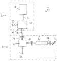
- the Figure 2 shows the drive train of the round baler 10 schematically.
- the crankshaft 80 of the internal combustion engine 74 is coupled to a transmission 82 which, on the one hand, drives a drive train to the drivable rear wheels 78 of the towing vehicle 50 (and possibly to the steerable front wheels 76), and on the other hand also drives a PTO output 84, which is driven by an articulated shaft 86 Moving elements of the round baler 10 drives.
- the propeller shaft 86 drives a transfer case 90 via a first clutch 88, which in turn drives one or more of the rollers 28, which in turn drive the conveying elements 22.
- An output of transfer case 90 is connected to roller 36 via a second clutch 92.
- the roller 36 can be coupled to the drives 54 and / or 62 via a third clutch 94.
- the clutch 88 could also be replaced or supplemented by a PTO clutch (not shown) of the towing vehicle 50, which takes over the function of the clutch 88.
- the controller 38 upon input by the operator via the input device 42, causes the first clutch 88 and the second clutch 92 to be closed.
- the third clutch 94 is opened.
- the conveying means 22, 22 'thus move and material (harvested material) entering through the inlet 26 is gradually formed into a bale 32 of continuously increasing diameter, while the towing vehicle 50 pulls the round baler 10 along a swath and the pickup 30 inwards promotes inlet 26.
- the control 38 Upon manual input by the operator into the input device 42 or when the control 38 detects that a predeterminable size of the bale 32 has been reached, the control 38 notifies the operator via the display device 40 that a wrapping process is now imminent and that he the towing vehicle 50 may stop. The stopping can also be carried out automatically by the controller 38 via the speed setting device 66.
- the controller 38 now causes the first clutch 88 to remain closed, the second clutch 92 to be opened and the third clutch 94 to be closed.
- one of the drives 54 or 62 is set in motion in order to convey the wrapping material from the supply 46 or 60 into the bale forming chamber 24, while the bale 32 continues to be driven by the conveying means 22, but no longer by the roller 36 of the conveying means 22 ' becomes.
- Mechanically actuated clutches can be selected by the operator which of the drives 54 or 62 is activated. In an advanced embodiment, this selection can be made via the input device 42 and the control 38, the corresponding couplings electromechanically or can control electrohydraulically to select the winding material.
- rollers 48 and 64 are driven via the roller 36 (which is separated from its drive train by the second clutch 92 from its drive train which drives it when the bale is formed) and which in turn is driven by friction through the bale 32, mechanically via the third clutch 94 and the drives 54 or 62.
- This ensures that the feed means is driven at exactly the circumferential speed of the bale 32 (or by a predetermined percentage slower), so that even if the bale 32 should slip relative to the conveying means 22, the wrapping material is not inserted faster than the bale 32 rotates. In this way, unwanted loop formation in the winding material is avoided and prevents the winding material from e.g. wraps around roller 36.
- the first and third couplings 88, 94 are separated and the bale 32 is ejected from the round baler 10 after opening the rear, pivotable housing half 20. A new bale 32 can then be produced.
- the round baler can also be designed as a fixed chamber press in which a number of rollers are distributed around the circumference of the bale formation chamber.
- One of these rollers then corresponds to the roller 36 of the embodiment shown here.
- the clutches 92, 94 need not be designed as disc clutches, as in the Figure 2 shown, but can be designed as belt couplings. The latter can also be mounted on the same side of the roller 36 and in particular can be actuated alternately by a single actuator.
Landscapes
- Life Sciences & Earth Sciences (AREA)
- Environmental Sciences (AREA)
- Engineering & Computer Science (AREA)
- Mechanical Engineering (AREA)
- Storage Of Harvested Produce (AREA)
Description
- Die Erfindung betrifft eine Rundballenpresse, umfassend:
- eine Ballenbildungskammer, um deren Umfang antreibbare Förderelemente verteilt sind, die mittels eines Antriebsstranges in Bewegung versetzbar sind, um in die Ballenbildungskammer eingeführtes Material zu einem Ballen zu formen, und
- Vorschubmittel, die eingerichtet sind, Wickelmaterial von einem Vorrat in Richtung auf die Ballenbildungskammer zu bewegen, um einen in der Ballenbildungskammer fertiggestellten Ballen zu umwickeln.
- Rundballenpressen sind üblicherweise mit Vorrichtungen zum Umwickeln des fertig gestellten Ballens ausgestattet, die durch einen Antrieb in Bewegung versetzt werden und ein Garn, ein Netz oder eine Folie abgeben, das oder die sich um den rotierenden Ballen legt und diesem umhüllt. Derartige Vorrichtungen sind nach der Fertigstellung des Ballens zu aktivieren, was im Stand der Technik auf Veranlassung des Bedieners mittels einer Eingabeeinrichtung erfolgt, nachdem ihm durch eine Anzeigeeinrichtung signalisiert wurde, dass die mittels eines geeigneten Sensors erfasste Ballengröße einen bestimmten Wert erreicht hat. Es wurde auch vorgeschlagen, den Antrieb der Anordnung zum Umwickeln des Ballens selbsttätig zu aktivieren, sobald der Sensor zur Erfassung der Ballengröße anzeigt, dass der gewünschte Ballendurchmesser demnächst erreicht wird (
DE 10 2009 002 439 A1 ). - Das Vorschieben des Wickelmaterials in Richtung auf den Ballenpressraum zu erfolgt durch Rollen, zwischen denen das Wickelmaterial hindurch geführt wird. Diese Rollen sind im Stand der Technik antriebsmäßig mit dem Antrieb der Ballenbildungsmittel gekoppelt, bei denen es sich um Riemen oder Walzen handelt, die um den Umfang der Ballenpresskammer verteilt sind. Die Rollen fördern das Wickelmaterial etwas langsamer als die Umfangsgeschwindigkeit des Ballens in die Ballenbildungskammer hinein, bis das Wickelmaterial durch den Ballen erfasst wird. Anschließend zieht der Ballen das Wickelmaterial vom Vorrat ab und ein Freilauf trennt die Rollen von ihren Antrieb.
- Solange die Geschwindigkeit des Ballens mit der Geschwindigkeit der Ballenbildungsmittel übereinstimmt, d.h. kein Schlupf auftritt, wird das Wickelmaterial problemlos vom Ballen mitgenommen. Sollte jedoch Schlupf zwischen dem Ballen und den Ballenbildungsmitteln auftreten, was beispielsweise bei feuchtem Erntegut wie Silage möglich ist, sodass die Umfangsgeschwindigkeit des Ballens kleiner ist als die der Ballenbildungsmittel, ist zwangsläufig auch die Vorschubgeschwindigkeit des Wickelmaterials größer als die Umfangsgeschwindigkeit des Ballens. Das führt zu Schlaufenbildungen im Wickelmaterial, nicht optimaler Umwicklung des Ballens und im ungünstigsten Fall dazu, dass sich das Wickelmaterial um eine Walze des Ballenpressraums wickelt und durch den Bediener entfernt werden muss.
- Die vorliegende Erfindung hat sich zur Aufgabe gesetzt, das beschriebene Problem zu vermeiden oder zumindest zu verbessern.
- Die vorliegende Erfindung wird durch die Ansprüche definiert.
- Eine Rundballenpresse umfasst eine Ballenbildungskammer, um deren Umfang antreibbare Förderelemente verteilt sind, die mittels eines Antriebsstranges in Bewegung versetzbar sind, um in die Ballenbildungskammer eingeführtes Material zu einem Ballen zu formen, und Vorschubmittel, die eingerichtet sind, Wickelmaterial von einem Vorrat in Richtung auf die Ballenbildungskammer zu bewegen, um einen in der Ballenbildungskammer fertiggestellten Ballen zu umwickeln. Ein Teil der Förderelemente ist während des Wickelvorgangs vom Antriebsstrang trennbar und mit den Vorschubmitteln koppelbar.
- Auf diese Weise erreicht man, dass der besagte Teil der Förderelemente während des Wickelvorgangs durch den zu umwickelnden Ballen angetrieben wird und die Vorschubmittel mit einer von der jeweiligen Umfangsgeschwindigkeit des Ballens abhängigen Geschwindigkeit antreibt. Somit hängt die Vorschubgeschwindigkeit des Wickelmaterials direkt von der Umfangsgeschwindigkeit des Ballens ab und die im Stand der Technik vorliegenden Nachteile werden vermieden.
- In den Zeichnungen ist ein nachfolgend näher beschriebenes Ausführungsbeispiel der Erfindung dargestellt, wobei die Bezugszeichen nicht zur einschränkenden Auslegung herangezogen werden sollen. Es zeigt:
- Fig. 1
- eine Rundballenpresse mit einer Vorrichtung zum Umwickeln eines Ballens und
einem Zugfahrzeug in Seitenansicht und in schematischer Darstellung, und - Fig. 2
- ein Schema des Antriebs der Rundballenpresse der
Figur 1 . - Die
Figur 1 zeigt eine Rundballenpresse 10 mit einem Gehäuse 12, das mittels einer Deichsel 14 an einer Kupplungsöse eines Zugfahrzeugs 50 in Form eines Ackerschleppers angehängt werden kann, um bezüglich derFigur 1 nach rechts in einer Fahrtrichtung über ein Feld gezogen zu werden, und sich auf Rädern 16 abstützt. Das Gehäuse 12 setzt sich aus einer vorderen, starren Gehäusehälfte 18 und einer rückwärtigen, schwenkbaren Gehäusehälfte 20 zusammen, die in einem oben liegenden Gelenk 19 schwenkbar miteinander verbunden sind. Das Gehäuse 12 trägt eine Vielzahl von Walzen 28. Über die Walzen 28 verlaufen mehrere nebeneinander angeordnete endlose Förderelemente 22, die zusammen mit Seitenwänden des Gehäuses 12 eine Ballenbildungskammer 24 größtenteils umgeben. In diesem Ausführungsbeispiel sind die Förderelemente 22 größtenteils als Riemen ausgebildet, wobei jedoch ein Förderelement 22' als Walze 36 gestaltet ist. In dem unteren Bereich der Ballenbildungskammer 24 ist ein Einlass 26 vorgesehen, der rückwärtig von einer Walze 28 begrenzt wird und von einem Aufnehmer 30 aufgenommenes Gut in die Ballenbildungskammer 24 eintreten lässt. Die Walze 36 befindet sich oberhalb des Einlasses 26 und davor. - Die Rundballenpresse 10 umfasst mehrere seitlich nebeneinander angeordnete Förderelemente 22. Sie werden beim Erntebetrieb in Bewegung versetzt und umschließen einen sich in der Ballenbildungskammer 24 bildenden Ballen 32 nach vorn, oben und hinten. Der Aufbau und die Funktion einer derartigen Rundballenpresse sind an sich bekannt. Es wird auf die Offenbarung der
DE 101 53 540 A verwiesen, deren Inhalt durch Verweis mit in die vorliegenden Unterlagen aufgenommen wird. Mit den Bezugszeichen 32, 32' und 32" sind Ballen anwachsenden Durchmessers gekennzeichnet. - Am rückwärtigen, oberen Ende der rückwärtigen, schwenkbaren Gehäusehälfte 20 ist ein Sensor 34 befestigt. Der Sensor 34 ist ein Ultraschallentfernungsmesser, der auf einer Laufzeitmessung beruht und erfasst den Abstand zwischen ihrer Unterseite und den benachbarten Fördermitteln 22, die unmittelbar am äußeren Umfang des Ballens 32 anliegen. Der Sensor 34 stellt auf diese Weise eine Information über den Durchmesser des Ballens 32 bereit.
- Die Rundballenpresse 10 umfasst weiterhin einen ersten Wickelmaterialspender 44, der an der Rückseite der rückwärtigen, schwenkbaren Gehäusehälfte 20 angeordnet ist. Der Wickelmaterialspender 44 umfasst einen Vorrat 46 an Wickelmaterial, das aus einem aufgerollten Netz oder einer Folie besteht, deren vorderes, abgewickeltes Ende zwischen Paaren von als Vorschubmittel dienenden Rollen 48 hindurchgeführt ist. Die Rollen 48 sind durch einen Antrieb 54 in Drehung versetzbar, so dass das vordere Ende des Wickelmaterials bei aktiviertem Antrieb 54 durch die Fördermittel 22 mitgezogen wird, in die Ballenbildungskammer 24 gelangt und dort den Ballen 32 umhüllt. Zwischen dem Antrieb 54 und den Rollen 48 ist ein Freilauf (nicht gezeigt) angeordnet, damit der Ballen 32 das Wickelmaterial beim Umwickeln vom Vorrat 46 abziehen kann, ohne den Antrieb 54 mitzudrehen. Außerdem umfasst der erste Wickelmaterialspender 44 eine Trenneinrichtung 56, um nach dem Wickelvorgang das Wickelmaterial abzuschneiden.
- Ein zweiter Wickelmaterialspender 58 befindet sich an der Vorderseite der Rundballenpresse 10 und umfasst einen Vorrat 60 an Wickelmaterial, das aus Garn besteht. Der zweite Wickelmaterialspender 58 umfasst ebenfalls ein Paar von als Vorschubmittel dienenden Rollen 64, die mittels eines Antriebs 62 antreibbar sind, um das vordere Ende des Wickelmaterials in die Ballenbildungskammer 24 einzuführen, so dass es dort durch den Ballen 32 mitgenommen wird und diesen umhüllt. Das Wickelmaterial wird sukzessive über die Breite des Ballens 32 geführt, indem der ganze Wickelmaterialspender 58 oder eine Auslassöffnung kontinuierlich seitlich bewegt wird. Zwischen dem Antrieb 62 und den Rollen 64 ist ein Freilauf (nicht gezeigt) angeordnet, damit der Ballen 32 das Wickelmaterial beim Umwickeln vom Vorrat 60 abziehen kann, ohne den Antrieb 62 mitzudrehen. Außerdem umfasst der erste Wickelmaterialspender 44 eine Trenneinrichtung (nicht gezeigt), um nach dem Wickelvorgang das Wickelmaterial abzuschneiden.
- Über eine Busleitung ist der Sensor 34 mit einer Steuerung 38 verbunden, die wiederum eine in der Fahrerkabine 52 des Zugfahrzeugs 50 angeordnete Anzeigeeinrichtung 40 ansteuert und Instruktionen von einer ebenfalls dort angeordneten Eingabeeinrichtung 42 erhält. Die Steuerung 38 ist außerdem mit Aktoren zur Betätigung von Kupplungen 88, 92 und 94 (vgl.
Figur 2 ), einer Geschwindigkeitsvorgabeeinrichtung (Motor- und Getriebesteuerung) 66 des Zugfahrzeugs 50, einem Geschwindigkeitssensor 68 in Form eines Drehzahlsensors zur Erfassung der Umdrehungszahl der Räder 16, einem Durchsatzsensor 70, der an der Unterseite der Deichsel 14 montiert ist und das von der Pickup 30 aufzunehmende Schwad optisch oder mit Ultraschallwellen abtastet, um sein Volumen festzustellen, und einer Positionsbestimmungseinrichtung 72 gekoppelt. Die Steuerung 38 kann insbesondere in der inDE 10 2009 002 439 A1 , deren Offenbarung durch Verweis mit in die vorliegenden Unterlagen aufgenommen wird, beschriebenen Weise vorgehen, um zu erkennen, wann es an der Zeit ist, einen Ballen zu umwickeln. - Die
Figur 2 zeigt den Antriebsstrang der Rundballenpresse 10 schematisch. Die Kurbelwelle 80 des Verbrennungsmotors 74 ist mit einem Getriebe 82 gekoppelt, das einerseits einen Antriebsstrang zu den antreibbaren Hinterrädern 78 des Zugfahrzeugs 50 (und ggf. zu den lenkbaren Vorderrädern 76) antreibt, andererseits auch einen Zapfwellenausgang 84 antreibt, der durch eine Gelenkwelle 86 die beweglichen Elemente der Rundballenpresse 10 antreibt. Seitens der Rundballenpresse 10 treibt die Gelenkwelle 86 über eine erste Kupplung 88 ein Verteilergetriebe 90 an, das wiederum eine oder mehrere der Walzen 28 antreibt, die wiederum die Förderelemente 22 antreiben. Ein Ausgang des Verteilergetriebes 90 ist über eine zweite Kupplung 92 mit der Walze 36 verbunden. Die Walze 36 ist über eine dritte Kupplung 94 mit den Antrieben 54 und/oder 62 koppelbar. Die Kupplung 88 könnte auch durch eine Zapfwellenkupplung (nicht gezeigt) des Zugfahrzeugs 50 ersetzt oder ergänzt werden, welche die Funktion der Kupplung 88 übernimmt. - Im Folgenden wird nun der Betrieb der Rundballenpresse 10 beschrieben.
- Im normalen Ballenbildungsbetrieb veranlasst die Steuerung 38 auf eine Eingabe des Bedieners über die Eingabeeinrichtung 42 hin, dass die erste Kupplung 88 und die zweite Kupplung 92 geschlossen sind. Die dritte Kupplung 94 ist geöffnet. Die Fördermittel 22, 22' bewegen sich somit und durch den Einlass 26 einlaufendes Material (Erntegut) wird nach und nach zu einem Ballen 32 kontinuierlich anwachsenden Durchmessers geformt, während das Zugfahrzeug 50 die Rundballenpresse 10 entlang eines Schwads zieht und der Aufnehmer 30 das Erntegut in den Einlass 26 fördert.
- Auf eine manuelle Eingabe des Bedieners in die Eingabeeinrichtung 42 oder wenn die Steuerung 38 erkennt, dass eine vorgebbare Größe des Ballens 32 erreicht ist, weist die Steuerung 38 den Bediener über die Anzeigeeinrichtung 40 darauf hin, dass nun ein Wickelvorgang bevorsteht und er das Zugfahrzeug 50 anhalten möge. Das Anhalten kann auch durch die Steuerung 38 selbsttätig über die Geschwindigkeitsvorgabeeinrichtung 66 erfolgen. Die Steuerung 38 veranlasst nun, dass die erste Kupplung 88 weiterhin geschlossen bleibt, die zweite Kupplung 92 geöffnet wird und die dritte Kupplung 94 geschlossen wird. Dadurch wird einer der Antriebe 54 oder 62 in Bewegung versetzt, um das Wickelmaterial vom Vorrat 46 oder 60 in die Ballenbildungskammer 24 hinein zu fördern, während der Ballen 32 weiterhin durch die Fördermittel 22, nicht aber mehr durch die Walze 36 der Fördermittel 22' angetrieben wird. Durch in der
Figur 2 nicht gezeigte, mechanisch betätigte Kupplungen kann der Bediener auswählen, welcher der Antriebe 54 oder 62 aktiviert wird. Bei einer fortgeschrittenen Ausführungsform kann diese Auswahl über die Eingabeeinrichtung 42 und die Steuerung 38 erfolgen, die entsprechende Kupplungen elektromechanisch oder elektrohydraulisch kontrollieren kann, um das Wickelmaterial auszuwählen. - Der Antrieb der Walzen 48 bzw. 64 erfolgt nach alledem über die (von ihrem durch die zweite Kupplung 92 von ihrem sie bei der Ballenbildung antreibenden Antriebsstrang getrennte) Walze 36, die ihrerseits durch Reibung durch den Ballen 32 angetrieben wird, mechanisch über die dritte Kupplung 94 und die Antriebe 54 oder 62. Dadurch wird sichergestellt, dass das Vorschubmittel mit genau der Umfangsgeschwindigkeit des Ballens 32 (oder um einen festgelegten Prozentsatz langsamer) angetrieben wird, sodass auch dann, wenn der Ballen 32 gegenüber den Fördermitteln 22 rutschen sollte, das Wickelmaterial nicht schneller eingeführt wird als der Ballen 32 dreht. Auf diese Weise werden unerwünschte Schlaufenbildungen im Wickelmaterial vermieden und verhindert, dass sich das Wickelmaterial z.B. um die Walze 36 wickelt.
- Nach dem vollständigen Umwickeln des Ballens 32 werden die erste und dritte Kupplung 88, 94 getrennt und der Ballen 32 nach Öffnen der rückwärtigen, schwenkbaren Gehäusehälfte 20 aus der Rundballenpresse 10 ausgeworfen. Anschließend kann ein neuer Ballen 32 erzeugt werden.
- Anzumerken bleibt, dass die Rundballenpresse bei einer anderen Ausführungsform auch als Festkammerpresse ausgeführt sein kann, bei der eine Anzahl an Walzen um den Umfang der Ballenbildungskammer verteilt ist. Eine dieser Walzen entspricht dann der Walze 36 der hier gezeigten Ausführungsform. Es wäre auch denkbar, anstelle der rückwärtigen, schwenkbaren Gehäusehälfte 20 nur einen Träger nach oben zu schwenken, der einige der Walzen 28 trägt, vgl.
EP 1 795 065 A1 und dort zitierte Referenzen, bzw. einige direkt mit dem Erntegut zusammenwirkende Walzen an einem beweglichen Träger anzubringen, vgl.DE 10 2009 002 585 A1 . Die Kupplungen 92, 94 müssen nicht als Scheibenkupplungen ausgeführt sein, wie in derFigur 2 gezeigt, sondern können als Riemenkupplungen gestaltet werden. Letztere können auch auf derselben Seite der Walze 36 angebracht sein und insbesondere durch einen einzigen Aktor wechselweise betätigt werden.
Claims (4)
- Rundballenpresse (10), umfassend:eine Ballenbildungskammer (24), um deren Umfang antreibbare Förderelemente (22, 22') verteilt sind, die mittels eines Antriebsstranges in Bewegung versetzbar sind, um in den Ballenpressraum (24) eingeführtes Material zu einem Ballen (32) zu formen, undVorschubmittel, die eingerichtet sind, Wickelmaterial von einem Vorrat (46, 60) in Richtung auf die Ballenbildungskammer (24) zu bewegen, um einen in der Ballenbildungskammer (24) fertiggestellten Ballen (32) zu umwickeln,dadurch gekennzeichnet, dass ein Teil (22') der Förderelemente (22, 22') durch eine Kupplung (92) trennbar mit dem Antriebsstrang verbunden und durch eine andere Kupplung (94) antriebsmäßig mit den Vorschubmitteln koppelbar ist und eine Steuerung (38) betreibbar ist, die Kupplungen (92, 94) derart anzusteuern, dass der besagte Teil der Förderelemente (22') während des Wickelvorgangs vom Antriebsstrang getrennt und mit den Vorschubmitteln gekoppelt ist, sodass der besagte Teil (22') der Förderelemente (22, 22') während des Wickelvorgangs durch den zu umwickelnden Ballen (32) angetrieben wird und die Vorschubmittel mit einer von der jeweiligen Umfangsgeschwindigkeit des Ballens (32) abhängigen Geschwindigkeit antreibt.
- Rundballenpresse (10) nach Anspruch 1, wobei der Teil (22') der Förderelemente (22, 22') eine Walze (36) ist.
- Rundballenpresse (10) nach Anspruch 1 oder 2, wobei das Wickelmaterial ein Netz, Garn oder Folie ist.
- Verfahren zum Betreiben einer Rundballenpresse (10), die eine Ballenbildungskammer (24), um deren Umfang antreibbare Förderelemente (22, 22') verteilt sind, die mittels eines Antriebsstranges in Bewegung versetzbar sind, um in den Ballenpressraum (24) eingeführtes Material zu einem Ballen (32) zu formen, und Vorschubmittel umfasst, die eingerichtet sind, Wickelmaterial von einem Vorrat (46, 60) in Richtung auf die Ballenbildungskammer (24) zu bewegen, um einen in der Ballenbildungskammer (24) fertiggestellten Ballen (32) zu umwickeln, dadurch gekennzeichnet, dass ein Teil (22') der Förderelemente (22, 22') während des Wickelvorgangs vom Antriebsstrang getrennt und mit den Vorschubmitteln gekoppelt wird, sodass der besagte Teil (22') der Förderelemente (22, 22') durch eine Kupplung (92) trennbar mit dem Antriebsstrang verbunden und durch eine andere Kupplung (94) antriebsmäßig mit den Vorschubmitteln koppelbar ist und eine Steuerung (38) betreibbar ist, die Kupplungen (92, 94) derart anzusteuern, dass der besagte Teil der Förderelemente (22') während des Wickelvorgangs durch den zu umwickelnden Ballen (32) angetrieben wird und die Vorschubmittel mit einer von der jeweiligen Umfangsgeschwindigkeit des Ballens (32) abhängigen Geschwindigkeit antreibt.
Applications Claiming Priority (1)
| Application Number | Priority Date | Filing Date | Title |
|---|---|---|---|
| DE102015211000.1A DE102015211000A1 (de) | 2015-06-16 | 2015-06-16 | Rundballenpresse mit Mitteln zum Umwickeln eines Ballens |
Publications (2)
| Publication Number | Publication Date |
|---|---|
| EP3106018A1 EP3106018A1 (de) | 2016-12-21 |
| EP3106018B1 true EP3106018B1 (de) | 2020-02-19 |
Family
ID=56087186
Family Applications (1)
| Application Number | Title | Priority Date | Filing Date |
|---|---|---|---|
| EP16171878.8A Active EP3106018B1 (de) | 2015-06-16 | 2016-05-30 | Rundballenpresse mit mitteln zum umwickeln eines ballens |
Country Status (3)
| Country | Link |
|---|---|
| US (1) | US20160374271A1 (de) |
| EP (1) | EP3106018B1 (de) |
| DE (1) | DE102015211000A1 (de) |
Families Citing this family (3)
| Publication number | Priority date | Publication date | Assignee | Title |
|---|---|---|---|---|
| BE1023393B1 (nl) * | 2015-07-15 | 2017-03-01 | Cnh Industrial Belgium Nv | Balenpers voor de landbouw met een achterklep in twee delen en een werkwijze voor het uitvoeren van een ontlaadsequentie |
| CN109922656A (zh) | 2016-08-31 | 2019-06-21 | 维米尔制造公司 | 连续圆形打捆机和形成圆形草捆的改进方法 |
| JP7157713B2 (ja) * | 2019-07-30 | 2022-10-20 | 株式会社クボタ | 走行車両および作業車両 |
Family Cites Families (17)
| Publication number | Priority date | Publication date | Assignee | Title |
|---|---|---|---|---|
| US4790125A (en) * | 1987-05-01 | 1988-12-13 | New Holland Inc. | Feed rollers for round baler net dispenser |
| US5488883A (en) * | 1992-12-18 | 1996-02-06 | Vermeer Manufacturing Company | Direct drive system for a baler |
| US5551218A (en) * | 1994-09-19 | 1996-09-03 | Gehl Company | Round baler monitoring and control system |
| US6247291B1 (en) * | 1999-07-21 | 2001-06-19 | New Holland North America, Inc. | Storage apparatus for round baler wrapping material |
| DE10153540A1 (de) | 2001-10-30 | 2003-06-26 | Deere & Co | Rundballenpresse |
| DE10309657A1 (de) * | 2003-03-06 | 2004-09-30 | Deere & Company, Moline | Vorrichtung zum Umhüllen eines Ballens mit einer Hüllbahn und Ballenpresse |
| DE102005059127A1 (de) | 2005-12-10 | 2007-06-28 | Deere & Company, Moline | Ballenpresse mit einer Feuchtemesseinrichtung |
| US7937923B2 (en) * | 2007-10-25 | 2011-05-10 | Deere & Company | Tractor and round baler combination with automatic baling and automatic rear door opening |
| EP2113165B1 (de) * | 2008-04-30 | 2011-08-24 | Deere & Company | Bahnwicklungsvorrichtung |
| DE102009002439A1 (de) | 2008-11-19 | 2010-05-20 | Deere & Company, Moline | Anordnung und Verfahren zum Umwickeln eines Ballens |
| DE102009002585B4 (de) | 2009-04-23 | 2018-08-02 | Deere & Company | Rundballenpresse |
| US8581554B2 (en) * | 2009-07-10 | 2013-11-12 | Schneider Electric It Corporation | Battery charging method and apparatus |
| US8429881B2 (en) * | 2009-09-18 | 2013-04-30 | Agco Corporation | Baler starter roll |
| PL2382858T3 (pl) * | 2010-04-29 | 2013-04-30 | Deere & Co | Prasa zwijająca z napędzaną elektrycznie rolką |
| DE102011003727A1 (de) * | 2011-02-07 | 2012-08-09 | Deere & Company | Rundballenpresse mit seitlichen Führungen für den Pressriemen |
| US20140326149A1 (en) * | 2011-12-15 | 2014-11-06 | Agco Corporation | Crop contacting roller driven by bale forming belts |
| DE102014200449A1 (de) * | 2014-01-13 | 2015-07-16 | Deere & Company | Landwirtschaftliche Rundballenpresse und Verfahren |
-
2015
- 2015-06-16 DE DE102015211000.1A patent/DE102015211000A1/de not_active Withdrawn
-
2016
- 2016-05-30 EP EP16171878.8A patent/EP3106018B1/de active Active
- 2016-06-14 US US15/181,574 patent/US20160374271A1/en not_active Abandoned
Non-Patent Citations (1)
| Title |
|---|
| None * |
Also Published As
| Publication number | Publication date |
|---|---|
| EP3106018A1 (de) | 2016-12-21 |
| US20160374271A1 (en) | 2016-12-29 |
| DE102015211000A1 (de) | 2016-12-22 |
Similar Documents
| Publication | Publication Date | Title |
|---|---|---|
| DE69709981T2 (de) | Rundballenpresse | |
| DE60312097T2 (de) | Rundballenpresse | |
| DE60218400T2 (de) | Rundballenpresse | |
| DE10312897B4 (de) | Vorrichtung zum Umhüllen eines Ballens mit einer Hüllbahn und Ballenpresse | |
| EP2243349B1 (de) | Rundballenpresse | |
| DE102009002439A1 (de) | Anordnung und Verfahren zum Umwickeln eines Ballens | |
| DE212010000174U1 (de) | Ballenpresse zum Formen von Ballen ausFeldfrüchten | |
| EP0102530B1 (de) | Verfahren zum Beseitigen von Überlastungen von Erntegutklumpen oder dgl. bei einer Anordnung zum Herstellen von zylindrischen Ballen aus Erntegut | |
| DE2538164C3 (de) | Rundballenpresse für Heu und anderes faseriges Erntegut mit einer Spannvorrichtung für die den Balten formenden umlaufbaren Bänder | |
| DE3301420C2 (de) | ||
| DE60219375T2 (de) | Presse mit einer Reversiereinrichtung für den Rotor | |
| EP3106018A1 (de) | Rundballenpresse mit mitteln zum umwickeln eines ballens | |
| EP0535532A2 (de) | Verfahren zum Binden eines Ballens und Vorrichtung hierfür | |
| EP1864567B1 (de) | Gutaufnehmer | |
| DE2530320C3 (de) | Bindevorrichtung für Wickelballenpressen | |
| DE69801615T2 (de) | Sicherheitsvorrichtung für eine Nadelauslöseeinrichtung | |
| DE102007031211B4 (de) | Ballenpresse | |
| EP3106024A1 (de) | Rundballenpresse mit mitteln zur führung eines pressriemens | |
| EP2803259B1 (de) | Kombination aus einem Zugfahrzeug und einer landwirtschaftlichen Ballenpresse | |
| EP2042027A1 (de) | Rundballenpresse | |
| EP1454521B2 (de) | Vorrichtung zum Umhüllen eines Ballens mit einer Hüllbahn und Ballenpresse | |
| EP2556743B1 (de) | Landwirtschaftliche Rundballenpresse | |
| EP3300585B1 (de) | Rundballenpresse zum aufnehmen und pressen von landwirtschaftlichem erntegut | |
| EP4186350B1 (de) | Verfahren zum betreiben einer rundballenpresse | |
| EP3106019A1 (de) | Rundballenpresse und zuführwalze für wickelmaterial |
Legal Events
| Date | Code | Title | Description |
|---|---|---|---|
| PUAI | Public reference made under article 153(3) epc to a published international application that has entered the european phase |
Free format text: ORIGINAL CODE: 0009012 |
|
| STAA | Information on the status of an ep patent application or granted ep patent |
Free format text: STATUS: THE APPLICATION HAS BEEN PUBLISHED |
|
| AK | Designated contracting states |
Kind code of ref document: A1 Designated state(s): AL AT BE BG CH CY CZ DE DK EE ES FI FR GB GR HR HU IE IS IT LI LT LU LV MC MK MT NL NO PL PT RO RS SE SI SK SM TR |
|
| AX | Request for extension of the european patent |
Extension state: BA ME |
|
| STAA | Information on the status of an ep patent application or granted ep patent |
Free format text: STATUS: REQUEST FOR EXAMINATION WAS MADE |
|
| 17P | Request for examination filed |
Effective date: 20170621 |
|
| RBV | Designated contracting states (corrected) |
Designated state(s): AL AT BE BG CH CY CZ DE DK EE ES FI FR GB GR HR HU IE IS IT LI LT LU LV MC MK MT NL NO PL PT RO RS SE SI SK SM TR |
|
| RIC1 | Information provided on ipc code assigned before grant |
Ipc: A01F 15/07 20060101AFI20190807BHEP |
|
| GRAP | Despatch of communication of intention to grant a patent |
Free format text: ORIGINAL CODE: EPIDOSNIGR1 |
|
| STAA | Information on the status of an ep patent application or granted ep patent |
Free format text: STATUS: GRANT OF PATENT IS INTENDED |
|
| INTG | Intention to grant announced |
Effective date: 20190920 |
|
| GRAS | Grant fee paid |
Free format text: ORIGINAL CODE: EPIDOSNIGR3 |
|
| GRAA | (expected) grant |
Free format text: ORIGINAL CODE: 0009210 |
|
| STAA | Information on the status of an ep patent application or granted ep patent |
Free format text: STATUS: THE PATENT HAS BEEN GRANTED |
|
| AK | Designated contracting states |
Kind code of ref document: B1 Designated state(s): AL AT BE BG CH CY CZ DE DK EE ES FI FR GB GR HR HU IE IS IT LI LT LU LV MC MK MT NL NO PL PT RO RS SE SI SK SM TR |
|
| REG | Reference to a national code |
Ref country code: CH Ref legal event code: EP |
|
| REG | Reference to a national code |
Ref country code: DE Ref legal event code: R096 Ref document number: 502016008766 Country of ref document: DE |
|
| REG | Reference to a national code |
Ref country code: AT Ref legal event code: REF Ref document number: 1233898 Country of ref document: AT Kind code of ref document: T Effective date: 20200315 |
|
| REG | Reference to a national code |
Ref country code: IE Ref legal event code: FG4D Free format text: LANGUAGE OF EP DOCUMENT: GERMAN |
|
| REG | Reference to a national code |
Ref country code: NL Ref legal event code: MP Effective date: 20200219 |
|
| PG25 | Lapsed in a contracting state [announced via postgrant information from national office to epo] |
Ref country code: FI Free format text: LAPSE BECAUSE OF FAILURE TO SUBMIT A TRANSLATION OF THE DESCRIPTION OR TO PAY THE FEE WITHIN THE PRESCRIBED TIME-LIMIT Effective date: 20200219 Ref country code: RS Free format text: LAPSE BECAUSE OF FAILURE TO SUBMIT A TRANSLATION OF THE DESCRIPTION OR TO PAY THE FEE WITHIN THE PRESCRIBED TIME-LIMIT Effective date: 20200219 Ref country code: NO Free format text: LAPSE BECAUSE OF FAILURE TO SUBMIT A TRANSLATION OF THE DESCRIPTION OR TO PAY THE FEE WITHIN THE PRESCRIBED TIME-LIMIT Effective date: 20200519 |
|
| REG | Reference to a national code |
Ref country code: LT Ref legal event code: MG4D |
|
| PG25 | Lapsed in a contracting state [announced via postgrant information from national office to epo] |
Ref country code: IS Free format text: LAPSE BECAUSE OF FAILURE TO SUBMIT A TRANSLATION OF THE DESCRIPTION OR TO PAY THE FEE WITHIN THE PRESCRIBED TIME-LIMIT Effective date: 20200619 Ref country code: GR Free format text: LAPSE BECAUSE OF FAILURE TO SUBMIT A TRANSLATION OF THE DESCRIPTION OR TO PAY THE FEE WITHIN THE PRESCRIBED TIME-LIMIT Effective date: 20200520 Ref country code: BG Free format text: LAPSE BECAUSE OF FAILURE TO SUBMIT A TRANSLATION OF THE DESCRIPTION OR TO PAY THE FEE WITHIN THE PRESCRIBED TIME-LIMIT Effective date: 20200519 Ref country code: LV Free format text: LAPSE BECAUSE OF FAILURE TO SUBMIT A TRANSLATION OF THE DESCRIPTION OR TO PAY THE FEE WITHIN THE PRESCRIBED TIME-LIMIT Effective date: 20200219 Ref country code: SE Free format text: LAPSE BECAUSE OF FAILURE TO SUBMIT A TRANSLATION OF THE DESCRIPTION OR TO PAY THE FEE WITHIN THE PRESCRIBED TIME-LIMIT Effective date: 20200219 Ref country code: HR Free format text: LAPSE BECAUSE OF FAILURE TO SUBMIT A TRANSLATION OF THE DESCRIPTION OR TO PAY THE FEE WITHIN THE PRESCRIBED TIME-LIMIT Effective date: 20200219 |
|
| PG25 | Lapsed in a contracting state [announced via postgrant information from national office to epo] |
Ref country code: NL Free format text: LAPSE BECAUSE OF FAILURE TO SUBMIT A TRANSLATION OF THE DESCRIPTION OR TO PAY THE FEE WITHIN THE PRESCRIBED TIME-LIMIT Effective date: 20200219 |
|
| PG25 | Lapsed in a contracting state [announced via postgrant information from national office to epo] |
Ref country code: ES Free format text: LAPSE BECAUSE OF FAILURE TO SUBMIT A TRANSLATION OF THE DESCRIPTION OR TO PAY THE FEE WITHIN THE PRESCRIBED TIME-LIMIT Effective date: 20200219 Ref country code: DK Free format text: LAPSE BECAUSE OF FAILURE TO SUBMIT A TRANSLATION OF THE DESCRIPTION OR TO PAY THE FEE WITHIN THE PRESCRIBED TIME-LIMIT Effective date: 20200219 Ref country code: SK Free format text: LAPSE BECAUSE OF FAILURE TO SUBMIT A TRANSLATION OF THE DESCRIPTION OR TO PAY THE FEE WITHIN THE PRESCRIBED TIME-LIMIT Effective date: 20200219 Ref country code: PT Free format text: LAPSE BECAUSE OF FAILURE TO SUBMIT A TRANSLATION OF THE DESCRIPTION OR TO PAY THE FEE WITHIN THE PRESCRIBED TIME-LIMIT Effective date: 20200712 Ref country code: SM Free format text: LAPSE BECAUSE OF FAILURE TO SUBMIT A TRANSLATION OF THE DESCRIPTION OR TO PAY THE FEE WITHIN THE PRESCRIBED TIME-LIMIT Effective date: 20200219 Ref country code: LT Free format text: LAPSE BECAUSE OF FAILURE TO SUBMIT A TRANSLATION OF THE DESCRIPTION OR TO PAY THE FEE WITHIN THE PRESCRIBED TIME-LIMIT Effective date: 20200219 Ref country code: EE Free format text: LAPSE BECAUSE OF FAILURE TO SUBMIT A TRANSLATION OF THE DESCRIPTION OR TO PAY THE FEE WITHIN THE PRESCRIBED TIME-LIMIT Effective date: 20200219 Ref country code: RO Free format text: LAPSE BECAUSE OF FAILURE TO SUBMIT A TRANSLATION OF THE DESCRIPTION OR TO PAY THE FEE WITHIN THE PRESCRIBED TIME-LIMIT Effective date: 20200219 Ref country code: CZ Free format text: LAPSE BECAUSE OF FAILURE TO SUBMIT A TRANSLATION OF THE DESCRIPTION OR TO PAY THE FEE WITHIN THE PRESCRIBED TIME-LIMIT Effective date: 20200219 |
|
| REG | Reference to a national code |
Ref country code: DE Ref legal event code: R097 Ref document number: 502016008766 Country of ref document: DE |
|
| PLBE | No opposition filed within time limit |
Free format text: ORIGINAL CODE: 0009261 |
|
| STAA | Information on the status of an ep patent application or granted ep patent |
Free format text: STATUS: NO OPPOSITION FILED WITHIN TIME LIMIT |
|
| 26N | No opposition filed |
Effective date: 20201120 |
|
| PG25 | Lapsed in a contracting state [announced via postgrant information from national office to epo] |
Ref country code: LI Free format text: LAPSE BECAUSE OF NON-PAYMENT OF DUE FEES Effective date: 20200531 Ref country code: IT Free format text: LAPSE BECAUSE OF FAILURE TO SUBMIT A TRANSLATION OF THE DESCRIPTION OR TO PAY THE FEE WITHIN THE PRESCRIBED TIME-LIMIT Effective date: 20200219 Ref country code: CH Free format text: LAPSE BECAUSE OF NON-PAYMENT OF DUE FEES Effective date: 20200531 Ref country code: MC Free format text: LAPSE BECAUSE OF FAILURE TO SUBMIT A TRANSLATION OF THE DESCRIPTION OR TO PAY THE FEE WITHIN THE PRESCRIBED TIME-LIMIT Effective date: 20200219 |
|
| PG25 | Lapsed in a contracting state [announced via postgrant information from national office to epo] |
Ref country code: SI Free format text: LAPSE BECAUSE OF FAILURE TO SUBMIT A TRANSLATION OF THE DESCRIPTION OR TO PAY THE FEE WITHIN THE PRESCRIBED TIME-LIMIT Effective date: 20200219 Ref country code: PL Free format text: LAPSE BECAUSE OF FAILURE TO SUBMIT A TRANSLATION OF THE DESCRIPTION OR TO PAY THE FEE WITHIN THE PRESCRIBED TIME-LIMIT Effective date: 20200219 |
|
| REG | Reference to a national code |
Ref country code: BE Ref legal event code: MM Effective date: 20200531 |
|
| GBPC | Gb: european patent ceased through non-payment of renewal fee |
Effective date: 20200530 |
|
| PG25 | Lapsed in a contracting state [announced via postgrant information from national office to epo] |
Ref country code: LU Free format text: LAPSE BECAUSE OF NON-PAYMENT OF DUE FEES Effective date: 20200530 |
|
| PG25 | Lapsed in a contracting state [announced via postgrant information from national office to epo] |
Ref country code: GB Free format text: LAPSE BECAUSE OF NON-PAYMENT OF DUE FEES Effective date: 20200530 Ref country code: IE Free format text: LAPSE BECAUSE OF NON-PAYMENT OF DUE FEES Effective date: 20200530 |
|
| PG25 | Lapsed in a contracting state [announced via postgrant information from national office to epo] |
Ref country code: BE Free format text: LAPSE BECAUSE OF NON-PAYMENT OF DUE FEES Effective date: 20200531 |
|
| PG25 | Lapsed in a contracting state [announced via postgrant information from national office to epo] |
Ref country code: TR Free format text: LAPSE BECAUSE OF FAILURE TO SUBMIT A TRANSLATION OF THE DESCRIPTION OR TO PAY THE FEE WITHIN THE PRESCRIBED TIME-LIMIT Effective date: 20200219 Ref country code: MT Free format text: LAPSE BECAUSE OF FAILURE TO SUBMIT A TRANSLATION OF THE DESCRIPTION OR TO PAY THE FEE WITHIN THE PRESCRIBED TIME-LIMIT Effective date: 20200219 Ref country code: CY Free format text: LAPSE BECAUSE OF FAILURE TO SUBMIT A TRANSLATION OF THE DESCRIPTION OR TO PAY THE FEE WITHIN THE PRESCRIBED TIME-LIMIT Effective date: 20200219 |
|
| PG25 | Lapsed in a contracting state [announced via postgrant information from national office to epo] |
Ref country code: MK Free format text: LAPSE BECAUSE OF FAILURE TO SUBMIT A TRANSLATION OF THE DESCRIPTION OR TO PAY THE FEE WITHIN THE PRESCRIBED TIME-LIMIT Effective date: 20200219 Ref country code: AL Free format text: LAPSE BECAUSE OF FAILURE TO SUBMIT A TRANSLATION OF THE DESCRIPTION OR TO PAY THE FEE WITHIN THE PRESCRIBED TIME-LIMIT Effective date: 20200219 |
|
| REG | Reference to a national code |
Ref country code: AT Ref legal event code: MM01 Ref document number: 1233898 Country of ref document: AT Kind code of ref document: T Effective date: 20210530 |
|
| PG25 | Lapsed in a contracting state [announced via postgrant information from national office to epo] |
Ref country code: AT Free format text: LAPSE BECAUSE OF NON-PAYMENT OF DUE FEES Effective date: 20210530 |
|
| PGFP | Annual fee paid to national office [announced via postgrant information from national office to epo] |
Ref country code: DE Payment date: 20250423 Year of fee payment: 10 |
|
| PGFP | Annual fee paid to national office [announced via postgrant information from national office to epo] |
Ref country code: FR Payment date: 20250526 Year of fee payment: 10 |