EP3106018B1 - Presse a balle avec des moyens pour emballer une balle - Google Patents
Presse a balle avec des moyens pour emballer une balle Download PDFInfo
- Publication number
- EP3106018B1 EP3106018B1 EP16171878.8A EP16171878A EP3106018B1 EP 3106018 B1 EP3106018 B1 EP 3106018B1 EP 16171878 A EP16171878 A EP 16171878A EP 3106018 B1 EP3106018 B1 EP 3106018B1
- Authority
- EP
- European Patent Office
- Prior art keywords
- bale
- wrapping
- conveying elements
- round baler
- feeding means
- Prior art date
- Legal status (The legal status is an assumption and is not a legal conclusion. Google has not performed a legal analysis and makes no representation as to the accuracy of the status listed.)
- Active
Links
Images

Classifications
-
- A—HUMAN NECESSITIES
- A01—AGRICULTURE; FORESTRY; ANIMAL HUSBANDRY; HUNTING; TRAPPING; FISHING
- A01F—PROCESSING OF HARVESTED PRODUCE; HAY OR STRAW PRESSES; DEVICES FOR STORING AGRICULTURAL OR HORTICULTURAL PRODUCE
- A01F15/00—Baling presses for straw, hay or the like
- A01F15/07—Rotobalers, i.e. machines for forming cylindrical bales by winding and pressing
- A01F15/071—Wrapping devices
- A01F15/0715—Wrapping the bale in the press chamber before opening said chamber
-
- A—HUMAN NECESSITIES
- A01—AGRICULTURE; FORESTRY; ANIMAL HUSBANDRY; HUNTING; TRAPPING; FISHING
- A01F—PROCESSING OF HARVESTED PRODUCE; HAY OR STRAW PRESSES; DEVICES FOR STORING AGRICULTURAL OR HORTICULTURAL PRODUCE
- A01F15/00—Baling presses for straw, hay or the like
- A01F15/07—Rotobalers, i.e. machines for forming cylindrical bales by winding and pressing
-
- A—HUMAN NECESSITIES
- A01—AGRICULTURE; FORESTRY; ANIMAL HUSBANDRY; HUNTING; TRAPPING; FISHING
- A01F—PROCESSING OF HARVESTED PRODUCE; HAY OR STRAW PRESSES; DEVICES FOR STORING AGRICULTURAL OR HORTICULTURAL PRODUCE
- A01F15/00—Baling presses for straw, hay or the like
- A01F15/08—Details
- A01F15/0841—Drives for balers
- A01F15/085—Drives for balers for round balers
-
- A—HUMAN NECESSITIES
- A01—AGRICULTURE; FORESTRY; ANIMAL HUSBANDRY; HUNTING; TRAPPING; FISHING
- A01F—PROCESSING OF HARVESTED PRODUCE; HAY OR STRAW PRESSES; DEVICES FOR STORING AGRICULTURAL OR HORTICULTURAL PRODUCE
- A01F15/00—Baling presses for straw, hay or the like
- A01F15/08—Details
- A01F15/12—Feeding devices for the ties
-
- B—PERFORMING OPERATIONS; TRANSPORTING
- B65—CONVEYING; PACKING; STORING; HANDLING THIN OR FILAMENTARY MATERIAL
- B65B—MACHINES, APPARATUS OR DEVICES FOR, OR METHODS OF, PACKAGING ARTICLES OR MATERIALS; UNPACKING
- B65B11/00—Wrapping, e.g. partially or wholly enclosing, articles or quantities of material, in strips, sheets or blanks, of flexible material
- B65B11/04—Wrapping, e.g. partially or wholly enclosing, articles or quantities of material, in strips, sheets or blanks, of flexible material the articles being rotated
-
- B—PERFORMING OPERATIONS; TRANSPORTING
- B65—CONVEYING; PACKING; STORING; HANDLING THIN OR FILAMENTARY MATERIAL
- B65B—MACHINES, APPARATUS OR DEVICES FOR, OR METHODS OF, PACKAGING ARTICLES OR MATERIALS; UNPACKING
- B65B35/00—Supplying, feeding, arranging or orientating articles to be packaged
- B65B35/10—Feeding, e.g. conveying, single articles
- B65B35/22—Feeding, e.g. conveying, single articles by roller-ways
-
- A—HUMAN NECESSITIES
- A01—AGRICULTURE; FORESTRY; ANIMAL HUSBANDRY; HUNTING; TRAPPING; FISHING
- A01F—PROCESSING OF HARVESTED PRODUCE; HAY OR STRAW PRESSES; DEVICES FOR STORING AGRICULTURAL OR HORTICULTURAL PRODUCE
- A01F15/00—Baling presses for straw, hay or the like
- A01F15/07—Rotobalers, i.e. machines for forming cylindrical bales by winding and pressing
- A01F2015/077—Pressing chamber formed by belts and rollers
Definitions
- Round balers are usually equipped with devices for wrapping the finished bale, which are set in motion by a drive and emit a yarn, a net or a film which wraps around and wraps around the rotating bale.
- Such devices are to be activated after completion of the bale, which is done in the prior art at the instigation of the operator by means of an input device after it has been signaled to him by a display device that the bale size detected by means of a suitable sensor has reached a certain value. It has also been proposed to activate the drive of the arrangement for wrapping the bale automatically as soon as the sensor for detecting the bale size indicates that the desired bale diameter will soon be reached ( DE 10 2009 002 439 A1 ).
- the wrapping material is advanced in the direction of the baling chamber by rollers, between which the wrapping material is passed.
- these rollers are drivingly coupled to the drive of the bale-forming means, which are belts or rollers which are distributed around the circumference of the baling chamber.
- the rollers convey the wrapping material somewhat slower than the peripheral speed of the bale into the bale formation chamber until the wrapping material is caught by the bale.
- the bale then pulls the wrapping material from the supply and a freewheel separates the rolls from their drive.
- the wrapping material is easily taken away from the bale.
- the bale-forming agent which is possible, for example, with moist crops such as silage, so that the peripheral speed of the bale is lower than that of the bale-forming agent inevitably the feed speed of the wrapping material is greater than the peripheral speed of the bale. This leads to loops in the wrapping material, less than optimal wrapping of the bale and, in the worst case, to the wrapping material wrapping around a roller in the baling chamber and having to be removed by the operator.
- the present invention has set itself the task of avoiding or at least improving the problem described.
- a round baler includes a bale forming chamber, around the circumference of which drivable conveying elements are distributed, which can be set in motion by means of a drive train in order to form material into the bale forming chamber into a bale, and feed means which are arranged to wrap material from a supply in the direction of that To move the bale forming chamber to wrap a bale completed in the bale forming chamber.
- Some of the conveying elements can be separated from the drive train during the winding process and can be coupled to the feed means.
- the said part of the conveying elements is driven during the wrapping process by the bale to be wrapped and drives the feed means at a speed dependent on the respective peripheral speed of the bale.
- the feed speed of the wrapping material thus depends directly on the peripheral speed of the bale and the disadvantages present in the prior art are avoided.
- the Figure 1 shows a round baler 10 with a housing 12, which can be attached to a coupling eye of a towing vehicle 50 in the form of an agricultural tractor by means of a drawbar 14 in order to with respect to FIG Figure 1 to be pulled to the right in a direction of travel across a field and supported on wheels 16.
- the housing 12 is composed of a front, rigid housing half 18 and a rear, pivotable housing half 20 which are pivotally connected to one another in an overhead joint 19.
- the housing 12 carries a multiplicity of rollers 28.
- the conveyor elements 22 are largely designed as belts, but a conveyor element 22 ′ is designed as a roller 36.
- a conveyor element 22 ′ is designed as a roller 36.
- the roller 36 is located above the inlet 26 and in front of it.
- the round baler 10 comprises a plurality of conveyor elements 22 arranged laterally next to one another. They are set in motion during harvesting operation and enclose a bale 32 forming in the bale formation chamber 24 to the front, top and rear.
- the structure and function of such a round baler are known per se. It is based on the revelation of the DE 101 53 540 A referenced, the content of which is incorporated by reference into the present documents. Bales of increasing diameter are identified by the reference numbers 32, 32 'and 32 ".
- a sensor 34 is attached to the rear, upper end of the rear, pivotable housing half 20.
- the sensor 34 is an ultrasonic range finder, which is based on a transit time measurement and detects the distance between its underside and the adjacent conveying means 22, which bear directly on the outer circumference of the bale 32. In this way, the sensor 34 provides information about the diameter of the bale 32.
- the round baler 10 further comprises a first wrapping material dispenser 44, which is arranged on the rear of the rear, pivotable housing half 20.
- the wrapping material dispenser 44 includes a supply 46 of wrapping material that consists of a rolled up net or a film, the front, unwound end of which is passed between pairs of rollers 48 serving as feed means.
- the rollers 48 can be set in rotation by a drive 54, so that the front end of the wrapping material is pulled by the conveying means 22 when the drive 54 is activated, enters the bale formation chamber 24 and envelops the bale 32 there.
- a freewheel (not shown) is arranged between the drive 54 and the rollers 48, so that the bale 32 can pull the wrapping material from the supply 46 during wrapping without rotating the drive 54 as well.
- the first winding material dispenser 44 comprises a separating device 56 in order to cut off the winding material after the winding process.
- a second wrapping material dispenser 58 is located on the front of the round baler 10 and comprises a supply 60 of wrapping material, which consists of yarn.
- the second wrapping material dispenser 58 also comprises a pair of rollers 64 serving as feed means, which can be driven by a drive 62 in order to introduce the front end of the wrapping material into the bale forming chamber 24 so that it is carried there by the bale 32 and envelops it.
- the wrapping material is successively guided over the width of the bale 32 by continuously moving the entire wrapping material dispenser 58 or an outlet opening laterally.
- a freewheel (not shown) is arranged between the drive 62 and the rollers 64, so that the bale 32 can pull the wrapping material from the supply 60 during wrapping without rotating the drive 62.
- the first wrapping material dispenser 44 includes a separator (not shown) for cutting off the wrapping material after the wrapping process.
- the sensor 34 is connected via a bus line to a controller 38, which in turn controls a display device 40 arranged in the driver's cab 52 of the towing vehicle 50 and receives instructions from an input device 42 likewise arranged there.
- the controller 38 is also equipped with actuators for actuating clutches 88, 92 and 94 (cf. Figure 2 ), a speed setting device (engine and transmission control) 66 of the towing vehicle 50, a speed sensor 68 in the form of a speed sensor for detecting the number of revolutions of the wheels 16, a throughput sensor 70 which is mounted on the underside of the drawbar 14 and that to be picked up by the pickup 30 Swath optically or with ultrasound waves to determine its volume, and coupled to a position determining device 72.
- the controller 38 can in particular in the in DE 10 2009 002 439 A1 , the disclosure of which is incorporated by reference into the present documentation, to identify when it is time to wrap a bale.
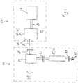
- the Figure 2 shows the drive train of the round baler 10 schematically.
- the crankshaft 80 of the internal combustion engine 74 is coupled to a transmission 82 which, on the one hand, drives a drive train to the drivable rear wheels 78 of the towing vehicle 50 (and possibly to the steerable front wheels 76), and on the other hand also drives a PTO output 84, which is driven by an articulated shaft 86 Moving elements of the round baler 10 drives.
- the propeller shaft 86 drives a transfer case 90 via a first clutch 88, which in turn drives one or more of the rollers 28, which in turn drive the conveying elements 22.
- An output of transfer case 90 is connected to roller 36 via a second clutch 92.
- the roller 36 can be coupled to the drives 54 and / or 62 via a third clutch 94.
- the clutch 88 could also be replaced or supplemented by a PTO clutch (not shown) of the towing vehicle 50, which takes over the function of the clutch 88.
- the controller 38 upon input by the operator via the input device 42, causes the first clutch 88 and the second clutch 92 to be closed.
- the third clutch 94 is opened.
- the conveying means 22, 22 'thus move and material (harvested material) entering through the inlet 26 is gradually formed into a bale 32 of continuously increasing diameter, while the towing vehicle 50 pulls the round baler 10 along a swath and the pickup 30 inwards promotes inlet 26.
- the control 38 Upon manual input by the operator into the input device 42 or when the control 38 detects that a predeterminable size of the bale 32 has been reached, the control 38 notifies the operator via the display device 40 that a wrapping process is now imminent and that he the towing vehicle 50 may stop. The stopping can also be carried out automatically by the controller 38 via the speed setting device 66.
- the controller 38 now causes the first clutch 88 to remain closed, the second clutch 92 to be opened and the third clutch 94 to be closed.
- one of the drives 54 or 62 is set in motion in order to convey the wrapping material from the supply 46 or 60 into the bale forming chamber 24, while the bale 32 continues to be driven by the conveying means 22, but no longer by the roller 36 of the conveying means 22 ' becomes.
- Mechanically actuated clutches can be selected by the operator which of the drives 54 or 62 is activated. In an advanced embodiment, this selection can be made via the input device 42 and the control 38, the corresponding couplings electromechanically or can control electrohydraulically to select the winding material.
- rollers 48 and 64 are driven via the roller 36 (which is separated from its drive train by the second clutch 92 from its drive train which drives it when the bale is formed) and which in turn is driven by friction through the bale 32, mechanically via the third clutch 94 and the drives 54 or 62.
- This ensures that the feed means is driven at exactly the circumferential speed of the bale 32 (or by a predetermined percentage slower), so that even if the bale 32 should slip relative to the conveying means 22, the wrapping material is not inserted faster than the bale 32 rotates. In this way, unwanted loop formation in the winding material is avoided and prevents the winding material from e.g. wraps around roller 36.
- the first and third couplings 88, 94 are separated and the bale 32 is ejected from the round baler 10 after opening the rear, pivotable housing half 20. A new bale 32 can then be produced.
- the round baler can also be designed as a fixed chamber press in which a number of rollers are distributed around the circumference of the bale formation chamber.
- One of these rollers then corresponds to the roller 36 of the embodiment shown here.
- the clutches 92, 94 need not be designed as disc clutches, as in the Figure 2 shown, but can be designed as belt couplings. The latter can also be mounted on the same side of the roller 36 and in particular can be actuated alternately by a single actuator.
Landscapes
- Life Sciences & Earth Sciences (AREA)
- Environmental Sciences (AREA)
- Engineering & Computer Science (AREA)
- Mechanical Engineering (AREA)
- Storage Of Harvested Produce (AREA)
Claims (4)
- Presse à balles rondes (10) comprenant :une chambre de formation de balle (24) sur la circonférence de laquelle sont répartis des éléments de transport entraînables (22, 22') qui peuvent être mis en mouvement au moyen d'une chaîne cinématique pour mettre en forme le matériau, introduit dans la chambre de pressage de balle (24), pour obtenir une balle (32), etdes moyens d'avancement qui sont conçus pour déplacer le matériau d'enveloppe d'un réservoir (46, 60) en direction de la chambre de formation de balle (24) afin d'envelopper une balle (32) produite dans la chambre de formation de balle (24),caractérisée en ce qu'une partie (22') des éléments de transport (22, 22') est reliée de manière séparable à la chaîne cinématique par le biais d'un dispositif d'accouplement (92) et peut être accouplée en entraînement aux moyens d'avancement par le biais d'un autre dispositif d'accouplement (94) et une commande (38) peut être mise en œuvre pour commander les dispositifs d'accouplement (92, 94) de telle sorte que ladite partie des éléments de transport (22') soit séparée de la chaîne cinématique pendant le processus d'enveloppe et soit accouplée aux moyens d'avancement de telle sorte que ladite partie (22') des éléments de transport (22, 22') soit entraînée par la balle (32) à envelopper pendant le processus d'enveloppe et entraîne les moyens d'avancement à une vitesse de la balle (32) qui dépend de la vitesse circonférentielle respective.
- Presse à balles rondes (10) selon la revendication 1, la partie (22') des éléments de transport (22, 22') étant un rouleau (36).
- Presse à balles rondes (10) selon la revendication 1 ou 2, le matériau d'enveloppe étant un filet, un fil ou un film.
- Procédé pour faire fonctionner une presse à balles rondes (10) qui comprend une chambre de formation de balle (24) sur la circonférence de laquelle sont répartis des éléments de transport entraînables (22, 22') qui peuvent être mis en mouvement au moyen d'une chaîne cinématique pour mettre en forme le matériau, introduit dans la chambre de pressage de balle (24), pour obtenir une balle (32), et qui comprend des moyens d'avancement qui sont conçus pour déplacer le matériau d'enveloppe d'un réservoir (46, 60) en direction de la chambre de formation de balle (24) afin d'envelopper une balle (32) produite dans la chambre de formation de balle (24), caractérisé en ce qu'une partie (22') des éléments de transport (22, 22') est séparée de la chaîne cinématique pendant le processus d'enveloppe et accouplée aux moyens d'avancement de sorte que ladite partie (22') des éléments de transport (22, 22') soit reliée de manière séparable à la chaîne cinématique par un dispositif d'accouplement (92) et puisse être accouplée en entraînement aux moyens d'avancement par un autre dispositif d'accouplement (94) et une commande (38) peut être mise en œuvre pour commander les dispositifs d'accouplement (92, 94) de telle sorte que ladite partie des éléments de transport (22') soit entraînée par la balle (32) à envelopper pendant le processus d'enveloppe et entraîne les moyens d'avancement à une vitesse qui dépend de la vitesse circonférentielle respective de la balle (32).
Applications Claiming Priority (1)
| Application Number | Priority Date | Filing Date | Title |
|---|---|---|---|
| DE102015211000.1A DE102015211000A1 (de) | 2015-06-16 | 2015-06-16 | Rundballenpresse mit Mitteln zum Umwickeln eines Ballens |
Publications (2)
| Publication Number | Publication Date |
|---|---|
| EP3106018A1 EP3106018A1 (fr) | 2016-12-21 |
| EP3106018B1 true EP3106018B1 (fr) | 2020-02-19 |
Family
ID=56087186
Family Applications (1)
| Application Number | Title | Priority Date | Filing Date |
|---|---|---|---|
| EP16171878.8A Active EP3106018B1 (fr) | 2015-06-16 | 2016-05-30 | Presse a balle avec des moyens pour emballer une balle |
Country Status (3)
| Country | Link |
|---|---|
| US (1) | US20160374271A1 (fr) |
| EP (1) | EP3106018B1 (fr) |
| DE (1) | DE102015211000A1 (fr) |
Families Citing this family (3)
| Publication number | Priority date | Publication date | Assignee | Title |
|---|---|---|---|---|
| BE1023393B1 (nl) * | 2015-07-15 | 2017-03-01 | Cnh Industrial Belgium Nv | Balenpers voor de landbouw met een achterklep in twee delen en een werkwijze voor het uitvoeren van een ontlaadsequentie |
| US11382275B2 (en) | 2016-08-31 | 2022-07-12 | Tube-Line Manufacturing Limited | Continuous round baler accumulation chamber |
| JP7157713B2 (ja) * | 2019-07-30 | 2022-10-20 | 株式会社クボタ | 走行車両および作業車両 |
Family Cites Families (17)
| Publication number | Priority date | Publication date | Assignee | Title |
|---|---|---|---|---|
| US4790125A (en) * | 1987-05-01 | 1988-12-13 | New Holland Inc. | Feed rollers for round baler net dispenser |
| US5488883A (en) * | 1992-12-18 | 1996-02-06 | Vermeer Manufacturing Company | Direct drive system for a baler |
| US5551218A (en) * | 1994-09-19 | 1996-09-03 | Gehl Company | Round baler monitoring and control system |
| US6247291B1 (en) * | 1999-07-21 | 2001-06-19 | New Holland North America, Inc. | Storage apparatus for round baler wrapping material |
| DE10153540A1 (de) | 2001-10-30 | 2003-06-26 | Deere & Co | Rundballenpresse |
| DE10309657A1 (de) * | 2003-03-06 | 2004-09-30 | Deere & Company, Moline | Vorrichtung zum Umhüllen eines Ballens mit einer Hüllbahn und Ballenpresse |
| DE102005059127A1 (de) | 2005-12-10 | 2007-06-28 | Deere & Company, Moline | Ballenpresse mit einer Feuchtemesseinrichtung |
| US7937923B2 (en) * | 2007-10-25 | 2011-05-10 | Deere & Company | Tractor and round baler combination with automatic baling and automatic rear door opening |
| EP2113165B1 (fr) * | 2008-04-30 | 2011-08-24 | Deere & Company | Dispositif d'emballage de bande |
| DE102009002439A1 (de) | 2008-11-19 | 2010-05-20 | Deere & Company, Moline | Anordnung und Verfahren zum Umwickeln eines Ballens |
| DE102009002585B4 (de) | 2009-04-23 | 2018-08-02 | Deere & Company | Rundballenpresse |
| US8581554B2 (en) * | 2009-07-10 | 2013-11-12 | Schneider Electric It Corporation | Battery charging method and apparatus |
| US8429881B2 (en) * | 2009-09-18 | 2013-04-30 | Agco Corporation | Baler starter roll |
| EP2382858B2 (fr) * | 2010-04-29 | 2020-09-02 | Deere & Company | Roto-presse avec rouleau entrainé électriquement |
| DE102011003727A1 (de) * | 2011-02-07 | 2012-08-09 | Deere & Company | Rundballenpresse mit seitlichen Führungen für den Pressriemen |
| WO2013090719A1 (fr) * | 2011-12-15 | 2013-06-20 | Agco Corporation | Cylindre en contact avec la culture entraîné par des courroies formant des balles de fourrage |
| DE102014200449A1 (de) * | 2014-01-13 | 2015-07-16 | Deere & Company | Landwirtschaftliche Rundballenpresse und Verfahren |
-
2015
- 2015-06-16 DE DE102015211000.1A patent/DE102015211000A1/de not_active Withdrawn
-
2016
- 2016-05-30 EP EP16171878.8A patent/EP3106018B1/fr active Active
- 2016-06-14 US US15/181,574 patent/US20160374271A1/en not_active Abandoned
Non-Patent Citations (1)
| Title |
|---|
| None * |
Also Published As
| Publication number | Publication date |
|---|---|
| EP3106018A1 (fr) | 2016-12-21 |
| US20160374271A1 (en) | 2016-12-29 |
| DE102015211000A1 (de) | 2016-12-22 |
Similar Documents
| Publication | Publication Date | Title |
|---|---|---|
| DE69709981T2 (de) | Rundballenpresse | |
| DE60312097T2 (de) | Rundballenpresse | |
| DE60218400T2 (de) | Rundballenpresse | |
| DE10312897B4 (de) | Vorrichtung zum Umhüllen eines Ballens mit einer Hüllbahn und Ballenpresse | |
| EP2243349B1 (fr) | Presse à ballots ronds | |
| DE102009002439A1 (de) | Anordnung und Verfahren zum Umwickeln eines Ballens | |
| DE212010000174U1 (de) | Ballenpresse zum Formen von Ballen ausFeldfrüchten | |
| EP0102530B1 (fr) | Méthode pour enlever les surcharges dûes aux amassements de récolte lors de l'enroulement de balles rondes | |
| EP3106018B1 (fr) | Presse a balle avec des moyens pour emballer une balle | |
| DE2538164C3 (de) | Rundballenpresse für Heu und anderes faseriges Erntegut mit einer Spannvorrichtung für die den Balten formenden umlaufbaren Bänder | |
| DE3301420C2 (fr) | ||
| DE60219375T2 (de) | Presse mit einer Reversiereinrichtung für den Rotor | |
| EP0535532A2 (fr) | Procédé et dispositif pour lier des balles de récolte | |
| EP1864567B1 (fr) | Ramasseur | |
| DE2530320C3 (de) | Bindevorrichtung für Wickelballenpressen | |
| DE69801615T2 (de) | Sicherheitsvorrichtung für eine Nadelauslöseeinrichtung | |
| DE2947446A1 (de) | Maschine zum formen von rundballen aus erntegut | |
| DE102007031211B4 (de) | Ballenpresse | |
| EP2042027A1 (fr) | Presse à ballots ronds | |
| EP1454521B2 (fr) | Dispositif pour envelopper des balles et presse à balles | |
| EP2556743B1 (fr) | Presse à balles rondes agricole | |
| EP2803259B1 (fr) | Combinaison d'un véhicule de traction et d'une presse à balles agricole | |
| EP3106019B1 (fr) | Presse à balle ronde et rouleau de guidage pour matériel d'enrubannage | |
| EP3300585B1 (fr) | Presse à balles rondes permettant la réception et le pressage de la récolte agricole | |
| EP4186350B1 (fr) | Procédé de fonctionnement d'une presse à balles rondes |
Legal Events
| Date | Code | Title | Description |
|---|---|---|---|
| PUAI | Public reference made under article 153(3) epc to a published international application that has entered the european phase |
Free format text: ORIGINAL CODE: 0009012 |
|
| STAA | Information on the status of an ep patent application or granted ep patent |
Free format text: STATUS: THE APPLICATION HAS BEEN PUBLISHED |
|
| AK | Designated contracting states |
Kind code of ref document: A1 Designated state(s): AL AT BE BG CH CY CZ DE DK EE ES FI FR GB GR HR HU IE IS IT LI LT LU LV MC MK MT NL NO PL PT RO RS SE SI SK SM TR |
|
| AX | Request for extension of the european patent |
Extension state: BA ME |
|
| STAA | Information on the status of an ep patent application or granted ep patent |
Free format text: STATUS: REQUEST FOR EXAMINATION WAS MADE |
|
| 17P | Request for examination filed |
Effective date: 20170621 |
|
| RBV | Designated contracting states (corrected) |
Designated state(s): AL AT BE BG CH CY CZ DE DK EE ES FI FR GB GR HR HU IE IS IT LI LT LU LV MC MK MT NL NO PL PT RO RS SE SI SK SM TR |
|
| RIC1 | Information provided on ipc code assigned before grant |
Ipc: A01F 15/07 20060101AFI20190807BHEP |
|
| GRAP | Despatch of communication of intention to grant a patent |
Free format text: ORIGINAL CODE: EPIDOSNIGR1 |
|
| STAA | Information on the status of an ep patent application or granted ep patent |
Free format text: STATUS: GRANT OF PATENT IS INTENDED |
|
| INTG | Intention to grant announced |
Effective date: 20190920 |
|
| GRAS | Grant fee paid |
Free format text: ORIGINAL CODE: EPIDOSNIGR3 |
|
| GRAA | (expected) grant |
Free format text: ORIGINAL CODE: 0009210 |
|
| STAA | Information on the status of an ep patent application or granted ep patent |
Free format text: STATUS: THE PATENT HAS BEEN GRANTED |
|
| AK | Designated contracting states |
Kind code of ref document: B1 Designated state(s): AL AT BE BG CH CY CZ DE DK EE ES FI FR GB GR HR HU IE IS IT LI LT LU LV MC MK MT NL NO PL PT RO RS SE SI SK SM TR |
|
| REG | Reference to a national code |
Ref country code: CH Ref legal event code: EP |
|
| REG | Reference to a national code |
Ref country code: DE Ref legal event code: R096 Ref document number: 502016008766 Country of ref document: DE |
|
| REG | Reference to a national code |
Ref country code: AT Ref legal event code: REF Ref document number: 1233898 Country of ref document: AT Kind code of ref document: T Effective date: 20200315 |
|
| REG | Reference to a national code |
Ref country code: IE Ref legal event code: FG4D Free format text: LANGUAGE OF EP DOCUMENT: GERMAN |
|
| REG | Reference to a national code |
Ref country code: NL Ref legal event code: MP Effective date: 20200219 |
|
| PG25 | Lapsed in a contracting state [announced via postgrant information from national office to epo] |
Ref country code: FI Free format text: LAPSE BECAUSE OF FAILURE TO SUBMIT A TRANSLATION OF THE DESCRIPTION OR TO PAY THE FEE WITHIN THE PRESCRIBED TIME-LIMIT Effective date: 20200219 Ref country code: RS Free format text: LAPSE BECAUSE OF FAILURE TO SUBMIT A TRANSLATION OF THE DESCRIPTION OR TO PAY THE FEE WITHIN THE PRESCRIBED TIME-LIMIT Effective date: 20200219 Ref country code: NO Free format text: LAPSE BECAUSE OF FAILURE TO SUBMIT A TRANSLATION OF THE DESCRIPTION OR TO PAY THE FEE WITHIN THE PRESCRIBED TIME-LIMIT Effective date: 20200519 |
|
| REG | Reference to a national code |
Ref country code: LT Ref legal event code: MG4D |
|
| PG25 | Lapsed in a contracting state [announced via postgrant information from national office to epo] |
Ref country code: IS Free format text: LAPSE BECAUSE OF FAILURE TO SUBMIT A TRANSLATION OF THE DESCRIPTION OR TO PAY THE FEE WITHIN THE PRESCRIBED TIME-LIMIT Effective date: 20200619 Ref country code: GR Free format text: LAPSE BECAUSE OF FAILURE TO SUBMIT A TRANSLATION OF THE DESCRIPTION OR TO PAY THE FEE WITHIN THE PRESCRIBED TIME-LIMIT Effective date: 20200520 Ref country code: BG Free format text: LAPSE BECAUSE OF FAILURE TO SUBMIT A TRANSLATION OF THE DESCRIPTION OR TO PAY THE FEE WITHIN THE PRESCRIBED TIME-LIMIT Effective date: 20200519 Ref country code: LV Free format text: LAPSE BECAUSE OF FAILURE TO SUBMIT A TRANSLATION OF THE DESCRIPTION OR TO PAY THE FEE WITHIN THE PRESCRIBED TIME-LIMIT Effective date: 20200219 Ref country code: SE Free format text: LAPSE BECAUSE OF FAILURE TO SUBMIT A TRANSLATION OF THE DESCRIPTION OR TO PAY THE FEE WITHIN THE PRESCRIBED TIME-LIMIT Effective date: 20200219 Ref country code: HR Free format text: LAPSE BECAUSE OF FAILURE TO SUBMIT A TRANSLATION OF THE DESCRIPTION OR TO PAY THE FEE WITHIN THE PRESCRIBED TIME-LIMIT Effective date: 20200219 |
|
| PG25 | Lapsed in a contracting state [announced via postgrant information from national office to epo] |
Ref country code: NL Free format text: LAPSE BECAUSE OF FAILURE TO SUBMIT A TRANSLATION OF THE DESCRIPTION OR TO PAY THE FEE WITHIN THE PRESCRIBED TIME-LIMIT Effective date: 20200219 |
|
| PG25 | Lapsed in a contracting state [announced via postgrant information from national office to epo] |
Ref country code: ES Free format text: LAPSE BECAUSE OF FAILURE TO SUBMIT A TRANSLATION OF THE DESCRIPTION OR TO PAY THE FEE WITHIN THE PRESCRIBED TIME-LIMIT Effective date: 20200219 Ref country code: DK Free format text: LAPSE BECAUSE OF FAILURE TO SUBMIT A TRANSLATION OF THE DESCRIPTION OR TO PAY THE FEE WITHIN THE PRESCRIBED TIME-LIMIT Effective date: 20200219 Ref country code: SK Free format text: LAPSE BECAUSE OF FAILURE TO SUBMIT A TRANSLATION OF THE DESCRIPTION OR TO PAY THE FEE WITHIN THE PRESCRIBED TIME-LIMIT Effective date: 20200219 Ref country code: PT Free format text: LAPSE BECAUSE OF FAILURE TO SUBMIT A TRANSLATION OF THE DESCRIPTION OR TO PAY THE FEE WITHIN THE PRESCRIBED TIME-LIMIT Effective date: 20200712 Ref country code: SM Free format text: LAPSE BECAUSE OF FAILURE TO SUBMIT A TRANSLATION OF THE DESCRIPTION OR TO PAY THE FEE WITHIN THE PRESCRIBED TIME-LIMIT Effective date: 20200219 Ref country code: LT Free format text: LAPSE BECAUSE OF FAILURE TO SUBMIT A TRANSLATION OF THE DESCRIPTION OR TO PAY THE FEE WITHIN THE PRESCRIBED TIME-LIMIT Effective date: 20200219 Ref country code: EE Free format text: LAPSE BECAUSE OF FAILURE TO SUBMIT A TRANSLATION OF THE DESCRIPTION OR TO PAY THE FEE WITHIN THE PRESCRIBED TIME-LIMIT Effective date: 20200219 Ref country code: RO Free format text: LAPSE BECAUSE OF FAILURE TO SUBMIT A TRANSLATION OF THE DESCRIPTION OR TO PAY THE FEE WITHIN THE PRESCRIBED TIME-LIMIT Effective date: 20200219 Ref country code: CZ Free format text: LAPSE BECAUSE OF FAILURE TO SUBMIT A TRANSLATION OF THE DESCRIPTION OR TO PAY THE FEE WITHIN THE PRESCRIBED TIME-LIMIT Effective date: 20200219 |
|
| REG | Reference to a national code |
Ref country code: DE Ref legal event code: R097 Ref document number: 502016008766 Country of ref document: DE |
|
| PLBE | No opposition filed within time limit |
Free format text: ORIGINAL CODE: 0009261 |
|
| STAA | Information on the status of an ep patent application or granted ep patent |
Free format text: STATUS: NO OPPOSITION FILED WITHIN TIME LIMIT |
|
| 26N | No opposition filed |
Effective date: 20201120 |
|
| PG25 | Lapsed in a contracting state [announced via postgrant information from national office to epo] |
Ref country code: LI Free format text: LAPSE BECAUSE OF NON-PAYMENT OF DUE FEES Effective date: 20200531 Ref country code: IT Free format text: LAPSE BECAUSE OF FAILURE TO SUBMIT A TRANSLATION OF THE DESCRIPTION OR TO PAY THE FEE WITHIN THE PRESCRIBED TIME-LIMIT Effective date: 20200219 Ref country code: CH Free format text: LAPSE BECAUSE OF NON-PAYMENT OF DUE FEES Effective date: 20200531 Ref country code: MC Free format text: LAPSE BECAUSE OF FAILURE TO SUBMIT A TRANSLATION OF THE DESCRIPTION OR TO PAY THE FEE WITHIN THE PRESCRIBED TIME-LIMIT Effective date: 20200219 |
|
| PG25 | Lapsed in a contracting state [announced via postgrant information from national office to epo] |
Ref country code: SI Free format text: LAPSE BECAUSE OF FAILURE TO SUBMIT A TRANSLATION OF THE DESCRIPTION OR TO PAY THE FEE WITHIN THE PRESCRIBED TIME-LIMIT Effective date: 20200219 Ref country code: PL Free format text: LAPSE BECAUSE OF FAILURE TO SUBMIT A TRANSLATION OF THE DESCRIPTION OR TO PAY THE FEE WITHIN THE PRESCRIBED TIME-LIMIT Effective date: 20200219 |
|
| REG | Reference to a national code |
Ref country code: BE Ref legal event code: MM Effective date: 20200531 |
|
| GBPC | Gb: european patent ceased through non-payment of renewal fee |
Effective date: 20200530 |
|
| PG25 | Lapsed in a contracting state [announced via postgrant information from national office to epo] |
Ref country code: LU Free format text: LAPSE BECAUSE OF NON-PAYMENT OF DUE FEES Effective date: 20200530 |
|
| PG25 | Lapsed in a contracting state [announced via postgrant information from national office to epo] |
Ref country code: GB Free format text: LAPSE BECAUSE OF NON-PAYMENT OF DUE FEES Effective date: 20200530 Ref country code: IE Free format text: LAPSE BECAUSE OF NON-PAYMENT OF DUE FEES Effective date: 20200530 |
|
| PG25 | Lapsed in a contracting state [announced via postgrant information from national office to epo] |
Ref country code: BE Free format text: LAPSE BECAUSE OF NON-PAYMENT OF DUE FEES Effective date: 20200531 |
|
| PG25 | Lapsed in a contracting state [announced via postgrant information from national office to epo] |
Ref country code: TR Free format text: LAPSE BECAUSE OF FAILURE TO SUBMIT A TRANSLATION OF THE DESCRIPTION OR TO PAY THE FEE WITHIN THE PRESCRIBED TIME-LIMIT Effective date: 20200219 Ref country code: MT Free format text: LAPSE BECAUSE OF FAILURE TO SUBMIT A TRANSLATION OF THE DESCRIPTION OR TO PAY THE FEE WITHIN THE PRESCRIBED TIME-LIMIT Effective date: 20200219 Ref country code: CY Free format text: LAPSE BECAUSE OF FAILURE TO SUBMIT A TRANSLATION OF THE DESCRIPTION OR TO PAY THE FEE WITHIN THE PRESCRIBED TIME-LIMIT Effective date: 20200219 |
|
| PG25 | Lapsed in a contracting state [announced via postgrant information from national office to epo] |
Ref country code: MK Free format text: LAPSE BECAUSE OF FAILURE TO SUBMIT A TRANSLATION OF THE DESCRIPTION OR TO PAY THE FEE WITHIN THE PRESCRIBED TIME-LIMIT Effective date: 20200219 Ref country code: AL Free format text: LAPSE BECAUSE OF FAILURE TO SUBMIT A TRANSLATION OF THE DESCRIPTION OR TO PAY THE FEE WITHIN THE PRESCRIBED TIME-LIMIT Effective date: 20200219 |
|
| REG | Reference to a national code |
Ref country code: AT Ref legal event code: MM01 Ref document number: 1233898 Country of ref document: AT Kind code of ref document: T Effective date: 20210530 |
|
| PG25 | Lapsed in a contracting state [announced via postgrant information from national office to epo] |
Ref country code: AT Free format text: LAPSE BECAUSE OF NON-PAYMENT OF DUE FEES Effective date: 20210530 |
|
| PGFP | Annual fee paid to national office [announced via postgrant information from national office to epo] |
Ref country code: DE Payment date: 20250423 Year of fee payment: 10 |
|
| PGFP | Annual fee paid to national office [announced via postgrant information from national office to epo] |
Ref country code: FR Payment date: 20250526 Year of fee payment: 10 |