EP3107075A1 - Dispositif d'entraînement de poignée de porte de véhicule et appareil de communication de véhicule - Google Patents
Dispositif d'entraînement de poignée de porte de véhicule et appareil de communication de véhicule Download PDFInfo
- Publication number
- EP3107075A1 EP3107075A1 EP16174084.0A EP16174084A EP3107075A1 EP 3107075 A1 EP3107075 A1 EP 3107075A1 EP 16174084 A EP16174084 A EP 16174084A EP 3107075 A1 EP3107075 A1 EP 3107075A1
- Authority
- EP
- European Patent Office
- Prior art keywords
- antenna
- voltage
- terminal
- connection wire
- detection
- Prior art date
- Legal status (The legal status is an assumption and is not a legal conclusion. Google has not performed a legal analysis and makes no representation as to the accuracy of the status listed.)
- Granted
Links
Images



Classifications
-
- G—PHYSICS
- G07—CHECKING-DEVICES
- G07C—TIME OR ATTENDANCE REGISTERS; REGISTERING OR INDICATING THE WORKING OF MACHINES; GENERATING RANDOM NUMBERS; VOTING OR LOTTERY APPARATUS; ARRANGEMENTS, SYSTEMS OR APPARATUS FOR CHECKING NOT PROVIDED FOR ELSEWHERE
- G07C9/00—Individual registration on entry or exit
- G07C9/00174—Electronically operated locks; Circuits therefor; Nonmechanical keys therefor, e.g. passive or active electrical keys or other data carriers without mechanical keys
- G07C9/00944—Details of construction or manufacture
-
- E—FIXED CONSTRUCTIONS
- E05—LOCKS; KEYS; WINDOW OR DOOR FITTINGS; SAFES
- E05B—LOCKS; ACCESSORIES THEREFOR; HANDCUFFS
- E05B81/00—Power-actuated vehicle locks
- E05B81/54—Electrical circuits
- E05B81/80—Electrical circuits characterised by the power supply; Emergency power operation
- E05B81/86—Electrical circuits characterised by the power supply; Emergency power operation using capacitors
-
- B—PERFORMING OPERATIONS; TRANSPORTING
- B60—VEHICLES IN GENERAL
- B60R—VEHICLES, VEHICLE FITTINGS, OR VEHICLE PARTS, NOT OTHERWISE PROVIDED FOR
- B60R16/00—Electric or fluid circuits specially adapted for vehicles and not otherwise provided for; Arrangement of elements of electric or fluid circuits specially adapted for vehicles and not otherwise provided for
- B60R16/02—Electric or fluid circuits specially adapted for vehicles and not otherwise provided for; Arrangement of elements of electric or fluid circuits specially adapted for vehicles and not otherwise provided for electric constitutive elements
- B60R16/023—Electric or fluid circuits specially adapted for vehicles and not otherwise provided for; Arrangement of elements of electric or fluid circuits specially adapted for vehicles and not otherwise provided for electric constitutive elements for transmission of signals between vehicle parts or subsystems
-
- E—FIXED CONSTRUCTIONS
- E05—LOCKS; KEYS; WINDOW OR DOOR FITTINGS; SAFES
- E05B—LOCKS; ACCESSORIES THEREFOR; HANDCUFFS
- E05B81/00—Power-actuated vehicle locks
- E05B81/54—Electrical circuits
- E05B81/64—Monitoring or sensing, e.g. by using switches or sensors
- E05B81/76—Detection of handle operation; Detection of a user approaching a handle; Electrical switching actions performed by door handles
- E05B81/77—Detection of handle operation; Detection of a user approaching a handle; Electrical switching actions performed by door handles comprising sensors detecting the presence of the hand of a user
-
- E—FIXED CONSTRUCTIONS
- E05—LOCKS; KEYS; WINDOW OR DOOR FITTINGS; SAFES
- E05B—LOCKS; ACCESSORIES THEREFOR; HANDCUFFS
- E05B85/00—Details of vehicle locks not provided for in groups E05B77/00 - E05B83/00
- E05B85/10—Handles
-
- H—ELECTRICITY
- H01—ELECTRIC ELEMENTS
- H01Q—ANTENNAS, i.e. RADIO AERIALS
- H01Q1/00—Details of, or arrangements associated with, antennas
- H01Q1/27—Adaptation for use in or on movable bodies
- H01Q1/32—Adaptation for use in or on road or rail vehicles
- H01Q1/3208—Adaptation for use in or on road or rail vehicles characterised by the application wherein the antenna is used
- H01Q1/3233—Adaptation for use in or on road or rail vehicles characterised by the application wherein the antenna is used particular used as part of a sensor or in a security system, e.g. for automotive radar, navigation systems
- H01Q1/3241—Adaptation for use in or on road or rail vehicles characterised by the application wherein the antenna is used particular used as part of a sensor or in a security system, e.g. for automotive radar, navigation systems particular used in keyless entry systems
-
- G—PHYSICS
- G07—CHECKING-DEVICES
- G07C—TIME OR ATTENDANCE REGISTERS; REGISTERING OR INDICATING THE WORKING OF MACHINES; GENERATING RANDOM NUMBERS; VOTING OR LOTTERY APPARATUS; ARRANGEMENTS, SYSTEMS OR APPARATUS FOR CHECKING NOT PROVIDED FOR ELSEWHERE
- G07C2209/00—Indexing scheme relating to groups G07C9/00 - G07C9/38
- G07C2209/60—Indexing scheme relating to groups G07C9/00174 - G07C9/00944
- G07C2209/63—Comprising locating means for detecting the position of the data carrier, i.e. within the vehicle or within a certain distance from the vehicle
- G07C2209/65—Comprising locating means for detecting the position of the data carrier, i.e. within the vehicle or within a certain distance from the vehicle using means for sensing the user's hand
-
- H—ELECTRICITY
- H02—GENERATION; CONVERSION OR DISTRIBUTION OF ELECTRIC POWER
- H02M—APPARATUS FOR CONVERSION BETWEEN AC AND AC, BETWEEN AC AND DC, OR BETWEEN DC AND DC, AND FOR USE WITH MAINS OR SIMILAR POWER SUPPLY SYSTEMS; CONVERSION OF DC OR AC INPUT POWER INTO SURGE OUTPUT POWER; CONTROL OR REGULATION THEREOF
- H02M7/00—Conversion of AC power input into DC power output; Conversion of DC power input into AC power output
- H02M7/42—Conversion of DC power input into AC power output without possibility of reversal
- H02M7/44—Conversion of DC power input into AC power output without possibility of reversal by static converters
- H02M7/48—Conversion of DC power input into AC power output without possibility of reversal by static converters using discharge tubes with control electrode or semiconductor devices with control electrode
- H02M7/53—Conversion of DC power input into AC power output without possibility of reversal by static converters using discharge tubes with control electrode or semiconductor devices with control electrode using devices of a triode or transistor type requiring continuous application of a control signal
- H02M7/537—Conversion of DC power input into AC power output without possibility of reversal by static converters using discharge tubes with control electrode or semiconductor devices with control electrode using devices of a triode or transistor type requiring continuous application of a control signal using semiconductor devices only, e.g. single switched pulse inverters
- H02M7/5387—Conversion of DC power input into AC power output without possibility of reversal by static converters using discharge tubes with control electrode or semiconductor devices with control electrode using devices of a triode or transistor type requiring continuous application of a control signal using semiconductor devices only, e.g. single switched pulse inverters in a bridge configuration
-
- Y—GENERAL TAGGING OF NEW TECHNOLOGICAL DEVELOPMENTS; GENERAL TAGGING OF CROSS-SECTIONAL TECHNOLOGIES SPANNING OVER SEVERAL SECTIONS OF THE IPC; TECHNICAL SUBJECTS COVERED BY FORMER USPC CROSS-REFERENCE ART COLLECTIONS [XRACs] AND DIGESTS
- Y02—TECHNOLOGIES OR APPLICATIONS FOR MITIGATION OR ADAPTATION AGAINST CLIMATE CHANGE
- Y02B—CLIMATE CHANGE MITIGATION TECHNOLOGIES RELATED TO BUILDINGS, e.g. HOUSING, HOUSE APPLIANCES OR RELATED END-USER APPLICATIONS
- Y02B70/00—Technologies for an efficient end-user side electric power management and consumption
- Y02B70/10—Technologies improving the efficiency by using switched-mode power supplies [SMPS], i.e. efficient power electronics conversion e.g. power factor correction or reduction of losses in power supplies or efficient standby modes
Definitions
- the disclosure relates to a vehicle door handle driving device and a vehicle communication apparatus.
- Japanese Patent No. 5589870 (Reference 1) and JP2014-17701A (Reference 2) disclose various vehicle door handle driving devices.
- the vehicle door handle driving device uses two electric wires (connection wires) to be connected to a door handle (vehicle-mounted device or module) including a detection member (person detection IC or sensor IC) and an antenna, and these two electric wires are used for the power supply (driving) of the antenna, for the power supply of the detection member, and for the outputting of the detection signal.
- a resonance voltage of the antenna is used.
- the resonance voltage of the antenna is used to supply the power to the detection member, and thus, it is necessary to set the resonance voltage to be equal to or less than a rated voltage of the detection member. Accordingly, it is necessary to increase the size of the antenna as the Q factor of the antenna may not be increased.
- a vehicle door handle driving device is electrically connected to an antenna and a DC driving detection member for detecting approach or touch of a person, which are mounted on a door handle and are connected in parallel, through a first connection wire and a second connection wire.
- the first connection wire is constantly connected to a first positive DC power supply, and the second connection wire is connected to a ground for a period during which the antenna is not driven.
- the vehicle door handle driving device includes: a booster capacitor whose first terminal is connected to the first DC power supply; and an inverter that is connected to the second terminal of the booster capacitor, is connected to a second positive DC power supply and the ground, is configured to generate an AC voltage having a resonance frequency of the antenna, and output the generated AC voltage to the first connection wire and the second connection wire through the booster capacitor.
- the first connection wire is constantly connected to the first DC power supply. Accordingly, for example, for a period during which the inverter is not driven (that is, for a period during which the antenna is not driven), a DC voltage of the first DC power supply is supplied to the detection member through the first and second connection wires by connecting the second connection wire to the ground. Meanwhile, for a period during which the inverter is driven (that is, for a period during which the antenna is driven), an AC voltage having a resonance frequency of the antenna is output to the first connection wire and the second connection wire through the booster capacitor.
- a voltage obtained by raising a DC component of the AC voltage having the resonance frequency of the antenna by a DC voltage of the first DC power supply is supplied to the detection member through the first and second connection wires.
- the power is supplied to the detection member irrespective of whether or not the antenna is driven.
- the power can be supplied to the detection member without using the resonance voltage especially for a period during which the antenna is driven, and thus, the resonance voltage can be set without being restricted to a rated voltage of the detection member.
- the first terminal of the booster capacitor is connected to the first DC power supply through a cathode of a diode whose anode is connected to the first DC power supply.
- the first terminal of the booster capacitor can suppress the backflow of the current toward the first DC power supply by the diode.
- a period during which the antenna is driven is divided into an oscillation period during which the AC voltage is generated and a non-oscillation period during which the AC voltage is not generated, and the second connection wire is connected to the ground during the non-oscillation period of the antenna.
- the DC voltage of the first DC power supply can be supplied to the detection member through the first and second connection wires by connecting the second connection wire to the ground.
- a vehicle communication apparatus includes: a first connection wire and a second connection wire; an antenna; a detection member that includes a power terminal and a ground terminal which are respectively connected to the first connection wire and the second connection wire, a detection output terminal which is connected to the first connection wire to output a negative detection signal indicating whether or not approach or touch of a person is detected, an antenna driving detection terminal which is connected to the first connection wire, and an antenna driving detection unit which detects a driving state of the antenna based on a voltage input to the antenna driving detection terminal; a DC cut capacitor whose both terminals are respectively connected to the detection output terminal and the antenna driving detection terminal; a passive element whose both terminals are respectively connected to the antenna driving detection terminal and the ground terminal; and the vehicle door handle driving device that further includes a lock and unlock controller which issues a lock or unlock command of a vehicle door based on the detection signal.
- the antenna driving detection terminal is connected to the first connection wire (power terminal) through the DC cut capacitor, and is connected to the second connection wire (ground terminal) through the passive element. Accordingly, for example, for a period during which the inverter is not driven (that is, for a period during which the antenna is not driven), the voltage supplied to the antenna driving detection terminal becomes zero. Therefore, if the detection signal is output in this state, the detection signal is output to the first connection wire in a state in which the detection signal is blocked from flowing to the ground by the DC cut capacitor.
- the lock and unlock controller of the vehicle door handle driving device can appropriately issue the lock or unlock command of the vehicle door based on the detection signal.
- the antenna driving detection unit can appropriately detect the driving state of the antenna.
- the driving state of the antenna can be detected without using the resonance voltage especially for a period during which the antenna is driven, and thus, the resonance voltage can be set without being restricted to the rated voltage of the antenna driving detection unit (detection member).
- the resonance voltage can be set without being restricted to the rated voltage of the antenna driving detection unit (detection member).
- an effect of further reducing the size of the antenna is exhibited.
- the present embodiment is a smart entry (registered trademark) system that locks and unlocks a vehicle door through wireless communication with a portable device carried by a user of a vehicle.
- an outside door handle 2 is provided at a door outer panel 1 constituting the vehicle door.
- the outside door handle 2 extends in forward and backward directions of the vehicle, and is attached to the door outer panel 1 at two front and rear portions thereof.
- a recess 1 a is inwardly formed in the door outer panel 1 so as to face the outside door handle 2.
- the outside door handle 2 is formed by molding, for example, a resin material into a hollow shape having an inner space. Detection areas capable of detecting approach or touch of the person are formed on an outer wall surface of the outside door handle 2. That is, a lock detection area 3 capable of detecting approach or touch of the hand of the person who intends to lock the vehicle door is formed on an outer wall surface of a front side of the outside door handle 2. An unlock detection area 4 capable of detecting approach or touch of the hand of the person who intends to unlock the vehicle door is formed on an outer wall surface of an intermediate portion as a holding portion of the outside door handle 2.
- a lock sensor electrode 5 which is made of, for example, a metal plate and has a substantially strip shape is accommodated close to a surface separated from the door outer panel 1 so as to correspond to the lock detection area 3 and an unlock sensor electrode 6 which is made of, for example, a metal plate and has a substantially strip shape is accommodated close to the door outer panel 1 so as to correspond to the unlock detection area 4.
- the unlock sensor electrode 6 is formed so as to be greater than the lock sensor electrode 5.
- a module 10 which is electrically connected to the lock sensor electrode 5 and the unlock sensor electrode 6 is accommodated.
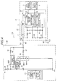
- a driving ECU 50 as the vehicle door handle driving device is connected to one end of a first electric wire W1 as a first connection wire at a first controller-side terminal T11, and the other end of the first electric wire W1 is connected to a first module-side terminal T21 of the module 10.
- the driving ECU 50 is connected to one end of a second electric wire W2 as a second connection wire at a second controller-side terminal T12, and the other end of the second electric wire W2 is connected to a second module-side terminal T22 of the module 10. That is, the driving ECU 50 and the module 10 are connected through two wires of the first and second electric wires W1 and W2.
- the driving ECU 50 and the module 10 together with the first and second electric wires W1 and W2 constitute the vehicle communication apparatus 100.
- the driving ECU 50 includes a controller 51 which includes, for example, a microcomputer as a main member.
- the controller 51 includes a lock and unlock controller 51 a, and a power supply 51 b.
- the driving ECU 50 includes a diode 52 whose anode is connected to a battery +B as a first DC power supply, and a first switch SW1 which is connected to a cathode of the diode 52.
- the driving ECU 50 includes a constant voltage circuit 53 as a second DC power supply whose one end is similarly connected to the cathode of the diode 52.
- the constant voltage circuit 53 generates an antenna driving voltage Vant ( ⁇ VB) whose voltage fluctuation is controlled based on a battery voltage VB supplied from the battery +B.
- the driving ECU 50 includes a second switch SW2 and a third switch SW3 connected to the other end of the constant voltage circuit 53 in series, and a fourth switch SW4 and a fifth switch SW5 connected to the other end of the constant voltage circuit 53 in series so as to be connected to the second and third switches in parallel.
- the third switch SW3 and the fifth switch SW5 are grounded.
- the driving ECU 50 includes a sensor detection resistor 54 whose one end is connected to the first switch SW1.
- the other end of the sensor detection resistor 54 is connected to an anode of a backflow prevention diode 55 as a diode, and a cathode of the backflow prevention diode 55 is connected to the first controller-side terminal T11 (first electric wire W1).
- the driving ECU 50 includes a booster capacitor 56 whose first terminal 56a is connected to the cathode of the backflow prevention diode 55 through a resistor 57.
- the second terminal 56b of the booster capacitor 56 is connected to a connected portion of the second switch SW2 and the third switch SW3.
- a sensor detection circuit 59 is connected between both terminals of the sensor detection resistor 54.
- the sensor detection circuit 59 obtains a voltage Vs between both the terminals of the sensor detection resistor 54.
- a connected portion of the fourth switch SW4 and the fifth switch SW5 is connected to the second controller-side terminal T12 (second electric wire W2) through a resistor 58.
- the lock and unlock controller 51 a of the controller 51 monitors the voltage Vs obtained in the sensor detection circuit 59. Meanwhile, the power supply 51 b operates to switch the first to fifth switches SW1 to SW5. Specifically, the power supply 51 b basically sets the first switch SW1 to be constantly in an ON state.
- the first controller-side terminal T11 (first electric wire W1) is constantly connected to the battery +B through the backflow prevention diode 55 and the sensor detection resistor 54.
- the power supply 51 b generates a square wave voltage VP having an amplitude double that of the antenna driving voltage Vant as an AC voltage by alternately switching between the ON and OFF states of the second and fifth switches SW2 and SW5 and the ON and OFF states of the third and fourth switches SW3 and SW4 (by allowing the polarities of the switches to be opposite to one another).
- the square wave voltage VP is output to the first controller-side terminal T11 (first electric wire W1) through the booster capacitor 56 and the resistor 57 and is output to the second controller-side terminal T12 (second electric wire W2) through the resistor 58.
- the second to fifth switches SW2 to SW5 constitute an inverter INV realized using a so-called H bridge circuit.
- the power supply 51 b sets the second to fourth switches SW2 to SW4 to be in the OFF state, and sets the fifth switch SW5 to be in the ON state.
- the second controller-side terminal T12 (second electric wire W2) is grounded.
- an antenna resonance capacitor 11 whose one end is connected to the first module-side terminal T21 is provided, and an antenna coil 12 whose one end is connected to the other end of the antenna resonance capacitor 11 is provided.
- the other end of the antenna coil 12 is connected to the second module-side terminal T22.
- the antenna resonance capacitor 11 and the antenna coil 12 constitute an LF antenna 21 as an antenna, and constitute an LC serial resonance circuit having a resonance frequency f1. Accordingly, if an AC voltage (square wave voltage) having a frequency matching the resonance frequency f1 is supplied from the driving ECU 50 through the first and second electric wires W1 and W2, the antenna coil 12 is driven, and a radio signal is output from the antenna coil 12.
- the radio signal is, for example, an inquiry signal (request signal) of the portable device carried by the user of the vehicle, and the portable device that has received the inquiry signal transmits a signal having a unique ID code.
- a sensor IC 30 as a detection member is provided in the module 10.
- the sensor IC 30 is connected to the lock sensor electrode 5 and the unlock sensor electrode 6 at a lock detection input terminal 31 and an unlock detection input terminal 32, respectively, and is connected to the first module-side terminal T21 at a detection signal output terminal 33.
- the sensor IC 30 includes a lock and unlock detection unit 30a constituting a known electrostatic sensor together with the lock sensor electrode 5 or the unlock sensor electrode 6, and supplies power to the lock sensor electrode 5 and the unlock sensor electrode 6 through the lock detection input terminal 31 and the unlock detection input terminal 32 by means of the lock and unlock detection unit 30a.
- the lock and unlock detection unit 30a detects that the hand of the person approaches or touches the lock detection area 3 or the unlock detection area 4 by respectively detecting electrostatic capacitance changes between the lock sensor electrode 5 and the door outer panel 1 and between the unlock sensor electrode 6 and the door outer panel.
- the lock and unlock detection unit 30a outputs a lock detection signal as a negative detection signal indicating whether or not the detection is performed to the first module-side terminal T21 (first electric wire W1) from the detection signal output terminal 33.
- the lock and unlock detection signal 30a includes a known switching member, and generates and outputs, for example, a lock detection signal and an unlock detection signal by causing voltage drop in the supply voltage of the driving ECU 50 with different cycles.
- the lock and unlock controller 51 a detects the lock detection signal or the unlock detection signal based on the monitored voltage Vs.
- the lock and unlock controller 51 a issues a lock command of the vehicle door through the detection of the lock detection signal and issues an unlock command of the vehicle door through the detection of the unlock detection signal.
- the sensor IC 30 is connected to one end of the resistor 41 at a power terminal 34, and the other end of the resistor 41 is connected to the first module-side terminal T21.
- the sensor IC 30 is connected to the second module-side terminal T22 at a ground terminal 35.
- a smoothing capacitor 42 is connected between the power terminal 34 and the ground terminal 35.
- the power terminal 34 is connected to the battery +B through the first electric wire W1 and the ground terminal 35 is grounded through the second electric wire W2, so that the sensor IC 30 is driven by the battery voltage VB supplied from the driving ECU 50.
- the power terminal 34 is connected to the battery +B through the first electric wire W1 and is connected to the inverter INV through the first electric wire W1 and the booster capacitor 56 and the ground terminal 35 is connected to the inverter INV through the second electric wire W2.
- the sensor IC 30 is driven by a voltage from the driving ECU 50 obtained by raising a DC component of the square wave voltage VP by the battery +B.
- the LF antenna 21 and the sensor IC 30 are electrically connected to the inverter INV (driving ECU 50) in a state in which these members are connected in parallel.
- the booster capacitor 56 serves to raise a DC component for a period during which the LF antenna 21 is driven by storing power for a period during which the sensor IC 30 is driven.
- the capacitance of the booster capacitor 56 is set to be (for example, about a hundred times or more) greater than the capacitance of the antenna resonance capacitor 11, and thus, boosting to a specified voltage is realized.
- the sensor IC 30 is connected to one end of the resistor 43 as a passive element at an antenna driving detection terminal 36, and the other end of the resistor 43 is connected to the ground terminal 35.
- a DC cut capacitor 44 is connected between the detection signal output terminal 33 and the antenna driving detection terminal 36. Accordingly, for a period during which the square wave voltage VP matching the resonance frequency f1 is supplied from the driving ECU 50 through the first and second electric wires W1 and W2 (that is, for a period during which the LF antenna 21 is driven), a DC component is removed in the DC cut capacitor 44, and a voltage divided by the DC cut capacitor 44 and the resistor 43 is supplied to the antenna driving detection terminal 36.
- the sensor IC 30 includes an antenna driving detection unit 30b, and detects the voltage divided by the DC cut capacitor 44 and the resistor 43 by means of the antenna driving detection unit 30b.
- the antenna driving detection unit 30b determines whether or not the LF antenna 21 is driving based on a level (root mean square value) of the voltage divided by the DC cut capacitor 44 and the resistor 43.
- the antenna driving detection unit 30b includes, for example, a comparator, and determines that the LF antenna 21 is driving in a case where the level of the voltage exceeds a preset threshold.
- the sensor IC 30 includes a stop controller 30c, and obtains the determination result in the antenna driving detection unit 30b by means of the stop controller 30c.
- the stop controller 30c stops the function of the sensor IC 30.
- the stop controller 30c transmits a stop command to the lock and unlock detection unit 30a, and stops outputting the detection signal from the detection signal output terminal 33.
- the stop controller 30c may stop supplying the power to the lock sensor electrode 5 and the unlock sensor electrode 6 by the lock and unlock detection unit 30a.
- the stop controller 30c may stop the entire function of the lock and unlock detection unit 30a.
- the stop controller 30c releases the function stoppage of the sensor IC 30 (resumes the function of the sensor IC 30).
- the power supply 51 b sets the first switch SW1 to be constantly in the ON state as described above. That is, the first controller-side terminal T11 (first electric wire W1) is constantly connected to the battery +B through the backflow prevention diode 55 and the sensor detection resistor 54.
- the power supply 51 b sets the second to fourth switches SW2 to SW4 to be in the OFF state, and sets the fifth switch SW5 to be in the ON state. Accordingly, the second controller-side terminal T12 (second electric wire W2) is grounded.
- the power terminal 34 is connected to the battery +B through the resistor 41 and the first module-side terminal T21 (first electric wire W1) and the ground terminal 35 is grounded through the second module-side terminal T22 (second electric wire W2), so that the battery voltage VB of the battery +B is supplied to the sensor IC 30 through the first and second electric wires W1 and W2.
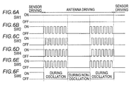
- the LF antenna 21 is switched between an oscillation period and a non-oscillation period at a frequency which is sufficiently smaller than the resonance frequency f1.
- the power supply 51 b For a period during which the LF antenna oscillates (for a period during which the square wave voltage VP is generated), the power supply 51 b generates a square wave voltage VP having a resonance frequency f1 having an amplitude double that of the antenna driving voltage Vant by alternately switching the ON and OFF states of the second and fifth switches SW2 and SW5 and the ON and OFF states of the third and fourth switches SW3 and the SW4 with the resonance frequency f1.
- the connected portion of the second and third switches SW2 and SW3 is connected to the first controller-side terminal T11 (first electric wire W1) through the booster capacitor 56, and thus, the LF antenna 21 is driven by a voltage obtained by raising a DC component of the square wave voltage VP by the battery +B.
- the sensor IC 30 is driven by a voltage obtained by raising the DC component of the square wave voltage VP by the battery +B and smoothing the voltage whose DC component is raised in the capacitor 42.
- the power supply 51 b sets the second to fourth switches SW2 to SW4 to be in the OFF state, and sets the fifth switch SW5 to be in the ON state. Accordingly, the power terminal 34 is connected to the battery +B through the resistor 41 and the first module-side terminal T21 (first electric wire W1) and the ground terminal 35 is grounded through the second module-side terminal T22 (second electric wire W2), so that the battery voltage VB of the battery +B is supplied to the sensor IC 30 through the first and second electric wires W1 and W2.
- the oscillation period and non-oscillation period of the LF antenna 21 correspond to an ON period and an OFF period of information signal (logics "1" and "0"), and the above-described inquiry signal is generated and transmitted by combinations thereof.
- the backflow prevention diode 55 is omitted, and the other end of the sensor detection resistor 54 is connected to the first controller-side terminal T11 (first electric wire W1).
- the driving ECU 60 includes a second switch SW12 and a third switch SW13 connected to the other end of the constant voltage circuit 53 in series.
- the third switch SW13 is grounded.
- the power supply 51 b generates a square wave voltage VP1 having an amplitude of the antenna driving voltage Vant by alternatively switching between the ON and OFF state of the second switch SW12 and the ON and OFF state of the third switch SW13 (by allowing the polarities of the switches to be opposite to each another) (corresponding to Figs. 3B and 3C ).
- the second and third switches SW12 and SW13 constitute an inverter INV1 realized using the so-called half bridge circuit.
- the second module-side terminal T22 of the module 10 is grounded through the electric wire W3 in place of the second electric wire W2 (for example, housing grounding through a vehicle body).
- the second connection wire that electrically connects the module 10 and the driving ECU 60 is formed by the vehicle body as the housing.
- the vehicle body (second connection wire) together with the driving ECU 60, the module 10 and the first electric wire W1 constitutes a vehicle communication apparatus 110.
- the square wave voltage VP1 generated in the inverter INV1 is output to the first controller-side terminal T11 (first electric wire W1) and the second module-side terminal T22 (electric wire W3) through the booster capacitor 56 and the resistor 57.
- a third embodiment of the vehicle door handle driving device and the vehicle communication apparatus will be described.
- a third embodiment is mainly different from the first embodiment in that a dedicated switch for grounding the ground terminal 35 of the sensor IC 30 is provided separately from the switches (SW2 to SW5) for a period during which the LF antenna 21 is driven, and thus, the detailed description of the same components will be omitted.
- the backflow prevention diode 55 is omitted, and the other end of the sensor detection resistor 54 is connected to the first controller-side terminal T11 (first electric wire W1).
- the second controller-side terminal T12 is grounded through a sixth switch SW6 interposed between the resistor 58 and the second controller-side terminal.
- the power supply 51 b sets the first switch SW1 to be constantly in the ON state.
- the power supply 51 b sets the second to fifth switches SW2 to SW5 to be in the OFF state, and sets the sixth switch SW6 to be in the ON state. Accordingly, the second controller-side terminal T12 (second electric wire W2) is grounded.
- the power terminal 34 is connected to the battery +B through the resistor 41 and the first module-side terminal T21 (first electric wire W1) and the ground terminal 35 is grounded through the second module-side terminal T22 (second electric wire W2), so that the battery voltage VB of the battery +B is supplied to the sensor IC 30 through the first and second electric wires W1 and W2.
- the power supply 51 b alternately switches the ON and OFF states of the second and fifth switches SW2 and SW5 and the ON and OFF states of the third and fourth switches SW3 and SW4 at the resonance frequency f1. Accordingly, the power supply 51 b generates the square wave voltage VP having the resonance frequency f1 having the amplitude double that of the antenna driving voltage Vant. In this case, the power supply 51 b sets the sixth switch SW6 to be in the OFF state. Accordingly, the LF antenna 21 is driven by the voltage obtained by raising the DC component of the square wave voltage VP by the battery +B.
- the sensor IC 30 is driven by the voltage obtained by raising the DC component of the square wave voltage VP by the battery +B and smoothing the voltage whose DC component is raised in the capacitor 42.
- the power supply 51 b sets the second to fifth switches SW2 to SW5 to be in the OFF state, and sets the sixth switch SW6 to be in the ON state. Accordingly, the power terminal 34 is connected to the battery +B through the resistor 41 and the first module-side terminal T21 (first electric wire W1), and the ground terminal 35 is grounded through the second module-side terminal T22 (second electric wire W2) and the sixth switch SW6. Therefore, the battery voltage VB of the battery +B is supplied to the sensor IC 30 through the first and second electric wires W1 and W2.
- the sixth switch SW6 that grounds the ground terminal 35 of the sensor IC 30 and the second to fifth switches SW2 to SW5 for a period during which the LF antenna 21 are separated, and thus, it is possible to achieve the configuration of the driving ECU 65 by combinations of cheap general-purpose ICs.
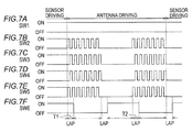
- a period during which the sensor is driven and a period during which the antenna is driven may be lapped as long as the sixth switch SW6 becomes in the OFF state. That is, the sensor driving period and the antenna driving period may not be accurately distinguished.
- a period T1 after the LF antenna 21 starts to be driven (after the LF antenna starts to oscillate) by the second to fifth switches SW2 to SW5, the sixth switch SW6 is maintained in the ON state, and the power is continuously supplied to the sensor IC 30.
- a period T2 after the LF antenna 21 is switched from the non-oscillation state to the oscillation state (after the LF antenna starts to oscillate) by the second to fifth switches SW2 to SW5, the sixth switch SW6 is maintained in the ON state, and the power is continuously supplied to the sensor IC 30.
- the LF antenna 21 can oscillate.
- the driving ECU 65 obtained by combining the general-purpose ICs may be used, and it is possible to realize the driving ECU 65 at lower cost.
Landscapes
- Engineering & Computer Science (AREA)
- Computer Security & Cryptography (AREA)
- Radar, Positioning & Navigation (AREA)
- Remote Sensing (AREA)
- Manufacturing & Machinery (AREA)
- Physics & Mathematics (AREA)
- General Physics & Mathematics (AREA)
- Mechanical Engineering (AREA)
- Power Engineering (AREA)
- Lock And Its Accessories (AREA)
Applications Claiming Priority (1)
| Application Number | Priority Date | Filing Date | Title |
|---|---|---|---|
| JP2015123575A JP6503913B2 (ja) | 2015-06-19 | 2015-06-19 | 車両用ドアハンドル駆動装置及び車両用通信装置 |
Publications (2)
| Publication Number | Publication Date |
|---|---|
| EP3107075A1 true EP3107075A1 (fr) | 2016-12-21 |
| EP3107075B1 EP3107075B1 (fr) | 2020-04-15 |
Family
ID=56131387
Family Applications (1)
| Application Number | Title | Priority Date | Filing Date |
|---|---|---|---|
| EP16174084.0A Active EP3107075B1 (fr) | 2015-06-19 | 2016-06-13 | Appareil de communication de véhicule |
Country Status (4)
| Country | Link |
|---|---|
| US (1) | US20160369534A1 (fr) |
| EP (1) | EP3107075B1 (fr) |
| JP (1) | JP6503913B2 (fr) |
| CN (1) | CN106256980B (fr) |
Cited By (1)
| Publication number | Priority date | Publication date | Assignee | Title |
|---|---|---|---|---|
| EP4209391A1 (fr) * | 2022-01-11 | 2023-07-12 | U-Shin Italia S.p.A. | Sous-ensemble de commutateur électronique à assembler sur un côté intérieur d'une portière de véhicule |
Families Citing this family (11)
| Publication number | Priority date | Publication date | Assignee | Title |
|---|---|---|---|---|
| US10132846B2 (en) * | 2016-06-14 | 2018-11-20 | Analog Devices Global | Method of and apparatus for learning the phase error or timing delays within a current transducer and power measurement apparatus including current transducer error correction |
| WO2018159463A1 (fr) * | 2017-02-28 | 2018-09-07 | 株式会社デンソー | Dispositif de commande et système de commande muni du dispositif de commande |
| JP6831291B2 (ja) * | 2017-04-28 | 2021-02-17 | 株式会社ユーシン | 車両用ドアハンドル装置 |
| FR3085984B1 (fr) * | 2018-09-18 | 2021-06-25 | Continental Automotive France | Procede de detection d'intention de verrouiller ou de deverrouiller une portiere de vehicule et dispositif de detection associe |
| US11030836B2 (en) * | 2018-11-19 | 2021-06-08 | Aisin Seiki Kabushiki Kaisha | Door lock system and handle of door for vehicle |
| JP7205183B2 (ja) * | 2018-11-19 | 2023-01-17 | 株式会社アイシン | ドア錠システムおよび車両用ドアのハンドル |
| FR3096389B1 (fr) * | 2019-05-22 | 2021-08-13 | Continental Automotive Gmbh | Capteur et dispositif de détection de présence |
| DE102019121920A1 (de) * | 2019-08-14 | 2021-02-18 | Huf Hülsbeck & Fürst Gmbh & Co. Kg | Anordnung zur Informationsübertragung bei einer Komponente eines Fahrzeuges |
| DE102020102775A1 (de) * | 2020-02-04 | 2021-08-05 | Brose Fahrzeugteile Se & Co. Kommanditgesellschaft, Bamberg | Steueranordnung für den Betrieb eines Kraftfahrzeugschließsystems |
| CN113511154B (zh) * | 2020-04-10 | 2023-10-03 | 广州汽车集团股份有限公司 | 一种车辆强制休眠控制方法、装置及车辆 |
| WO2021235052A1 (fr) * | 2020-05-19 | 2021-11-25 | アルプスアルパイン株式会社 | Dispositif d'entrée électrostatique |
Citations (3)
| Publication number | Priority date | Publication date | Assignee | Title |
|---|---|---|---|---|
| JP2009084829A (ja) * | 2007-09-28 | 2009-04-23 | Denso Corp | スマートキーシステム |
| EP2685435A2 (fr) * | 2012-07-10 | 2014-01-15 | Aisin Seiki Kabushiki Kaisha | Appareil de commande d'antenne |
| JP5589870B2 (ja) | 2011-01-27 | 2014-09-17 | アイシン精機株式会社 | 車両用ドアハンドル装置 |
Family Cites Families (4)
| Publication number | Priority date | Publication date | Assignee | Title |
|---|---|---|---|---|
| JP4925181B2 (ja) * | 2006-03-09 | 2012-04-25 | 国立大学法人長岡技術科学大学 | 電力システム |
| US7646182B2 (en) * | 2006-03-29 | 2010-01-12 | Mitsubishi Electric Corporation | Power supply apparatus |
| DE102009057005A1 (de) * | 2009-12-04 | 2011-06-09 | Audi Ag | Türgriff für eine Fahrzeugtür |
| DE102012101882A1 (de) * | 2012-03-06 | 2013-09-12 | Huf Hülsbeck & Fürst Gmbh & Co. Kg | Fahrzeugtürgriff mit kapazitivem Annäherungssensor |
-
2015
- 2015-06-19 JP JP2015123575A patent/JP6503913B2/ja active Active
-
2016
- 2016-04-18 US US15/131,055 patent/US20160369534A1/en not_active Abandoned
- 2016-06-12 CN CN201610408049.XA patent/CN106256980B/zh active Active
- 2016-06-13 EP EP16174084.0A patent/EP3107075B1/fr active Active
Patent Citations (4)
| Publication number | Priority date | Publication date | Assignee | Title |
|---|---|---|---|---|
| JP2009084829A (ja) * | 2007-09-28 | 2009-04-23 | Denso Corp | スマートキーシステム |
| JP5589870B2 (ja) | 2011-01-27 | 2014-09-17 | アイシン精機株式会社 | 車両用ドアハンドル装置 |
| EP2685435A2 (fr) * | 2012-07-10 | 2014-01-15 | Aisin Seiki Kabushiki Kaisha | Appareil de commande d'antenne |
| JP2014017701A (ja) | 2012-07-10 | 2014-01-30 | Aisin Seiki Co Ltd | アンテナ駆動装置 |
Cited By (2)
| Publication number | Priority date | Publication date | Assignee | Title |
|---|---|---|---|---|
| EP4209391A1 (fr) * | 2022-01-11 | 2023-07-12 | U-Shin Italia S.p.A. | Sous-ensemble de commutateur électronique à assembler sur un côté intérieur d'une portière de véhicule |
| WO2023135146A1 (fr) * | 2022-01-11 | 2023-07-20 | Minebea Accesssolutions Italia S.P.A. | Sous-ensemble de commutateur électronique destiné à être assemblé au niveau d'un côté interne d'une porte de véhicule |
Also Published As
| Publication number | Publication date |
|---|---|
| JP6503913B2 (ja) | 2019-04-24 |
| EP3107075B1 (fr) | 2020-04-15 |
| US20160369534A1 (en) | 2016-12-22 |
| CN106256980A (zh) | 2016-12-28 |
| CN106256980B (zh) | 2019-03-12 |
| JP2017008538A (ja) | 2017-01-12 |
Similar Documents
| Publication | Publication Date | Title |
|---|---|---|
| EP3107075B1 (fr) | Appareil de communication de véhicule | |
| EP3107074B1 (fr) | Dispositif de poignée de porte de véhicule | |
| US8854114B2 (en) | Antenna drive apparatus | |
| EP3124333B1 (fr) | Appareil de commande d'antenne | |
| US8330594B2 (en) | Tire pressure measuring system and tire pressure measuring device | |
| JP5589870B2 (ja) | 車両用ドアハンドル装置 | |
| JP5589869B2 (ja) | 車両用ドアハンドル装置 | |
| US9892575B2 (en) | Vehicle opening-and-closing member locking-and-unlocking apparatus | |
| CN110260892B (zh) | 电感式传感器和用于运行电感式传感器的方法 | |
| JP2019035202A (ja) | 車両用ドアハンドル装置 | |
| US10227797B2 (en) | Door handle device for vehicle | |
| JP2001055852A (ja) | 静電容量形近接センサ及び該センサを用いた錠制御装置 | |
| US7469580B2 (en) | Tire inflation pressure determining system and tire inflation pressure determining apparatus | |
| CN221457765U (zh) | 方向盘总成及汽车 | |
| US10767398B2 (en) | Vehicle door handle having a control circuit |
Legal Events
| Date | Code | Title | Description |
|---|---|---|---|
| PUAI | Public reference made under article 153(3) epc to a published international application that has entered the european phase |
Free format text: ORIGINAL CODE: 0009012 |
|
| STAA | Information on the status of an ep patent application or granted ep patent |
Free format text: STATUS: THE APPLICATION HAS BEEN PUBLISHED |
|
| AK | Designated contracting states |
Kind code of ref document: A1 Designated state(s): AL AT BE BG CH CY CZ DE DK EE ES FI FR GB GR HR HU IE IS IT LI LT LU LV MC MK MT NL NO PL PT RO RS SE SI SK SM TR |
|
| AX | Request for extension of the european patent |
Extension state: BA ME |
|
| STAA | Information on the status of an ep patent application or granted ep patent |
Free format text: STATUS: REQUEST FOR EXAMINATION WAS MADE |
|
| 17P | Request for examination filed |
Effective date: 20170616 |
|
| RBV | Designated contracting states (corrected) |
Designated state(s): AL AT BE BG CH CY CZ DE DK EE ES FI FR GB GR HR HU IE IS IT LI LT LU LV MC MK MT NL NO PL PT RO RS SE SI SK SM TR |
|
| STAA | Information on the status of an ep patent application or granted ep patent |
Free format text: STATUS: EXAMINATION IS IN PROGRESS |
|
| 17Q | First examination report despatched |
Effective date: 20190607 |
|
| GRAP | Despatch of communication of intention to grant a patent |
Free format text: ORIGINAL CODE: EPIDOSNIGR1 |
|
| STAA | Information on the status of an ep patent application or granted ep patent |
Free format text: STATUS: GRANT OF PATENT IS INTENDED |
|
| INTG | Intention to grant announced |
Effective date: 20191107 |
|
| GRAS | Grant fee paid |
Free format text: ORIGINAL CODE: EPIDOSNIGR3 |
|
| GRAA | (expected) grant |
Free format text: ORIGINAL CODE: 0009210 |
|
| STAA | Information on the status of an ep patent application or granted ep patent |
Free format text: STATUS: THE PATENT HAS BEEN GRANTED |
|
| AK | Designated contracting states |
Kind code of ref document: B1 Designated state(s): AL AT BE BG CH CY CZ DE DK EE ES FI FR GB GR HR HU IE IS IT LI LT LU LV MC MK MT NL NO PL PT RO RS SE SI SK SM TR |
|
| REG | Reference to a national code |
Ref country code: CH Ref legal event code: EP |
|
| REG | Reference to a national code |
Ref country code: DE Ref legal event code: R096 Ref document number: 602016033919 Country of ref document: DE |
|
| REG | Reference to a national code |
Ref country code: IE Ref legal event code: FG4D |
|
| REG | Reference to a national code |
Ref country code: AT Ref legal event code: REF Ref document number: 1258187 Country of ref document: AT Kind code of ref document: T Effective date: 20200515 |
|
| REG | Reference to a national code |
Ref country code: NL Ref legal event code: MP Effective date: 20200415 |
|
| REG | Reference to a national code |
Ref country code: LT Ref legal event code: MG4D |
|
| PG25 | Lapsed in a contracting state [announced via postgrant information from national office to epo] |
Ref country code: NL Free format text: LAPSE BECAUSE OF FAILURE TO SUBMIT A TRANSLATION OF THE DESCRIPTION OR TO PAY THE FEE WITHIN THE PRESCRIBED TIME-LIMIT Effective date: 20200415 Ref country code: LT Free format text: LAPSE BECAUSE OF FAILURE TO SUBMIT A TRANSLATION OF THE DESCRIPTION OR TO PAY THE FEE WITHIN THE PRESCRIBED TIME-LIMIT Effective date: 20200415 Ref country code: NO Free format text: LAPSE BECAUSE OF FAILURE TO SUBMIT A TRANSLATION OF THE DESCRIPTION OR TO PAY THE FEE WITHIN THE PRESCRIBED TIME-LIMIT Effective date: 20200715 Ref country code: GR Free format text: LAPSE BECAUSE OF FAILURE TO SUBMIT A TRANSLATION OF THE DESCRIPTION OR TO PAY THE FEE WITHIN THE PRESCRIBED TIME-LIMIT Effective date: 20200716 Ref country code: FI Free format text: LAPSE BECAUSE OF FAILURE TO SUBMIT A TRANSLATION OF THE DESCRIPTION OR TO PAY THE FEE WITHIN THE PRESCRIBED TIME-LIMIT Effective date: 20200415 Ref country code: SE Free format text: LAPSE BECAUSE OF FAILURE TO SUBMIT A TRANSLATION OF THE DESCRIPTION OR TO PAY THE FEE WITHIN THE PRESCRIBED TIME-LIMIT Effective date: 20200415 Ref country code: IS Free format text: LAPSE BECAUSE OF FAILURE TO SUBMIT A TRANSLATION OF THE DESCRIPTION OR TO PAY THE FEE WITHIN THE PRESCRIBED TIME-LIMIT Effective date: 20200815 Ref country code: PT Free format text: LAPSE BECAUSE OF FAILURE TO SUBMIT A TRANSLATION OF THE DESCRIPTION OR TO PAY THE FEE WITHIN THE PRESCRIBED TIME-LIMIT Effective date: 20200817 |
|
| REG | Reference to a national code |
Ref country code: AT Ref legal event code: MK05 Ref document number: 1258187 Country of ref document: AT Kind code of ref document: T Effective date: 20200415 |
|
| PG25 | Lapsed in a contracting state [announced via postgrant information from national office to epo] |
Ref country code: LV Free format text: LAPSE BECAUSE OF FAILURE TO SUBMIT A TRANSLATION OF THE DESCRIPTION OR TO PAY THE FEE WITHIN THE PRESCRIBED TIME-LIMIT Effective date: 20200415 Ref country code: HR Free format text: LAPSE BECAUSE OF FAILURE TO SUBMIT A TRANSLATION OF THE DESCRIPTION OR TO PAY THE FEE WITHIN THE PRESCRIBED TIME-LIMIT Effective date: 20200415 Ref country code: RS Free format text: LAPSE BECAUSE OF FAILURE TO SUBMIT A TRANSLATION OF THE DESCRIPTION OR TO PAY THE FEE WITHIN THE PRESCRIBED TIME-LIMIT Effective date: 20200415 Ref country code: BG Free format text: LAPSE BECAUSE OF FAILURE TO SUBMIT A TRANSLATION OF THE DESCRIPTION OR TO PAY THE FEE WITHIN THE PRESCRIBED TIME-LIMIT Effective date: 20200715 |
|
| PG25 | Lapsed in a contracting state [announced via postgrant information from national office to epo] |
Ref country code: AL Free format text: LAPSE BECAUSE OF FAILURE TO SUBMIT A TRANSLATION OF THE DESCRIPTION OR TO PAY THE FEE WITHIN THE PRESCRIBED TIME-LIMIT Effective date: 20200415 |
|
| REG | Reference to a national code |
Ref country code: DE Ref legal event code: R097 Ref document number: 602016033919 Country of ref document: DE |
|
| PG25 | Lapsed in a contracting state [announced via postgrant information from national office to epo] |
Ref country code: IT Free format text: LAPSE BECAUSE OF FAILURE TO SUBMIT A TRANSLATION OF THE DESCRIPTION OR TO PAY THE FEE WITHIN THE PRESCRIBED TIME-LIMIT Effective date: 20200415 Ref country code: MC Free format text: LAPSE BECAUSE OF FAILURE TO SUBMIT A TRANSLATION OF THE DESCRIPTION OR TO PAY THE FEE WITHIN THE PRESCRIBED TIME-LIMIT Effective date: 20200415 Ref country code: DK Free format text: LAPSE BECAUSE OF FAILURE TO SUBMIT A TRANSLATION OF THE DESCRIPTION OR TO PAY THE FEE WITHIN THE PRESCRIBED TIME-LIMIT Effective date: 20200415 Ref country code: AT Free format text: LAPSE BECAUSE OF FAILURE TO SUBMIT A TRANSLATION OF THE DESCRIPTION OR TO PAY THE FEE WITHIN THE PRESCRIBED TIME-LIMIT Effective date: 20200415 Ref country code: EE Free format text: LAPSE BECAUSE OF FAILURE TO SUBMIT A TRANSLATION OF THE DESCRIPTION OR TO PAY THE FEE WITHIN THE PRESCRIBED TIME-LIMIT Effective date: 20200415 Ref country code: SM Free format text: LAPSE BECAUSE OF FAILURE TO SUBMIT A TRANSLATION OF THE DESCRIPTION OR TO PAY THE FEE WITHIN THE PRESCRIBED TIME-LIMIT Effective date: 20200415 Ref country code: ES Free format text: LAPSE BECAUSE OF FAILURE TO SUBMIT A TRANSLATION OF THE DESCRIPTION OR TO PAY THE FEE WITHIN THE PRESCRIBED TIME-LIMIT Effective date: 20200415 Ref country code: RO Free format text: LAPSE BECAUSE OF FAILURE TO SUBMIT A TRANSLATION OF THE DESCRIPTION OR TO PAY THE FEE WITHIN THE PRESCRIBED TIME-LIMIT Effective date: 20200415 Ref country code: CZ Free format text: LAPSE BECAUSE OF FAILURE TO SUBMIT A TRANSLATION OF THE DESCRIPTION OR TO PAY THE FEE WITHIN THE PRESCRIBED TIME-LIMIT Effective date: 20200415 |
|
| REG | Reference to a national code |
Ref country code: CH Ref legal event code: PL |
|
| PLBE | No opposition filed within time limit |
Free format text: ORIGINAL CODE: 0009261 |
|
| STAA | Information on the status of an ep patent application or granted ep patent |
Free format text: STATUS: NO OPPOSITION FILED WITHIN TIME LIMIT |
|
| PG25 | Lapsed in a contracting state [announced via postgrant information from national office to epo] |
Ref country code: SK Free format text: LAPSE BECAUSE OF FAILURE TO SUBMIT A TRANSLATION OF THE DESCRIPTION OR TO PAY THE FEE WITHIN THE PRESCRIBED TIME-LIMIT Effective date: 20200415 Ref country code: PL Free format text: LAPSE BECAUSE OF FAILURE TO SUBMIT A TRANSLATION OF THE DESCRIPTION OR TO PAY THE FEE WITHIN THE PRESCRIBED TIME-LIMIT Effective date: 20200415 |
|
| 26N | No opposition filed |
Effective date: 20210118 |
|
| GBPC | Gb: european patent ceased through non-payment of renewal fee |
Effective date: 20200715 |
|
| PG25 | Lapsed in a contracting state [announced via postgrant information from national office to epo] |
Ref country code: LU Free format text: LAPSE BECAUSE OF NON-PAYMENT OF DUE FEES Effective date: 20200613 |
|
| REG | Reference to a national code |
Ref country code: BE Ref legal event code: MM Effective date: 20200630 |
|
| PG25 | Lapsed in a contracting state [announced via postgrant information from national office to epo] |
Ref country code: IE Free format text: LAPSE BECAUSE OF NON-PAYMENT OF DUE FEES Effective date: 20200613 Ref country code: GB Free format text: LAPSE BECAUSE OF NON-PAYMENT OF DUE FEES Effective date: 20200715 Ref country code: FR Free format text: LAPSE BECAUSE OF NON-PAYMENT OF DUE FEES Effective date: 20200615 Ref country code: LI Free format text: LAPSE BECAUSE OF NON-PAYMENT OF DUE FEES Effective date: 20200630 Ref country code: CH Free format text: LAPSE BECAUSE OF NON-PAYMENT OF DUE FEES Effective date: 20200630 |
|
| PG25 | Lapsed in a contracting state [announced via postgrant information from national office to epo] |
Ref country code: BE Free format text: LAPSE BECAUSE OF NON-PAYMENT OF DUE FEES Effective date: 20200630 Ref country code: SI Free format text: LAPSE BECAUSE OF FAILURE TO SUBMIT A TRANSLATION OF THE DESCRIPTION OR TO PAY THE FEE WITHIN THE PRESCRIBED TIME-LIMIT Effective date: 20200415 |
|
| PG25 | Lapsed in a contracting state [announced via postgrant information from national office to epo] |
Ref country code: TR Free format text: LAPSE BECAUSE OF FAILURE TO SUBMIT A TRANSLATION OF THE DESCRIPTION OR TO PAY THE FEE WITHIN THE PRESCRIBED TIME-LIMIT Effective date: 20200415 Ref country code: MT Free format text: LAPSE BECAUSE OF FAILURE TO SUBMIT A TRANSLATION OF THE DESCRIPTION OR TO PAY THE FEE WITHIN THE PRESCRIBED TIME-LIMIT Effective date: 20200415 Ref country code: CY Free format text: LAPSE BECAUSE OF FAILURE TO SUBMIT A TRANSLATION OF THE DESCRIPTION OR TO PAY THE FEE WITHIN THE PRESCRIBED TIME-LIMIT Effective date: 20200415 |
|
| PG25 | Lapsed in a contracting state [announced via postgrant information from national office to epo] |
Ref country code: MK Free format text: LAPSE BECAUSE OF FAILURE TO SUBMIT A TRANSLATION OF THE DESCRIPTION OR TO PAY THE FEE WITHIN THE PRESCRIBED TIME-LIMIT Effective date: 20200415 |
|
| PGFP | Annual fee paid to national office [announced via postgrant information from national office to epo] |
Ref country code: DE Payment date: 20250429 Year of fee payment: 10 |