EP3107441B1 - Appareil capable d'avancer le long d'une trajectoire incurvée prédéterminée, et son procédé de fonctionnement - Google Patents
Appareil capable d'avancer le long d'une trajectoire incurvée prédéterminée, et son procédé de fonctionnement Download PDFInfo
- Publication number
- EP3107441B1 EP3107441B1 EP15752740.9A EP15752740A EP3107441B1 EP 3107441 B1 EP3107441 B1 EP 3107441B1 EP 15752740 A EP15752740 A EP 15752740A EP 3107441 B1 EP3107441 B1 EP 3107441B1
- Authority
- EP
- European Patent Office
- Prior art keywords
- additional
- segmented assembly
- segment
- state
- segments
- Prior art date
- Legal status (The legal status is an assumption and is not a legal conclusion. Google has not performed a legal analysis and makes no representation as to the accuracy of the status listed.)
- Not-in-force
Links
Images





Classifications
-
- F—MECHANICAL ENGINEERING; LIGHTING; HEATING; WEAPONS; BLASTING
- F16—ENGINEERING ELEMENTS AND UNITS; GENERAL MEASURES FOR PRODUCING AND MAINTAINING EFFECTIVE FUNCTIONING OF MACHINES OR INSTALLATIONS; THERMAL INSULATION IN GENERAL
- F16H—GEARING
- F16H19/00—Gearings comprising essentially only toothed gears or friction members and not capable of conveying indefinitely-continuing rotary motion
- F16H19/02—Gearings comprising essentially only toothed gears or friction members and not capable of conveying indefinitely-continuing rotary motion for interconverting rotary or oscillating motion and reciprocating motion
- F16H19/06—Gearings comprising essentially only toothed gears or friction members and not capable of conveying indefinitely-continuing rotary motion for interconverting rotary or oscillating motion and reciprocating motion comprising flexible members, e.g. an endless flexible member
- F16H19/0636—Gearings comprising essentially only toothed gears or friction members and not capable of conveying indefinitely-continuing rotary motion for interconverting rotary or oscillating motion and reciprocating motion comprising flexible members, e.g. an endless flexible member the flexible member being a non-buckling chain
-
- A—HUMAN NECESSITIES
- A61—MEDICAL OR VETERINARY SCIENCE; HYGIENE
- A61B—DIAGNOSIS; SURGERY; IDENTIFICATION
- A61B1/00—Instruments for performing medical examinations of the interior of cavities or tubes of the body by visual or photographical inspection, e.g. endoscopes; Illuminating arrangements therefor
- A61B1/005—Flexible endoscopes
- A61B1/008—Articulations
-
- A—HUMAN NECESSITIES
- A61—MEDICAL OR VETERINARY SCIENCE; HYGIENE
- A61B—DIAGNOSIS; SURGERY; IDENTIFICATION
- A61B17/00—Surgical instruments, devices or methods
- A61B17/00234—Surgical instruments, devices or methods for minimally invasive surgery
-
- F—MECHANICAL ENGINEERING; LIGHTING; HEATING; WEAPONS; BLASTING
- F16—ENGINEERING ELEMENTS AND UNITS; GENERAL MEASURES FOR PRODUCING AND MAINTAINING EFFECTIVE FUNCTIONING OF MACHINES OR INSTALLATIONS; THERMAL INSULATION IN GENERAL
- F16C—SHAFTS; FLEXIBLE SHAFTS; ELEMENTS OR CRANKSHAFT MECHANISMS; ROTARY BODIES OTHER THAN GEARING ELEMENTS; BEARINGS
- F16C1/00—Flexible shafts; Mechanical means for transmitting movement in a flexible sheathing
- F16C1/02—Flexible shafts; Mechanical means for transmitting movement in a flexible sheathing for conveying rotary movements
-
- F—MECHANICAL ENGINEERING; LIGHTING; HEATING; WEAPONS; BLASTING
- F16—ENGINEERING ELEMENTS AND UNITS; GENERAL MEASURES FOR PRODUCING AND MAINTAINING EFFECTIVE FUNCTIONING OF MACHINES OR INSTALLATIONS; THERMAL INSULATION IN GENERAL
- F16G—BELTS, CABLES, OR ROPES, PREDOMINANTLY USED FOR DRIVING PURPOSES; CHAINS; FITTINGS PREDOMINANTLY USED THEREFOR
- F16G13/00—Chains
- F16G13/18—Chains having special overall characteristics
- F16G13/20—Chains having special overall characteristics stiff; Push-pull chains
-
- F—MECHANICAL ENGINEERING; LIGHTING; HEATING; WEAPONS; BLASTING
- F16—ENGINEERING ELEMENTS AND UNITS; GENERAL MEASURES FOR PRODUCING AND MAINTAINING EFFECTIVE FUNCTIONING OF MACHINES OR INSTALLATIONS; THERMAL INSULATION IN GENERAL
- F16H—GEARING
- F16H19/00—Gearings comprising essentially only toothed gears or friction members and not capable of conveying indefinitely-continuing rotary motion
- F16H19/02—Gearings comprising essentially only toothed gears or friction members and not capable of conveying indefinitely-continuing rotary motion for interconverting rotary or oscillating motion and reciprocating motion
- F16H19/04—Gearings comprising essentially only toothed gears or friction members and not capable of conveying indefinitely-continuing rotary motion for interconverting rotary or oscillating motion and reciprocating motion comprising a rack
-
- A—HUMAN NECESSITIES
- A61—MEDICAL OR VETERINARY SCIENCE; HYGIENE
- A61B—DIAGNOSIS; SURGERY; IDENTIFICATION
- A61B17/00—Surgical instruments, devices or methods
- A61B17/00234—Surgical instruments, devices or methods for minimally invasive surgery
- A61B2017/00292—Surgical instruments, devices or methods for minimally invasive surgery mounted on or guided by flexible, e.g. catheter-like, means
- A61B2017/003—Steerable
- A61B2017/00305—Constructional details of the flexible means
- A61B2017/00314—Separate linked members
-
- A—HUMAN NECESSITIES
- A61—MEDICAL OR VETERINARY SCIENCE; HYGIENE
- A61B—DIAGNOSIS; SURGERY; IDENTIFICATION
- A61B17/00—Surgical instruments, devices or methods
- A61B17/00234—Surgical instruments, devices or methods for minimally invasive surgery
- A61B2017/00292—Surgical instruments, devices or methods for minimally invasive surgery mounted on or guided by flexible, e.g. catheter-like, means
- A61B2017/003—Steerable
- A61B2017/00318—Steering mechanisms
- A61B2017/00331—Steering mechanisms with preformed bends
-
- A—HUMAN NECESSITIES
- A61—MEDICAL OR VETERINARY SCIENCE; HYGIENE
- A61B—DIAGNOSIS; SURGERY; IDENTIFICATION
- A61B17/00—Surgical instruments, devices or methods
- A61B17/00234—Surgical instruments, devices or methods for minimally invasive surgery
- A61B2017/00292—Surgical instruments, devices or methods for minimally invasive surgery mounted on or guided by flexible, e.g. catheter-like, means
- A61B2017/00336—Surgical instruments, devices or methods for minimally invasive surgery mounted on or guided by flexible, e.g. catheter-like, means with a protective sleeve, e.g. retractable or slidable
-
- F—MECHANICAL ENGINEERING; LIGHTING; HEATING; WEAPONS; BLASTING
- F16—ENGINEERING ELEMENTS AND UNITS; GENERAL MEASURES FOR PRODUCING AND MAINTAINING EFFECTIVE FUNCTIONING OF MACHINES OR INSTALLATIONS; THERMAL INSULATION IN GENERAL
- F16H—GEARING
- F16H19/00—Gearings comprising essentially only toothed gears or friction members and not capable of conveying indefinitely-continuing rotary motion
- F16H19/02—Gearings comprising essentially only toothed gears or friction members and not capable of conveying indefinitely-continuing rotary motion for interconverting rotary or oscillating motion and reciprocating motion
- F16H19/06—Gearings comprising essentially only toothed gears or friction members and not capable of conveying indefinitely-continuing rotary motion for interconverting rotary or oscillating motion and reciprocating motion comprising flexible members, e.g. an endless flexible member
- F16H2019/069—Gearings comprising essentially only toothed gears or friction members and not capable of conveying indefinitely-continuing rotary motion for interconverting rotary or oscillating motion and reciprocating motion comprising flexible members, e.g. an endless flexible member with means for generating two superposed movements, e.g. for driving a X-Y table
Definitions
- the presently disclosed subject matter is related to the field of apparatuses used for introduction into a structure, in particular, apparatuses made for advancement along a predetermined curved trajectory.
- Apparatuses for introduction into a structure via an opening have been known for many years, and are used for different applications.
- these apparatuses are known as: drills which are used in mechanical engineering, catheters which are used in medical endoscopy, monitoring devices which are used for various monitoring purposes, etc.
- drills which are used in mechanical engineering
- catheters which are used in medical endoscopy
- monitoring devices which are used for various monitoring purposes, etc.
- the presently disclosed subject matter is related to an apparatus and a method for introduction into an object along a straight path and advancement therein along a predetermined curved trajectory.
- the apparatus and the method can be used for a wide variety of applications, for example: constituting a carrier for introducing an least one object into a structure; monitoring a particular location within a structure; forming a curved channel within or though a structure; clearing a path within a structure, e.g., by drilling; providing a curved anchoring member within a structure; forming a reinforcing member within a structure; cutting-out a sample of material from a structure; filling a region within a structure; and expanding a spacing between parts of a structure.
- the term 'structure' refers hereinafter in the specification and the claims to any part or element known in the fields of medicine, mechanics, physics, engineering, etc.
- the structure can be for example, a human body; an animal body; and an inanimate object.
- the structure can be made, for example, of the following materials or combination thereof: concrete, wood, metal, plastics and soil, etc.
- an apparatus for advancement along a predetermined curved trajectory comprising:
- the segmented assembly when in its curved configuration can have a concave side and a convex side. At least in a majority of the segments, each pair of adjacent segments can have stabilizing portions which are closer to the convex side than the concave side and that are other than the hinged connection therebetween.
- the stabilizing portions can be configured to engage each other in both the straight and the curved configurations of the segmented assembly so as to resist torsion of the adjacent segments with respect to each other.
- the hinges can be disposed closer to the concave side than the deflecting member.
- any one or more of the following features, designs and configurations can be incorporated in the apparatus according to the presently disclosed subject matter, independently or in combination thereof:
- the segments associated with the part of the assembly can be restricted by an internal wall of the conduit to assume their parallel orientation with respect to each other.
- both the deflecting member and the moving mechanism to apply pushing forces at the same direction allows effectively advancing the segment assembly into the structure.
- the fact that the direction of movement of the deflecting member is similar to that of the elongated member allows the deflecting member to assist in the advancement of the elongated member into the structure and to improve this advancement.
- the number of the additional segments can be identical to the number of the segments of the segmented assembly.
- the curved shape can be similar or identical to the additional curved shape.
- the actuator can be constituted by the segmented assembly and by the additional segmented assembly so that: operation of the moving mechanism to move the elongated member along the conduit to cause said segmented assembly to extend from the conduit distal end, entails the part of the additional segmented assembly to change its configuration from the additional curved configuration to the additional straight configuration, which entails the most proximal segment of the additional segmented assembly to exert a pushing force of the proximal end on the deflecting member, causing it to move in the same direction and to change its state from the first to the second state, thereby changing the configuration of the segmented assembly from the straight to the curved configuration; and operation of the moving mechanism to move the elongated member along the conduit to cause said segmented assembly to be introduced into the conduit via the conduit distal end, entails the segmented assembly to change its configuration from the curved configuration to the straight configuration, which entails the most distal segment to exert a pushing force on the distal end of the deflecting member,
- the apparatus comprises a housing having a curved channel.
- the curved channel can have a straight portion extending along the conduit for housing the additional segmented assembly in its additional straight configuration and a curved portion for housing the part of the additional segmented assembly therein in the additional curved configuration of the additional segmented assembly.
- the additional segmented assembly can be movable within the curved channel between its additional straight configuration and additional curved configuration.
- the moving mechanism can comprise a rack and pinion gear in which the pinion is a circular gear and the rack is a linear gear formed along the elongated member.
- the stabilizing portions can be constituted by a projecting portion of one segment and a recessed portion of its adjacent segment, configured to receive the projecting portion.
- the hinges can be disposed in proximity to the concave side and the deflecting member can be disposed in proximity to the convex side.
- the curved shape can be an arc characterized by a center of curvature O facing the concave side and a radius R defined between the main axis and the center of curvature O.
- the hinges of the part of the segmented assembly can be equally spaced from the center of curvature O to a first distance D1 and the deflecting member extending along a first channel formed in the elongated member.
- the first channel can be spaced from the center of curvature O to a second distance D2 and the following condition is fulfilled: D1 ⁇ R ⁇ D2.
- Each segment of at least a majority of said segments can comprise: an inner segment face constituting a part of the concave side; an outer segment face opposite thereto, constituting a part of the convex side; first and second opposite outer wings, constituting at least a part of the recessed portion, respectively extending between the inner segment face and the outer segment face therebetween; and first and second opposite inner wings, constituting at least a part of the projecting portion, respectively extending between the inner segment face and the outer segment face.
- the first and second inner wings of one segment can be received and hingedly movable within the recessed portion formed between the first and second outer wings of its adjacent segment, thereby forming the segmented assembly and allowing the segmented assembly to change its configuration.
- connection between two adjacent segments can be such that the first outer wing of one segment is pivotally connected to the first inner wing of its adjacent segment and the second outer wing of said one segment is pivotally connected to the first inner wing of the adjacent segment.
- Each of the first and the second outer wings can comprise: a first front contact surface; a second front contact surface; a first rear contact surface and a second rear contact surface, so that in the straight configuration, the second rear contact surfaces of one segment contact the second front contact surfaces of its adjacent segment, thereby providing a contact surface between the two adjacent segments in addition to the hinges therebetween, and in the curved configuration, the first front contact surfaces of one segment contact the first rear contact surfaces of its adjacent segment, thereby delimiting the deflection of these segments with respect to each other to a predefined extent and transferring the pushing force from the most distal segment to at least one of its successive segments for causing them to form an angle between orientation axes of the adjacent segments.
- Exertion of the pushing force by the moving mechanism can transfer this force between two segments disposed in the straight orientation with respect to each other by the contact between the second front contact surfaces of one segment with the second rear contact surfaces of its adjacent segment, in addition to the hinges therebetween, and between two segments with an angle between their orientation axes by contact between the first front contact surfaces of one segment with the first rear contact surfaces of its adjacent segment, in addition to the hinges therebetween.
- the deflecting member can be selected from a group comprising: an elongated metal strip, an elongated bendable rod, a roller chain and a cardan shaft.
- Each of the segments can include a second channel configured to allow passage of a working tool through the elongated member.
- the apparatus can further comprise the above working tool comprising a shaft received within the second channels of the segments and a tip mountable to a distal end of the shaft in proximity to the most distal segment.
- the shaft can be rotatable.
- a method for operating an apparatus for advancement along a predetermined curved trajectory comprises steps of:
- the step (b) can trigger the step (c) which can trigger the step (d).
- the step (d) can be performed by moving the deflecting member by an actuator along the conduit in a direction of movement which is similar to the direction of movement of the elongated member.
- the method can further comprise a step of moving the elongated member along the conduit so as to cause at least said part of the segmented assembly to be introduced into the conduit distal end, thereby causing the most distal segment to exert a pushing force on the distal end at least when the part of the segmented assembly, changing the state of the deflecting member from the second state to the first state and allowing the segmented assembly to change its configuration from the curved to the straight configuration.
- the movement of the elongated member can be performed by operating a moving mechanism which applies a pushing force on the elongated member in the respective direction of movement of the elongated member.
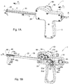
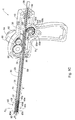
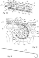
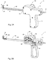
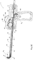
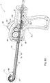
- FIG. 1A to 1F Reference is first made to Figs. 1A to 1F , 2A to 2F and 3A to 3F in order to describe an apparatus 1 and its manner of operation, in accordance with one example of the presently disclosed subject matter.
- the apparatus 1 is a drill which is configured for advancement along a predetermined curved trajectory. It is appreciated that the apparatus of the presently disclosed subject matter according to its different aspects can have applications other than drilling, and drilling is only one of them.
- the apparatus 1 comprises the following components: a housing 10, a conduit 20 extending from the housing 10, an elongated member 30 with a segmented assembly 40, a moving mechanism 60 and a deflecting member 70.
- the operation of the apparatus 1 is such that actuation of the moving mechanism 60 causes the segmented assembly 40 to extend outside from the conduit 20 automatically entailing deflection of the extending part of the segmented assembly 40 by the deflecting member 70 to a predetermined stabilized curved shape.
- actuation of the moving mechanism 60 to cause the segmented assembly 40 to be introduced into the conduit 20 automatically entails the introduced part of the segmented assembly 40 to be straightened within the conduit 20.
- Figs. 1A to 1F illustrate the apparatus 1 with the segmented assembly fully disposed within the conduit 20.
- Figs. 2A to 2F illustrate the apparatus 1 with a part of the segmented assembly 40 extending out of the conduit 20 and having a curved shape.
- Figs. 3A to 3F illustrate the apparatus 1 with the segmented assembly 40 fully extending out of the conduit 20 and having a respective curved shape.
- the housing 10 has a handle 11 shaped so as to fit a hand of an operator of the apparatus 1.
- the conduit 20 has a conduit distal end 22 with an opening and a conduit proximal end 24 connected to the housing 10.
- the conduit distal end 22 and the conduit proximal end 24 extend along an axis X.
- the conduit distal end 22 can be introduced into an aperture of a structure to be treated. If the aperture does not exist, the conduit distal end 22 can be disposed by the operator in proximity to the structure, at a location in which the aperture should be created by the apparatus 1.
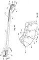
- the elongated member 30 (shown in a detailed manner in Fig. 4A ) extends along the conduit 20 and within the housing 10.
- the elongated member 30 comprises a movable member 35, the segmented assembly 40 and an additional segmented assembly 50.
- the movable member 35 has a first end 37 to which the segmented assembly 40 is pivotally connected and a second end 39 to which the additional segmented assembly 50 is pivotally connected.
- the elongated member 30 has a main axis M defined as an axis extending at the middle of the elongated member 30 along its entire length.
- the housing 10 has a curved channel 12 in which the additional segmented assembly 50 is seated and movable.
- the curved channel 12 has a straight portion 14 and a curved portion 16.
- the curved channel 12 is structured so that the part of the additional segmented assembly 50 which is received within the straight portion 14, is forced to assume a straight shape, and the part of the additional segmented assembly 50 which is received within the curved portion 16 is forced to assume a curved shape.
- the moving mechanism 60 is configured to move the elongated member 30 along the axis X within the conduit 20, for causing a part of the segmented assembly 40 or the entire segmented assembly 40 to extend beyond the conduit distal end 22, and for causing the segmented assembly 40 (as shown, for example, in Figs. 2A and 3A ) to be introduced into the conduit 20 via the conduit distal end 22. Movement of the elongated member 30 also causes the additional segmented assembly 50 to move within the curved channel 12 along the axis M in a respective manner.
- the structure and operation of the moving mechanism 60 is detailed below.
- the moving mechanism 60 is actuated for causing the segmented assembly 40 to extend beyond the conduit distal end 22 while its shape is curved proportionally to its extension beyond the conduit distal end 22.
- the moving mechanism 60 includes a rack and pinion gear constituted by the following components: a rotatable handle 62 mounted to a small circular gear 64 which in turn rotates a large circular gear 66.
- the large circular gear 66 is seated on a linear gear 36 formed in the movable member 35.
- Clockwise rotation of the handle 62 (when seen from the front face of the handle 62), rotates the small circular gear 64 in the same direction, thereby rotating the large circular gear 66 in the anti-clockwise direction, which in turn applies a pushing force on the movable member 35.
- This pushing force causes the segmented assembly 40 to extend beyond the conduit distal end 22.
- Anti-clockwise rotation of the handle 62 causes the segmented assembly 40 to be introduced in the conduit 20 via the conduit distal end 22.
- the moving mechanism 60 can be structured so the when each segment of the segmented assembly 40 escapes from the conduit distal end 22, an audible indication of a "click" is provided to the operator of the apparatus 1. This indication allows the operator to receive information regarding the advancement and the curvature of the part segmented assembly 40 that extends from the conduit 20 and is disposed within the structure. In other words, by hearing each "click", the operator can know what is the length of the part of the segmented assembly that has escaped from the conduit 20, and respectively can know what is the extent of the curvature of this part.
- the segmented assembly 40 is formed of seven segments 40a, 40b, 40c, 40d, 40e, 40f and 40g (shown in Figs 1B , 1C , 1D , 2D and 3D ) that are pivotally connected to each other by pivots.
- the segments 40a and 40b and connected therebetween by a pivot 45a and the segments 40b and 40c and pivotally connected therebetween by a pivot 45b.
- each of the segments 40a, 40b, 40c, 40d, 40e, 40f and 40g has a respective orientation axis N 1 , N 2 , N 3 , N 4 , N 5 , N 6 and N 7 , each being perpendicular to the main axis M.
- the additional segmented assembly 50 is formed of seven segments 50a, 50b, 50c, 50d, 50e, 50f and 50g (shown in Figs 1B , 1C , 1E , 2E and 3E ) that are also pivotally connected to each other by pivots. As shown in Figs. 1E , 2E and 3E , each of the segments 50a, 50b, 50c, 50d, 50e, 50f and 50g has a respective orientation axis N 8 , N 9 , N 10 , N 11 , N 12 , N 13 and N 14 , each being perpendicular to the main axis M. Detailed description of the structure of the above segments is provided below with reference to Figs. 4B to 4E .
- the elongated member 30 has a first channel 32 extending along the main axis M between the most proximal segment 50a of the additional segmented assembly 50 and the most distal segment 40a of the segmented assembly 40 for accommodating the deflecting member 70 therein.
- the deflecting member 70 is an elongated flexible and rigid strip clearly shown in Figs. 1F , 2F and 3F in its different states.
- the deflecting member 70 has a proximal end 72 and a distal end 74.
- the proximal end 72 is seated within a proximal recess 52 formed within the most proximal segment 50a and the distal end 74 is seated within a distal recess 42 formed within the most distal segment 40a.
- the proximal and the distal ends 72 and 74 are not bounded or connected to the segments 50a and 40a so that the deflecting member 70 has a freedom of slight movement within the first channel 32 upon operation of the moving mechanism 60.
- the segmented assembly 40 and the additional segmented assembly 50 constitute an actuator, the role of which is to move the deflecting member 70 within the first channel 32 and to change the shape of the segmented assembly 40 and of the additional segmented assembly 50.
- the role of the deflecting member 70 is to cause the part of the segmented assembly that extends from the conduit distal end 22 to be maximally deflected from a straight to a predetermined curved shape, and to straighten the part of the segmented assembly that is introduced into the conduit 20 via the conduit distal end 22.
- the additional segmented assembly 50 is also drawn in the same direction.
- a similar part of the additional segmented assembly is received within the straight portion 14.
- This causes respective additional segments to pivotally approach each other, thereby shortening the length of a respective part of the first channel 32 by an extension Z (not shown) and causing the most proximal segment 50a to apply a pushing force on the proximal end 72 of the deflecting member 70.
- This pushing force causes the deflecting member 70 to move within the first channel 32 and to apply a pushing force on the most distal segment 40a.
- Z Z 1 +Z 2 +Z 3
- the ability of the respective segments of the part 41 to be pivotally rotated with respect to each other, allows increasing the respective length of the first channel 32 within the part 41 by the extension Z, thereby allowing the moving deflecting member 70 to be received within the longer portion of the first channel 32 while applying the pushing force on the most distal segment 40a.
- the part 41 extends beyond the conduit distal end, while a curved shape thereof is formed.
- Figs. 1D and 1E illustrate an initial position of the elongated member 30, and Figs. 2D and 2E show an advanced position of the elongated member 30 provided as a result of a number of clockwise rotations of the handle 62.
- the entire segmented assembly 40 is located within the conduit 20 and the segmented assembly 40 is in its straight configuration, in which all the segments 40a-40g of the segmented assembly 40 have their orientation axes N 1 -N 7 parallel to each other.
- the segmented assembly 40 is restricted by an internal wall 28 of the conduit 20 to assume the parallel orientation between the axes N 1 -N 7 of the segments 40a-40g.
- the segmented assembly 40 is in its curved configuration in which the part 41 of the segmented assembly 40 extends from the conduit distal end 22.
- the part 41 is constituted by the segments 40a, 40b and 4c.
- the segments 40a, 40b, 40c and 40d are pivotally rotated with respect to each other so that the orientation axes N 1 , N 2 , N 3 and N 4 form angles ⁇ 1 , ⁇ 2 and ⁇ 3 therebetween respectively, so that the part 41 is rendered a curved shape.
- the additional segmented assembly 50 is in its curved configuration in which all the additional segments 50a-50g are disposed in orientation with respect to each other by means of their pivots so that the orientation axes N 8 -N 15 of the corresponding segments and the proximal end 39 form an angle therebetween, so that the entire additional segmented assembly 50 is rendered a curved shape. In this position, the entire additional segmented assembly 50 is located within the curved portion 16.
- a part 51 of the additional segmented assembly 50 is received within the straight portion 14.
- the part 51 is constituted by the segments 50e, 50f and 50g.
- the additional segmented assembly 50 is disposed in its additional curved configuration. In this configuration, the segments 50a, 50b and 50c and the proximal end 39 have their orientation axes N 12 -N 15 parallel to each other.
- the part 41 in Fig. 1D has a length being substantially similar to the length of the part 51 in Fig. 2E
- the part 41 in Fig. 2D has a length being similar to that of part 51 in Fig. 1E .
- the elongated member 30 was moved by the moving mechanism 60 to the respective extent along the axis X.
- the deflecting member 70 is disposed within the part 41 along a portion of the first channel 32 in its first state along a first extension L 1
- the deflecting member 70 is disposed within the part 41 along a portion of the first channel 32 in its second state along a second extension L 2 .
- L 2 is greater than L 1
- the deflecting member 70 is disposed within the part 51 in its additional first state along a portion of the first channel 32 to an additional first extension L 3
- the deflecting member 70 is disposed within the part 51 in its additional second state along a portion of the first channel 32 to an additional second extension L 4 . It can be easily seen from the drawings that L 3 is greater than L 4 .
- the part 41 is drawn from the conduit 30 to extend beyond the conduit distal end 32, allowing the segments 40a to pivotally rotate with respect to the segment 40b, the segment 40b to pivotally rotate with respect to the segment 40c, and the segment 40c to pivotally rotate with respect to the segment 40d.
- the additional segment 50a exerts a pushing force on the proximal end 72. This pushing force causes the deflecting member 70 to move within the first channel 32 along the extension Z, which causes the distal end 74 of the deflecting member 70 to exert a pushing force of the segment 40a.
- Fig. 1F illustrates the shape of the deflecting member 70 in the position of Figs. 1A-1E
- Fig. 2F illustrates the shape of the deflecting member 70 in the position of Figs. 2A-2E . It can be seen from these figures that the shape of the deflecting member 70 corresponds to the shape of the elongated member 30.
- the segmented assembly 40 and the additional segmented assembly 50 switch roles.
- the most distal segment 40a is the one that exerts a pushing force of the deflecting member 70, causing a respective part of the additional segmented assembly 50 to assume its curved shape.
- the segmented assembly plays the role of an actuator.
- the elongated member 30 has a second channel 33 extending along the segmented assembly 40 and the movable member 35.
- the second channel 33 accommodates a rotatable bendable shaft 90 having a proximal end 92 and a distal end 94.
- the proximal end 92 of shaft 90 is received within a rotating element 96 and the distal end 94 is mounted to a rotatable tip 98.
- the rotating element 96 is configured to be rotated manually or automatically by a motor (not shown), thereby causing rotation of the shaft 90, and respective rotation of the tip 98.
- the shaft 90 can be rotated in both the straight and the curved configurations of the segmented assembly 40. This allows providing a conventional straight drilling and drilling along a curved path by a single apparatus.
- FIG. 1A in order to describe the pushing forces applied on the apparatus 1 or components thereof during initiation of its drilling operation and change of configuration from the straight to the curved configuration.
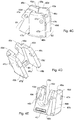
- Figs. 2D and 4A to 4E illustrate the segments of the elongated member 30 and in particular their structure.
- the segments of the segmented assembly 40 and the additional segments of the additional segmented assembly 50 have a similar structure, and therefore, the explanation below is made with respect to the segments of the segmented assembly 40, although it is also relevant for the additional segments of the additional segmented assembly 50.
- the segmented assembly 40 when in its curved configuration has a concave side 44 and a convex side 46.
- the pivots (e.g., the pivots 45a and 45b) of the segmented assembly 40 are disposed closer to the concave side 44 than the deflecting member 70.
- the pivots are disposed in proximity to the concave side 44 and the deflecting member 70 is disposed in proximity to the convex side 46.
- This structure allows exerting a pushing force by the deflecting member 70 at the distal end of the segmented assembly, which is directed from the convex side 46 towards the concave side 44 and is initiated closer to the convex side 46.
- This force is schematically shown in Fig. 2D . This force is much more effective than if the segmented assembly 40 would have been curved by a pulling force applied on the most distal segment 40a and initiated closer to the concave side 44.
- the curved shape of the part 41 of the segmented assembly 40 is an arc characterized by a center of curvature O facing the concave side 44 and a radius R defined between the main axis M and the center of curvature O.
- the pivots of the part 41 are equally spaced from the center of curvature O to a first distance D1 and the deflecting member 70 which extends along the first channel 32 is spaced from the center of curvature O to a second distance D2 and the following condition is fulfilled: D1 ⁇ R ⁇ D2.
- each pair of the adjacent segments has stabilizing portions 80 configured to engage each other in both the straight and the curved configurations of the segmented assembly 40 so as to resist torsion of the adjacent segments with respect to each other.
- the stabilizing portions 80 are disposed closer to the convex side 46 than the concave side 44.
- the stabilizing portions 80 are constituted by a projecting portion 81 of one segment and a recessed portion 82 of its adjacent segment, configured to receive the projecting portion 81.
- Detailed explanation regarding the structure of the stabilizing portions 80 is provided below with respect to a single segment.
- the segment 40d has the following portions: an aperture 43 constituting a part of the second channel 33; an inner segment face 48a constituting a part of the concave side 44; an outer segment face 48b opposite thereto, constituting a part of the convex side 46; first and second opposite outer wings 49a and 49b, defining the recessed portion 82, respectively extending between the inner segment face 48a and the outer segment face 48b; and first and second opposite inner wings 49c and 49d, constituting the projecting portion 81, respectively extending between the inner segment face 48a and the outer segment face 48b.
- the first and second inner wings 49c and 49d of one segment are configured to be received and pivotally movable within the recessed portion 82 formed between the first and second outer wings 49a and 49b of its adjacent segment, thereby forming the segmented assembly and allowing the segmented assembly to change its configuration.
- connection between two adjacent segments is such that the first outer wing 49a of one segment is pivotally connected to the first inner wing 49c of its adjacent segment and the second outer wing 49b of said one segment is pivotally connected to the first inner wing 49d of the adjacent segment.
- the first outer wing 49a comprises the following four surfaces: a first front contact surface 46a; a second front contact surface 46b; a first rear contact surface 46c and a second rear contact surface 46d.
- the second outer wing 49b comprises the following four surfaces: a first front contact surface 47a; a second front contact surface 47b; a first rear contact surface 47c and a second rear contact surface 47d.
- the second rear contact surfaces 46d and 47d of one segment contact the second front contact surfaces 46b and 47b of its adjacent segment, thereby providing a contact surface between the two adjacent segments in addition to the hinges therebetween.
- the first front contact surfaces 46a and 47b of one segment contact the first rear contact surfaces 46c and 47c of its adjacent segment, thereby delimiting the deflection of these segments with respect to each other to a predefined extent.
- the contact between segments of the part 41 allows also transferring the pushing force exerted on the most distal segment 40a to at least one of its successive segments for causing them to form an angle between orientation axes of the adjacent segments.
- the location of the first front contact surfaces 46a and 47b and the first rear contact surfaces 46c and 47c with respect to each other defines the angle between the orientation axes of two adjacent segments. For example, this location defines the value of the angles ⁇ 1 , ⁇ 2 and ⁇ 3 .
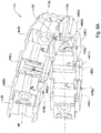
- the segmented assembly 140 has two first channels 132, each with a deflecting member 170.
- the deflecting members 170 are elongated flexible and rigid shafts.
- the deflecting members 170 have functionality which is similar to that of the deflecting member 70.
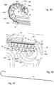
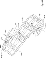
- Figs. 6A to 6C in which another example of a segmented assembly 240 in accordance with the presently disclosed subject matter is shown.
- the segmented assembly 240 has a channel 232 with a deflecting member 270 received therein.
- the deflecting member 270 is a roller chain formed of a plurality of rigid segments 272 pivotally connected therebetween.
- the deflecting member 270 has functionally which is similar to that of the deflecting member 70.
- each of the segments 272 is non-bendable and thus is able to efficiently transfer pushing forces exerted therealong, and on the other the entire deflecting member 270 is able to be bent as required for deflecting the segmented assembly 240.
- Figs. 7A and 7B in which another example of a segmented assembly 340 in accordance with the presently disclosed subject matter is shown.
- the segmented assembly 340 is constructed of segments 340a-340j.
- the segments 340a-340j are hingedly connected to each other by effective hinges 341a-341j that are integrally formed as connecting portions of flexible material interconnecting between each pair of segments.
- the segmented assembly 340 has a first channel 332 extending along a deflecting member 370.
- Fig. 7A the segmented assembly 340 is shown in its straight configuration
- Fig. 7B the segmented assembly 340 is shown in its curved configuration.
- the segmented assembly 340 when in its curved configuration has a concave side 344 and a convex side 346.
- the hinges 341a-341j of the segmented assembly 340 are disposed closer to the concave side 344 than the deflecting member 370.
- the hinges 341a-341j are disposed in proximity to the concave side 344 and the deflecting member 370 is disposed in proximity to the convex side 346.
- This structure allows exerting a pushing force F' by the deflecting member 370 at a most distal segment 340a, which is directed from the convex side 346 towards the concave side 344 and is initiated closer to the convex side 346.
- This force is much more effective than if the segmented assembly 340 would have been curved by a pulling force applied of the most distal segment 340a and initiated closer to the concave side 344.
- the curved shape of the segmented assembly 340 is an arc characterized by a center of curvature O' facing the concave side 344 and a radius R' defined between a main axis M' of the segmented assembly 340 and the center of curvature O'.
- the hinges 341a-341j are equally spaced from the center of curvature O' to a first distance D1' and the deflecting member 370 extending along the first channel 332 is spaced from the center of curvature O' to a second distance D2' and the following condition is fulfilled: D1' ⁇ R' ⁇ D2'.
- the segmented assembly 340 further has a strip 380 disposed at the convex side 346.
- the strip 380 connects two adjacent segments of the segmented assembly 340 so as to limit their rotatable movement with respect to each other to a predetermined extent.
- a segmented assembly 440 is shown as a three dimensional helix.
- the segmented assembly 440 has a longitudinal axis M" main axis along which it extends.
- the segmented assembly 440 is formed of eight segments 440a, 440b, 440c, 440d, 440e, 440f, 440g, 440h and 440i that are pivotally connected to each other by respective pivots 445a, 445b, 445c, 445d, 445e, 445f, 445g and 445h.
- Each one of the pivots has a pivot axis P 1 , P 2 , P 3 , P 4 , P 5 , P 6 , P 7 and P 8 .
- Each one of the pivots Pi-Ps is angled with respect to the main axis M" at obtuse angle which is slightly greater than 90 degrees). According to the present example, this angle is identical with respect to each one of the pivots P 1 -P 8 . The value of this angle defines the extension of the segmented assembly 440 along the main axis M", and in particular, the spacing between the coils thereof.
- the segmented assembly 440 of the above described helix shape can be used for lifting a part of the structure or for three dimensional advancement therein.
Landscapes
- Health & Medical Sciences (AREA)
- Engineering & Computer Science (AREA)
- Life Sciences & Earth Sciences (AREA)
- General Engineering & Computer Science (AREA)
- Surgery (AREA)
- Mechanical Engineering (AREA)
- Veterinary Medicine (AREA)
- Public Health (AREA)
- General Health & Medical Sciences (AREA)
- Animal Behavior & Ethology (AREA)
- Nuclear Medicine, Radiotherapy & Molecular Imaging (AREA)
- Biomedical Technology (AREA)
- Heart & Thoracic Surgery (AREA)
- Medical Informatics (AREA)
- Molecular Biology (AREA)
- Optics & Photonics (AREA)
- Radiology & Medical Imaging (AREA)
- Pathology (AREA)
- Biophysics (AREA)
- Physics & Mathematics (AREA)
- Rehabilitation Therapy (AREA)
- Oral & Maxillofacial Surgery (AREA)
- Surgical Instruments (AREA)
- Media Introduction/Drainage Providing Device (AREA)
- Drilling And Boring (AREA)
- Perforating, Stamping-Out Or Severing By Means Other Than Cutting (AREA)
- Processing Of Stones Or Stones Resemblance Materials (AREA)
Claims (13)
- Appareil (1) capable d'avancer le long d'une trajectoire incurvée prédéterminée, comprenant :a. un conduit (20) ayant une extrémité distale de conduit (22) ;b. un élément allongé (30) ayant un axe principal (M), s'étendant au moins partiellement à l'intérieur dudit conduit (20) et mobile à l'intérieur de celui-ci le long de sa longueur, ledit élément allongé (30) comprenant :un élément mobile (35) ayant une première extrémité (37) et une seconde extrémité (39) ;un ensemble segmenté (40) relié à la première extrémité (37) et formé d'une pluralité de segments (40a-40g) articulés l'un sur l'autre, chacun ayant un axe d'orientation (N1-N7) perpendiculaire à l'axe principal (M), et ;un ensemble segmenté supplémentaire (50) relié à la seconde extrémité (39) et formé d'une pluralité de segments supplémentaires (50a-50g) articulés l'un sur l'autre, chacun ayant un axe d'orientation (N8-N15) perpendiculaire à l'axe principal (M) ;c. un élément de déviation (70) s'étendant le long dudit axe principal (M) de manière à présenter :(i) un premier état comportant une première extension (L1) le long d'au moins une partie (41) de l'ensemble segmenté (40) comprenant son segment le plus distal (40a), et un second état comportant une seconde extension (L2) le long de ladite partie (41) de l'ensemble segmenté (40), la seconde extension (L2) dépassant la première extension (L1) ;
ledit élément de déviation (70) ayant une extrémité distale (74) mécaniquement associée au moins audit segment le plus distal (40a) dudit ensemble segmenté (40) de manière à permettre à ladite extrémité distale (74) d'exercer une force de poussée sur au moins ledit segment le plus distal (40a) au moins lorsque l'élément de déviation (70) change d'état, passant du premier au second état ;
ledit ensemble segmenté (40) étant conçu pour changer de configuration, au moins lorsque ladite force de poussée est exercée, d'une configuration droite associée audit premier état de l'élément de déviation (70), état dans lequel les axes d'orientation (N1-N7) de tous les segments sont parallèles les uns aux autres, à une configuration incurvée associée audit second état de l'élément de déviation (70), état dans lequel au moins ladite partie (41) de l'ensemble segmenté (40) s'étend au-delà de ladite extrémité distale de conduit (22) et les segments correspondants (40a-40g) de ladite partie (41) changent d'orientation (N1-N7) les uns par rapport aux autres au moyen de leurs articulations, de sorte que les axes d'orientation des segments correspondants forment un angle entre eux (α1-α3), et de sorte que ladite partie (41) de l'ensemble (40) prenne une forme incurvée ; et(ii) un premier état supplémentaire comportant une première extension supplémentaire (L3) le long d'au moins une partie (51) de l'ensemble segmenté supplémentaire (50) comprenant son segment le plus proximal (50a), et un second état supplémentaire comportant une seconde extension supplémentaire (L4) le long de ladite partie (51) de l'ensemble segmenté supplémentaire (50) ; ladite première extension supplémentaire (L3) dépassant la seconde extension supplémentaire (L4) ;
ledit élément de déviation (70) ayant une extrémité proximale (72) mécaniquement associée au moins audit segment le plus proximal (50a) dudit ensemble segmenté supplémentaire (50) de manière à permettre audit segment extrême proximal (50a) d'exercer une force de poussée sur l'extrémité proximale (72) au moins lorsque l'élément de déviation (70) change d'état, passant du premier état supplémentaire au second état supplémentaire ;
l'ensemble segmenté supplémentaire (50) étant conçu pour changer de configuration, au moins lorsque ladite force de poussée sur ladite extrémité proximale (72) est exercée, passant d'une configuration incurvée supplémentaire associée audit premier état supplémentaire de l'élément de déviation (70), état dans lequel tous les segments supplémentaires (50a-50g) sont disposés en orientation les uns par rapport aux autres au moyen de leurs articulations, de sorte que les axes d'orientation (N8-N15) des segments correspondants (50a-50g) forment un angle entre eux, à une configuration droite supplémentaire associée audit second état supplémentaire de l'élément de déviation (70), état dans lequel les axes d'orientation (N8-N15) des segments (50a-50g) de la partie (51) de l'ensemble segmenté supplémentaire (50) sont parallèles les uns aux autres,
l'élément de déviation (70) adopte le premier état comportant le premier état supplémentaire, et le second état comportant le second état supplémentaire ;d. un mécanisme de déplacement (60) conçu pour appliquer une force de poussée sur l'élément allongé (30) afin de déplacer l'élément allongé (30) le long du conduit (20) et d'amener la partie (41) de l'ensemble segmenté (40) à s'étendre au-delà de l'extrémité distale (22) du conduit et à être introduite dans le conduit (20) par l'intermédiaire de l'extrémité distale (22) du conduit ; ete. un actionneur étant mécaniquement associé à l'élément de déviation (70) et conçu pour déplacer l'élément de déviation (70) le long dudit axe principal (M) et le faire passer du premier au second état,
ledit mécanisme de déplacement (60) étant mécaniquement associé à l'actionneur, de sorte que le fonctionnement du mécanisme de déplacement (60) pour déplacer l'élément allongé (30) le long du conduit (20) implique le fonctionnement de l'actionneur pour déplacer l'élément de déviation (70) dans la même direction, facilitant ainsi le mouvement de l'élément allongé (30) dans cette direction ;
ledit ensemble segmenté (40) et l'ensemble segmenté supplémentaire (50) constituant l'actionneur. - Appareil (1) selon la revendication 1, dans lequel l'extrémité distale (74) de l'élément de déviation (70) est en outre associée mécaniquement au segment le plus distal (40a), de manière à permettre au segment le plus distal (40a) d'exercer une force de poussée sur l'extrémité distale (74) au moins lorsque la partie (41) de l'ensemble segmenté (40) est introduite dans le conduit (20) par l'intermédiaire de l'extrémité distale (22) du conduit et que l'ensemble segmenté (40) change de configuration, passant de la configuration incurvée à la configuration droite, changeant ainsi l'état de l'élément de déviation (70), du second au premier état.
- Appareil (1) selon la revendication 1, dans lequel l'actionneur est constitué par l'ensemble segmenté (40) et par l'ensemble segmenté supplémentaire (50) de sorte que :le fonctionnement du mécanisme de déplacement (60) pour déplacer l'élément allongé (30) le long du conduit (20) de manière à ce que ledit ensemble segmenté (40) s'étende à partir de l'extrémité distale de conduit (22), implique que l'ensemble segmenté supplémentaire (50) change de configuration, passant de la configuration incurvée supplémentaire à la configuration droite supplémentaire, ce qui implique que le segment extrême proximal (50a) de l'ensemble segmenté supplémentaire (50) exerce une force de poussée sur l'extrémité proximale (72) de l'élément de déviation (70), l'amenant à se déplacer dans la même direction et à changer d'état, passant du premier au second état, modifiant ainsi la configuration de l'ensemble segmenté (40), de la configuration droite à la configuration incurvée ; etle fonctionnement du mécanisme de déplacement (60) pour déplacer l'élément allongé (30) le long du conduit (20) de manière à provoquer l'introduction dudit ensemble segmenté (40) dans le conduit (20) par l'intermédiaire de l'extrémité distale de conduit (22), implique que l'ensemble segmenté (40) change de configuration, passant de la configuration incurvée à la configuration droite, ce qui implique que le segment le plus distal (40a) exerce une force de poussée sur l'extrémité distale (74) de l'élément de déviation (70), l'amenant à se déplacer dans la même direction et à changer d'état, passant du second état supplémentaire au premier état supplémentaire, modifiant ainsi la configuration de l'ensemble segmenté supplémentaire (50), de la configuration droite supplémentaire à la configuration incurvée supplémentaire.
- Appareil (1) selon l'une quelconque des revendications précédentes, comprenant un boîtier ayant un canal incurvé (12), le canal incurvé (12) ayant une partie droite (14) s'étendant le long du conduit (20) pour accueillir une partie de l'ensemble segmenté supplémentaire (50), lorsqu'elle se trouve dans sa configuration droite supplémentaire, et une partie incurvée (16) destinée à accueillir la partie de l'ensemble segmenté supplémentaire (50), lorsqu'elle se trouve dans la configuration incurvée supplémentaire, ledit ensemble segmenté supplémentaire (50) étant mobile dans le canal incurvé (12), entre sa configuration droite supplémentaire et sa configuration incurvée supplémentaire.
- Appareil selon l'une quelconque des revendications précédentes, dans lequel ledit ensemble segmenté (40), lorsqu'il est dans sa configuration incurvée, a un côté concave (44) et un côté convexe (46) ; au moins dans une majorité des segments, chaque paire de segments adjacents ayant des parties stabilisatrices (80) plus proches du côté convexe (46) que du côté concave (44) et étant autres que la connexion articulée entre elles, lesdites parties stabilisatrices (80) étant conçues pour entrer en prise les unes avec les autres à la fois dans les configurations droite et incurvée de l'ensemble segmenté (40), de manière à résister à la torsion des segments adjacents l'un par rapport à l'autre.
- Appareil selon la revendication 5, dans lequel lesdites parties stabilisatrices (80) sont constituées par une partie en saillie (81) d'un segment et une partie en retrait (82) de son segment adjacent, laquelle partie en retrait est conçue pour recevoir ladite partie en saillie (41) ; les articulations (341a-341j) étant disposées à proximité du côté concave (44) et l'élément de déviation (70) étant disposé à proximité du côté convexe (46), et la forme incurvée étant un arc caractérisé par un centre de courbure (O) faisant face au côté concave (44) et un rayon (R) défini entre l'axe principal (M) et le centre de courbure (O), les articulations (341a-341j) de la partie de l'ensemble segmenté (40) étant également espacées dudit centre de courbure (O) d'une première distance (D1), et l'élément de déviation (70) s'étendant le long d'un premier canal (32) formé dans l'élément allongé, ledit premier canal étant espacé dudit centre de courbure (O) d'une seconde distance (D2) et la condition suivante étant remplie : D1<R<D2.
- Appareil selon la revendication 6, dans lequel chaque segment d'au moins une majorité desdits segments (40a-40g) comprend : une face de segment interne (48a) constituant une partie du côté concave (44) ; une face de segment externe (48b) opposée à celle-ci, constituant une partie du côté convexe (46) ; des première et seconde ailes externes opposées (49a, 49b), constituant au moins une partie de la partie en retrait (82), s'étendant respectivement entre la face de segment interne (48a) et la face de segment externe (48b) entre elles ; et des première et seconde ailes internes opposées (49a, 49b), constituant au moins une partie de la partie en saillie (81), s'étendant respectivement entre la face de segment interne (48a) et la face de segment externe (48b) ; lesdites première et seconde ailes internes (49a, 49b) d'un segment étant reçues et mobiles par articulation à l'intérieur de ladite partie en retrait (82) formée entre lesdites première et seconde ailes externes (49a, 49b) de son segment adjacent, formant ainsi ledit ensemble segmenté (40) et permettant à l'ensemble segmenté (40) de changer de configuration.
- Appareil selon la revendication 7, dans lequel la connexion entre deux segments adjacents est telle que la première aile externe (49a) d'un segment est reliée de façon pivotante à la première aile interne (49c) de son segment adjacent, et la seconde aile externe (49b) dudit segment est reliée de façon pivotante à la première aile interne (49d) du segment adjacent.
- Appareil selon la revendication 7 ou 8, dans lequel chacune des première et seconde ailes externes (49a, 49b) comprend : une première surface de contact avant (46a, 47a) ; une seconde surface de contact avant (46b, 47b) ; une première surface de contact arrière (46c, 47c) et une seconde surface de contact arrière (46d, 47d), de sorte que dans la configuration droite, les secondes surfaces de contact arrière (46d, 47d) d'un segment sont en contact avec les secondes surfaces de contact avant (46b, 47b) de son segment adjacent, fournissant ainsi une surface de contact entre les deux segments adjacents en plus des articulations entre eux, et que, dans la configuration incurvée, les premières surfaces de contact avant (46a, 47a) d'un segment entrent en contact avec les premières surfaces de contact arrière (46c, 47d) de son segment adjacent, délimitant ainsi la déviation de ces segments les uns par rapport aux autres dans une mesure prédéfinie et transférant la force de poussée du segment extrême distal (40a) à au moins l'un de ses segments successifs pour les amener à former un angle entre les axes d'orientation des segments adjacents.
- Appareil selon la revendication 9, dans lequel l'application de la force de poussée par le mécanisme de déplacement (60) transfère cette force entre deux segments disposés en ligne droite l'un par rapport à l'autre par le contact entre les secondes surfaces de contact avant (46b, 47b) d'un segment avec les secondes surfaces de contact arrière (46d), 47d) de son segment adjacent, en plus des articulations entre eux, et entre deux segments dont les axes d'orientation forment un angle, par contact des premières surfaces de contact avant (46a, 47a) d'un segment avec les premières surfaces de contact arrière (46c, 47c) de son segment adjacent, en plus des articulations entre eux.
- Appareil selon la revendication 6, dans lequel chacun desdits segments comprend un second canal (33) conçu pour permettre le passage d'un outil de travail à travers l'élément allongé (30).
- Procédé non chirurgical de fonctionnement d'un appareil capable d'avancer le long d'une trajectoire incurvée prédéterminée, le procédé comprenant les étapes suivantes :a. obtention d'un appareil selon l'une des revendications 1 à 11 ;b. déplacement dudit élément allongé (30) le long du conduit (20) de manière à faire en sorte qu'au moins ladite partie (41) de l'ensemble segmenté (40) s'étende au-delà de ladite extrémité distale de conduit (22) ;c. changement de l'état de l'élément de déviation (70), du premier au second état, amenant ainsi ladite extrémité distale (74) de l'élément de déviation (70) à exercer une force de poussée sur au moins ledit segment le plus distal (40a) ; etd. le fait d'amener l'ensemble segmenté (40), au moins au moyen de ladite force de poussée, à passer d'une configuration droite associée audit premier état de l'élément de déviation (70), configuration dans laquelle les axes d'orientation (N1-N7) de tous les segments (40a-40g) sont parallèles les uns aux autres, à une configuration incurvée associée audit second état de l'élément de déviation (70), configuration dans laquelle au moins ladite partie (41) de l'ensemble segmenté (40) s'étend au-delà de ladite extrémité distale (22) du conduit et les segments correspondants (40a-40g) de ladite partie (41) changent leur orientation les uns par rapport aux autres au moyen de leurs articulations, de sorte que les axes d'orientation (N1-N7) des segments correspondants (40a-40g), rendant ainsi ladite partie (41) de l'ensemble segmenté (40) une forme incurvée.
- Procédé non chirurgical selon la revendication 12, comprenant en outre une étape de déplacement dudit élément allongé (30) le long du conduit (20) de manière à entraîner l'introduction d'au moins ladite partie (41) de l'ensemble segmenté (40) dans l'extrémité distale (22) du conduit, amenant ainsi le segment le plus distal (40a) à exercer une force de poussée sur l'extrémité distale (74) au moins lorsque la partie (41) de l'ensemble segmenté (40), changeant l'état de l'élément de déviation (70) du second état au premier état et permettant à l'ensemble segmenté (40) de changer de configuration, passant de la configuration incurvée à la configuration droite.
Applications Claiming Priority (2)
| Application Number | Priority Date | Filing Date | Title |
|---|---|---|---|
| IL231054A IL231054A (en) | 2014-02-20 | 2014-02-20 | A device for advancing along a curved track and a method for its operation |
| PCT/IL2015/050186 WO2015125140A1 (fr) | 2014-02-20 | 2015-02-18 | Appareil d'avancée le long d'une trajectoire incurvée prédéterminée, et son procédé de fonctionnement |
Publications (3)
| Publication Number | Publication Date |
|---|---|
| EP3107441A1 EP3107441A1 (fr) | 2016-12-28 |
| EP3107441A4 EP3107441A4 (fr) | 2018-02-14 |
| EP3107441B1 true EP3107441B1 (fr) | 2020-09-23 |
Family
ID=51691277
Family Applications (1)
| Application Number | Title | Priority Date | Filing Date |
|---|---|---|---|
| EP15752740.9A Not-in-force EP3107441B1 (fr) | 2014-02-20 | 2015-02-18 | Appareil capable d'avancer le long d'une trajectoire incurvée prédéterminée, et son procédé de fonctionnement |
Country Status (8)
| Country | Link |
|---|---|
| US (1) | US10591029B2 (fr) |
| EP (1) | EP3107441B1 (fr) |
| JP (1) | JP2017515517A (fr) |
| KR (1) | KR20160123362A (fr) |
| CN (1) | CN106061363A (fr) |
| CA (1) | CA2939863C (fr) |
| IL (1) | IL231054A (fr) |
| WO (1) | WO2015125140A1 (fr) |
Families Citing this family (30)
| Publication number | Priority date | Publication date | Assignee | Title |
|---|---|---|---|---|
| US10405936B2 (en) | 2008-04-11 | 2019-09-10 | The Regents Of The University Of Michigan | Parallel kinematic mechanisms with decoupled rotational motions |
| US9629689B2 (en) | 2008-04-11 | 2017-04-25 | Flexdex, Inc. | Attachment apparatus for remote access tools |
| US9869339B2 (en) | 2008-04-11 | 2018-01-16 | Flexdex, Inc. | End-effector jaw closure transmission systems for remote access tools |
| IL231054A (en) | 2014-02-20 | 2015-07-30 | Tzony Siegal | A device for advancing along a curved track and a method for its operation |
| EP3282952B1 (fr) | 2015-04-03 | 2019-12-25 | The Regents Of The University Of Michigan | Appareil de gestion de la tension pour transmission entraînée par câble |
| US10624617B2 (en) | 2015-05-27 | 2020-04-21 | Ambu A/S | Endoscope |
| US10617284B2 (en) | 2015-05-27 | 2020-04-14 | Ambu A/S | Endoscope |
| EP3302217B1 (fr) | 2015-05-27 | 2020-06-03 | Ambu A/S | Endoscope |
| WO2016188539A1 (fr) | 2015-05-27 | 2016-12-01 | Ambu A/S | Endoscope |
| EP3302214B1 (fr) | 2015-05-27 | 2019-07-31 | Ambu A/S | Endoscope comprenant un châssis à structure de coque |
| WO2016188543A1 (fr) * | 2015-05-27 | 2016-12-01 | Ambu A/S | Endoscope à outil |
| EP3302213B1 (fr) | 2015-05-27 | 2022-11-23 | Ambu A/S | Endoscope |
| JP6887997B2 (ja) | 2015-10-02 | 2021-06-16 | フレックスデックス, インク.Flexdex, Inc. | 無制限ロールを付与するハンドル機構 |
| US12594069B2 (en) | 2015-10-02 | 2026-04-07 | Livsmed, Inc. | Handle assembly providing unlimited roll |
| US11896255B2 (en) | 2015-10-05 | 2024-02-13 | Flexdex, Inc. | End-effector jaw closure transmission systems for remote access tools |
| US10959797B2 (en) | 2015-10-05 | 2021-03-30 | Flexdex, Inc. | Medical devices having smoothly articulating multi-cluster joints |
| CN209548018U (zh) | 2016-02-25 | 2019-10-29 | 弗莱克斯德克斯公司 | 并联运动机构 |
| US10610345B2 (en) | 2016-09-21 | 2020-04-07 | Ethicon, Inc. | Applicator instruments for dispensing surgical fasteners having articulating shafts |
| CN107157554A (zh) * | 2017-06-26 | 2017-09-15 | 内江市市中区人民医院 | 一种经皮椎体成形术定位用穿刺针及穿刺装置 |
| WO2019038863A1 (fr) * | 2017-08-23 | 2019-02-28 | オリンパス株式会社 | Outil de traitement |
| DE102018104768A1 (de) * | 2018-03-02 | 2019-09-05 | Iwis Antriebssysteme Gmbh & Co. Kg | Aktuator mit rückensteifer Kette |
| GB2576039B (en) * | 2018-08-02 | 2021-01-06 | Ip2Ipo Innovations Ltd | A joint |
| US12239322B2 (en) | 2018-08-17 | 2025-03-04 | Empress Medical, Inc. | Device and method for passing tension member around tissue mass |
| US11419610B2 (en) | 2018-08-17 | 2022-08-23 | Empress Medical, Inc. | Device and method for passing tension member around tissue mass |
| CN112770680A (zh) | 2018-08-17 | 2021-05-07 | 安普列斯医疗公司 | 用于压迫肿瘤的装置和方法 |
| US10918833B2 (en) * | 2018-09-26 | 2021-02-16 | Freudenberg Medical, Llc | Modular handle assembly for a steerable catheter |
| KR102850369B1 (ko) * | 2020-05-08 | 2025-08-27 | 엘지전자 주식회사 | 커피 메이커 |
| US11950966B2 (en) | 2020-06-02 | 2024-04-09 | Flexdex, Inc. | Surgical tool and assembly |
| US20230100909A1 (en) * | 2021-08-27 | 2023-03-30 | Michael Peck | Sequential stylet |
| USD1105427S1 (en) | 2023-04-14 | 2025-12-09 | Flexdex, Inc. | Handheld laparoscopic surgical instrument |
Family Cites Families (32)
| Publication number | Priority date | Publication date | Assignee | Title |
|---|---|---|---|---|
| US5762067A (en) * | 1996-05-30 | 1998-06-09 | Advanced Technology Laboratories, Inc. | Ultrasonic endoscopic probe |
| DE19608809C2 (de) * | 1996-03-07 | 1998-04-09 | Karlsruhe Forschzent | Instrument für die minimal invasive Chirurgie |
| CN1870930A (zh) * | 2003-08-20 | 2006-11-29 | 新引导系统公司 | 活化聚合物关节连接的器械及插入方法 |
| WO2006026520A2 (fr) * | 2004-08-31 | 2006-03-09 | Surgical Solutions Llc | Dispositif medical a arbre articule |
| US7811277B2 (en) * | 2004-09-30 | 2010-10-12 | Boston Scientific Scimed, Inc. | Steerable device and system |
| EP2633829B1 (fr) * | 2005-01-05 | 2015-12-09 | NLT Spine Ltd. | Dispositif d'introduction dans un corps le long d'une structure limitative sensiblement droite |
| US8679097B2 (en) * | 2005-12-20 | 2014-03-25 | Orthodynamix Llc | Method and devices for minimally invasive arthroscopic procedures |
| US20070219550A1 (en) * | 2006-01-27 | 2007-09-20 | Mark Thompson | Device and system for surgical dissection and/or guidance of other medical devices into body |
| EP2024259B1 (fr) * | 2006-06-08 | 2019-08-21 | Bannerman, Brett | Dispositif medical a tige articulee |
| CA2664167A1 (fr) * | 2006-10-06 | 2008-04-17 | Tyco Healthcare Group Lp | Dispositif endoscopique de suture et de separation de vaisseaux ayant un arbre d'articulation souple |
| US8021429B2 (en) * | 2007-03-08 | 2011-09-20 | Zimmer Spine, Inc. | Deployable segmented TLIF device |
| US8137263B2 (en) * | 2007-08-24 | 2012-03-20 | Karl Storz Endovision, Inc. | Articulating endoscope instrument |
| US8287469B2 (en) * | 2008-01-09 | 2012-10-16 | Ethicon Endo-Surgery, Inc. | Articulating surgical device and method of use |
| US8328812B2 (en) * | 2008-07-27 | 2012-12-11 | NLT-Spine Ltd. | Tool and corresponding method for removal of material from within a body |
| GB0813990D0 (en) * | 2008-07-31 | 2008-09-10 | Surgical Innovations Ltd | Endoscopic surgical instrument |
| US20100249497A1 (en) * | 2009-03-30 | 2010-09-30 | Peine William J | Surgical instrument |
| US20100280526A1 (en) * | 2009-04-29 | 2010-11-04 | Arch Day Design, Llc | Medical Device With Articulating Shaft Mechanism |
| DE102009042491A1 (de) * | 2009-05-29 | 2010-12-02 | Aesculap Ag | Chirurgisches Instrument |
| US8523844B2 (en) * | 2009-10-30 | 2013-09-03 | Covidien Lp | Surgical instrument with tendon preload-and-locking device |
| US8403945B2 (en) * | 2010-02-25 | 2013-03-26 | Covidien Lp | Articulating endoscopic surgical clip applier |
| US8403832B2 (en) * | 2010-02-26 | 2013-03-26 | Covidien Lp | Drive mechanism for articulation of a surgical instrument |
| US8439912B2 (en) * | 2010-02-26 | 2013-05-14 | Covidien Lp | De-tensioning mechanism for articulation drive cables |
| US9877720B2 (en) * | 2010-09-24 | 2018-01-30 | Ethicon Llc | Control features for articulating surgical device |
| EP2618767A4 (fr) * | 2010-09-24 | 2017-11-08 | ArthroCare Corporation | Systèmes, dispositifs et procédés permettant de fournir une thérapie à une structure anatomique à l'aide d'ondes de pression en haute fréquence et/ou de températures cryogéniques |
| US20120109186A1 (en) * | 2010-10-29 | 2012-05-03 | Parrott David A | Articulating laparoscopic surgical instruments |
| WO2013018062A1 (fr) * | 2011-08-02 | 2013-02-07 | Nlt Spine Ltd. | Vis osseuse avec partie déformable |
| US8968312B2 (en) * | 2011-11-16 | 2015-03-03 | Covidien Lp | Surgical device with powered articulation wrist rotation |
| DE102012208605A1 (de) * | 2012-05-23 | 2013-11-28 | Karl Storz Gmbh & Co. Kg | Medizinisches Instrument mit einem Schaft mit einem flexiblen Abschnitt und einem gesteuert krümmbaren Abschnitt |
| US9011429B2 (en) * | 2012-06-07 | 2015-04-21 | Smith & Nephew, Inc. | Flexible probe with adjustable tip |
| US10029073B2 (en) * | 2012-11-13 | 2018-07-24 | Abbott Cardiovascular Systems, Inc. | Steerable assembly for surgical catheter |
| WO2014162511A1 (fr) * | 2013-04-02 | 2014-10-09 | カール シュトルツ ゲゼルシャフト ミット ベシュレンクテル ハフツング ウント コンパニー コマンディートゲゼルシャフト | Manipulateur médical |
| IL231054A (en) | 2014-02-20 | 2015-07-30 | Tzony Siegal | A device for advancing along a curved track and a method for its operation |
-
2014
- 2014-02-20 IL IL231054A patent/IL231054A/en active IP Right Grant
-
2015
- 2015-02-18 CN CN201580009396.9A patent/CN106061363A/zh active Pending
- 2015-02-18 EP EP15752740.9A patent/EP3107441B1/fr not_active Not-in-force
- 2015-02-18 CA CA2939863A patent/CA2939863C/fr active Active
- 2015-02-18 KR KR1020167025480A patent/KR20160123362A/ko not_active Withdrawn
- 2015-02-18 JP JP2016552309A patent/JP2017515517A/ja active Pending
- 2015-02-18 WO PCT/IL2015/050186 patent/WO2015125140A1/fr not_active Ceased
- 2015-02-18 US US15/118,899 patent/US10591029B2/en active Active
Non-Patent Citations (1)
| Title |
|---|
| None * |
Also Published As
| Publication number | Publication date |
|---|---|
| CA2939863C (fr) | 2023-10-17 |
| IL231054A0 (en) | 2014-09-30 |
| CA2939863A1 (fr) | 2015-08-27 |
| JP2017515517A (ja) | 2017-06-15 |
| WO2015125140A1 (fr) | 2015-08-27 |
| KR20160123362A (ko) | 2016-10-25 |
| US20160348769A1 (en) | 2016-12-01 |
| EP3107441A1 (fr) | 2016-12-28 |
| EP3107441A4 (fr) | 2018-02-14 |
| CN106061363A (zh) | 2016-10-26 |
| IL231054A (en) | 2015-07-30 |
| US10591029B2 (en) | 2020-03-17 |
Similar Documents
| Publication | Publication Date | Title |
|---|---|---|
| EP3107441B1 (fr) | Appareil capable d'avancer le long d'une trajectoire incurvée prédéterminée, et son procédé de fonctionnement | |
| JP6869256B2 (ja) | 遠位の柔軟性が制御された操向ツール | |
| EP4088668B1 (fr) | Anastomate de coupe linéaire endoscopique pliable et son ensemble | |
| DE4340707C2 (de) | Manipulator | |
| DE69532486T2 (de) | Chirurgisches Instrument | |
| JP6475726B2 (ja) | 器具、特に医療用内視鏡器具又はテクノスコープ | |
| EP1486172B1 (fr) | Instrument chirurgical | |
| JP2020526237A (ja) | 操向可能外科ロボティックシステム | |
| EP1464289A1 (fr) | Instrument chirurgical, dans lequel les mouvements de la tête et de l'outil sont découplés | |
| US20190167368A1 (en) | Medical instrument | |
| DE10330604A1 (de) | Chirurgisches Instrument | |
| WO2013158974A1 (fr) | Poignets habiles pour une intervention chirurgicale | |
| CN107530134A (zh) | 机电手术系统 | |
| RU2018101701A (ru) | Конструкции системы двухшарнирного привода для хирургических инструментов с возможностью шарнирного поворота | |
| DE8535164U1 (de) | Chirurgisches Greifinstrument | |
| DE102016122477A1 (de) | Endoskopkopf und endoskop mit diesem | |
| WO2016034173A1 (fr) | Instrument, en particulier instrument endoscopique à usage médical, ou technoscope | |
| WO2014124846A1 (fr) | Instrument, en particulier instrument médical d'endoscopie ou technoscope | |
| DE102016118158B3 (de) | Biegbares Schaftrohr eines medizinischen Instrumentes, medizinisches Instrument und Verfahren zur Herstellung eines biegbaren Schaftrohres | |
| US11627976B2 (en) | Force transmission mechanism and instrument | |
| US20150173787A1 (en) | Medical Instrument With A Flexible Toothed Belt | |
| CN116983087A (zh) | 手术器械及手术机器人 | |
| KR101821183B1 (ko) | 조향 가능한 카테터를 구비한 의료 장치 | |
| EP2539007B1 (fr) | Dispositif pour observer et/ou manipuler des objets disposés dans une cavité accessible par une ouverture étroite | |
| WO2011037131A1 (fr) | Actionneur à commande à distance et procédé de formage plastique pour élément de commande de position |
Legal Events
| Date | Code | Title | Description |
|---|---|---|---|
| PUAI | Public reference made under article 153(3) epc to a published international application that has entered the european phase |
Free format text: ORIGINAL CODE: 0009012 |
|
| STAA | Information on the status of an ep patent application or granted ep patent |
Free format text: STATUS: REQUEST FOR EXAMINATION WAS MADE |
|
| 17P | Request for examination filed |
Effective date: 20160920 |
|
| AK | Designated contracting states |
Kind code of ref document: A1 Designated state(s): AL AT BE BG CH CY CZ DE DK EE ES FI FR GB GR HR HU IE IS IT LI LT LU LV MC MK MT NL NO PL PT RO RS SE SI SK SM TR |
|
| AX | Request for extension of the european patent |
Extension state: BA ME |
|
| DAX | Request for extension of the european patent (deleted) | ||
| A4 | Supplementary search report drawn up and despatched |
Effective date: 20180112 |
|
| RIC1 | Information provided on ipc code assigned before grant |
Ipc: A61B 1/008 20060101AFI20180108BHEP |
|
| GRAP | Despatch of communication of intention to grant a patent |
Free format text: ORIGINAL CODE: EPIDOSNIGR1 |
|
| STAA | Information on the status of an ep patent application or granted ep patent |
Free format text: STATUS: GRANT OF PATENT IS INTENDED |
|
| RIC1 | Information provided on ipc code assigned before grant |
Ipc: A61B 17/00 20060101ALI20200324BHEP Ipc: F16H 19/04 20060101ALI20200324BHEP Ipc: A61B 1/008 20060101AFI20200324BHEP |
|
| INTG | Intention to grant announced |
Effective date: 20200407 |
|
| GRAS | Grant fee paid |
Free format text: ORIGINAL CODE: EPIDOSNIGR3 |
|
| GRAA | (expected) grant |
Free format text: ORIGINAL CODE: 0009210 |
|
| STAA | Information on the status of an ep patent application or granted ep patent |
Free format text: STATUS: THE PATENT HAS BEEN GRANTED |
|
| AK | Designated contracting states |
Kind code of ref document: B1 Designated state(s): AL AT BE BG CH CY CZ DE DK EE ES FI FR GB GR HR HU IE IS IT LI LT LU LV MC MK MT NL NO PL PT RO RS SE SI SK SM TR |
|
| REG | Reference to a national code |
Ref country code: GB Ref legal event code: FG4D |
|
| REG | Reference to a national code |
Ref country code: CH Ref legal event code: EP |
|
| REG | Reference to a national code |
Ref country code: DE Ref legal event code: R096 Ref document number: 602015059517 Country of ref document: DE |
|
| REG | Reference to a national code |
Ref country code: IE Ref legal event code: FG4D |
|
| REG | Reference to a national code |
Ref country code: AT Ref legal event code: REF Ref document number: 1315521 Country of ref document: AT Kind code of ref document: T Effective date: 20201015 |
|
| PG25 | Lapsed in a contracting state [announced via postgrant information from national office to epo] |
Ref country code: GR Free format text: LAPSE BECAUSE OF FAILURE TO SUBMIT A TRANSLATION OF THE DESCRIPTION OR TO PAY THE FEE WITHIN THE PRESCRIBED TIME-LIMIT Effective date: 20201224 Ref country code: FI Free format text: LAPSE BECAUSE OF FAILURE TO SUBMIT A TRANSLATION OF THE DESCRIPTION OR TO PAY THE FEE WITHIN THE PRESCRIBED TIME-LIMIT Effective date: 20200923 Ref country code: NO Free format text: LAPSE BECAUSE OF FAILURE TO SUBMIT A TRANSLATION OF THE DESCRIPTION OR TO PAY THE FEE WITHIN THE PRESCRIBED TIME-LIMIT Effective date: 20201223 Ref country code: SE Free format text: LAPSE BECAUSE OF FAILURE TO SUBMIT A TRANSLATION OF THE DESCRIPTION OR TO PAY THE FEE WITHIN THE PRESCRIBED TIME-LIMIT Effective date: 20200923 Ref country code: HR Free format text: LAPSE BECAUSE OF FAILURE TO SUBMIT A TRANSLATION OF THE DESCRIPTION OR TO PAY THE FEE WITHIN THE PRESCRIBED TIME-LIMIT Effective date: 20200923 Ref country code: BG Free format text: LAPSE BECAUSE OF FAILURE TO SUBMIT A TRANSLATION OF THE DESCRIPTION OR TO PAY THE FEE WITHIN THE PRESCRIBED TIME-LIMIT Effective date: 20201223 |
|
| REG | Reference to a national code |
Ref country code: AT Ref legal event code: MK05 Ref document number: 1315521 Country of ref document: AT Kind code of ref document: T Effective date: 20200923 |
|
| PG25 | Lapsed in a contracting state [announced via postgrant information from national office to epo] |
Ref country code: LV Free format text: LAPSE BECAUSE OF FAILURE TO SUBMIT A TRANSLATION OF THE DESCRIPTION OR TO PAY THE FEE WITHIN THE PRESCRIBED TIME-LIMIT Effective date: 20200923 Ref country code: RS Free format text: LAPSE BECAUSE OF FAILURE TO SUBMIT A TRANSLATION OF THE DESCRIPTION OR TO PAY THE FEE WITHIN THE PRESCRIBED TIME-LIMIT Effective date: 20200923 |
|
| REG | Reference to a national code |
Ref country code: NL Ref legal event code: MP Effective date: 20200923 |
|
| REG | Reference to a national code |
Ref country code: LT Ref legal event code: MG4D |
|
| PG25 | Lapsed in a contracting state [announced via postgrant information from national office to epo] |
Ref country code: NL Free format text: LAPSE BECAUSE OF FAILURE TO SUBMIT A TRANSLATION OF THE DESCRIPTION OR TO PAY THE FEE WITHIN THE PRESCRIBED TIME-LIMIT Effective date: 20200923 Ref country code: LT Free format text: LAPSE BECAUSE OF FAILURE TO SUBMIT A TRANSLATION OF THE DESCRIPTION OR TO PAY THE FEE WITHIN THE PRESCRIBED TIME-LIMIT Effective date: 20200923 Ref country code: RO Free format text: LAPSE BECAUSE OF FAILURE TO SUBMIT A TRANSLATION OF THE DESCRIPTION OR TO PAY THE FEE WITHIN THE PRESCRIBED TIME-LIMIT Effective date: 20200923 Ref country code: PT Free format text: LAPSE BECAUSE OF FAILURE TO SUBMIT A TRANSLATION OF THE DESCRIPTION OR TO PAY THE FEE WITHIN THE PRESCRIBED TIME-LIMIT Effective date: 20210125 Ref country code: SM Free format text: LAPSE BECAUSE OF FAILURE TO SUBMIT A TRANSLATION OF THE DESCRIPTION OR TO PAY THE FEE WITHIN THE PRESCRIBED TIME-LIMIT Effective date: 20200923 Ref country code: EE Free format text: LAPSE BECAUSE OF FAILURE TO SUBMIT A TRANSLATION OF THE DESCRIPTION OR TO PAY THE FEE WITHIN THE PRESCRIBED TIME-LIMIT Effective date: 20200923 Ref country code: CZ Free format text: LAPSE BECAUSE OF FAILURE TO SUBMIT A TRANSLATION OF THE DESCRIPTION OR TO PAY THE FEE WITHIN THE PRESCRIBED TIME-LIMIT Effective date: 20200923 |
|
| PG25 | Lapsed in a contracting state [announced via postgrant information from national office to epo] |
Ref country code: IS Free format text: LAPSE BECAUSE OF FAILURE TO SUBMIT A TRANSLATION OF THE DESCRIPTION OR TO PAY THE FEE WITHIN THE PRESCRIBED TIME-LIMIT Effective date: 20210123 Ref country code: PL Free format text: LAPSE BECAUSE OF FAILURE TO SUBMIT A TRANSLATION OF THE DESCRIPTION OR TO PAY THE FEE WITHIN THE PRESCRIBED TIME-LIMIT Effective date: 20200923 Ref country code: AL Free format text: LAPSE BECAUSE OF FAILURE TO SUBMIT A TRANSLATION OF THE DESCRIPTION OR TO PAY THE FEE WITHIN THE PRESCRIBED TIME-LIMIT Effective date: 20200923 Ref country code: AT Free format text: LAPSE BECAUSE OF FAILURE TO SUBMIT A TRANSLATION OF THE DESCRIPTION OR TO PAY THE FEE WITHIN THE PRESCRIBED TIME-LIMIT Effective date: 20200923 Ref country code: ES Free format text: LAPSE BECAUSE OF FAILURE TO SUBMIT A TRANSLATION OF THE DESCRIPTION OR TO PAY THE FEE WITHIN THE PRESCRIBED TIME-LIMIT Effective date: 20200923 |
|
| REG | Reference to a national code |
Ref country code: DE Ref legal event code: R097 Ref document number: 602015059517 Country of ref document: DE |
|
| PG25 | Lapsed in a contracting state [announced via postgrant information from national office to epo] |
Ref country code: SK Free format text: LAPSE BECAUSE OF FAILURE TO SUBMIT A TRANSLATION OF THE DESCRIPTION OR TO PAY THE FEE WITHIN THE PRESCRIBED TIME-LIMIT Effective date: 20200923 |
|
| PLBE | No opposition filed within time limit |
Free format text: ORIGINAL CODE: 0009261 |
|
| STAA | Information on the status of an ep patent application or granted ep patent |
Free format text: STATUS: NO OPPOSITION FILED WITHIN TIME LIMIT |
|
| PG25 | Lapsed in a contracting state [announced via postgrant information from national office to epo] |
Ref country code: SI Free format text: LAPSE BECAUSE OF FAILURE TO SUBMIT A TRANSLATION OF THE DESCRIPTION OR TO PAY THE FEE WITHIN THE PRESCRIBED TIME-LIMIT Effective date: 20200923 Ref country code: DK Free format text: LAPSE BECAUSE OF FAILURE TO SUBMIT A TRANSLATION OF THE DESCRIPTION OR TO PAY THE FEE WITHIN THE PRESCRIBED TIME-LIMIT Effective date: 20200923 |
|
| 26N | No opposition filed |
Effective date: 20210624 |
|
| PG25 | Lapsed in a contracting state [announced via postgrant information from national office to epo] |
Ref country code: MC Free format text: LAPSE BECAUSE OF FAILURE TO SUBMIT A TRANSLATION OF THE DESCRIPTION OR TO PAY THE FEE WITHIN THE PRESCRIBED TIME-LIMIT Effective date: 20200923 |
|
| REG | Reference to a national code |
Ref country code: BE Ref legal event code: MM Effective date: 20210228 |
|
| PG25 | Lapsed in a contracting state [announced via postgrant information from national office to epo] |
Ref country code: IT Free format text: LAPSE BECAUSE OF FAILURE TO SUBMIT A TRANSLATION OF THE DESCRIPTION OR TO PAY THE FEE WITHIN THE PRESCRIBED TIME-LIMIT Effective date: 20200923 Ref country code: CH Free format text: LAPSE BECAUSE OF NON-PAYMENT OF DUE FEES Effective date: 20210228 Ref country code: LI Free format text: LAPSE BECAUSE OF NON-PAYMENT OF DUE FEES Effective date: 20210228 Ref country code: LU Free format text: LAPSE BECAUSE OF NON-PAYMENT OF DUE FEES Effective date: 20210218 |
|
| PG25 | Lapsed in a contracting state [announced via postgrant information from national office to epo] |
Ref country code: IE Free format text: LAPSE BECAUSE OF NON-PAYMENT OF DUE FEES Effective date: 20210218 |
|
| PG25 | Lapsed in a contracting state [announced via postgrant information from national office to epo] |
Ref country code: BE Free format text: LAPSE BECAUSE OF NON-PAYMENT OF DUE FEES Effective date: 20210228 |
|
| PGFP | Annual fee paid to national office [announced via postgrant information from national office to epo] |
Ref country code: GB Payment date: 20220824 Year of fee payment: 8 Ref country code: DE Payment date: 20220831 Year of fee payment: 8 |
|
| PGFP | Annual fee paid to national office [announced via postgrant information from national office to epo] |
Ref country code: FR Payment date: 20220824 Year of fee payment: 8 |
|
| PG25 | Lapsed in a contracting state [announced via postgrant information from national office to epo] |
Ref country code: HU Free format text: LAPSE BECAUSE OF FAILURE TO SUBMIT A TRANSLATION OF THE DESCRIPTION OR TO PAY THE FEE WITHIN THE PRESCRIBED TIME-LIMIT; INVALID AB INITIO Effective date: 20150218 |
|
| PG25 | Lapsed in a contracting state [announced via postgrant information from national office to epo] |
Ref country code: CY Free format text: LAPSE BECAUSE OF FAILURE TO SUBMIT A TRANSLATION OF THE DESCRIPTION OR TO PAY THE FEE WITHIN THE PRESCRIBED TIME-LIMIT Effective date: 20200923 |
|
| REG | Reference to a national code |
Ref country code: DE Ref legal event code: R119 Ref document number: 602015059517 Country of ref document: DE |
|
| GBPC | Gb: european patent ceased through non-payment of renewal fee |
Effective date: 20230218 |
|
| PG25 | Lapsed in a contracting state [announced via postgrant information from national office to epo] |
Ref country code: GB Free format text: LAPSE BECAUSE OF NON-PAYMENT OF DUE FEES Effective date: 20230218 |
|
| PG25 | Lapsed in a contracting state [announced via postgrant information from national office to epo] |
Ref country code: GB Free format text: LAPSE BECAUSE OF NON-PAYMENT OF DUE FEES Effective date: 20230218 Ref country code: FR Free format text: LAPSE BECAUSE OF NON-PAYMENT OF DUE FEES Effective date: 20230228 Ref country code: DE Free format text: LAPSE BECAUSE OF NON-PAYMENT OF DUE FEES Effective date: 20230901 |
|
| PG25 | Lapsed in a contracting state [announced via postgrant information from national office to epo] |
Ref country code: MK Free format text: LAPSE BECAUSE OF FAILURE TO SUBMIT A TRANSLATION OF THE DESCRIPTION OR TO PAY THE FEE WITHIN THE PRESCRIBED TIME-LIMIT Effective date: 20200923 |
|
| PG25 | Lapsed in a contracting state [announced via postgrant information from national office to epo] |
Ref country code: MT Free format text: LAPSE BECAUSE OF FAILURE TO SUBMIT A TRANSLATION OF THE DESCRIPTION OR TO PAY THE FEE WITHIN THE PRESCRIBED TIME-LIMIT Effective date: 20200923 |
|
| PG25 | Lapsed in a contracting state [announced via postgrant information from national office to epo] |
Ref country code: TR Free format text: LAPSE BECAUSE OF FAILURE TO SUBMIT A TRANSLATION OF THE DESCRIPTION OR TO PAY THE FEE WITHIN THE PRESCRIBED TIME-LIMIT Effective date: 20200923 |