EP3107792B1 - Brouette - Google Patents
Brouette Download PDFInfo
- Publication number
- EP3107792B1 EP3107792B1 EP15752319.2A EP15752319A EP3107792B1 EP 3107792 B1 EP3107792 B1 EP 3107792B1 EP 15752319 A EP15752319 A EP 15752319A EP 3107792 B1 EP3107792 B1 EP 3107792B1
- Authority
- EP
- European Patent Office
- Prior art keywords
- barrow
- leg
- shaft
- handle
- couplings
- Prior art date
- Legal status (The legal status is an assumption and is not a legal conclusion. Google has not performed a legal analysis and makes no representation as to the accuracy of the status listed.)
- Active
Links
Images


Classifications
-
- B—PERFORMING OPERATIONS; TRANSPORTING
- B62—LAND VEHICLES FOR TRAVELLING OTHERWISE THAN ON RAILS
- B62B—HAND-PROPELLED VEHICLES, e.g. HAND CARTS OR PERAMBULATORS; SLEDGES
- B62B1/00—Hand carts having only one axis carrying one or more transport wheels; Equipment therefor
- B62B1/18—Hand carts having only one axis carrying one or more transport wheels; Equipment therefor in which the load is disposed between the wheel axis and the handles, e.g. wheelbarrows
- B62B1/20—Hand carts having only one axis carrying one or more transport wheels; Equipment therefor in which the load is disposed between the wheel axis and the handles, e.g. wheelbarrows involving parts being collapsible, attachable, detachable or convertible
- B62B1/208—Hand carts having only one axis carrying one or more transport wheels; Equipment therefor in which the load is disposed between the wheel axis and the handles, e.g. wheelbarrows involving parts being collapsible, attachable, detachable or convertible foldable
-
- B—PERFORMING OPERATIONS; TRANSPORTING
- B62—LAND VEHICLES FOR TRAVELLING OTHERWISE THAN ON RAILS
- B62B—HAND-PROPELLED VEHICLES, e.g. HAND CARTS OR PERAMBULATORS; SLEDGES
- B62B1/00—Hand carts having only one axis carrying one or more transport wheels; Equipment therefor
- B62B1/008—Hand carts having only one axis carrying one or more transport wheels; Equipment therefor having a prop or stand for maintaining position
-
- B—PERFORMING OPERATIONS; TRANSPORTING
- B62—LAND VEHICLES FOR TRAVELLING OTHERWISE THAN ON RAILS
- B62B—HAND-PROPELLED VEHICLES, e.g. HAND CARTS OR PERAMBULATORS; SLEDGES
- B62B1/00—Hand carts having only one axis carrying one or more transport wheels; Equipment therefor
- B62B1/18—Hand carts having only one axis carrying one or more transport wheels; Equipment therefor in which the load is disposed between the wheel axis and the handles, e.g. wheelbarrows
- B62B1/20—Hand carts having only one axis carrying one or more transport wheels; Equipment therefor in which the load is disposed between the wheel axis and the handles, e.g. wheelbarrows involving parts being collapsible, attachable, detachable or convertible
-
- B—PERFORMING OPERATIONS; TRANSPORTING
- B62—LAND VEHICLES FOR TRAVELLING OTHERWISE THAN ON RAILS
- B62B—HAND-PROPELLED VEHICLES, e.g. HAND CARTS OR PERAMBULATORS; SLEDGES
- B62B5/00—Accessories or details specially adapted for hand carts
- B62B5/0026—Propulsion aids
- B62B5/0079—Towing by connecting to another vehicle
-
- B—PERFORMING OPERATIONS; TRANSPORTING
- B62—LAND VEHICLES FOR TRAVELLING OTHERWISE THAN ON RAILS
- B62B—HAND-PROPELLED VEHICLES, e.g. HAND CARTS OR PERAMBULATORS; SLEDGES
- B62B5/00—Accessories or details specially adapted for hand carts
- B62B5/06—Hand moving equipment, e.g. handle bars
- B62B5/067—Stowable or retractable handle bars
-
- B—PERFORMING OPERATIONS; TRANSPORTING
- B62—LAND VEHICLES FOR TRAVELLING OTHERWISE THAN ON RAILS
- B62B—HAND-PROPELLED VEHICLES, e.g. HAND CARTS OR PERAMBULATORS; SLEDGES
- B62B2206/00—Adjustable or convertible hand-propelled vehicles or sledges
- B62B2206/006—Convertible hand-propelled vehicles or sledges
Definitions
- the invention relates to barrows, in particular but not exclusively to barrows with folding legs or convertible barrow - trailers.
- a barrow typically includes a barrow tray or platform, one or two wheels, a pair of handles and a pair of legs. In a resting position, the legs and wheels together support the barrow tray. A user may lift the back of the barrow using the handles, lifting the legs from the ground such that the weight is borne by the wheels and by the user through the handles.
- Barrows have also been designed to convert to a trailer configuration in which the barrow can be towed behind a vehicle.
- the barrow legs may be detachable.
- US4,789,171 discloses a barrow that converts to a trailer configuration, with detachable legs / handlebars that can be repositioned to act as a trailer drawbar.
- DE 202005000487 U1 shows a barrow according to the preamble of claim 1.
- prior convertible barrows with detachable legs use mechanisms that are either unduly difficult to operate or impede the function of the barrow in one or both of its configurations. This can make the conversion between the barrow and trailer configurations difficult.
- the invention as defined in claim 1 provides a barrow including: a tray; one or more wheels; one or more removable handles, each including a first handle coupling; one or more leg units, each including a leg having a folded position in which the leg is folded against the tray and an unfolded position in which the leg extends downwards from the tray; and one or more second handle couplings each configured to couple with one of the first handle couplings to attach one of the one or more removable handles to the barrow; wherein attachment of the one or more removable handles to the barrow locks the one or more legs in the unfolded position.
- each leg unit includes a shaft on which the leg is mounted, the shaft having an axis about which the leg rotates between the folded and unfolded positions.
- the shaft is a rotating shaft.
- a front end of the shaft provides one of the one or more second handle couplings.
- the barrow includes a front plate or beam, wherein the front end of the shaft extends through the front plate or beam such that the second handle coupling is accessible from a front end of the barrow.
- the front plate or beam supports the front end of the shaft, the barrow further including a support for supporting a back end of the shaft.
- the shaft is mounted for limited movement along its own length.
- the shaft is arranged to move along its own length between an extended position in which the front end of the shaft extends through the front plate or beam such that one of the removable handles may be attached to the second handle coupling, and a retracted position.
- the shaft is biased towards the extended position.
- the barrow includes a first stop surface that prevents movement of the shaft into the extended position unless the leg is in the unfolded position.
- one of the removable handles when coupled to the shaft by the first and second handle couplings, prevents movement of the shaft out of the extended position.
- part of the removable handle engages against a surface of the front plate or beam to prevent movement of the shaft along its own length.
- the barrow includes a second stop surface that prevents movement of the leg out of the unfolded position when the shaft is in the extended position.
- one of the removable handles when coupled to the shaft by the first and second handle couplings, prevents movement of the shaft out of the extended position, and a second stop surface prevents movement of the leg out of the unfolded position when the shaft is in the extended position, such that the attachment of the one of the removable handles locks the leg in the unfolded position.
- the barrow includes a third stop surface arranged to limit downwards folding motion of the leg when the leg reaches the unfolded position.
- the legs and shafts are formed from metal tube.
- each leg is formed as a substantially U-shaped leg.
- first and second handle couplings form a twist-lock arrangement.
- one of the first and second handle couplings includes a pair of opposed dog-leg slots, and the other of the first and second handle couplings includes a pair of opposed pins arranged and dimensioned to cooperate with the dog-leg slots.
- one of the first and second handle couplings includes a recess
- the other of the first and second handle couplings includes a biased button arranged and dimensioned to cooperate with the recess to lock the first and second handle couplings together.
- the recess is formed in the end of the shaft and the button is on the handle, and wherein the button is larger than the recess such that it is only partly received in the recess.
- the barrow includes a support configured to retain the legs in the folded position.
- the barrow includes two removable handles, two leg units, and two second handle couplings.
- the barrow includes a removable drawbar, wherein the barrow is configurable as a trailer with the drawbar attached and the one or more legs in the folded position.
- a convertible barrow - trailer configurable as either a barrow or a trailer including: a tray; one or more wheels; one or more removable handles, each including a first handle coupling; one or more leg units, each including a leg having a folded position in which the leg is folded against the tray and an unfolded position in which the leg extends downwards from the tray; one or more second handle couplings each configured to couple with one of the first handle couplings to attach one of the one or more removable handles to the barrow; and a removable or retractable drawbar; wherein attachment of the one or more removable handles to the barrow locks the one or more legs in the unfolded position.
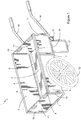
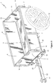
- barrow 1 which in the preferred embodiment is a convertible barrow-trailer configurable as either a barrow or a trailer.
- the Applicant's barrow 1 includes a tray 2, which in the embodiment shown includes a generally flat base 3 and a pair of opposed side walls 4.
- the base and side walls may be connected by a curved corner fitting 5.
- the base and side walls may be formed from plywood or similar material, while the curved corner fitting may be formed from metal, such as aluminium.
- the base 3 and side walls 4 may be supported by a frame, which may include a number of generally U-shaped members 7 spaced along the length of the tray 2 and a pair of longitudinal frame members 8.
- the tray 2 may also include a pair of channels 10 at each end, such that removable panels 11 can be inserted to close each end of the tray.
- the tray may be closed by a suitable cover or lid.
- the tray may be open or enclosed. In some embodiments the tray may be flat. It is not the intention to limit the scope of invention to any particular type of tray.
- a pair of wheels 12 are mounted to the tray 2 by an axle (not shown) mounted within an axle beam 13.
- the barrow 1 also includes a folding leg arrangement 15 (see e.g. Figure 2 ) and a number of handles 16.
- the leg assembly includes two folding legs 17 and two handles 16.
- each leg unit may include a leg 17 mounted to a shaft 18.
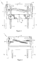
- Each shaft is supported at its front end by a front beam 19, which runs across the width of the tray 2, and at its rear end by a rear shaft support 20. This arrangement allows each shaft to rotate together with its respective leg, allowing the legs to be moved between the unfolded or extended position of Figures 1 to 7 and the folded or stowed position of Figures 8 to 14 . This movement will be discussed in greater detail below.
- each handle 16 is removable. To this end, an end of each handle is formed with a first handle coupling, and a second handle coupling is formed on the body of the barrow or, preferably, as part of the leg unit.
- the first and second handle couplings cooperate to removably mount the handle to the barrow. This mechanism will also be discussed in detail below.
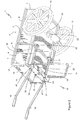
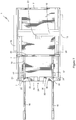
- Figures 8 to 14 show the Applicant's barrow in a second configuration where the handles 16 have been removed, the legs 17 moved to a folded or stowed position and a drawbar 22 attached to the body of the barrow.
- the drawbar may be attached by any suitable mechanism, preferably at two or more drawbar attachment points.
- a first drawbar attachment point 23 is mounted on the axle beam 13 and receives one end of the drawbar.
- a second drawbar attachment point 24 is formed on the front beam 19 and a draw-bolt 25 mounted on the drawbar 22 cooperates with this second point to attach the drawbar 22 to the front beam 19.
- the drawbar 22 may sit within a recess 26 in the front beam 19.
- the second end of the drawbar 22 may include any suitable coupling 27 for attachment to a towing vehicle.
- Figures 2 , 7 and 11 show a stop plate 30, which may be mounted (e.g. riveted) on the front plate or beam 19.
- the stop plate 30 may provide stop surfaces 31, 32, 33, 36 limiting the motion of each leg 17 as discussed below.
- the legs In the folded position, the legs may be retained by a suitable retaining mechanism (not shown), or they may be retained in the folded position by the drawbar 22. As shown in Figure 11 , for example, the legs 17 sit on top of the drawbar 22.
- the shaft 18 is preferably biased to move along its length towards the front end of the barrow 1. This may be achieved by mounting a suitable compression spring 34 in the rear shaft support 20, as shown in Figure 14 .
- a stop 35 may be formed in the wall of the shaft 18, in order to make an internal surface for an end of the spring 34 to bear against. When the drawbar is removed, this bias will tend to cause the legs to sit on top of a lip provided by the stop plate 30.
- Axial motion of the legs towards the front of the barrow will be resisted by a stop surface 36 until the legs are completely unfolded.
- an outer stop surface 31 acts against each leg 17 to prevent further rotational movement.
- a recess in the stop plate 30 allows motion of the shaft 18 along its length (i.e. motion along the shaft's axis of rotation).
- the spring 34 therefore causes the leg 17 and shaft 18 to moved forward until the leg 17 abuts an axial stop surface 33, which acts to prevent further forwards movement of the leg 17 and shaft 18.
- an inner stop surface 32 acts against each leg 17 to prevent that leg from rotating back towards the folded or stowed position.
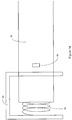
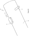
- Figure 15 shows a first handle coupling 40 formed in one end of each handle 16.
- Figure 16 shows a second handle coupling 41 formed in the front end of the shaft 18.
- Figure 17 shows the first and second handle couplings 40, 41 coupled to removably attach a handle 16 to the body of the barrow.
- the first handle coupling 40 may include a pair of projecting pins 42. These pins may be formed by a single rod passing through two apertures in a tubular handle 16.
- the first handle coupling may include a biased button 43, which can be depressed to a position flush with the surface of the handle 16 and is biased to the protruding position shown.
- the second handle coupling 41 may include a pair of opposed "dog leg” slots 45, of which only one is wholly visible in Figure 16 .
- Each dog leg slot 45 includes a first portion 46 extending parallel to the shaft's axis or length, and a second portion 47 extending around the circumference of the shaft 18.
- the second handle coupling may also include a recess 48 formed in the end of the shaft 18.
- a user may attach a handle to the barrow as follows.
- the user aligns the pins 42 with the first portions 46 of the dog leg slots 45 and depresses the button 43.
- the handle 16 may then be moved parallel to the length of the shaft 18 until the pins 42 abut an end surface 50 of the slot 45.
- the depressed button 43 will now be positioned partially inside the tubular shaft 18, but offset from the recess 48.
- the user will depress the button 43 such that it disengages from the recess 48.
- the button may be larger (e.g. longer) than the recess, making it easier to press.
- the button 43 may be elongate such that a first portion 51 is positioned outside the recess and a second portion 52 is within the recess. If the button 43 were entirely within the recess the surface of the shaft 18 would make it more difficult for a user to depress.
- the user may rotate the handle to move the pins 42 along the second portion 47 of slot 45, then withdraw the handle from the shaft, with the pins moving along the first portion 46 of the slot 45.
- first and second handle couplings therefore provide a twist lock connection of the handle to the body of the barrow, and in particular to the shaft 18.
- any suitable coupling providing for removable attachment of the handles may be used, including other forms of twist-lock coupling, threaded couplings, push fits, or any other suitable coupling.
- the front end of the shaft 18 carrying the second handle coupling 41 extends through the front beam 19.
- the end surfaces 50 of the slots 45 are substantially aligned with the front surface of the front beam 19, when the legs 17 are in the unfolded position and abutted against the axial stop surface 33.
- the pins 42 will therefore act against the front surface of the front beam 19 to prevent backwards movement of the shafts 18. In this position rotation of the legs 17 and shafts 18 is also prevented by the inner and outer stop surfaces 32, 31. Attachment of the handles therefore locks the legs in the unfolded position.
- the Applicant's barrow therefore provides a single mechanism that attaches the handles and locks the legs in place. This allows easy conversion between the barrow and trailer configurations.
- the Applicant's barrow also provides excellent performance in both barrow and trailer configurations. Further, the folding nature of the leg assembly allows for compact packaging for shipping, with the legs folded up, handles and wheels removed.
Landscapes
- Engineering & Computer Science (AREA)
- Chemical & Material Sciences (AREA)
- Combustion & Propulsion (AREA)
- Transportation (AREA)
- Mechanical Engineering (AREA)
- Handcart (AREA)
Claims (15)
- Brouette (1) comprenant :i. une cuve (2) ;ii. une ou plusieurs roues (12) ;iii. une ou plusieurs poignées amovibles (16), comprenant chacune un premier raccord de poignée (40) ;iv. une ou plusieurs unités pieds (15), comprenant chacune un pied (17) ayant une position repliée dans laquelle le pied est replié contre la cuve et une position dépliée dans laquelle le pied s'étend vers le bas depuis la cuve ; etv. un ou plusieurs seconds raccords de poignée (41), chacun étant conçu pour s'accoupler à l'un des premiers raccords de poignée afin de fixer l'au moins une poignée amovible à la brouette ;caractérisée en ce que la fixation de l'au moins une poignée amovible à la brouette verrouille l'au moins un pied dans la position dépliée.
- Brouette selon la revendication 1, chaque unité pied comprenant un arbre (18) sur lequel le pied est monté, l'arbre ayant un axe autour duquel le pied tourne entre les positions reliée et dépliée.
- Brouette selon la revendication 2, l'arbre étant un arbre rotatif.
- Brouette selon la revendication 2 ou 3, une extrémité avant de l'arbre fournissant un second raccord de poignée parmi l'un ou plusieurs seconds raccords de poignée, la brouette comprenant une barre ou plaque avant (19),
l'extrémité avant de l'arbre s'étendant à travers la barre ou plaque avant de sorte que le second raccord de poignée soit accessible depuis une extrémité avant de la brouette. - Brouette selon la revendication 4, l'arbre étant conçu pour se déplacer sur sa propre longueur entre une position étendue dans laquelle l'extrémité avant de l'arbre s'étend à travers la barre ou plaque avant de sorte que l'une des poignées amovibles puisse être fixée au second raccord de poignée, et une position rétractée.
- Brouette selon la revendication 5, comprenant une première surface de butée (36) qui empêche le mouvement de l'arbre dans la position étendue à moins que le pied ne se trouve dans la position dépliée.
- Brouette selon la revendication 5 ou 6, l'une des poignées amovibles, lorsqu'elle est accouplée à l'arbre par les premier et second raccords de poignée, empêchant le mouvement de l'arbre hors de la position étendue.
- Brouette selon l'une quelconque des revendications 5 à 7, comprenant une seconde surface de butée qui empêche le mouvement du pied hors de la position dépliée lorsque l'arbre est dans la position étendue.
- Brouette selon l'une quelconque des revendications précédentes comprenant une troisième surface de butée conçue pour limiter vers le bas le mouvement de pliage du pied lorsque le pied atteint une position dépliée.
- Brouette selon l'une quelconque des revendications précédentes, chaque pied étant formé comme un pied sensiblement en forme de U.
- Brouette selon l'une quelconque des revendications précédentes, les premier et second raccords de poignée formant un dispositif de verrouillage par torsion.
- Brouette selon la revendication 11, l'un des premier et second raccords de poignée comprenant une paire de fentes coudées opposées, et l'autre des premier et second raccords de poignée comprenant une paire de broches opposées disposées et dimensionnées pour coopérer avec les fentes coudées.
- Brouette selon la revendication 11 ou 12, l'un des premier et second raccords de poignée comprenant un retrait, et l'autre des premier et second raccords de poignée comprenant un bouton rappelé conçu et dimensionné pour coopérer avec le retrait pour verrouiller ensemble les premier et second raccords de poignée.
- Brouette selon l'une quelconque des revendications précédentes ayant deux poignées amovibles, deux unités pieds, et deux seconds raccords de poignée.
- Brouette selon l'une quelconque des revendications précédentes comprenant en outre un timon amovible, la brouette pouvant être configurée comme une remorque avec le timon fixé et l'au moins un pied dans la position repliée.
Applications Claiming Priority (2)
| Application Number | Priority Date | Filing Date | Title |
|---|---|---|---|
| NZ62149914 | 2014-02-20 | ||
| PCT/NZ2015/050015 WO2015126263A2 (fr) | 2014-02-20 | 2015-02-19 | Brouette |
Publications (2)
| Publication Number | Publication Date |
|---|---|
| EP3107792A2 EP3107792A2 (fr) | 2016-12-28 |
| EP3107792B1 true EP3107792B1 (fr) | 2018-04-11 |
Family
ID=53879204
Family Applications (1)
| Application Number | Title | Priority Date | Filing Date |
|---|---|---|---|
| EP15752319.2A Active EP3107792B1 (fr) | 2014-02-20 | 2015-02-19 | Brouette |
Country Status (4)
| Country | Link |
|---|---|
| US (1) | US9682718B2 (fr) |
| EP (1) | EP3107792B1 (fr) |
| AU (1) | AU2015219583B2 (fr) |
| WO (1) | WO2015126263A2 (fr) |
Families Citing this family (2)
| Publication number | Priority date | Publication date | Assignee | Title |
|---|---|---|---|---|
| USD901121S1 (en) * | 2019-05-07 | 2020-11-03 | Intradin (Huzhou) Precision Technology Co., Ltd. | Electric cart |
| US11738789B2 (en) * | 2021-09-30 | 2023-08-29 | William Kurt Feick | Wheelbarrow and kit for assembling same |
Family Cites Families (11)
| Publication number | Priority date | Publication date | Assignee | Title |
|---|---|---|---|---|
| US4261596A (en) | 1979-05-02 | 1981-04-14 | W. C. Bradley Co. | Folding utility cart |
| SU984914A1 (ru) | 1981-03-09 | 1982-12-30 | Специальное Конструкторское Бюро По Ирригационным Машинам Объединения "Внииземмаш" | Складна одноколесна тележка |
| US4740008A (en) | 1987-02-12 | 1988-04-26 | Johnson James A | Convertible wheelbarrow/cart |
| US4789171A (en) | 1987-07-13 | 1988-12-06 | Porter Lynn L | Multipurpose barrow vehicle |
| FR2749254B1 (fr) | 1996-05-28 | 1998-08-14 | Bonnet Alain | Vehicule a bras "type brouette" transformable et attelable, multifonctions |
| CA2262029A1 (fr) | 1999-01-25 | 2000-07-25 | Normand L. Roy | La brouette |
| US7226072B2 (en) * | 2000-06-28 | 2007-06-05 | Shapiro Richard N | Compact wheelbarrow and cart assembly, shipping and display methods including hitch and trailing conversions |
| WO2006022728A2 (fr) * | 2004-08-20 | 2006-03-02 | Shapiro Richard N | Brouettes et chariots compacts comprenant des roues, des supports et des manches escamotables |
| DE202005000487U1 (de) * | 2005-01-11 | 2005-03-17 | Von Melle Daniela A | Wandelbare Anhänger-Kippkarre |
| GB2445051B (en) | 2007-10-04 | 2009-05-06 | Bryan Smither | Wheelbarrow |
| US20140169921A1 (en) | 2012-12-19 | 2014-06-19 | Mark Carey | Cargo carrier |
-
2015
- 2015-02-19 US US15/120,128 patent/US9682718B2/en active Active
- 2015-02-19 EP EP15752319.2A patent/EP3107792B1/fr active Active
- 2015-02-19 WO PCT/NZ2015/050015 patent/WO2015126263A2/fr not_active Ceased
- 2015-02-19 AU AU2015219583A patent/AU2015219583B2/en active Active
Also Published As
| Publication number | Publication date |
|---|---|
| WO2015126263A3 (fr) | 2016-03-10 |
| EP3107792A2 (fr) | 2016-12-28 |
| US9682718B2 (en) | 2017-06-20 |
| AU2015219583B2 (en) | 2018-11-08 |
| US20170072977A1 (en) | 2017-03-16 |
| NZ724364A (en) | 2021-02-26 |
| WO2015126263A2 (fr) | 2015-08-27 |
| AU2015219583A1 (en) | 2016-10-06 |
Similar Documents
| Publication | Publication Date | Title |
|---|---|---|
| US10232867B1 (en) | Multi-functional vehicle caddy and associated use thereof | |
| US4878680A (en) | Stroller car seat | |
| US6752405B1 (en) | Convertible twin/single seat stroller | |
| WO2007109317A3 (fr) | Vehicule pliant | |
| US11273856B2 (en) | Foldable carriage | |
| US2555178A (en) | Folding maid service truck | |
| AU2013100266A4 (en) | A convertible tandem stroller frame | |
| EP1522489A3 (fr) | Véhicule repliable | |
| JPH08230676A (ja) | 折りたたみ式カート | |
| CA2247147A1 (fr) | Ameliorations relatives a une valise roulante pliable | |
| US20120074664A1 (en) | Market Basket System | |
| US5028060A (en) | Utility cart | |
| EP3107792B1 (fr) | Brouette | |
| US9573639B1 (en) | Wheel retraction assembly, cart and related components | |
| EP3194245B1 (fr) | Chariot pliant | |
| KR101436284B1 (ko) | 자전거용 다용도 트레일러 | |
| US20090159627A1 (en) | Portable hitch mounted cargo carrier | |
| CN103407470B (zh) | 用于组合式折叠拖车的后车架组件 | |
| US9394017B2 (en) | Cart with folding support | |
| NZ724364B2 (en) | A barrow | |
| US7390011B1 (en) | Space saver | |
| FR2658146A1 (fr) | Dispositif de chariot mobile pliable multi-fonctions. | |
| US20180362059A1 (en) | Utility Handcart | |
| US8936269B1 (en) | Retractable frame structure for tandem trailer | |
| GB2401586A (en) | Foldable trailer |
Legal Events
| Date | Code | Title | Description |
|---|---|---|---|
| PUAI | Public reference made under article 153(3) epc to a published international application that has entered the european phase |
Free format text: ORIGINAL CODE: 0009012 |
|
| STAA | Information on the status of an ep patent application or granted ep patent |
Free format text: STATUS: REQUEST FOR EXAMINATION WAS MADE |
|
| 17P | Request for examination filed |
Effective date: 20160909 |
|
| AK | Designated contracting states |
Kind code of ref document: A2 Designated state(s): AL AT BE BG CH CY CZ DE DK EE ES FI FR GB GR HR HU IE IS IT LI LT LU LV MC MK MT NL NO PL PT RO RS SE SI SK SM TR |
|
| AX | Request for extension of the european patent |
Extension state: BA ME |
|
| DAX | Request for extension of the european patent (deleted) | ||
| RIC1 | Information provided on ipc code assigned before grant |
Ipc: B62B 5/06 20060101ALI20170911BHEP Ipc: B62B 1/00 20060101AFI20170911BHEP Ipc: B62B 1/20 20060101ALI20170911BHEP Ipc: B62B 5/00 20060101ALI20170911BHEP |
|
| GRAP | Despatch of communication of intention to grant a patent |
Free format text: ORIGINAL CODE: EPIDOSNIGR1 |
|
| STAA | Information on the status of an ep patent application or granted ep patent |
Free format text: STATUS: GRANT OF PATENT IS INTENDED |
|
| INTG | Intention to grant announced |
Effective date: 20171031 |
|
| GRAS | Grant fee paid |
Free format text: ORIGINAL CODE: EPIDOSNIGR3 |
|
| GRAA | (expected) grant |
Free format text: ORIGINAL CODE: 0009210 |
|
| STAA | Information on the status of an ep patent application or granted ep patent |
Free format text: STATUS: THE PATENT HAS BEEN GRANTED |
|
| AK | Designated contracting states |
Kind code of ref document: B1 Designated state(s): AL AT BE BG CH CY CZ DE DK EE ES FI FR GB GR HR HU IE IS IT LI LT LU LV MC MK MT NL NO PL PT RO RS SE SI SK SM TR |
|
| REG | Reference to a national code |
Ref country code: GB Ref legal event code: FG4D |
|
| REG | Reference to a national code |
Ref country code: CH Ref legal event code: EP |
|
| REG | Reference to a national code |
Ref country code: AT Ref legal event code: REF Ref document number: 987696 Country of ref document: AT Kind code of ref document: T Effective date: 20180415 |
|
| REG | Reference to a national code |
Ref country code: IE Ref legal event code: FG4D |
|
| REG | Reference to a national code |
Ref country code: DE Ref legal event code: R096 Ref document number: 602015009953 Country of ref document: DE |
|
| REG | Reference to a national code |
Ref country code: NL Ref legal event code: MP Effective date: 20180411 |
|
| REG | Reference to a national code |
Ref country code: LT Ref legal event code: MG4D |
|
| PG25 | Lapsed in a contracting state [announced via postgrant information from national office to epo] |
Ref country code: NL Free format text: LAPSE BECAUSE OF FAILURE TO SUBMIT A TRANSLATION OF THE DESCRIPTION OR TO PAY THE FEE WITHIN THE PRESCRIBED TIME-LIMIT Effective date: 20180411 |
|
| PG25 | Lapsed in a contracting state [announced via postgrant information from national office to epo] |
Ref country code: BG Free format text: LAPSE BECAUSE OF FAILURE TO SUBMIT A TRANSLATION OF THE DESCRIPTION OR TO PAY THE FEE WITHIN THE PRESCRIBED TIME-LIMIT Effective date: 20180711 Ref country code: NO Free format text: LAPSE BECAUSE OF FAILURE TO SUBMIT A TRANSLATION OF THE DESCRIPTION OR TO PAY THE FEE WITHIN THE PRESCRIBED TIME-LIMIT Effective date: 20180711 Ref country code: PT Free format text: LAPSE BECAUSE OF FAILURE TO SUBMIT A TRANSLATION OF THE DESCRIPTION OR TO PAY THE FEE WITHIN THE PRESCRIBED TIME-LIMIT Effective date: 20180813 Ref country code: LT Free format text: LAPSE BECAUSE OF FAILURE TO SUBMIT A TRANSLATION OF THE DESCRIPTION OR TO PAY THE FEE WITHIN THE PRESCRIBED TIME-LIMIT Effective date: 20180411 Ref country code: FI Free format text: LAPSE BECAUSE OF FAILURE TO SUBMIT A TRANSLATION OF THE DESCRIPTION OR TO PAY THE FEE WITHIN THE PRESCRIBED TIME-LIMIT Effective date: 20180411 Ref country code: ES Free format text: LAPSE BECAUSE OF FAILURE TO SUBMIT A TRANSLATION OF THE DESCRIPTION OR TO PAY THE FEE WITHIN THE PRESCRIBED TIME-LIMIT Effective date: 20180411 Ref country code: AL Free format text: LAPSE BECAUSE OF FAILURE TO SUBMIT A TRANSLATION OF THE DESCRIPTION OR TO PAY THE FEE WITHIN THE PRESCRIBED TIME-LIMIT Effective date: 20180411 Ref country code: SE Free format text: LAPSE BECAUSE OF FAILURE TO SUBMIT A TRANSLATION OF THE DESCRIPTION OR TO PAY THE FEE WITHIN THE PRESCRIBED TIME-LIMIT Effective date: 20180411 Ref country code: PL Free format text: LAPSE BECAUSE OF FAILURE TO SUBMIT A TRANSLATION OF THE DESCRIPTION OR TO PAY THE FEE WITHIN THE PRESCRIBED TIME-LIMIT Effective date: 20180411 |
|
| PG25 | Lapsed in a contracting state [announced via postgrant information from national office to epo] |
Ref country code: HR Free format text: LAPSE BECAUSE OF FAILURE TO SUBMIT A TRANSLATION OF THE DESCRIPTION OR TO PAY THE FEE WITHIN THE PRESCRIBED TIME-LIMIT Effective date: 20180411 Ref country code: LV Free format text: LAPSE BECAUSE OF FAILURE TO SUBMIT A TRANSLATION OF THE DESCRIPTION OR TO PAY THE FEE WITHIN THE PRESCRIBED TIME-LIMIT Effective date: 20180411 Ref country code: GR Free format text: LAPSE BECAUSE OF FAILURE TO SUBMIT A TRANSLATION OF THE DESCRIPTION OR TO PAY THE FEE WITHIN THE PRESCRIBED TIME-LIMIT Effective date: 20180712 Ref country code: RS Free format text: LAPSE BECAUSE OF FAILURE TO SUBMIT A TRANSLATION OF THE DESCRIPTION OR TO PAY THE FEE WITHIN THE PRESCRIBED TIME-LIMIT Effective date: 20180411 |
|
| REG | Reference to a national code |
Ref country code: AT Ref legal event code: MK05 Ref document number: 987696 Country of ref document: AT Kind code of ref document: T Effective date: 20180411 |
|
| REG | Reference to a national code |
Ref country code: DE Ref legal event code: R097 Ref document number: 602015009953 Country of ref document: DE |
|
| PG25 | Lapsed in a contracting state [announced via postgrant information from national office to epo] |
Ref country code: DK Free format text: LAPSE BECAUSE OF FAILURE TO SUBMIT A TRANSLATION OF THE DESCRIPTION OR TO PAY THE FEE WITHIN THE PRESCRIBED TIME-LIMIT Effective date: 20180411 Ref country code: AT Free format text: LAPSE BECAUSE OF FAILURE TO SUBMIT A TRANSLATION OF THE DESCRIPTION OR TO PAY THE FEE WITHIN THE PRESCRIBED TIME-LIMIT Effective date: 20180411 Ref country code: EE Free format text: LAPSE BECAUSE OF FAILURE TO SUBMIT A TRANSLATION OF THE DESCRIPTION OR TO PAY THE FEE WITHIN THE PRESCRIBED TIME-LIMIT Effective date: 20180411 Ref country code: CZ Free format text: LAPSE BECAUSE OF FAILURE TO SUBMIT A TRANSLATION OF THE DESCRIPTION OR TO PAY THE FEE WITHIN THE PRESCRIBED TIME-LIMIT Effective date: 20180411 Ref country code: RO Free format text: LAPSE BECAUSE OF FAILURE TO SUBMIT A TRANSLATION OF THE DESCRIPTION OR TO PAY THE FEE WITHIN THE PRESCRIBED TIME-LIMIT Effective date: 20180411 Ref country code: SK Free format text: LAPSE BECAUSE OF FAILURE TO SUBMIT A TRANSLATION OF THE DESCRIPTION OR TO PAY THE FEE WITHIN THE PRESCRIBED TIME-LIMIT Effective date: 20180411 |
|
| PLBE | No opposition filed within time limit |
Free format text: ORIGINAL CODE: 0009261 |
|
| STAA | Information on the status of an ep patent application or granted ep patent |
Free format text: STATUS: NO OPPOSITION FILED WITHIN TIME LIMIT |
|
| PG25 | Lapsed in a contracting state [announced via postgrant information from national office to epo] |
Ref country code: SM Free format text: LAPSE BECAUSE OF FAILURE TO SUBMIT A TRANSLATION OF THE DESCRIPTION OR TO PAY THE FEE WITHIN THE PRESCRIBED TIME-LIMIT Effective date: 20180411 Ref country code: IT Free format text: LAPSE BECAUSE OF FAILURE TO SUBMIT A TRANSLATION OF THE DESCRIPTION OR TO PAY THE FEE WITHIN THE PRESCRIBED TIME-LIMIT Effective date: 20180411 |
|
| 26N | No opposition filed |
Effective date: 20190114 |
|
| PG25 | Lapsed in a contracting state [announced via postgrant information from national office to epo] |
Ref country code: SI Free format text: LAPSE BECAUSE OF FAILURE TO SUBMIT A TRANSLATION OF THE DESCRIPTION OR TO PAY THE FEE WITHIN THE PRESCRIBED TIME-LIMIT Effective date: 20180411 |
|
| REG | Reference to a national code |
Ref country code: CH Ref legal event code: PL |
|
| PG25 | Lapsed in a contracting state [announced via postgrant information from national office to epo] |
Ref country code: LU Free format text: LAPSE BECAUSE OF NON-PAYMENT OF DUE FEES Effective date: 20190219 Ref country code: MC Free format text: LAPSE BECAUSE OF FAILURE TO SUBMIT A TRANSLATION OF THE DESCRIPTION OR TO PAY THE FEE WITHIN THE PRESCRIBED TIME-LIMIT Effective date: 20180411 |
|
| REG | Reference to a national code |
Ref country code: BE Ref legal event code: MM Effective date: 20190228 |
|
| REG | Reference to a national code |
Ref country code: IE Ref legal event code: MM4A |
|
| PG25 | Lapsed in a contracting state [announced via postgrant information from national office to epo] |
Ref country code: CH Free format text: LAPSE BECAUSE OF NON-PAYMENT OF DUE FEES Effective date: 20190228 Ref country code: LI Free format text: LAPSE BECAUSE OF NON-PAYMENT OF DUE FEES Effective date: 20190228 |
|
| PG25 | Lapsed in a contracting state [announced via postgrant information from national office to epo] |
Ref country code: IE Free format text: LAPSE BECAUSE OF NON-PAYMENT OF DUE FEES Effective date: 20190219 |
|
| PG25 | Lapsed in a contracting state [announced via postgrant information from national office to epo] |
Ref country code: BE Free format text: LAPSE BECAUSE OF NON-PAYMENT OF DUE FEES Effective date: 20190228 |
|
| PG25 | Lapsed in a contracting state [announced via postgrant information from national office to epo] |
Ref country code: TR Free format text: LAPSE BECAUSE OF FAILURE TO SUBMIT A TRANSLATION OF THE DESCRIPTION OR TO PAY THE FEE WITHIN THE PRESCRIBED TIME-LIMIT Effective date: 20180411 |
|
| PG25 | Lapsed in a contracting state [announced via postgrant information from national office to epo] |
Ref country code: MT Free format text: LAPSE BECAUSE OF NON-PAYMENT OF DUE FEES Effective date: 20190219 |
|
| PG25 | Lapsed in a contracting state [announced via postgrant information from national office to epo] |
Ref country code: CY Free format text: LAPSE BECAUSE OF FAILURE TO SUBMIT A TRANSLATION OF THE DESCRIPTION OR TO PAY THE FEE WITHIN THE PRESCRIBED TIME-LIMIT Effective date: 20180411 |
|
| PG25 | Lapsed in a contracting state [announced via postgrant information from national office to epo] |
Ref country code: IS Free format text: LAPSE BECAUSE OF FAILURE TO SUBMIT A TRANSLATION OF THE DESCRIPTION OR TO PAY THE FEE WITHIN THE PRESCRIBED TIME-LIMIT Effective date: 20180811 |
|
| PG25 | Lapsed in a contracting state [announced via postgrant information from national office to epo] |
Ref country code: HU Free format text: LAPSE BECAUSE OF FAILURE TO SUBMIT A TRANSLATION OF THE DESCRIPTION OR TO PAY THE FEE WITHIN THE PRESCRIBED TIME-LIMIT; INVALID AB INITIO Effective date: 20150219 |
|
| PG25 | Lapsed in a contracting state [announced via postgrant information from national office to epo] |
Ref country code: MK Free format text: LAPSE BECAUSE OF FAILURE TO SUBMIT A TRANSLATION OF THE DESCRIPTION OR TO PAY THE FEE WITHIN THE PRESCRIBED TIME-LIMIT Effective date: 20180411 |
|
| PGFP | Annual fee paid to national office [announced via postgrant information from national office to epo] |
Ref country code: GB Payment date: 20260206 Year of fee payment: 12 |
|
| PGFP | Annual fee paid to national office [announced via postgrant information from national office to epo] |
Ref country code: DE Payment date: 20260218 Year of fee payment: 12 |
|
| PGFP | Annual fee paid to national office [announced via postgrant information from national office to epo] |
Ref country code: FR Payment date: 20260218 Year of fee payment: 12 |