EP3108307B1 - Schlagwerkvorrichtung für eine uhr - Google Patents
Schlagwerkvorrichtung für eine uhr Download PDFInfo
- Publication number
- EP3108307B1 EP3108307B1 EP15704544.4A EP15704544A EP3108307B1 EP 3108307 B1 EP3108307 B1 EP 3108307B1 EP 15704544 A EP15704544 A EP 15704544A EP 3108307 B1 EP3108307 B1 EP 3108307B1
- Authority
- EP
- European Patent Office
- Prior art keywords
- striking
- lever
- barrel
- wheel
- striking mechanism
- Prior art date
- Legal status (The legal status is an assumption and is not a legal conclusion. Google has not performed a legal analysis and makes no representation as to the accuracy of the status listed.)
- Active
Links
Images












Classifications
-
- G—PHYSICS
- G04—HOROLOGY
- G04B—MECHANICALLY-DRIVEN CLOCKS OR WATCHES; MECHANICAL PARTS OF CLOCKS OR WATCHES IN GENERAL; TIME PIECES USING THE POSITION OF THE SUN, MOON OR STARS
- G04B21/00—Indicating the time by acoustic means
- G04B21/02—Regular striking mechanisms giving the full hour, half hour or quarter hour
- G04B21/12—Reiterating watches or clocks
-
- G—PHYSICS
- G04—HOROLOGY
- G04B—MECHANICALLY-DRIVEN CLOCKS OR WATCHES; MECHANICAL PARTS OF CLOCKS OR WATCHES IN GENERAL; TIME PIECES USING THE POSITION OF THE SUN, MOON OR STARS
- G04B21/00—Indicating the time by acoustic means
- G04B21/02—Regular striking mechanisms giving the full hour, half hour or quarter hour
- G04B21/14—Winding-up the striking mechanism by the clockwork; winding up the clockwork by the striking mechanism
Definitions
- the present invention relates to a striking mechanism for a timepiece such as a wristwatch or a pocket watch.
- the striking mechanism is for example a minute repeater or a big ring.
- the present invention more particularly relates to a striking mechanism comprising at least one stamp, an actuating device for actuating the stamp (s), a striking barrel, a rocking clutch device for coupling the device of actuation with a striking barrel, the flip-flop of the clutch device being arranged to pivot between a first position where the actuating device is coupled to the striking barrel and a second position where the actuating device is decoupled from the striking barrel, and a locking device for blocking the ringer barrel.
- the actuating device comprises three rakes or ratchets of the hours, quarters and minutes which actuate lifts which themselves actuate hammers which strike the stamps.
- the hour rake has a toothed sector which cooperates with a striking gear connecting the striking barrel to a regulator, via the clutch device.
- the locking device is used to stop the mechanism at the end of the ring.
- This locking device comprises a cam defined by the minute rake, a locking rocker cooperating with the cam and traversing the movement, a locking lever cooperating with the locking lever on the other side of the movement, and a brake defined by the locking lever and which is applied against a steering wheel forming the regulator.
- the brake is removed from the steering wheel, to release the drive train comprising the ringer barrel, the ring gear and the regulator, at the beginning of the fall of the rake minutes caused by the clutch, then is reapplied against the steering wheel to stop the mechanism at the end of the ring.
- This locking device is complicated because of the large number of parts that compose it and the fact that it requires to cross the movement by a blocking lever.
- the ringer barrel is free when the clutch device is in its disengaged state. As a result, while the rakes are taking information, the ringer drum unwinds unnecessarily, which is a loss of energy.
- the patent application EP 1925997 mentions in its introductory part conventional ringing mechanisms in which a pin disposed on the minute rake actuates the locking and unlocking of the energy source (the ringer barrel). According to this document, it is important that the energy source is released only after the rakes have fallen on their cam, but coordinating the different steps of unwinding the ring to achieve this result is difficult.
- the document EP 1925997 discloses a striking mechanism whose clutch device comprises a differential gear disposed in the ring gear and a latch or latch that can act on the differential gear to lock or unlock a carrier of the latter. A stop element carried by a double rocker can block or unblock the regulator and therefore the barrel of ringing.
- the rocker which acts on the differential gear as well as the double rocker are actuated in a coordinated manner by a camshaft which thus controls the engaged / disengaged state of the clutch device.
- This mechanism has the disadvantage of having a large number of parts.
- the relative angular position of cams of the camshaft must be very accurate to properly manage the timing of the ring.
- the ringer barrel can be dedicated to the ringing or be common to the movement with which the striking mechanism is associated.
- the ringer barrel provides the energy required for the actuator to activate the tone (s) and sound the number of strokes required when the flip-flop is in the first position.
- the actuating device can take the information of the number of blow (s) to ring under the action of one or more return springs.
- the locking member preferably forms a single piece with the rocker but it can also be an insert attached to the rocker.
- the locking member is a spout.
- the locking member is arranged to cooperate with a toothed member, such as a star or a wheel, kinematically connected to the ringer barrel.
- the clutch device comprises a pinion or clutch wheel mounted on the rocker, this pinion or clutch wheel coupling the actuating device to the ringer barrel when the rocker is in the first position and not coupling the actuating device to the ringer barrel when the latch is in the second position.
- the clutch device comprises a differential gear disposed between the striking barrel and the actuating device and on which can act a second locking member carried by the rocker.
- the clutch device comprises a vertical clutching mobile disposed between the striking cylinder and the actuating device and comprising an element, typically a wheel, which is movable along an axis of the clutch.
- mobile vertical clutch to pass the clutch device from a state engaged to a disengaged state and vice versa, the displacement of said element being able to be controlled by the rocker.
- the rocker can carry an abutment member arranged to, in the event of an impact, prevent a displacement of said element along said axis against the action of a return spring to which said element is subjected, when the rocker is in its first position.
- the locking device may comprise an additional locking member in the form of an abutment against which comes to bear a rake of the hours of the actuating device under the action of the ringer barrel at the end of the ring.
- additional locking member makes it possible to immobilize all the striking mechanism at rest.
- the ringer barrel is connected to a regulator via a ring gear.
- the rocker carries a projecting element which, when the striking mechanism is in the rest state, is held in abutment against a trigger lever by a return spring of the rocker, this trigger lever being able to be pivoted by a manual actuator to release the projecting element and with it the rocker and pass the rocker from its first position to its second position under the action of its return spring and thus trigger the ringing.
- the striking mechanism may further include a first lock lever arranged to abut the protruding member and prevent the release of the protruding member when the energy accumulated in the ringer barrel is less than a predetermined value.
- the first blocking lever can be arranged to be controlled by a ringing power reserve display wheel.
- the striking mechanism may further comprise a second locking lever arranged to serve as a stop for the projecting element and to prevent the releasing the protruding element when a winding stem of the timepiece is in a setting position.
- the present invention also proposes a timepiece comprising a striking mechanism as defined above and a movement, characterized in that the movement comprises its own barrel, and in that a device is provided for winding up the winding barrel by a rotation of a winding stem in one direction and wind up the barrel of movement by a rotation of the winding stem in the other direction, said device comprising an input wheel arranged to be driven into one way or the other by the winding stem, at least one first pawl carried by one of the two faces of the input wheel, at least one second pawl carried by the other of the two faces of the input wheel , a first pinion coaxial with the input wheel and comprising a unidirectional toothing cooperating with the first pawl, a second pinion coaxial with the input wheel and comprising a unidirectional toothing cooperating with the two x ratchet, a first output wheel secured to the first pinion and kinematically connected to the ratchet barrel ratchet and a second output wheel secured to the second pinion
- ratchet (with the exception of a barrel ratchet) means any toothed member intended to actuate one or more striking hammer lifts.
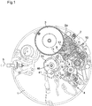
- a striking mechanism intended to be integrated or added to the movement of a timepiece, typically a wristwatch, comprises, in a frame 1, a ring gear 2 connecting a power source 3 to a regulator 4.
- the energy source 3 is typically a striking barrel in engagement with a wheel 2a of the ring gear 2 and can be reassembled by turning a winding rod 5.
- the rod of winder 5 is preferably the winding stem of the movement, serving to raise also the barrel of the movement.
- the regulator 4 is for example a centrifugal regulator (Watt regulator). It serves to regulate the tempo of the shots to ring.
- a clutch rocker 6 pivoting about an axis 7 carries two pinions 8, 9 rotatable relative to the rocker 6.
- the pinion 8 is rotatable about the axis 7 and is permanently engaged with a pinion 10 integral with a ringing shaft 11.
- the pinion 8 also meshes permanently with the pinion 9, called “clutch gear”.
- the clutch gear 9 meshes with a pinion 12 which is engaged with the ringer barrel 3 and thus transmits the movement of the ringer barrel 3 to the ringer shaft 11 via the pinions 8, 10.
- position, or disengaged position, of the clutch rocker 6 (cf.
- the clutch gear 9 does not mesh with the pinion 12 and thus leaves the ringing shaft 11 free to rotate.
- the clutch gear 9 carried by the clutch rocker 6 could, in the engaged position, meshing with a pinion or wheel of the ring gear 2 so as to receive the movement of the barrel ring 3 via said train.
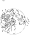
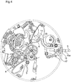
- the clutch rocker 6 is subjected to the action of a return spring 13 which tends to rotate in the direction of disengagement. At one of its ends the clutch rocker 6 carries a pin 14 which, when the striking mechanism is in its rest state ( figure 3 ), is held in abutment against a first end of a striking trip lever 15 by the action of the return spring 13, thus maintaining the clutch rocker 6 in its engaged position. In its rest position the ringing trip lever 15 is held in abutment against a surface 1a of the frame 1 by an on-off spring 17 (cf. figures 3 and 16 ).
- the bell release lever 15 can be actuated to release the pin 14 and thus the clutch rocker 6 ( figure 4 ) by axially pushing a tube 15a which acts on a second end 16 of the striking trip lever 15.
- the tube 15a surrounds the winding stem 5 and is associated with a thrust ring (not shown) mounted at the end of 5.
- the striking trip lever 15 could be actuated by a push button independent of the winding rod 5.
- the clutch rocker 6 defines a spout 18 arranged to cooperate with a stopping star 19 secured to a wheel 2b of the ring gear 2 (cf. figures 1 and 2 ).
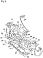
- ratchets 20, 21, 22 are mounted on the ringing shaft 11 (cf. figures 5 and 6 ) on the ringing shaft 11 (cf. figures 5 and 6 ) on the ringing shaft 11 (cf. figures 5 and 6 ) on the ringing shaft 11 (cf. figures 5 and 6 ) on the ringing shaft 11 (cf. figures 5 and 6 ) on the ringing shaft 11 (cf. figures 5 and 6 ) are mounted three ratchets 20, 21, 22 in the form of wheels. These ratchets include a ratchet of hours 20, a ratchet of quarters 21 and a ratchet of minutes 22.
- the ratchet of hours 20 is integral with ringing shaft 11 and pinion 10.
- the ratchets of quarters 21 and minutes 22 are they are free to rotate relative to the ringing shaft 11.
- the teeth of the ratchets 20, 21, 22 serve to actuate ringing levers 23, 24, 25, 26 which themselves actuate hammers 27,
- the levees include a 23 hour lift, a first coaxial shift 24 at the 23 hour lift, a 25 minute lift and a second quarter lift 26 coaxial at the 25 minute lift.
- Each group of levees 23-24 respectively 25-26, is arranged to actuate a respective hammer 27, 28, which is arranged to hit a respective patch 29, 30, the two patches 29, 30 producing different sounds.
- the hour ratchet 20 comprises a toothing with 12 teeth to actuate the lifting of the hours 23 so that it actuates the hammer 27, called "hammer hours”.
- the minute ratchet 22 includes a toothing with 14 teeth to actuate the lifting of the minutes 25 so that it actuates the hammer 28, said "hammer minutes”.
- the quarter ratchet 21 comprises two 3-toothed teeth for actuating the two lifts of the quarters 24, 26, respectively, so that they alternately operate the hour hammer 27 and the minute hammer 28.
- the ratchets of the hours, quarters and minutes 20, 21, 22 are respectively integral with gears hours, quarters and minutes 31, 32, 33 (cf. figure 5 ).
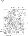
- the pinion hours 31 is engaged with a toothing of a rake hours 34 (cf. figures 6 and 7 ).
- the quarter gear 32 is engaged with a tooth of a quarter rake 35.
- the minute gear 33 is engaged with a toothing of a minute rake 36.
- the quarter and minute rakes 35, 36 pivot about 37.
- the rake of the hours 34 pivots preferably about an axis 38 distinct from the pivot axis 37 of the rakes quarters and minutes 35, 36, but could alternatively rotate around the same pivot axis 37 as the quarter and minute rakes 35, 36.
- a hours feeler 39 is pivotally mounted about the pivot axis 38 of the hour rake 34.
- the spout 40 of the hour sensor 39 is arranged to cooperate with an hour cam 41 (visible on the figure 1 ).
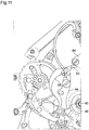
- a pin 42 (cf. figure 9 ) carried by the hours probe 39 and engaged in an aperture 43 of the hours rake 34 defines a relative angular displacement range between the hours probe 39 and the rake hours 34.
- a quarter probe 44 is pivotally mounted around the pivot axis 37 of the quarter rake 35 and minute rake 36.
- the spoiler 45 of the quarter probe 44 is arranged to cooperate with a quarter cam 46 (cf. figure 7 ).
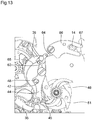
- a pin 47 carried by the quarter rake 35 and engaged in an opening 48 of the quarter sensor 44 (cf. figure 13 ) defines a relative angular displacement range between the quarter feeler 44 and the quarter rake 35.
- a minute feeler 49 is integral with the minute rake 36 and preferably in one piece with the minute rake 36 (cf. figure 6 ).
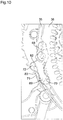
- the nozzle 50 of the minute sensor 49 is arranged to cooperate with a minute cam 51 (cf. figure 12 ).
- the hour, quarter and minute cams 41, 46, 51 are of conventional type and are driven by the movement in a conventional manner.
- the cams of quarters and minutes 46, 51 pivot about the same axis which can be that of the roadway of the movement.
- the hour cam 41 it is preferably non-coaxial with the cams of quarters and minutes 46, 51.
- Each rake hours, quarters and minutes 34, 35, 36 is subjected to the action of a spring recall 52, 53, 54 (cf. figures 6 and 7 ) tending to rotate in the direction that brings the tip of the probe corresponding to the corresponding cam.
- the hour rake 34 carries a quarter trigger latch 55 which pivots about an axis 56 (cf. figures 6 and 7 ).
- the hour sensor 39 and the quarter trip lever 55 are connected by a spring 57 which keeps these two parts 39, 55 in contact with each other.
- the quarter trigger latch 55 is arranged to cooperate with a quarter isolator 58 mounted on the frame 1 of the striking mechanism.
- the quarter isolator 58 is pivotally mounted about an axis 59 and its angular displacement is limited by a pin 60 fixed to the frame 1 and engaged in an opening 61 of the isolator of the quarters 58.
- the isolator of the quarters 58 carries a pin 62 which, in the rest position of the isolator of the quarts 58, serves at a certain moment of stop at the rake of the quarters.
- the isolator of the quarters 58 is subjected to the action of a return spring 58a tending to keep him in his rest position.
- the quarter feeler 44 comprises at its end opposite to that defining the spout of the quarters 45 a spout 63 arranged to actuate a first clutch control lever 64 (cf. figure 13 ).
- the first clutch control lever 64 is mounted on the quarter rake 35 and subjected to the action of a return spring 65 which keeps it in contact with the nose 63 of the quarter feeler 44.
- the first control lever clutch 64 is arranged to actuate a second clutch control lever 66 mounted on the frame 1.
- the second clutch control lever 66 defines a fork 67 which receives the pin 14 carried by the clutch rocker 6.
- the quarter rake 35 and the minute rake 36 are connected to each other by a pawl or hook 68 (cf. figure 8 ) pivotally mounted on the quarter rake 35 and defining a tooth 69 arranged to cooperate with a second set of teeth 70 of the minutes rake 36 to secure the rakes quarters and minutes 35, 36.
- the pawl 68 is subjected to the action of a return spring 68a which tends to hold the tooth 69 in the toothing 70.
- a pawl stop 71, fixed on the frame 1 is arranged to cooperate with another tooth 72 of the pawl 68 (cf. figure 10 ) to rotate the pawl 68 against the action of its return spring and thus clear the tooth 69 of the toothing 70 and separate the rakes quarters and minutes 35, 36.
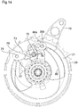
- the hour and quarter ratchets 20, 21 are connected to each other by a lever 73 carried by the quarter ratchet 21 and pivotally mounted relative to the quarter ratchet 21 about an axis 74 (cf. figure 14 ).
- the lever 73 carries a drive pin 75 arranged to cooperate with a stepped surface of the hour ratchet 20.
- the stepped surface extends in the plane of the hour ratchet 20, that is to say in a plane perpendicular to the common axis of rotation of the ratchets 20, 21, and connects the peripheral portion of the hour ratchet 20 to its central portion along a curve.
- the stepped surface defines steps or steps 76 and four risers 77.
- Each step 76 is substantially concentric with the axis of rotation of the ratchets 20, 21 but is located at a radial position different from the other steps.
- the lever 73 extends and pivots in a plane perpendicular to the axis of rotation of the ratchets 20, 21.
- the driving pin 75 extends parallel to said axis of rotation in order to cooperate with the stepped surface 76 77.
- the drive pin 75 is also adapted to cooperate with a lever stop 78 fixed to the frame 1 and comprising a surface 79 of angular positioning of the lever 73 extending in a curve coinciding with that mentioned above when the ratchet hours 20 is in a predetermined angular position (cf. figure 15 ).
- the lever 73 is subjected to the action of a return spring 80 which tends to pivot the lever 73 in the counterclockwise direction of the figure 14 .
- the return spring 80 is preferably in one piece with the lever 73, as shown, and mounted by one of its ends 80a on the ratchet of the quarters 21.
- the end 80a is for example mounted freely in rotation about a pin 80b fixed on the quarter ratchet 21.
- the striking mechanism operates as follows.
- the clutch lever 6 In the rest state of the striking mechanism, the clutch lever 6 is in its engaged position (cf. figure 1 ), its spout 18 is out of the toothing of the stopping star 19 and the ringing barrel 3, the ring gear 2, the ratchets 20, 21, 22 and the rakes 34, 35, 36 are stationary.
- the hour rake 34 is held in abutment against the pin 60 (cf. figure 7 ) by the force of the ringer barrel 3, which prevents the ringer barrel 3 to unwind.
- the quarter ratchet 21 is retained by the hour ratchet 20 via the lever 73 whose drive pin 75 bears against one of the risers 77 (cf. figure 15 ).
- the minute rake 36 is retained by the quarter rake 35 via the pawl 68 whose tooth 69 is engaged in the toothing 70 (cf. figure 8 ).
- the rakes of hours, quarters and minutes 34, 35, 36 fall under the action of their return springs 52, 53, 54, but the quarter rake 35 is stopped in its race by the pin 62 of the insulator of the quarters 58 (cf. figure 7 ).
- the minute rake 36 is linked to the quarter rake 35 by the ratchet 68, it is also stopped in its race.
- the falling hour rake 34 moves the hour sensor 39 towards the hour cam 41.
- the spout 40 of the hour sensor 39 comes into operation. contact with the hour cam 41 to take the information of the number of hours to ring.
- the hour rake 34 continues its course, and as the quarter tripping lever 55 is in abutment against the probe of hour 39, the quarter trigger latch 55 is rotated and itself rotates the isolator of the quarters 58 (cf. figure 9 ). The movement of the hour rake 34 stops when a wall of its opening 43 comes into abutment against the pin 42 of the hour sensor 39.
- the pawl 68 clicks on the toothing 70, which allows the quarter rake 35 to continue its course to allow the quarter feeler 44 to take the information on the quarter cam 46.
- the quarter rake 35 continues its stroke and, as the first clutch control lever 64 is in contact with the quarter feeler 44, the first clutch control lever 64 is rotated against the action of its return spring 65 and even in rotation the second clutch control lever 66.
- the fall of the quarter rake 35 stops when the pin 47 of the rake of the quarters 35 comes into abutment against a wall of the opening 48 of the quarter sensor 44 (cf. figure 13 ).
- the quarter rake race cf.
- the drive pin 75 comes into contact with the lever stop 78, is guided by the positioning surface 79 of the lever stop 78 and is positioned on this surface 79 at a radial position (relative to the axis ratchets 20, 21, 22) corresponding to one of the four risers 77 as a function of the number of quarters to ring.
- the displacement of the drive pin 75 on the positioning surface 79 causes the lever 73 to pivot about its axis 74 against the action of its return spring 80, which action holds the drive pin 75 against the surface positioning 79.
- the angular amplitude of displacement of the rake of hours 34 and ratchet of hours 20, and therefore the number of ratchet teeth of hours 20 which meet the lifting of hours 23, depend on where the spout 40 of the hour sensor 39 was on the hour cam 41 and thus the angular position of the hours cam 41.
- This angular displacement amount of the hour rake 34 and hour ratch 20 corresponds to the number of strokes to be struck to indicate the hours.
- the quarter ratchet 21 by its two teeth, then actuates the first and second lifts of the quarters 24, 26, which actuate the hammers 27, 28, a number of times corresponding to the number of quarters to ring, this after all hours have been sounded. Thanks to the lever 73, to the stepped surface 76, 77 and to the positioning surface 79, the time that elapses between the end of the hour ring and the beginning of the quarter ring is the same whatever the number quarter to ring.
- the device 73, 76, 77, 79 has the advantage of eliminating the risk of jamming between said spout and the toothing. Note that such a device 73, 76, 77, 79 could be used between the hour rake 34 and the quarter rake 35, rather than between the hour ratchet 20 and the quarter ratchet 21, in a construction where the hour and quarter rakes 34, 35 would be coaxial.
- the pawl 68 carried by the quarter rake 35 is disengaged from the ratchet stop 71 and engages in the teeth 70 of the minute rake 36, thus enabling
- the minute ratchet 22 driven by the minutes rake 36 then actuates by its toothing the lifting of the minutes 25, which actuates the hammer 28, a number of times corresponding to the number of times corresponding to the number of times. minutes to ring, this after all the quarters have been sounded.
- the tooth of the toothing 70 in which the tooth 69 of the pawl 68 engages depends on the number of minutes to ring. The time elapsed between the end of the quarter bell and the start of the minute ring is therefore the same regardless of the number of minutes to ring.
- a device similar to the device 73, 76, 77, 79 (but with a number of risers 77 adapted) is used between the quarter ratchet 21 and the minute ratchet 22, or between the rake of the quarter and rake minutes 36, replacing the ratchet device 68 and toothing 70.
- the striking mechanism is compact in the plane of the watch.
- the penetration depths of the lifts 23, 24, 25, 26 in the corresponding teeth of the ratchets can be the same, which optimizes the actuation of the hammers 27, 28.
- the size of the striking mechanism in the plane of the watch is made particularly compact by the fact that, thanks to the gear ratio between each rake 34, 35, 36 and the corresponding pinion 31, 32, 33, a small angular displacement of the rake 34, 35, 36 causes a large angular displacement of the ratchet 20, 21, 22 corresponding.
- the angular clearance of the rakes 34, 35, 36 is thus smaller than that of the ratchet rakes of the state of the art (documents EP 1760554 and WO 2012/004224 ).
- the rakes 34, 35, 36 unlike the ratchets 20, 21, 22 and the ratchet rakes of the state of the art, are not necessarily coaxial provides greater freedom in the design of the mechanism.
- the clutch rocker 6 serves the dual function of engaging / disengaging the striking mechanism and, via a locking member (the spout 18) which is secured thereto. , to lock the ringer barrel 3 in the disengaged position.
- a locking member the spout 18
- the locking member is in one piece with the clutch rocker 6.
- the ratchets 20, 21, 22 could be in the form of rakes rather than wheels. Realizing the ratchets 20, 21, 22 in the form of wheels is nevertheless preferred in the present invention because it allows to give said ratchets sufficient rigidity to ensure good cooperation between the teeth of the ratchets and lifts.
- the striking mechanism comprises a device for preventing the striking of the bell when the energy accumulated in the striking barrel 3 is not sufficient to guarantee the return of the ratchets 20, 21, 22 and rakes 34, 35, 36 after taking information on the cams 41, 46, 51.
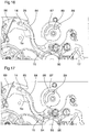
- This device comprises (cf. figure 16 ) a locking lever 84 held in the rest position against a stop 85 fixed to the frame 1 by a return spring 86. In its rest position the locking lever 84 is out of the path followed by the pin 14 during the change of position It thus does not interfere with the movements of the clutch rocker 6. However, the locking lever 84 can be pivoted to a position shown in FIG.
- the member which controls the pivoting of the locking lever 84 is a power reserve display wheel 87.
- the power reserve display wheel 87 comprises an arcuate opening 88 which receives a pin 89 fixed to the frame 1.
- the aperture 88 and the pin 89 define two limit positions for the power reserve display wheel 87, namely a position substantially corresponding to a fully armed state of the spring of the ringer barrel 3 and a position substantially corresponding to a completely disarmed state of the spring of the ringer barrel 3.
- the power reserve display wheel 87 carries an indicator (not shown), such as a needle, indicating the power reserve of the striking mechanism on the dial of the watch.
- the power reserve display wheel 87 is driven by the output of a differential whose two inputs are the shaft of the ringer barrel 3 and the toothing of said cylinder.
- the power reserve display wheel 87 When the alarm barrel 3 is sufficiently raised ( figure 16 ) the power reserve display wheel 87 does not act on the locking lever 84 which remains in its rest position. When the ringer barrel 3 does not contain enough energy to activate the ringer ( figure 17 ) the power reserve display wheel 87 is in an angular position such that a projecting portion 90 of this wheel 87 comes into contact with the locking lever 84 and pivots against the action of its return spring 86 to bring it into its position where it prevents the pivoting of the clutch lever 6 to its disengaged position. By the indicator carried by the power reserve display wheel 87 the user is informed that he must raise the ringer barrel 3. As soon as the ringer barrel 3 is sufficiently raised the projecting portion 90 moves away from the locking lever 84, allowing the latter to return to its rest position, out of the path of the pin 14.
- the striking mechanism comprises a device for preventing the bell from sounding when the watch is set.
- the rotation of the cams of the hours, quarters and minutes 41, 46, 51 caused by a time setting can cause damage in the striking mechanism if no device is provided to prevent the feelers 39, 44, 49 to come into contact with said cams during the time setting.
- the device used in the present invention comprises an actuable locking lever 91 by the zipper 92 of the time setting mechanism, which cooperates with the winding stem 5. When the winding stem 5 is in its pushed position the locking lever 91 is out of the way of the pin 14 carried by the rocker clutch 6 ( figure 18 ).
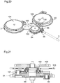
- the striking mechanism comprises a device, shown in FIGS. Figures 20 and 21 , making it possible to easily raise both the ringer barrel 3 and the barrel of the movement, designated by the reference 93.
- This device is arranged so that, when the winding stem 5 is in its pushed position, a rotation of said rod in one direction (for example clockwise) raises the barrel ring 3 and a rotation of said rod in the other direction (for example counterclockwise) back the barrel 93 some movement.
- This device comprises an input wheel 94 which can be driven in one direction or the other by the winding stem 5.
- the input wheel 94 meshes with a crown wheel 95 which itself meshes with a winding pinion 96 mounted around the winding stem 5 and driven via toothed crenellations by a sliding pinion 97 (visible on the figure 18 ) The rotation of the winding shaft 5.
- the input wheel 94 carries on each of its two faces at least one pawl.
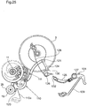
- the pawls 98 carried by the lower face of the input wheel 94 (cf. figures 21 and 22 ) cooperate with a toothing with wolf teeth of a pinion 99 integral with a first output wheel 100.
- the pawls 101 carried by the upper face of the input wheel 94 (cf. figures 21 and 23 ) cooperate with a wolf teeth of a pinion gear 102 integral with a second output wheel 103.
- the first output wheel 100 is a winding wheel of the ringer barrel 3. It meshes with the ratchet 104 of the ringer barrel 3 via a reference 105.
- the second output wheel 103 is a winding wheel of the cylinder 93 of the movement. It meshes with the ratchet 106 of the barrel 93 of the movement via referrals 107, 108. Thanks to the catches 98, 101 the first and second output wheels 100, 103 rotate only in one direction, and the direction of rotation of the first output wheel 100 is opposed to that of the second output wheel 103.
- the input wheel 94 When the input wheel 94 is driven by the winding stem 5 in a first direction, it drives with its pawls 98 the pinion 99 and therefore the first output wheel 100 to raise the ringer barrel 3.
- this winding device barrels 3, 93 is very compact in the plane of the watch since the input wheel 94 (bidirectional) and the two output wheels 100, 103 (unidirectional) are coaxial.
- the Figures 24 to 26 show a clutch device according to another embodiment.
- the clutch device included the clutch rocker 6 and pinions 8, 9 carried by this rocker.
- the clutch device illustrated in Figures 24 to 26 comprises a rocker 110 and a differential gear 111 placed between the ringer barrel 3 and the ringer shaft 11.
- the differential gear 111 comprises (cf. figure 26 ), arranged in a coaxial manner, a sun gear 112 secured to a connecting wheel 113 which meshes with the striking barrel 3, a planet carrier 114 and a sun gear 115.
- the sun gear 112 constitutes the input of the differential 111 It comprises an internal toothing which meshes with at least one (preferably three) satellite 116 carried by the planet carrier 114.
- the sun wheel 112 could be a pinion meshing with its peripheral teeth with the satellite or satellites 116.
- Each satellite 116 is coaxial and integral with a satellite 117 located on the other side of the planet carrier 114.
- Each satellite 117 meshes with the sun gear 115.
- the latter which constitutes the output of the differential 111, meshes, for example by through a reference 118, with the pinion 10 of the ringing shaft 11.
- the rocker 110 pivots at a point 119 and is subjected to the action of a return spring 110a which tends to apply against a stop 110b.
- the rocker 110 comprises, like the clutch rocker 6 of the figures 1 and 2 with its spout 18, a locking spout 120 to cooperate with the stopping star 19 secured to the wheel 2b of the ring gear 2 and thus block or unblock the ringing barrel 3.
- the rocker 110 carries a pin 121 to cooperate with the bell release lever 15 illustrated in FIGS. figures 3 and 4 or, alternatively, with a ring triggering member 122 which will be described later.
- the flip-flop 110 further carries a locking pin 123 which, depending on the position of the rocker 110, is engaged in a peripheral toothing of the planet carrier 114 or is disengaged from this toothing. More specifically, in a first position, or engaged position, of the rocker 110, the locking nose 120 does not block the ringer barrel 3 while the locking pin 123 engaged in the toothing of the planet carrier 114 blocks the latter.
- the ringing barrel 3 can therefore rotate and drive, via the connecting wheel 113, the input wheel 112 which, through its internal toothing and satellites 116-117, rotates the sun gear. 115 so the ringing tree 11.
- the locking nose 120 blocks the ringer barrel 3 while the locking finger 123 does not block the carrier 114.
- the wheel input 112 is too.
- the planet carrier 114 being free to rotate, the satellites 116-117 can drive it by rolling on the internal toothing of the input wheel 112.
- the ringing shaft 11 is thus decoupled from the ringing barrel 3 and can rotate under the action of the return springs 52, 53, 54 rakes hours, quarters and minutes 34, 35, 36 by rotating the reference 118, the sun gear 115 and the carrier 114.
- the second configuration that is to say the one where the blocking finger 123 does not block the planet carrier 114 and where the locking nose 120 blocks the ringer barrel 3, corresponds to the triggering phase triggered by actuation of the ringing trip lever 15 or the ring triggering member 122 which releases the rocker 110 and its return spring 110a.
- the first configuration that is to say the one where the blocking finger 123 blocks the planet carrier 114 and where the blocking nose 120 does not block the ringer barrel 3, corresponds to the ring phase following the taking of information.
- the blocking finger 123 is in the form of an insert attached to the rocker 110. However, alternatively, it could be in one piece with the rocker 110, as is preferably the beak blocking 120.
- the ring triggering device 122 which, in a variant, replaces the ringing trip lever 15 illustrated in FIGS. figures 3 and 4 , results from a decomposition of the lever 15 into two parts. More precisely, the bell triggering device 122 comprises two levers 124, 125 pivoting respectively at points 126, 127 and on which return springs 128, 129 respectively act tending to apply the levers 124, 125 against stops 130, 131.
- the lever 125 called the "control lever" is controlled by the tube 15a (cf. figures 3 and 4 ) in the same way as it was 15.
- the lever 124 fulfills the function of the end part of the striking trip lever 15, that is to say that of cooperating with the pin 121 for hold the rocker 110 in its engaged position.
- the control lever 125 includes a retractable spout 132 which contacts a spout 133 of the trigger lever 124 when the control lever 125 is actuated, to pivot the trigger lever 124 against the action of its return spring 128 and thus release the rocker 110.
- the spout 132 loses contact with the spout 133 and the trigger lever 124 therefore immediately returns to its initial position under the action of its spring.
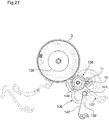
- the figures 27 and 28 show a clutch device according to yet another embodiment.
- the clutch device illustrated in figures 27 and 28 is vertical type. It comprises a rocker 135, a vertical clutch mobile 136 located between the ringer barrel 3 and the ringer shaft 11, and a control member 137 acting on the vertical clutch mobile 136 and controlled itself by the toggle 135.
- the latch 135 carries a pin 138 and a locking nose 139 having the same function, respectively, as the pin 121 and the locking nose 120 illustrated in FIG. figure 24 .
- the flip-flop 135 also carries an abutment finger 140 and a control finger 141. Like the flip-flop 110, the flip-flop 135 is subjected to the action of a return spring 142 which tends to apply against a stop (not shown).
- the vertical clutch mobile 136 comprises, arranged in a coaxial manner, a first wheel 143 which meshes with the ringer barrel 3, a second wheel 144 which meshes with the pinion 10 of the ringer shaft 11, a third wheel 145 with Breguet toothing 145a, this third wheel 145 being fixed to the second wheel 144, and a fourth gear 146 to Breguet gear 146a, this fourth wheel 146 being integral in rotation, but free in axial translation, relative to the first wheel 143.
- a spring 147 tends to apply the Breguet teeth 146a of the fourth wheel 146 against the Breguet toothing 145a of the third wheel 145 to rotationally fasten the first wheel 143 and the second wheel 144 and thus couple the ringer barrel 3 to the shaft of ringtone 11.
- the control member 137 comprises a spring 148 and, fixed to the free end of the spring 148, a fork 149 whose two teeth 150 (only one of these teeth is visible in the drawing) can come symmetrically against a flange 151 of the fourth wheel 146, to axially move the fourth wheel 146 against the action of the spring 147, during a bending of the spring 148.
- the bending of the spring 148, and thus the axial displacement of the fourth wheel 146 are controlled by the control finger 141 of the latch 135 which acts on an inclined plane 152 of the fork 149.
- the control member 137 may be in one piece.
- the flip-flop 135 can take a first position, corresponding to the position illustrated in FIGS. figures 27 and 28 , and a second position (not shown).
- the control finger 141 leaves the fork 149 in the rest position where it does not touch the fourth wheel 146, and the locking nose 139 does not block the ringer barrel 3.
- This first position corresponds to the engaged state of the clutch device, which allows the ringing phase consecutive information taking to unfold.
- the control finger 141 cooperates with the inclined plane 152 to bend the spring 148 and the fourth wheel 146 is thus released from the Breguet toothing 145a of the third wheel 145 by the fork 149.
- the second wheel 144 is free to rotate relative to the first wheel 143, which is blocked by the action of the locking nose 139 on the star 19.
- This second position of the latch 135 corresponds to the disengaged state of the clutch device, allowing the information taking phase to unfold.
- Breguet teeth 145a, 146a The unidirectional nature of Breguet teeth 145a, 146a is not used in the present invention.
- the wolf-like shape of these teeth 145a, 146a facilitates the clutch, avoiding the risk of blockage that can cause tip-to-tip contact of the teeth of the wheels 145 and 146.
- the Breguet teeth 145a, 146a can be replaced. by conventional vertical teeth (bidirectional).
- the stop finger 140 of the rocker 135 is placed under the fourth wheel 146, as shown in FIG. figure 28 when the latch 135 is in its first position.
- This stop finger 140 prevents the fourth wheel 146 from losing contact with the third wheel 145, despite the action exerted by the spring 147, in the event of shock suffered by the watch.
- the flip-flop 135 serves three functions: blocking / unlocking the ringer barrel 3, controlling the clutch / clutch and preventing disengagement in the event of an impact.
Landscapes
- Physics & Mathematics (AREA)
- General Physics & Mathematics (AREA)
- Transmission Devices (AREA)
- Soil Working Implements (AREA)
- Mechanical Operated Clutches (AREA)
- Measurement Of Unknown Time Intervals (AREA)
Claims (15)
- Schlagwerkmechanismus für eine Uhr, der Folgendes umfasst:- mindestens eine Tonfeder (29, 30),- eine Betätigungsvorrichtung (11, 20 bis 28, 31 bis 62) zum Betätigen der Tonfeder/n,- ein Schlagwerk-Federhaus (3),- eine Kupplungsvorrichtung mit Wippe (6; 110; 135) zum Kuppeln der Betätigungsvorrichtung (11, 20 bis 28, 31 bis 62) mit dem Schlagwerk-Federhaus (3), wobei die Wippe (6; 110; 135) der Kupplungsvorrichtung eingerichtet ist, um sich zwischen einer ersten Stellung, in der die Betätigungsvorrichtung (11, 20 bis 28, 31 bis 62) an dem Schlagwerk-Federhaus (3) gekuppelt ist, und einer zweiten Stellung zu drehen, in der die Betätigungsvorrichtung (11, 20 bis 28, 31 bis 62) von dem Schlagwerk-Federhaus (3) entkuppelt ist, und- eine Sperrvorrichtung (18, 60; 120; 139) zum Sperren des Schlagwerk-Federhauses (3),dadurch gekennzeichnet, dass die Sperrvorrichtung ein Sperrorgan (18; 120; 139) umfasst, das fest mit der Wippe (6; 110; 135) verbunden ist und derart eingerichtet ist, dass es das Schlagwerk-Federhaus (3) sperrt, wenn die Wippe (6, 110; 135) sich in der zweiten Stellung befindet, und es das Schlagwerk-Federhaus (3) nicht sperrt, wenn die Wippe (6; 110; 135) sich in der ersten Stellung befindet.
- Schlagwerkmechanismus nach Anspruch 1, dadurch gekennzeichnet, dass das Sperrorgan (18; 120; 139) einteilig mit der Wippe (6; 110; 135) ist.
- Schlagwerkmechanismus nach Anspruch 1 oder 2, dadurch gekennzeichnet, dass das Sperrorgan (18; 120; 139) ein Schnabel ist.
- Schlagwerkmechanismus nach einem der Ansprüche 1 bis 3, dadurch gekennzeichnet, dass das Sperrorgan (18; 120; 139) eingerichtet ist, um mit einem gezahnten Organ (19) zusammenzuwirken, das kinematisch mit dem Schlagwerk-Federhaus (3) verbunden ist.
- Schlagwerkmechanismus nach einem der Ansprühe 1 bis 4, dadurch gekennzeichnet, dass die Kupplungsvorrichtung ein/en Kupplungstrieb oder -rad (9) umfasst, der/das auf der Wippe (6) gelagert ist, wobei dieser/dieses Kupplungstrieb oder -rad (9) die Betätigungsvorrichtung (11, 20 bis 28, 31 bis 62) mit dem Schlagwerk-Federhaus (3) kuppelt, wenn die Wippe (6) sich in der ersten Stellung befindet und die Betätigungsvorrichtung (11, 20 bis 28, 31 bis 62) nicht mit dem Schlagwerk-Federhaus (3) koppelt, wenn die Wippe (6) sich in der zweiten Stellung befindet.
- Schlagwerkmechanismus nach einem der Ansprüche 1 bis 4, dadurch gekennzeichnet, dass die Kupplungsvorrichtung ein Differentialgetriebe (111) umfasst, das zwischen dem Schlagwerk-Federhaus (3) und der Betätigungsvorrichtung (11, 20 bis 28, 31 bis 62) angeordnet ist und auf die ein zweites Sperrorgan (123) einwirken kann, das durch die Wippe (110) getragen wird.
- Schlagwerkmechanismus nach einem der Ansprüche 1 bis 4, dadurch gekennzeichnet, dass die Kupplungsvorrichtung ein vertikales Kupplungsdrehteil (136) umfasst, das zwischen dem Schlagwerk-Federhaus (3) und der Betätigungsvorrichtung (11, 20 bis 28, 31 bis 62) angeordnet ist und ein Element (146) umfasst, das entlang einer Achse des vertikalen Kupplungsdrehteils (136) verlagert werden kann, um die Kupplungsvorrichtung von einem eingekuppelten Zustand in einen ausgekuppelten Zustand und umgekehrt übergehen zu lassen, wobei die Verlagerung des Elements (146) durch die Wippe (135) gesteuert werden kann.
- Schlagwerkmechanismus nach Anspruch 7, dadurch gekennzeichnet, dass die Wippe (135) ein Anschlagorgan (140) trägt, das eingerichtet ist, um bei einem Stoß eine Verlagerung des Elements (146) gegen die Wirkung einer Rückholfeder (147) zu verhindern, der das Element (146) unterworfen ist, wenn die Wippe (135) sich in ihrer ersten Stellung befindet.
- Schlagwerkmechanismus nach einem der Ansprüche 1 bis 8, dadurch gekennzeichnet, dass die Sperrvorrichtung (18; 60; 120; 139) ein zusätzliches Sperrorgan (60) umfasst, das die Form eines Anschlags aufweist, gegen den ein Stundenrechen (34) der Betätigungsvorrichtung unter der Wirkung des Schlagwerk-Federhauses (3) am Ende des Schlagens aufliegt.
- Schlagwerkmechanismus nach einem der Ansprüche 1 bis 9, dadurch gekennzeichnet, dass das Schlagwerk-Federhaus (3) über ein Schlagwerk-Räderwerk (2) mit einem Regulator (4) verbunden ist.
- Schlagwerkmechanismus nach einem der Ansprüche 1 bis 10, dadurch gekennzeichnet, dass die Wippe (6; 110; 135) ein hervorstehendes Element (14; 121; 138) trägt, das, wenn der Schlagwerkmechanismus sich im Ruhezustand befindet, durch eine Rückholfeder (13; 110a, 142) der Wippe (6; 110; 135) gegen einen Auslösungshebel (15; 124) in Auflage gehalten wird, wobei dieser Auslösungshebel (15; 124) durch ein manuelles Betätigungsorgan gedreht werden kann, um das hervorstehende Element (14; 121; 138) und mit ihm die Wippe (6; 110; 135) freizugeben und die Wippe (6; 110; 135) unter der Wirkung ihrer Rückholfeder (13; 110a; 142) von ihrer ersten Stellung in ihre zweite Stellung übergehen zu lassen und somit das Schlagwerk auszulösen.
- Schlagwerkmechanismus nach Anspruch 11, dadurch gekennzeichnet, dass es ferner einen ersten Sperrhebel (84) umfasst, der angeordnet ist, um dem hervorstehenden Element (14; 121; 138) als Anschlag zu dienen und die Freigabe des hervorstehenden Elements (14; 121; 138) zu verhindern, wenn die in dem Schlagwerk-Federhaus (3) akkumulierte Energie niedriger als ein vorbestimmter Wert ist.
- Schlagwerkmechanismus nach Anspruch 12, dadurch gekennzeichnet, dass der erste Sperrhebel (84) eingerichtet ist, um durch ein Schlagwerk-Gangreserve-Anzeigerad (87) gesteuert zu werden.
- Schlagwerkmechanismus nach einem der Ansprüche 11 bis 13, dadurch gekennzeichnet, dass es ferner einen zweiten Sperrhebel (91) umfasst, der eingerichtet ist, um dem hervorstehenden Element (14; 121; 138) als Anschlag zu dienen und die Freigabe des hervorstehenden Elements (14; 121; 138) zu verhindern, wenn eine Aufzugwelle (5) der Uhr sich in einer Zeigerstellungsposition befindet.
- Uhr, die einen Schlagwerkmechanismus nach einem der Ansprüche 1 bis 14 und ein Uhrwerk umfasst, dadurch gekennzeichnet, dass das Uhrwerk sein eigenes Federhaus (93) umfasst, und dadurch, dass eine Vorrichtung vorgesehen ist, die das Aufziehen des Schlagwerk-Federhauses (3) durch eine Drehung einer Aufzugwelle (5) in einer Richtung und das Aufziehen des Federhauses (93) des Uhrwerks durch eine Drehung der Aufzugwelle (5) in die andere Richtung ermöglicht, wobei die Vorrichtung ein Antriebsrad (94), das eingerichtet ist, um durch die Aufzugwelle (5) in die eine oder die andere Richtung angetrieben zu werden, mindestens einen ersten Sperrkegel (98), der durch eine der zwei Seiten des Antriebsrads (94) getragen wird, mindestens einen zweiten Sperrkegel (101), der durch die andere von den zwei Seiten des Antriebsrads (94) getragen wird, einen ersten Trieb (99), der koaxial zum Antriebsrad (94) ist und eine unidirektionale Zahnung umfasst, die mit dem ersten Sperrkegel (98) zusammenwirkt, einen zweiten Trieb (102), der koaxial mit dem Antriebsrad (94) ist und eine unidirektionale Zahnung umfasst, die mit dem zweiten Sperrkegel (101) zusammenwirkt, ein erstes Abtriebsrad (100), das fest mit dem ersten Trieb (99) verbunden ist und kinematisch mit dem Sperrrad (104) des Schlagwerk-Federhauses (3) verbunden ist, und ein zweites Abtriebsrad (103) umfasst, das fest mit dem zweiten Trieb (102) verbunden ist und kinematisch mit dem Sperrrad (106) des Federhauses (93) des Uhrwerks verbunden ist.
Applications Claiming Priority (2)
| Application Number | Priority Date | Filing Date | Title |
|---|---|---|---|
| EP14155761 | 2014-02-19 | ||
| PCT/EP2015/053123 WO2015124510A1 (fr) | 2014-02-19 | 2015-02-13 | Mecanisme de sonnerie pour une piece d'horlogerie |
Publications (2)
| Publication Number | Publication Date |
|---|---|
| EP3108307A1 EP3108307A1 (de) | 2016-12-28 |
| EP3108307B1 true EP3108307B1 (de) | 2018-09-19 |
Family
ID=50114306
Family Applications (1)
| Application Number | Title | Priority Date | Filing Date |
|---|---|---|---|
| EP15704544.4A Active EP3108307B1 (de) | 2014-02-19 | 2015-02-13 | Schlagwerkvorrichtung für eine uhr |
Country Status (4)
| Country | Link |
|---|---|
| EP (1) | EP3108307B1 (de) |
| JP (1) | JP6534002B2 (de) |
| CN (1) | CN106030421B (de) |
| WO (1) | WO2015124510A1 (de) |
Cited By (1)
| Publication number | Priority date | Publication date | Assignee | Title |
|---|---|---|---|---|
| EP3825781A1 (de) | 2019-11-20 | 2021-05-26 | Chopard Technologies SA | Schlagwerkmechanismus für uhr |
Families Citing this family (3)
| Publication number | Priority date | Publication date | Assignee | Title |
|---|---|---|---|---|
| EP3575886B1 (de) * | 2018-05-28 | 2021-03-10 | Blancpain SA | Uhr mit schlagwerk und einschaltsicherung |
| CH715535B1 (fr) * | 2018-11-12 | 2021-12-30 | Richemont Int Sa | Mécanisme de sonnerie. |
| EP4350449A1 (de) | 2022-10-06 | 2024-04-10 | Montres Jaquet Droz SA | Punktierbares uhrenmodul mit automatischer verriegelung |
Family Cites Families (7)
| Publication number | Priority date | Publication date | Assignee | Title |
|---|---|---|---|---|
| CH689337A5 (fr) * | 1996-09-03 | 1999-02-26 | Patek Philippe Sa | Pièce d'horlogerie à carillon. |
| ATE395639T1 (de) * | 2005-03-31 | 2008-05-15 | Zenith Internat Sa | Repetieruhr mit einem minutenrepetiermechanismus |
| EP1760554A1 (de) * | 2005-09-01 | 2007-03-07 | Montres Journe S.A. | Uhr mit einem Schlagwerk |
| EP1925995B1 (de) * | 2006-11-21 | 2014-06-18 | Christophe Claret Engineering S.A. | Schlagwerk |
| EP1925997B1 (de) * | 2006-11-21 | 2013-02-27 | Manufacture Claret SA | Schlagwerk |
| EP2339413B1 (de) * | 2009-12-22 | 2012-09-12 | The Swatch Group Research and Development Ltd. | Uhrwerk, das mit einem Vibrationswecker ausgestattet ist |
| CH703406B1 (fr) * | 2010-07-08 | 2015-04-30 | Complitime Sa | Pièce d'horlogerie comprenant un mécanisme de sonnerie. |
-
2015
- 2015-02-13 CN CN201580009501.9A patent/CN106030421B/zh active Active
- 2015-02-13 WO PCT/EP2015/053123 patent/WO2015124510A1/fr not_active Ceased
- 2015-02-13 EP EP15704544.4A patent/EP3108307B1/de active Active
- 2015-02-13 JP JP2016529878A patent/JP6534002B2/ja active Active
Non-Patent Citations (1)
| Title |
|---|
| None * |
Cited By (1)
| Publication number | Priority date | Publication date | Assignee | Title |
|---|---|---|---|---|
| EP3825781A1 (de) | 2019-11-20 | 2021-05-26 | Chopard Technologies SA | Schlagwerkmechanismus für uhr |
Also Published As
| Publication number | Publication date |
|---|---|
| JP6534002B2 (ja) | 2019-06-26 |
| CN106030421B (zh) | 2018-11-20 |
| CN106030421A (zh) | 2016-10-12 |
| WO2015124510A1 (fr) | 2015-08-27 |
| JP2017516064A (ja) | 2017-06-15 |
| EP3108307A1 (de) | 2016-12-28 |
Similar Documents
| Publication | Publication Date | Title |
|---|---|---|
| EP2453322B1 (de) | Schneller Korrektor einer Zeitgrößenanzeige für Uhr | |
| EP2498147B1 (de) | Schlagwerksblock und Antriebsmechanismus für Weckerwerk für Uhren mit Schlagwerken | |
| EP3108306B1 (de) | Schlagwerkvorrichtung für eine uhr | |
| CH704591A2 (fr) | Mécanisme de sécurité contre des manipulations intempestives de commande de répétition minutes. | |
| EP1925995B1 (de) | Schlagwerk | |
| CH704625B1 (fr) | Mécanisme de sonnerie de réveil par la grande sonnerie. | |
| EP2226688B1 (de) | Uhr | |
| WO2015124510A1 (fr) | Mecanisme de sonnerie pour une piece d'horlogerie | |
| EP3159753B1 (de) | Zeitgeber für einstellbare weckwiederholung für mechanische armbanduhr | |
| CH703635A2 (fr) | Pièce d'horlogerie munie d'un mécanisme de répétition ou de sonnerie et d'un mécanisme d'alarme. | |
| EP1925997A1 (de) | Schlagwerk | |
| EP4320487A1 (de) | Uhr mit verstärker- und alarmfunktionen | |
| CH705439B1 (fr) | Mécanisme de commande d'un chronographe. | |
| EP1760545A1 (de) | Uhr mit einem Schlagwerk | |
| EP2281222B1 (de) | Anzeigevorrichtung | |
| CH709152A2 (fr) | Pièce d'horlogerie comportant un mécanisme de sonnerie. | |
| EP1760548B1 (de) | Uhr mit einer Vorrichtung zur Zeitangabe durch Läutwerk | |
| EP4071562B1 (de) | Schlagwerkmechanismus und diesen umfassende uhr | |
| EP3825781B1 (de) | Schlagwerkmechanismus für uhr | |
| CH709151A2 (fr) | Pièce d'horlogerie comportant un barillet de sonnerie. | |
| EP4071561B1 (de) | Repetitionsuhr | |
| EP1760554A1 (de) | Uhr mit einem Schlagwerk | |
| EP1760550A1 (de) | Uhr mit grossem Schlagwerk | |
| EP1760544A1 (de) | Vorrichtung zur Anzeige von Federspannung | |
| EP1760551A1 (de) | Uhr mit Grossem Schlagwerk |
Legal Events
| Date | Code | Title | Description |
|---|---|---|---|
| PUAI | Public reference made under article 153(3) epc to a published international application that has entered the european phase |
Free format text: ORIGINAL CODE: 0009012 |
|
| STAA | Information on the status of an ep patent application or granted ep patent |
Free format text: STATUS: REQUEST FOR EXAMINATION WAS MADE |
|
| 17P | Request for examination filed |
Effective date: 20160614 |
|
| AK | Designated contracting states |
Kind code of ref document: A1 Designated state(s): AL AT BE BG CH CY CZ DE DK EE ES FI FR GB GR HR HU IE IS IT LI LT LU LV MC MK MT NL NO PL PT RO RS SE SI SK SM TR |
|
| AX | Request for extension of the european patent |
Extension state: BA ME |
|
| DAX | Request for extension of the european patent (deleted) | ||
| GRAP | Despatch of communication of intention to grant a patent |
Free format text: ORIGINAL CODE: EPIDOSNIGR1 |
|
| STAA | Information on the status of an ep patent application or granted ep patent |
Free format text: STATUS: GRANT OF PATENT IS INTENDED |
|
| INTG | Intention to grant announced |
Effective date: 20180605 |
|
| GRAS | Grant fee paid |
Free format text: ORIGINAL CODE: EPIDOSNIGR3 |
|
| GRAA | (expected) grant |
Free format text: ORIGINAL CODE: 0009210 |
|
| STAA | Information on the status of an ep patent application or granted ep patent |
Free format text: STATUS: THE PATENT HAS BEEN GRANTED |
|
| AK | Designated contracting states |
Kind code of ref document: B1 Designated state(s): AL AT BE BG CH CY CZ DE DK EE ES FI FR GB GR HR HU IE IS IT LI LT LU LV MC MK MT NL NO PL PT RO RS SE SI SK SM TR |
|
| REG | Reference to a national code |
Ref country code: GB Ref legal event code: FG4D Free format text: NOT ENGLISH |
|
| REG | Reference to a national code |
Ref country code: CH Ref legal event code: EP |
|
| REG | Reference to a national code |
Ref country code: AT Ref legal event code: REF Ref document number: 1043955 Country of ref document: AT Kind code of ref document: T Effective date: 20181015 |
|
| REG | Reference to a national code |
Ref country code: IE Ref legal event code: FG4D Free format text: LANGUAGE OF EP DOCUMENT: FRENCH |
|
| REG | Reference to a national code |
Ref country code: DE Ref legal event code: R096 Ref document number: 602015016601 Country of ref document: DE |
|
| REG | Reference to a national code |
Ref country code: CH Ref legal event code: NV Representative=s name: MICHELI AND CIE SA, CH |
|
| REG | Reference to a national code |
Ref country code: NL Ref legal event code: MP Effective date: 20180919 |
|
| PG25 | Lapsed in a contracting state [announced via postgrant information from national office to epo] |
Ref country code: NO Free format text: LAPSE BECAUSE OF FAILURE TO SUBMIT A TRANSLATION OF THE DESCRIPTION OR TO PAY THE FEE WITHIN THE PRESCRIBED TIME-LIMIT Effective date: 20181219 Ref country code: BG Free format text: LAPSE BECAUSE OF FAILURE TO SUBMIT A TRANSLATION OF THE DESCRIPTION OR TO PAY THE FEE WITHIN THE PRESCRIBED TIME-LIMIT Effective date: 20181219 Ref country code: SE Free format text: LAPSE BECAUSE OF FAILURE TO SUBMIT A TRANSLATION OF THE DESCRIPTION OR TO PAY THE FEE WITHIN THE PRESCRIBED TIME-LIMIT Effective date: 20180919 Ref country code: RS Free format text: LAPSE BECAUSE OF FAILURE TO SUBMIT A TRANSLATION OF THE DESCRIPTION OR TO PAY THE FEE WITHIN THE PRESCRIBED TIME-LIMIT Effective date: 20180919 Ref country code: GR Free format text: LAPSE BECAUSE OF FAILURE TO SUBMIT A TRANSLATION OF THE DESCRIPTION OR TO PAY THE FEE WITHIN THE PRESCRIBED TIME-LIMIT Effective date: 20181220 Ref country code: FI Free format text: LAPSE BECAUSE OF FAILURE TO SUBMIT A TRANSLATION OF THE DESCRIPTION OR TO PAY THE FEE WITHIN THE PRESCRIBED TIME-LIMIT Effective date: 20180919 Ref country code: LT Free format text: LAPSE BECAUSE OF FAILURE TO SUBMIT A TRANSLATION OF THE DESCRIPTION OR TO PAY THE FEE WITHIN THE PRESCRIBED TIME-LIMIT Effective date: 20180919 |
|
| REG | Reference to a national code |
Ref country code: LT Ref legal event code: MG4D |
|
| PG25 | Lapsed in a contracting state [announced via postgrant information from national office to epo] |
Ref country code: AL Free format text: LAPSE BECAUSE OF FAILURE TO SUBMIT A TRANSLATION OF THE DESCRIPTION OR TO PAY THE FEE WITHIN THE PRESCRIBED TIME-LIMIT Effective date: 20180919 Ref country code: HR Free format text: LAPSE BECAUSE OF FAILURE TO SUBMIT A TRANSLATION OF THE DESCRIPTION OR TO PAY THE FEE WITHIN THE PRESCRIBED TIME-LIMIT Effective date: 20180919 Ref country code: LV Free format text: LAPSE BECAUSE OF FAILURE TO SUBMIT A TRANSLATION OF THE DESCRIPTION OR TO PAY THE FEE WITHIN THE PRESCRIBED TIME-LIMIT Effective date: 20180919 |
|
| REG | Reference to a national code |
Ref country code: AT Ref legal event code: MK05 Ref document number: 1043955 Country of ref document: AT Kind code of ref document: T Effective date: 20180919 |
|
| PG25 | Lapsed in a contracting state [announced via postgrant information from national office to epo] |
Ref country code: EE Free format text: LAPSE BECAUSE OF FAILURE TO SUBMIT A TRANSLATION OF THE DESCRIPTION OR TO PAY THE FEE WITHIN THE PRESCRIBED TIME-LIMIT Effective date: 20180919 Ref country code: RO Free format text: LAPSE BECAUSE OF FAILURE TO SUBMIT A TRANSLATION OF THE DESCRIPTION OR TO PAY THE FEE WITHIN THE PRESCRIBED TIME-LIMIT Effective date: 20180919 Ref country code: IS Free format text: LAPSE BECAUSE OF FAILURE TO SUBMIT A TRANSLATION OF THE DESCRIPTION OR TO PAY THE FEE WITHIN THE PRESCRIBED TIME-LIMIT Effective date: 20190119 Ref country code: NL Free format text: LAPSE BECAUSE OF FAILURE TO SUBMIT A TRANSLATION OF THE DESCRIPTION OR TO PAY THE FEE WITHIN THE PRESCRIBED TIME-LIMIT Effective date: 20180919 Ref country code: ES Free format text: LAPSE BECAUSE OF FAILURE TO SUBMIT A TRANSLATION OF THE DESCRIPTION OR TO PAY THE FEE WITHIN THE PRESCRIBED TIME-LIMIT Effective date: 20180919 Ref country code: PL Free format text: LAPSE BECAUSE OF FAILURE TO SUBMIT A TRANSLATION OF THE DESCRIPTION OR TO PAY THE FEE WITHIN THE PRESCRIBED TIME-LIMIT Effective date: 20180919 Ref country code: CZ Free format text: LAPSE BECAUSE OF FAILURE TO SUBMIT A TRANSLATION OF THE DESCRIPTION OR TO PAY THE FEE WITHIN THE PRESCRIBED TIME-LIMIT Effective date: 20180919 Ref country code: IT Free format text: LAPSE BECAUSE OF FAILURE TO SUBMIT A TRANSLATION OF THE DESCRIPTION OR TO PAY THE FEE WITHIN THE PRESCRIBED TIME-LIMIT Effective date: 20180919 Ref country code: AT Free format text: LAPSE BECAUSE OF FAILURE TO SUBMIT A TRANSLATION OF THE DESCRIPTION OR TO PAY THE FEE WITHIN THE PRESCRIBED TIME-LIMIT Effective date: 20180919 |
|
| PG25 | Lapsed in a contracting state [announced via postgrant information from national office to epo] |
Ref country code: SK Free format text: LAPSE BECAUSE OF FAILURE TO SUBMIT A TRANSLATION OF THE DESCRIPTION OR TO PAY THE FEE WITHIN THE PRESCRIBED TIME-LIMIT Effective date: 20180919 Ref country code: SM Free format text: LAPSE BECAUSE OF FAILURE TO SUBMIT A TRANSLATION OF THE DESCRIPTION OR TO PAY THE FEE WITHIN THE PRESCRIBED TIME-LIMIT Effective date: 20180919 Ref country code: PT Free format text: LAPSE BECAUSE OF FAILURE TO SUBMIT A TRANSLATION OF THE DESCRIPTION OR TO PAY THE FEE WITHIN THE PRESCRIBED TIME-LIMIT Effective date: 20190119 |
|
| REG | Reference to a national code |
Ref country code: DE Ref legal event code: R097 Ref document number: 602015016601 Country of ref document: DE |
|
| PLBE | No opposition filed within time limit |
Free format text: ORIGINAL CODE: 0009261 |
|
| STAA | Information on the status of an ep patent application or granted ep patent |
Free format text: STATUS: NO OPPOSITION FILED WITHIN TIME LIMIT |
|
| PG25 | Lapsed in a contracting state [announced via postgrant information from national office to epo] |
Ref country code: DK Free format text: LAPSE BECAUSE OF FAILURE TO SUBMIT A TRANSLATION OF THE DESCRIPTION OR TO PAY THE FEE WITHIN THE PRESCRIBED TIME-LIMIT Effective date: 20180919 |
|
| 26N | No opposition filed |
Effective date: 20190620 |
|
| PG25 | Lapsed in a contracting state [announced via postgrant information from national office to epo] |
Ref country code: SI Free format text: LAPSE BECAUSE OF FAILURE TO SUBMIT A TRANSLATION OF THE DESCRIPTION OR TO PAY THE FEE WITHIN THE PRESCRIBED TIME-LIMIT Effective date: 20180919 Ref country code: LU Free format text: LAPSE BECAUSE OF NON-PAYMENT OF DUE FEES Effective date: 20190213 Ref country code: MC Free format text: LAPSE BECAUSE OF FAILURE TO SUBMIT A TRANSLATION OF THE DESCRIPTION OR TO PAY THE FEE WITHIN THE PRESCRIBED TIME-LIMIT Effective date: 20180919 |
|
| REG | Reference to a national code |
Ref country code: BE Ref legal event code: MM Effective date: 20190228 |
|
| REG | Reference to a national code |
Ref country code: IE Ref legal event code: MM4A |
|
| PG25 | Lapsed in a contracting state [announced via postgrant information from national office to epo] |
Ref country code: IE Free format text: LAPSE BECAUSE OF NON-PAYMENT OF DUE FEES Effective date: 20190213 |
|
| PG25 | Lapsed in a contracting state [announced via postgrant information from national office to epo] |
Ref country code: BE Free format text: LAPSE BECAUSE OF NON-PAYMENT OF DUE FEES Effective date: 20190228 |
|
| PG25 | Lapsed in a contracting state [announced via postgrant information from national office to epo] |
Ref country code: TR Free format text: LAPSE BECAUSE OF FAILURE TO SUBMIT A TRANSLATION OF THE DESCRIPTION OR TO PAY THE FEE WITHIN THE PRESCRIBED TIME-LIMIT Effective date: 20180919 |
|
| PG25 | Lapsed in a contracting state [announced via postgrant information from national office to epo] |
Ref country code: MT Free format text: LAPSE BECAUSE OF FAILURE TO SUBMIT A TRANSLATION OF THE DESCRIPTION OR TO PAY THE FEE WITHIN THE PRESCRIBED TIME-LIMIT Effective date: 20180919 |
|
| PG25 | Lapsed in a contracting state [announced via postgrant information from national office to epo] |
Ref country code: CY Free format text: LAPSE BECAUSE OF FAILURE TO SUBMIT A TRANSLATION OF THE DESCRIPTION OR TO PAY THE FEE WITHIN THE PRESCRIBED TIME-LIMIT Effective date: 20180919 |
|
| PG25 | Lapsed in a contracting state [announced via postgrant information from national office to epo] |
Ref country code: HU Free format text: LAPSE BECAUSE OF FAILURE TO SUBMIT A TRANSLATION OF THE DESCRIPTION OR TO PAY THE FEE WITHIN THE PRESCRIBED TIME-LIMIT; INVALID AB INITIO Effective date: 20150213 |
|
| PG25 | Lapsed in a contracting state [announced via postgrant information from national office to epo] |
Ref country code: MK Free format text: LAPSE BECAUSE OF FAILURE TO SUBMIT A TRANSLATION OF THE DESCRIPTION OR TO PAY THE FEE WITHIN THE PRESCRIBED TIME-LIMIT Effective date: 20180919 |
|
| REG | Reference to a national code |
Ref country code: CH Ref legal event code: U11 Free format text: ST27 STATUS EVENT CODE: U-0-0-U10-U11 (AS PROVIDED BY THE NATIONAL OFFICE) Effective date: 20260301 |
|
| PGFP | Annual fee paid to national office [announced via postgrant information from national office to epo] |
Ref country code: GB Payment date: 20260219 Year of fee payment: 12 |
|
| PGFP | Annual fee paid to national office [announced via postgrant information from national office to epo] |
Ref country code: DE Payment date: 20260218 Year of fee payment: 12 |
|
| PGFP | Annual fee paid to national office [announced via postgrant information from national office to epo] |
Ref country code: FR Payment date: 20260218 Year of fee payment: 12 |
|
| PGFP | Annual fee paid to national office [announced via postgrant information from national office to epo] |
Ref country code: CH Payment date: 20260301 Year of fee payment: 12 |