EP4071561B1 - Repetitionsuhr - Google Patents
Repetitionsuhr Download PDFInfo
- Publication number
- EP4071561B1 EP4071561B1 EP21167136.7A EP21167136A EP4071561B1 EP 4071561 B1 EP4071561 B1 EP 4071561B1 EP 21167136 A EP21167136 A EP 21167136A EP 4071561 B1 EP4071561 B1 EP 4071561B1
- Authority
- EP
- European Patent Office
- Prior art keywords
- barrel
- alarm
- quarter
- striking
- minute
- Prior art date
- Legal status (The legal status is an assumption and is not a legal conclusion. Google has not performed a legal analysis and makes no representation as to the accuracy of the status listed.)
- Active
Links
Images






Classifications
-
- G—PHYSICS
- G04—HOROLOGY
- G04B—MECHANICALLY-DRIVEN CLOCKS OR WATCHES; MECHANICAL PARTS OF CLOCKS OR WATCHES IN GENERAL; TIME PIECES USING THE POSITION OF THE SUN, MOON OR STARS
- G04B21/00—Indicating the time by acoustic means
- G04B21/02—Regular striking mechanisms giving the full hour, half hour or quarter hour
- G04B21/14—Winding-up the striking mechanism by the clockwork; winding up the clockwork by the striking mechanism
-
- G—PHYSICS
- G04—HOROLOGY
- G04B—MECHANICALLY-DRIVEN CLOCKS OR WATCHES; MECHANICAL PARTS OF CLOCKS OR WATCHES IN GENERAL; TIME PIECES USING THE POSITION OF THE SUN, MOON OR STARS
- G04B21/00—Indicating the time by acoustic means
- G04B21/02—Regular striking mechanisms giving the full hour, half hour or quarter hour
- G04B21/04—Hour wheels; Racks or rakes; Snails or similar control mechanisms
-
- G—PHYSICS
- G04—HOROLOGY
- G04B—MECHANICALLY-DRIVEN CLOCKS OR WATCHES; MECHANICAL PARTS OF CLOCKS OR WATCHES IN GENERAL; TIME PIECES USING THE POSITION OF THE SUN, MOON OR STARS
- G04B21/00—Indicating the time by acoustic means
- G04B21/02—Regular striking mechanisms giving the full hour, half hour or quarter hour
- G04B21/12—Reiterating watches or clocks
-
- G—PHYSICS
- G04—HOROLOGY
- G04B—MECHANICALLY-DRIVEN CLOCKS OR WATCHES; MECHANICAL PARTS OF CLOCKS OR WATCHES IN GENERAL; TIME PIECES USING THE POSITION OF THE SUN, MOON OR STARS
- G04B23/00—Arrangements producing acoustic signals at preselected times
- G04B23/02—Alarm clocks
- G04B23/021—Controls (winding up the alarm; adjusting and indicating the waking time)
Definitions
- the present invention relates to a timepiece comprising a striking mechanism capable of operating at least in a repeater mode, in particular a minute repeater mode, in which it audibly indicates the current time on demand.
- repeater mechanisms are powered either by a large striking barrel that the user winds up using a winding crown when the energy reserve is exhausted after several strikes, or by a small striking barrel that is wound up before each strike by means of a lock that the user manipulates to activate the repeater.
- the repeater mechanism is only part of the striking mechanism, the latter also having, for example, a striking function in passing (so-called grande sonnerie or petite sonnerie mechanisms) or an alarm function (cf. CH 703635 ).
- the striking barrel then constitutes the energy source for the entire striking mechanism.
- the second case corresponds to striking mechanisms which only include a repeater function, as in the document EP3508925A1 , For example.
- a large striking barrel wound by a winding crown requires in practice to provide a display of its energy reserve so that the user can know when to wind it, and the user must remember to check the energy level before activating the repeater.
- the travel of the lock depends on the number of strokes to be struck so that the strike barrel is only recharged with the amount of energy necessary to sound the strike.
- the lock stops in fact as soon as an hour feeler comes into contact with an hour snail to take the information of the number of hours to be struck, which, by moving an all or nothing, triggers the catch quarter and minute information by quarter and minute parts touching quarter and minute snails under the impulse of respective return springs.
- the lock acts via a rack on the striking barrel shaft to wind the spring housed in the striking barrel drum.
- the striking barrel shaft moves in the opposite direction under the action of the striking barrel spring and, regulated by a speed regulator, winds up an hour ratchet and the quarter and minute parts to strike the current hour.
- the rack returns to its rest position at the rate imposed by the striking barrel shaft.
- the striking barrel drum for its part, always remains fixed.
- the force applied to the hour snail is that of the user. If the user exerts excessive force, this can cause breakage or cause the hour snail to turn until the hour feeler stops on the wrong step, giving false information on the number of strokes to strike.
- the present invention aims to provide a repeating timepiece which remedies, at least in part, the aforementioned drawbacks.
- a timepiece in particular a wristwatch, a pocket watch, a pendant watch or a small clock, comprising a striking mechanism capable of operating at least in a repeater mode, a striking barrel for powering the striking mechanism and a manual control member operable by the user to wind the striking barrel and activate the repeater mode, the striking barrel comprising a barrel drum, a barrel arbor and a spiral barrel spring housed in the barrel drum and coupled by its outer end to the barrel drum and by its inner end to the barrel arbor, the striking mechanism comprising at least one gong, at least one hammer for striking the at least one gong and an actuating device coupled to a first barrel element constituted by one of the barrel drum and the barrel shaft for actuating the at least one hammer, characterized in that a second barrel element constituted by the other of the barrel drum and the barrel shaft comprises a toothing with which a pawl cooperates, in that the manual control member is arranged to drive a control rack meshing, via a one-way clutch mobile
- the present invention applies equally well to striking mechanisms having a repeater function combined with a second type of striking such as an alarm or a passing strike, as to striking mechanisms having only a repeater function.
- the striking barrel can also be wound by a winding crown, the winding by said manual control member, typically a lock, then serving to preserve the power reserve of the second type of striking.
- a timepiece which in the illustrated example is a wristwatch, comprises a case 2 containing a base movement, a striking mechanism connected to the base movement, a dial 8 and indicator hands or other indicator members associated with the dial 8.
- the indicator hands typically comprise an hour indicator hand 10, a minute indicator hand 12 and a second indicator hand 14 actuated by the base movement, as well as an alarm hour hand 16.
- the winding crown 18 can occupy three axial positions: a pushed position, an intermediate position and a pulled position.
- a rotation of the winding crown 18 in the clockwise direction winds the basic movement.
- a rotation of the winding crown 18 in the clockwise or counterclockwise direction makes it possible to set an alarm time.
- a rotation of the winding crown 18 in the clockwise or counterclockwise direction makes it possible to set the current time (time of the basic movement).
- the selection pusher 20 passes coaxially through the winding crown 18 and is axially movable relative thereto. The selection pusher 20 could nevertheless be separated from the winding crown 18.
- the striking mechanism has a minute repeater operating mode and a alarm, the transition from one mode to the other being carried out by means of the selection pushbutton 20.
- an actuation of the activation lock 22 i.e. a sliding of the activation lock 22 on the periphery of the case 2 between a rest position and an end-of-travel position, causes the striking mechanism to switch from a selected minute repeater state (block a) to an activated minute repeater state (block b) by triggering the striking of the hours, quarters and minutes of the current time.
- the striking mechanism remains in the minute repeater mode until the selection pusher 20 is actuated.
- actuation of the activation lock 22 causes the striking mechanism to transition from an alarm selected state (block c), where the striking mechanism is inactive, to an alarm activated state (block d), where the striking mechanism waits for the current time to reach a determined alarm time before triggering the striking of the hours, quarters and minutes of said alarm time (block e). Once the alarm time has been struck, the striking mechanism returns to its alarm selected state (block c).
- minute repeater or alarm it is not possible to stop the chime once it has been triggered. The user must wait for the chime to end before being able to carry out a new operation on the timepiece.
- the stroke of the activation lock 22 in the alarm mode is the same as in the minute repeater mode and does not depend on the number of strokes to be sounded, as will be explained later. Furthermore, both operating modes use the same energy source consisting of a striking barrel 24 (cf. figure 2 ) independent of the barrel of the base movement.
- the base movement and the striking mechanism are mounted on a frame (not shown) classically formed of a plate and bridges.
- the basic movement (not shown) is of the traditional type. It is located on the bridge side and includes a barrel acting as a power source, a gear train, an escapement and a sprung balance or other resonator.
- the basic movement can be supplemented by an automatic winding mechanism designed to wind the barrel using the energy provided by the movements of the wearer of the timepiece.
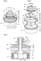
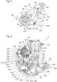
- the 24-hour strike barrel (cf. figures 4, 5, 6 And 10 ) consists of a barrel drum 52 housing a spiral barrel spring 54 and a toothing 56 secured to the barrel drum 52.
- the barrel drum 52 is traversed, in a freely rotatable manner, by a barrel shaft 58 to which the inner end of the barrel spring 54 is attached, the outer end of the barrel spring 54 being coupled to the wall of the barrel drum 52 by a sliding flange 60, as will be explained later.
- a fusee wheel 62 integral in rotation with the barrel arbor 58
- a detent ratchet 64 free in rotation relative to the barrel arbor 58 and a spring 66 (visible in the figure). figure 27 ) prevents it from moving back, and a drive plate 68 integral in rotation with the barrel shaft 58.
- the trigger ratchet 64 is held axially by two bearing screws 70 which pass through elongated holes 72 in the trigger ratchet 64 to be screwed into the drive plate 68.
- the elongated holes 72 allow limited rotation of the trigger ratchet 64 relative to the drive plate 68.
- the drive plate 68 carries a trigger pawl 74 and a return spring 76 for the trigger pawl.
- a pin 78 carried by the trigger ratchet 64 passes through an opening 80 in the drive plate 68 large enough not to hinder the rotation of the latter. This pin 78 has the function of moving the trigger pawl 74 outwards, the end of which has an inclined surface 82 for this purpose.
- the trigger pawl 74 is arranged to cooperate, by an engagement lug 84 which it comprises, with a barrel ratchet 86 free to rotate around a barrel 88 of the escapement plate 68.
- an hour ratchet 90 Around the barrel of the barrel ratchet 86 are mounted an hour ratchet 90, a rack pinion on fusee 92, a quarter piece pinion 94 and a piece control finger quarters 96.
- the hour ratchet 90, the rack pinion on fusee 92 and the quarter part control finger 96 are integral in rotation with the barrel ratchet 86.
- the quarter part pinion 94 is, itself, free in rotation relative to the barrel ratchet 86 but is controlled by the quarter part control finger 96 by means of a pin 98 carried by the quarter part pinion 94.
- the assembly 64, 68, 86, 90, 92, 94, 96 is held axially in one direction by a shoulder 100 of the barrel arbor 58 against which the drive plate 68 can bear and in the other direction by a nut 102 screwed onto one end of the barrel arbor 58.
- the assembly 64, 68, 86, 90, 92, 94, 96 is located on the dial side while the striking barrel 24 and the fusee wheel 62 are located on the bridge side.
- the assembly 64, 68, 86, 90, 92, 94, 96 constitutes a trigger fuse of the type found in grand strike mechanisms where the strike can be triggered manually (on demand) or automatically (on the fly). It makes it possible to decouple the strike barrel 24 from the parts used to actuate the hammers 40, 42 to allow the collection of information on the number of strokes to be struck and to couple the strike barrel 24 to said parts used to actuate the hammers 40, 42 after the collection of information to sound the strike.
- the barrel drum 52 by its teeth 56, meshes with the wheel 104 of a one-way clutch mobile 106 (cf. Figures 7 and 8 ).
- the pinion 108 of the one-way clutch mobile 106 coupled to the wheel 104 by a ratchet disengageable system, is engaged with a toothed sector 110 of a control rack 112 actuated by the activation lock 22.
- the control rack 112 pivots about a point 114 and has a slot 116 in which a fixed pin 118 is engaged (visible in FIG. figure 27 ) acting as a stop defining two limit positions of the control rack 112, namely a rest position and an end-of-travel position.
- a rack return spring 120 acts on the control rack 112 for the maintain in its rest position when not actuated by the activation lock 22.
- the control rack 112 serves to wind the barrel spring 54 via the barrel drum 52.
- a pawl 122 engaged in the teeth 56 under the action of a pawl return spring 123 prevents the striking barrel 24 from unwinding via the barrel drum 52.
- the control rack 112 further serves to actuate a winding pawl 124 positioned by a winding pawl spring 126 - the winding pawl 124 and the winding pawl spring 126 are visible at figure 27 - to set the trigger ratchet 64 in motion and thus disengage the trigger pawl 74, more precisely its engagement lug 84, from the teeth of the barrel ratchet 86 by means of the pin 78 carried by the trigger ratchet 64.
- the wheel 104 and the pinion 108 of the one-way clutch mobile 106 are integral in rotation in one direction and free in rotation relative to each other in the other direction.
- the movement of the control rack 112 by the activation lock 22 causes the pinion 108 to rotate in the direction in which it is secured to the wheel 104.
- the wheel 104 driven by the pinion 108 in turn drives the barrel drum 52, which arms the barrel spring 54.
- each actuation of the activation lock 22 winds the striking barrel 24.
- control rack 112 is released by the action of its spring 120 and returns to its rest position by rotating the pinion 108 but not the wheel 104 which, in this direction, is disengaged from the pinion 108 and retained by the teeth 56 itself retained by the pawl 122.
- the control rack 112 For its drive by the activation lock 22, the control rack 112 comprises an arm 128 that a pin (not shown) carried by the activation lock 22 can push against the action of the rack return spring 120 and against the action of a return spring of the activation lock 22.
- the activation lock 22 is movable between a rest position where its return spring presses it against a stop of the box 2 and an end position of travel where it is supported against the control rack 112 itself at the end of travel against the pin 118 (cf. figure 28 ).
- the one-way clutch mobile 106 (cf. figure 9 ) is for example as described in international patent application no. PCT/IB2020/060506 of the applicant.
- the wheel 104 comprises an internal toothing 132 with asymmetrical teeth which delimits a housing 134 in which there are a rigid pawl 136, a rigid drive member 138 and an elastic blade 140 connecting the rigid pawl 136 to the rigid drive member 138.
- the rigid drive member 138 is integral in rotation with the pinion 108.
- the wheel 104 is mounted loosely around the axis 142 of the pinion 108 and is made integral with the pinion 108 in one direction of rotation by the rigid pawl 136 blocked by the rigid drive member 138 against a tooth of the internal toothing 132. In the other direction of rotation, the rigid pawl 136 unlatches and thus separates the wheel 104 from the pinion 108.
- the striking barrel 24 has a sliding flange 60. It is therefore a barrel which resembles that of self-winding watches, the sliding flange 60 serving to avoid any overtension in the barrel spring 54. Indeed, unlike conventional minute repeater mechanisms where the degree of winding of the striking barrel depends on the number of strokes to be struck, the striking barrel 24 in the present invention is fully wound each time the activation lock 22 is actuation, this in order to guarantee sufficient energy for the maximum number of strokes that the striking mechanism 6 may have to sound depending on the alarm time that the user has programmed.
- This 60 sliding flange is shown in the figure 10 . It may comprise protrusions 144 cooperating with corresponding notches provided in the wall of the barrel drum 52 to index positions of the sliding flange 60 along said wall between which the sliding flange 60 can slide in the event of overtension of the barrel spring 54.
- the fusee wheel 62 is kinematically connected to the speed regulator 48 via the striking gear train 50, also called the "small gear train", which is a multiplier gear train.
- the speed regulator 48 makes it possible to regulate the rotation speed of the striking gear train 50 and the barrel arbor 58.
- a propeller 146 for locking and unlocking the striking gear train 50 is coaxial and integral with the speed regulator 48.
- the output torque of the striking gear train 50 is very low, such that a simple tangent contact on the propeller 146 is sufficient to stop the entire striking gear train 50 and the barrel arbor 58. This tangent contact is ensured by a propeller stop lever 148 when the latter is constrained by a quarter part 150 as shown in figure 11 .
- the quarter piece 150 includes on its periphery two series 152, 154 of three teeth.
- the first series 152 is intended to cause a first lifting of the quarters (not shown) raising a small hammer 42 striking a high-pitched gong 46 (cf. figures 11 And 3 ), and the second series 154 is intended to drive a second quarter lift (not shown) raising a large hammer 40 striking a low-pitched gong 44.
- the quarter piece 150 further has an internal toothing 156 engaging with the quarter piece pinion 94.
- the quarter piece quarters 150 also has a quarter feeler 158. This quarter feeler 158 is arranged to rest on the steps of a quarter snail 160 (cf.
- the quarter snail 160 is coaxial with the cannon pinion of the base movement. In addition, it carries a pin 164 which, with each turn of the cannon pinion, advances by one tooth a twelve-pointed star 166 carrying an hour snail 168.
- the barrel ratchet 86 In the rest state of the striking mechanism 6 ( minute repeater selected or alarm selected state), the barrel ratchet 86 is secured to the barrel arbor 58 by the cooperation between the trigger pawl 74 and the barrel ratchet 86, and the quarter piece 150 subjected to the action of the barrel arbor 58 via the barrel ratchet 86, the quarter piece control finger 96 and the quarter piece pinion 94 is blocked by the helix 146 in a high position, away from the quarter snail 160, against the force of the quarter piece return spring 162.
- a snail of minutes 170 (cf. figure 14 ) is coaxial and integral with the cannon-pinion. On the steps of this minute snail 170 can be supported a minute feeler 172 of a minute piece 174 to determine the number of minutes to be struck.
- the minute piece 174 is mounted on the same axis 176 as the quarter piece 150 and is subjected to the action of a minute piece return spring 178.
- the minute piece 174 is provided with a first toothed sector 180 of fourteen teeth intended to cause a lift of the minutes raising the small hammer 42.
- the minute piece 174 has a second toothed sector 182 which cooperates in a traditional manner with a minute hook 184 carried by the quarter piece 150.
- the hour ratchet 90 is intended to drive a lift of the hours raising the large hammer 40.
- the rack pinion on spindle 92 integral with the hour ratchet 90, meshes with the toothed sector 186 of a rack or hour rack 188 (cf. Figures 4 to 6 And 12 ) subjected to the action of a return spring of the hour rack 190 and which includes an hour feeler 192 capable of coming to bear on the steps of the hour snail 168 to determine the number of hours to be struck.
- a pin 194 carried by the quarter piece 150 serves to retain the hour rack 188 for a certain time during the fall of the quarter piece 150 towards the quarter snail 160.
- the quarter snail 160 and the minute snail 170 is freely mounted a surprise 196.
- a pin 198 (cf. figures 12 And 14 ) implanted in the minute snail 170 and engaged in a larger hole 200 in the surprise 196 limits the rotational mobility of the surprise 196 relative to the minute snail 170.
- the quarter snail 160 is integral with the surprise 196 and defines a spring 202 which acts on the pin 198. This spring 202 tends to angularly align the surprise 196 with the minute snail 170.
- a surprise has the function of extending the 0 step of each branch of the minute snail when no minute is to be struck, in order to prevent the minute feeler from inadvertently falling on the fourteenth step of the adjacent branch.
- Surprise 196 is activated before each strike, when the hour to be struck is an hour without a minute to be struck or an hour that slightly precedes (typically by one or two minutes) an hour without a minute to be struck, by a quarter jumper 204 which angularly offsets it relative to the minute snail 170 against the action of spring 202. After the strike, surprise 196 returns to its rest position.
- the activation of the surprise 196 does not occur when the activation lock 22 is actuated, as in a conventional minute repeater, but during the fall of the quarter pieces 150 and minutes 174 and the hour rack 188 onto their snails 160, 170, 168, more precisely during the fall of the hour rack 188.
- the quarter jumper 204 is controlled by the hour rack 188 via a pin 206 carried by the hour rack 188 and against which an arm of the quarter jumper 204 rests under the action of a quarter jumper return spring 208. Each time the hour rack 188 falls towards the hour snail 168, it authorizes the quarter jumper 204 to approach surprise 196.
- This movement of the quarter jumper 204 has most of the time no effect on surprise 196 given the angular position of the latter, but when the hour to be struck is an hour without a minute to be struck or an hour which slightly precedes an hour without a minute to be struck, the quarter jumper 204 comes into contact with surprise 196 to offset it angularly relative to the minute snail 170.
- the quarter jumper 204 is only in the path of the surprise 196 during the strike triggering phase and does not need to be lifted every quarter hour by the surprise 196 between the time when the alarm is activated by actuation of the activation lock 22 and the time when the current time coincides with the determined alarm time. Energy consumption is thus reduced.
- minute piece 174 may be very close to minute snail 170.
- the time it takes for minute piece 174 to fall until it reaches minute snail 170 may be too short to allow hour rack 188 to activate surprise 196.
- the mechanism of chime 6 is provided with a minute blocker 210 arranged to delay the fall of the minute piece 174 until the surprise 196 is activated by the hour rack 188.
- the 210 minute blocker is particularly visible at the figure 14 . It pivots around a point 212 and its rest position is defined by a pin 214 against which it rests under the action of a return spring 216.
- a first arm 218 of the minute blocker 210 serves as a stop for a pin 220 carried by the minute piece 174 to stop the minute piece 174 when the quarter piece 150, the minute piece 174 and the hour rack 188 fall.
- a second arm 222 of the minute blocker 210 is struck by the pin 206 of the hour rack 188 after the hour rack 188 has allowed the quarter jumper 204 to move towards the surprise 196 to activate it or not depending on the hour to be struck. This cooperation between the hour rack 188 and the minute blocker 210 lifts the minute blocker 210 and releases the minute piece 174 which can thus fall onto the minute snail 170 to take the information of the number of minutes to strike.
- the striking mechanism 6 includes (cf. figures 15 to 20 ) a column wheel 224 consisting of a ratchet 226, a column stage 228 and a cap 230, these three elements 226, 228, 230 being mounted integrally around a column wheel axle 232.
- the column wheel 224 is positioned by a jumper 234 cooperating with the ratchet 226. It is controlled by the selection pusher 20 via, successively, an intermediate lever 236, a control 238 and a control hook 240 (more visible in the figure) figure 36 ) engaged in the teeth of the ratchet 226.
- the ratchet 226 has twelve teeth and the column stage 228 has six columns.
- the active faces RM of the columns of the column stage 228 correspond to the minute repeater mode while the gaps AL between two columns correspond to the alarm mode.
- the cap 230 is located in the example illustrated between the ratchet 226 and the column stage 228. It has in its lower face, that is to say the face furthest from the column stage 228, a hollow 242 which surrounds the column wheel axle 232.
- the two walls which laterally delimit the hollow 242 constitute star-shaped cams for the inner wall 244 and of generally polygonal shape for the outer wall 246.
- the vertices RM of the star and the polygon are angularly aligned with the active faces RM of the columns and also correspond to the minute repeater mode.
- the zones AL of the hollow 242 between the vertices RM correspond to the alarm mode.
- the principle of the operating mode selection is to allow the quarter piece 150 to fall immediately after the activation lock 22 is actuated when the striking mechanism 6 is in the minute repeater mode, to trigger the striking of the hours, quarters and minutes of the current time, and to prevent the quarter piece 150 from falling beyond an intermediate waiting position, until the current time corresponds to the determined alarm time, when the striking mechanism 6 is in the alarm mode.
- the support of the second inclined surface 262 of the alarm triggering lever jumper 256 on the first pin 252 keeps the latter in the rotation path of the stop 264 of the quarter piece 150 and therefore prevents the quarter piece 150 from falling onto the quarter snail 160 and triggering the strike.
- the quarter piece 150 stops on the first pin 252, which corresponds to the intermediate waiting position mentioned higher. In this position, the second pin 254 is not in contact with either of the two walls 244, 246 of the recess 242 and the secondary alarm triggering rocker 248 is retained by the primary alarm triggering rocker 268 which, here, is in contact with the output cam 270 of the alarm differential 272.
- the secondary alarm triggering lever 248 is provided with a tab 274.
- the secondary alarm triggering lever 248 further comprises a finger 276 capable of cooperating with a cannon pinion nut 278, coaxial and integral with the cannon pinion of the base movement, having four notches 280 (cf. figure 21 ) representative of the quarters to be sounded in alarm mode.
- the primary alarm triggering rocker 268 comprises on its periphery two legs 282, 284 capable of interacting with the leg 274 of the secondary alarm triggering rocker 248 and an arm 286 passing under the output cam 270 of the alarm differential 272 and the end of which is surmounted by a lug 288 arranged to cooperate with this output cam 270.
- the primary alarm triggering rocker 268 is pivoted not around a physical axis but around a virtual axis by means of a flexible guide 290 suspending it from a fixed base 292.
- the alarm differential 272 is used to compare the current time with the determined alarm time.
- Two diametrically opposed notches 294 in the output cam 270 define two angular positions of the output cam 270 (one per twelve hours) in which the current time coincides with the determined alarm time.
- the high rotational speed of the cannon pinion relative to the output cam 270 allows the four notches 280 of the cannon pinion nut 278 to fine-tune the determination of when the alarm should sound.
- the cannon pinion nut 278 is indexed relative to the minute snail 170 for triggering one or two minutes before the quarter.
- the output cam 270 is indexed so that the primary trigger occurs slightly before the trigger on the road nut 278.
- the alarm differential 272 comprises, around a differential shaft 296, a programming wheel 298, a programming pinion 300, a satellite wheel 302, an output wheel 304 and the output cam 270 secured to the output wheel 304.
- the programming wheel and pinion 298, 300 are secured to the differential shaft 296 and their angular position is maintained by a jumper 306 acting on the programming wheel 298.
- the satellite wheel 302 and the output wheel 304 are, themselves, mounted idly.
- the satellite wheel 302 carries a satellite 308 which meshes on the one hand with the programming pinion 300 and on the other hand with the output wheel 304.
- the output wheel 304 and the output cam 270 rotate at a rate of one revolution per twenty-four hours.
- the programming wheel 298 and the satellite wheel 302 are the two inputs of the alarm differential 272. They represent respectively the alarm time programmed by the user and the current time.
- the satellite wheel 302 is kinematically connected, by two intermediate wheels 310, to the hour wheel 312 of the basic movement, coaxial with the cannon-pinion. Traditionally, the hour wheel 312 meshes with a minuter pinion 314 and the cannon-pinion meshes with a minuter wheel 316.
- An alarm display wheel 318 is mounted coaxially with the hour wheel 312 and the cannon-pinion and freely rotatable relative to them. This alarm display wheel 318 is kinematically connected to the programming wheel 298 by a return wheel 320. This alarm display wheel 318 carries the alarm hour hand 16 indicating on the dial 8 the alarm time programmed by the user (cf. figure 1 ) and preferably moving in quarter-hour steps.
- a locking lever called a “bird” 322 pivotally mounted around a point 324, comprises a first beak 326 which cooperates with a beak 328 of the part 150 quarters in minute repeater mode to prevent the 150 quarter piece from falling until the activation lock 22 has reached the end of its travel (see figure 12 ).
- This feature ensures that the sequence runs smoothly by preventing the quarter piece 150, after being released, from rising under the action of the striking barrel 24 without having been able to touch the quarter snail 160.
- the bird 322 is coupled to a quarter blocker 330 which is pivoted about a point 332 and which a return spring 333 tends to rotate clockwise figures 12 And 13 .
- the coupling of the bird 322 and the quarter blocker 330 is achieved by the physical axis of rotation of the bird 322 which passes through an oblong hole 334 of the quarter blocker 330 and by a pin 336 carried by the bird 322 which passes through another oblong hole 338 of the quarter blocker 330, the two oblong holes 334, 338 having different orientations.
- the quarter blocker 330 comprises a main part - the part coupled to the bird 322 - and an arm 340 rigidly connected to the main part and passing over the column wheel 224.
- the end of the arm 340 has on its lower face a lug 342 which cooperates with the column stage 228 of the column wheel 224.
- the quarter blocker 330 is thus controlled by the column wheel 224.
- the respective roles of the columns and the gaps between the columns are reversed, the columns corresponding to the alarm mode and the gaps between the columns to the minute repeater mode.
- a pin 344 carried by the control rack 112 acts on a finger of the bird 322 to pivot the bird 322 and release the quarter piece 150.
- the quarter blocker 330 is positioned by the column wheel 224 such that the bird 322 is away from the beak 328 of the quarter coin 150 and cannot retain the quarter coin 150.
- the function of the bird 322 is in fact filled, in alarm mode, by the secondary alarm trigger rocker 248 and its pin 252.
- the bird 322 further allows the striking mechanism 6 to return to the minute repeater mode when the user actuates the selection pusher 20 while the striking mechanism 6 is in the alarm activated state (transition from block d to block a at the figure 3 ).
- the quarter piece 150 is blocked by the pin 252 of the secondary alarm triggering lever 248.
- a rotation of one step of the column wheel 224 caused by the actuation of the selection pusher 20 pivots the quarter blocker 330 which itself actuates the bird 322 so that a second beak 346 of the latter, adjacent to the first beak 326, comes to be placed in the path of the beak 328 of the quarter piece 150 (cf.
- the second beak 346 of the bird 322 retains the quarter coin 150 in a lower position than its upper rest position and its position on the first beak 326 of the bird 322.
- the quarter coin 150 blocks the propeller 146, and therefore the speed regulator 48 and the barrel arbor 58, via the propeller stop lever 148.
- the propeller 146 In its intermediate waiting position ( alarm activated state) , the propeller 146 is blocked by a tab 348 of the secondary alarm triggering lever 248.
- the propeller 146 When the quarter coin 150 is retained by the second beak 346 of the bird 322 (transition from the alarm activated state to the minute repeater mode) , the propeller 146 is released and the barrel shaft 58 drives the drive plate 68 which causes the pawl to plunge back trigger 74 in the teeth of the barrel ratchet 86 and raises the quarter piece 150 to its high rest position, the bird 322 disappearing when the beak 328 of the quarter piece 150 passes the first beak 326.
- the column wheel 224 When the user selects the minute repeater mode by pressing the selection pusher 20, the column wheel 224, via the quarter blocker 330, places the bird 322 in the path of the beak 328 of the quarter piece 150 and, in conjunction with the alarm triggering lever jumper 256, places the secondary alarm triggering lever 248 and its pin 252 out of the path of the stop 264 of the quarter piece 150.
- the user can then, at any time, trigger the minute repeater strike by sliding the activation lock 22 around the circumference of the case 2 from its rest position to its end-of-travel position.
- This movement of the activation lock 22 arms the striking barrel 24 via the control rack 112 and the one-way clutch wheel set 106.
- a pin 350 mounted on the control rack 112 actuates the winding pawl 124.
- the winding pawl 124 drives the detent ratchet 64 on which the pin 78 is mounted.
- the pin 78 lifts the detent pawl 74 against the action of its return spring 76 to make it come out of the teeth of the barrel ratchet 86.
- the rack pinion on fusee 92 which has become free to rotate, is driven by the hour rack 188 itself driven by the hour rack return spring 190.
- the quarter piece pinion 94 is driven by the quarter piece 150 itself driven by the quarter piece return spring 162.
- the quarter piece 150 retains the hour rack 188.
- the first beak 326 of the bird 322 stops the quarter piece 150 so as not to trigger the strike before the end of the winding of the striking barrel 24.
- the control rack 112 then drives the bird 322 via its pin 344, which releases the quarter piece 150 which falls under the impulse of the quarter piece return spring 162.
- the quarter piece 150 drives the minute piece 174 via the minute hook 184. After a few degrees of fall of the quarter piece 150, the hour rack 188 is released by the quarter piece 150 and falls under the impulse of the hour rack return spring 190.
- the minute hook 184 encounters a fixed element which releases it from the second toothed sector 182 of the minute piece 174, thus separating the quarter piece 150 and the minute piece 174 which then fall separately under the impulse of their respective return springs 162, 178. During its fall, the minute piece 174 is slowed down by the minute blocker 210 until the quarter jumper 204 controlled by the rack of hours 188 falls towards surprise 196 to activate it or not depending on the time to ring.
- the quarter piece 150, the hour rack 188 and the minute piece 174 then feel their respective snails 160, 168, 170 to read the number of strokes to be struck.
- the speed regulator 48, the striking gear train 50 and the barrel arbor 58 are released.
- the drive plate 68 secured to the barrel arbor 54 begins to rotate.
- the trigger pawl 74 which it carries moves away from the pin 78 mounted on the trigger ratchet 64 and plunges into the teeth of the barrel ratchet 86.
- the elements 86, 90, 92 and 96 are again integral in rotation with the barrel arbor 58.
- the rack pinion on fusee 92 raises the hour rack 188 and the hour ratchet 90 activates the hour lift to strike the hours (one stroke per hour).
- the quarter piece control finger 96 catches the pin 98 carried by the quarter piece pinion 94 and drives the latter to raise the quarter piece 150 to its high rest position where it will again block the speed regulator 48, the striking gear train 50 and the barrel arbor 58.
- the quarter piece 150 actuates the quarter lifts to sound the quarters (two strokes per quarter) then drives the minute piece 174 via the minute hook 184 which has fallen back into the second toothed sector 182 of the minute piece 174.
- the minute piece 174 then activates the minute lift to sound the minutes (one stroke per minute).
- the rack return spring 120 returns the control rack 112 to the rest position, this return being made possible by the disengagement carried out by the one-way clutch mobile 106.
- the column wheel 224 When the user now selects the alarm mode by pressing the selection pushbutton 20 ( alarm selected state) , the column wheel 224, via the quarter blocker 330, places the bird 322 out of the way of the beak 328 of the quarter piece 150 and, in conjunction with the alarm triggering lever jumper 256, places the secondary alarm triggering lever 248, more precisely its first pin 252, in the way of the stop 264 of the quarter piece 150.
- the user can then, at any time, activate the alarm by sliding the activation lock 22 around the circumference of the case 2 from its rest position to its end-of-travel position.
- This movement of the activation lock 22 arms the striking barrel 24 via the control rack 112 and the one-way clutch wheel set 106.
- the pin 350 mounted on the control rack 112 actuates the winding pawl 124.
- the winding pawl 124 drives the detent ratchet 64 on which the pin 78 is mounted.
- the pin 78 lifts the detent pawl 74 against the action of its return spring 76 to make it come out of the teeth of the barrel ratchet 86.
- the rack pinion on fusee 92 which has become free to rotate, is driven by the hour rack 188 itself driven by the hour rack return spring 190.
- the hour piece pinion quarters 94 is driven by the quarter part 150 itself driven by the quarter part return spring 162.
- the quarter part 150 drives the minute part 174 via the minute hook 184.
- the quarter part 150 retains the hour rack 188.
- the quarter part 150 stops on the first pin 252 of the secondary alarm trigger lever 248, which also stops the hour rack 188 and the minute part 174.
- the quarter part 150 remains in this intermediate waiting position until the current time coincides with the determined alarm time.
- the primary alarm triggering lever 268 bears by its lug 288 against the periphery of the output cam 270 of the alarm differential 272 and the secondary alarm triggering lever 248 is retained by the primary alarm triggering lever 268 as long as the lug 288 is not opposite a notch 294 of the output cam 270.
- the secondary alarm triggering lever 248 falls under the impulse of the alarm triggering lever jumper 256 and its spring 258 until the finger 276 of the secondary alarm triggering lever 248 abuts on the periphery of the cannon-pinion nut 278.
- the quarter piece 150 is at this moment still blocked by the first pin 252 of the secondary alarm trigger switch 248.
- the finger 276 falls into one of the four notches 280 of the cannon nut 278 - which means that the current time has reached the determined alarm time, i.e. preferably the alarm time programmed by the user less one or two minutes as already explained - the additional movement of the secondary alarm triggering lever 248 that this causes brings the pin 252 opposite a groove 352 (visible at the figure 18 ) of the extension 266 of the quarter piece 150, groove 352 in an arc of a circle concentric with the quarter piece 150. The quarter piece 150 is thus released and can fall onto the quarter snail 160.
- the determined alarm time i.e. preferably the alarm time programmed by the user less one or two minutes as already explained
- the additional movement of the secondary alarm triggering lever 248 that this causes brings the pin 252 opposite a groove 352 (visible at the figure 18 ) of the extension 266 of the quarter piece 150, groove 352 in an arc of a circle concentric with the quarter piece 150.
- the quarter piece 150 is thus released and can fall onto the quarter snail
- the pin 350 (cf. figure 27 ) which actuates the winding pawl 124 is carried by the end of an elastic arm 356 of the control rack 112 and the winding pawl 124 is itself elastically deformable.
- the elastic arm 356 and the winding pawl 124 are sufficiently rigid to substantially not bend when the pin 350 actuates the winding pawl 124 at the time of transition from the selected minute repeater state to the activated minute repeater state or from the selected alarm state to the activated alarm state (cf. figure 28 ).
- the action of the pin 350 on the winding pawl 124 and of the winding pawl 124 on the trigger ratchet 64 immediately causes the wall of the elongated holes 72 of the trigger ratchet 64 to abut against the bearing screws 70 screwed into the drive plate 68 to block the trigger ratchet 64 and prevent the pin 78 from approaching the engagement lug 84 of the trigger ratchet 74.
- the control rack 112 and the activation lock 22 can nevertheless continue their course without causing breakage thanks to the elasticity of the arm 356 and the arming pawl 124 (cf. figure 29 ).
- both the arm 356 and the arming pawl 124 are elastic to reduce the bulk, but it would be possible to have only the arm 356 or only the arming pawl 124 that is elastic.
- the return spring 126 of the arming pawl 124 is typically spiral-shaped, as illustrated, and carries at its inner end a pin 360 that secures this inner end to a movable rigid base 362 from which the active, elastically deformable portion of the arming pawl 124 extends.
- a winding and time-setting mechanism allows the barrel of the base movement to be wound and the current time and alarm time to be set.
- This winding and time-setting mechanism is illustrated in figure 23 . It comprises the winding crown 18 coaxial and integral with a winding stem 364, a pull 366 controlled by the winding stem 364, a time-setting lever 368 controlled by the pull 366, a sliding pinion 370 integral in rotation with the winding stem 364 but axially movable relative to the latter, this sliding pinion 370 being controlled by the time-setting lever 368, a return spring 372 of the time-setting lever 368 which can be in one piece with the latter, and a winding pinion 374 mounted to rotate freely around the winding stem 364 and kinematically connected to the ratchet of the barrel of the base movement in a known manner.
- the winding and time-setting mechanism further comprises a corrector lever 376 carrying two return wheels 378, 380 which are permanently engaged with each other.
- This corrector lever 376 is controlled by an extension 382 of the pull-out 366 by means of a pin 384 implanted in the corrector lever 376 and capable of moving in an L-shaped opening 386 of the pull-out extension 382.
- the first return wheel 378 carried by the corrector lever 376 is intended to be connected to the wheel of programming 298 via a reduction gear 388.
- the second return 380 is arranged to mesh with the timer wheel 316.
- the winding crown 18 and the winding stem 364 can together take three axial positions indexed in a known manner by a pull-out jumper spring 390 acting on a pin 392 carried by the pull-out 366. These three positions are a pushed position (position 0), an intermediate position (position 1) and a pulled-out position (position 2).
- the pin 384 moves relative to the pull tab 366 in one of the two branches of the L-shaped opening 386 when the winding crown 18 moves from position 0 to position 1, and vice versa, and in the other branch of the L-shaped opening 386 when the winding crown 18 moves from position 1 to position 2, and vice versa.
- the orientation of the L-shaped opening 386 is such that the corrector lever 376 keeps its position unchanged between position 0 and position 1 of the winding crown 18 and pivots when the winding crown 18 moves between positions 1 and 2.
- the time-setting lever 368 moves the sliding pinion 370 to disengage it from the winding pinion 374 and engage it with the first intermediate wheel 378 carried by the corrector lever 376.
- This first intermediate wheel 378 is itself engaged with the reduction gear train 388 via an intermediate wheel 394.
- a rotation of the winding crown 18 in one direction or the other modifies the angular position of the programming wheel 298 and consequently of the alarm display wheel 318 and thus allows the user to set the alarm time.
- the pull-out extension 386 pivots the corrector lever 376 to cause the second intermediate wheel 380 to engage in the teeth of the minute wheel 316 and to disengage the first intermediate wheel 378 from the teeth of the intermediate wheel 394, the sliding pinion 370 being simultaneously moved by the pull-out 366 to remain in contact with the first intermediate wheel 378.
- a rotation of the winding crown 18 in one direction or the other modifies the angular position of the minute wheel 314, 316, the cannon pinion, the hour wheel 312 and the satellite wheel 302, allowing the basic movement to be set to the correct time and this information to be communicated to the alarm differential 272.
- the striking mechanism 6 further comprises a display mechanism designed to take three states corresponding respectively to the minute repeater mode, the selected alarm state and the activated alarm state.
- This display mechanism comprises (cf. figure 30 ) an indicator disk 396 dividing into three angular sectors 398, 400, 402. These three angular sectors 398, 400, 402 are typically materialized by different colors on the indicator disk 396, namely a first color identical to that of the dial 8 for the minute repeater mode, a second color for the selected alarm state and a third color for the activated alarm state.
- An aperture 404 (see figure 1 ) practiced in the dial 8 and having for example the shape of a bell makes visible to the user the color of the angular sector which is below it.
- the indicator disc 396 is coaxial and integral with a disc positioning tooth 406 (cf. figure 31 ) with which meshes an indicator drive rake 408 pivoted about a point 409.
- a return spring 410 acting on the indicator drive rake 408 tends to apply a beak 412 of the latter against the column stage 228 of the column wheel 224.
- the beak 412 is in abutment against the active face RM of a column ( figures 16 And 30 )
- we are in the minute repeater mode and the position of the indicator disc 396 determined by the indicator drive rake 408 is such that the sector angular 398 associated with the minute repeater mode is located under the window 404.
- the locking device 414 comprises the control disk 354 carrying three pins 418, 420, 422 and subjected to the action of a return spiral spring 355 (visible in the figure). figure 35 ), a locking lever 424 pivoted about a point 426 and whose fork 428 receives the pin 420, and a stop lever 430 pivoted about a point 432 on the indicator drive rack 408.
- the pin 418 is held in contact with the extension 266 of the quarter piece 150 by the action of the return spiral spring 355 on the control disk 354.
- the locking lever 424 is kinematically connected to the control disk 354, that is to say that it pivots when the control disk 354 rotates and is stopped when the control disk 354 is stopped.
- the stop lever 430 comprises at one end a finger 434 which rests on a pin 436 implanted in the indicator drive rake 408 and at its other end a pin 438 which cooperates with the locking rocker 424.
- the return spiral spring 355 tends to rotate the control disk 354 clockwise but the quarter piece 150, subjected to the action of the striking barrel 24 and blocked by the helix 146, retains the control disk 354 by its extension 266.
- the blocking lever 424 is therefore also retained, as is the stop lever 430 which thus prevents the indicator drive rack 408 from pivoting beyond an intermediate position.
- the quarter piece 150 falls to its intermediate waiting position where it abuts against the pin 252 of the secondary alarm triggering lever 248 ( figure 33 ), allowing the control disc 354 and thus the locking rocker 424, the stop lever 430 and the indicator drive rake 408 to rotate through a certain angle, thereby changing the display state to indicate the alarm activated state.
- the quarter piece 150 After the alarm time has been reached and the chime has been triggered, the quarter piece 150, at the end of its ascent, returns the display to the selected alarm state. During this movement, the third pin 422 of the control disk 354 raises the secondary alarm triggering lever 248 to return its pin 252 to the path of the stop 264 of the quarter piece 150. In a variant, it is an extension 149 (cf. figure 11 ) of the propeller stop lever 148 controlled by the quarter piece 150, and not the pin 422, which raises the secondary alarm trigger lever 248 after the alarm time strike.
- the angular position of the indicator disk 396 is linked both to the angular position of the column wheel 224 and to the angular position of the quarter piece 150.
- the column wheel 224 allows the transition from the minute repeater display state to the selected alarm and from the selected alarm or activated alarm display state to the minute repeater.
- the movement of the quarter piece 150 allows the transition from the selected alarm display state to alarm activated and, after the ringing, to return to the selected alarm display state.
- the blocking device 414 of the display mechanism is also used to perform an isolating function preventing a time setting (of the basic movement or of the alarm) when the strike is sounding, in order to avoid breakage in the strike mechanism 6, in particular at the level of the snails 160, 168, 170 and the output cam 270.
- the locking lever 424 comprises a first tab 440 which is out of the way of the time-setting lever 368 when no strike is sounding, that is to say when the quarter piece 150 is in its high rest position or in its intermediate waiting position where it retains the control disk 354.
- the user can then freely pull the winding stem 364 to put it in its intermediate axial position for setting the alarm time (position 1) or in its pulled axial position for setting the current time (position 2) and perform a time setting.
- position 1 the quarter piece falls ( figure 35 )
- the control disc 354 and the blocking lever 424 move into a position where the first tab 440 blocks the time-setting lever 368 and thus prevents the user from pulling the winding stem 364 from the axial pushed winding position (position 0).
- the quarter piece 150 only regains contact with the pin 418 of the control disc 354, thus releasing the time-setting lever 368, at the end of its winding.
- Another isolation function is provided in the striking mechanism 6, which consists in preventing a change of the operating mode (minute repeater or alarm ) when the striking mechanism is sounding, in order to avoid breakage, in particular at the column wheel 224.
- the locking lever 424 does not interact with the control hook 240 when no bell is sounding, that is to say when the quarter piece 150 is in its high rest position or in its position intermediate waiting area where it holds the control disk 354. The user can then freely operate the column wheel 224 via the selection pusher 20.
- the locking lever 424 lifts the control hook 240 to remove it from the teeth of the ratchet 226 of the column wheel 224 and keeps the control hook 240 out of the teeth of the ratchet 226 until the end of the ascent of the quarter piece 150. This prevents the user from rotating the column wheel 224, the pressures that he can exert on the selection pusher 22 having no effect on the latter.
- the interaction between the locking lever 424 and the control hook 240 is carried out by means of a second tab 442 of the locking lever 424 and a pin 444 of the control hook 240.
- the striking mechanism 6 further comprises an isolating device, illustrated in Figures 38 and 39 , preventing the selection of the minute repeater / alarm mode when setting the time (of the basic movement or the alarm), also in order to avoid breakage, in particular at the level of the connection between the primary and secondary alarm triggering rockers 248, 268.
- This device includes an L-shaped extension 446 (better visible on the Figures 34 and 35 ) of the pull tab 366 arranged to cooperate with the pin 444 of the control hook 240.
- the winding stem 364 When, on the other hand, the winding stem 364 is placed in the intermediate axial position for setting the alarm time (position 1) or in the pulled axial position for setting the current time (position 2), the extension 446 of the pull 366 removes the control hook 240 from the rotation path of the ratchet 226 of the column wheel 224 ( figure 39 ). The user can press the selection pusher 20, but this action will have no effect on the column wheel 224.
- the striking mechanism 6 includes an isolating device, also illustrated in Figures 38 and 39 , allowing the alarm part of the striking mechanism 6 to be deactivated when setting the time (of the basic movement or the alarm), also in order to avoid breakage, in particular at the level of the primary and secondary alarm triggering levers 248, 268, in particular when setting the time backwards.
- This device comprises a deactivation lever 448 coaxial with the time-setting lever 368, subjected to the action of a return spring 450 and controlled by the pull-out 366 and a locking lever 452 controlled by the deactivation lever 448.
- the locking lever 452 When the winding stem 364 is in the axial pushed winding position ( figure 38 ), the locking lever 452 does not act on the primary alarm triggering lever 268 and the alarm part of the striking mechanism 6 can operate normally.
- the winding stem 364 When, on the other hand, the winding stem 364 is placed in the axial position for setting the alarm time or in the axial position for setting the current time ( figure 39 ), the locking lever 452 pushes the primary alarm triggering rocker 268 so as to move the lug 288 away from the output cam 270, thereby preventing the alarm from triggering.
- the present invention has been described above in the context of a minute repeater. But it is clear to the person skilled in the art that it can be applied to any other repeater, for example a quarter or five-minute repeater. Furthermore, the minute repeater function or, more generally, repeater could be part of a grand or small chime mechanism that the timepiece would include.
- the activation lock 22 could be replaced by a rotating bezel or a pusher, as is known per se.
- the lock and the rotating bezel are preferred to the pusher because they require less force from the user to arm the striking barrel 24.
- the winding of the striking barrel 24 by the control rack 112 could be carried out by the barrel arbor 58 rather than by the barrel drum 52.
- the fusee 64, 68, 86, 90, 92, 94, 96 would be coupled by a kinematic link to the barrel drum 52 rather than to the barrel arbor 58.
- Another modification could consist in controlling the quarter jumper 204 and/or the minute blocker 210 by a part other than the hour rack 188, for example by the quarter part 150.
Landscapes
- Physics & Mathematics (AREA)
- General Physics & Mathematics (AREA)
- Electromechanical Clocks (AREA)
- Burglar Alarm Systems (AREA)
Claims (6)
- Uhr, die einen Schlagwerkmechanismus (6), der gemäß mindestens einem Repetitionsmodus arbeiten kann, ein Schlagwerk-Federhaus (24) zum Versorgen des Schlagwerkmechanismus (6) und ein manuelles Steuerungsorgan (22) umfasst, das von dem Benutzer zum Spannen des Schlagwerk-Federhauses (24) und Aktivieren des Repetitionsmodus betätigbar ist, wobei das Schlagwerk-Federhaus (24) eine Federhaustrommel (52), eine Federhauswelle (58) und eine spiralförmige Federhausfeder (54) umfasst, die in der Federhaustrommel (52) aufgenommen ist und über ihr äußeres Ende an die Federhaustrommel (52) und über ihr inneres Ende an die Federhauswelle (58) gekuppelt ist, wobei der Schlagwerkmechanismus (6) mindestens eine Tonfeder (44, 46), mindestens einen Hammer (40, 42) zum Schlagen auf die mindestens eine Tonfeder (44, 46) und eine Betätigungsvorrichtung (86, 90, 92, 94, 96, 150, 174, 188) umfasst, die an ein erstes Federhauselement gekuppelt ist, das aus einem von der Federhaustrommel (52) und der Federhauswelle (58) besteht, um den mindestens einen Hammer (40, 42) zu betätigen, und ein zweites Federhauselement, das aus dem anderen von der Federhaustrommel (52) und der Federhauswelle (58) besteht, eine Zahnung (56) umfasst, mit der ein Sperrkegel (122) zusammenwirkt, und wobei das manuelle Steuerungsorgan (22) dazu gestaltet ist, eine Steuerungszahnstange (112) mitzunehmen, die über ein unidirektionales Kupplungsdrehteil (106) mit dem zweiten Federhauselement zur Spannung des Schlagwerk-Federhauses (24) ineinandergreift, und die Steuerungszahnstange (112) ein Auslösungsorgan (350) umfasst, das am Ende des Wegs der Steuerungszahnstange (112) das Entkuppeln des ersten Federhauselements und der Betätigungsvorrichtung (86, 90, 92, 94, 96, 150, 174, 188) zum Auslösen einer Informationserhebung der Anzahl der zu schlagenden Schläge und somit Aktivieren des Repetitionsmodus ermöglicht.
- Uhr nach Anspruch 1, dadurch gekennzeichnet, dass das äußere Ende der Federhausfeder (54) über einen Gleitzaum (60) an die Federhaustrommel (52) gekuppelt ist.
- Uhr nach Anspruch 1 oder 2, dadurch gekennzeichnet, dass das erste Federhauselement die Federhauswelle (58) ist und das zweite Federhauselement die Federhaustrommel (52) ist.
- Uhr nach Anspruch 3, dadurch gekennzeichnet, dass die Betätigungsvorrichtung (86, 90, 92, 94, 96, 150, 174, 188) zumindest teilweise an der Federhauswelle (58) montiert ist.
- Uhr nach einem der Ansprüche 1 bis 4, dadurch gekennzeichnet, dass das manuelle Steuerungsorgan (22) ein Riegel, eine Drehlünette oder ein Drücker ist.
- Uhr nach einem der Ansprüche 1 bis 5, dadurch gekennzeichnet, dass der Repetitionsmodus ein Minutenrepetitionsmodus ist.
Priority Applications (1)
| Application Number | Priority Date | Filing Date | Title |
|---|---|---|---|
| EP21167136.7A EP4071561B1 (de) | 2021-04-07 | 2021-04-07 | Repetitionsuhr |
Applications Claiming Priority (1)
| Application Number | Priority Date | Filing Date | Title |
|---|---|---|---|
| EP21167136.7A EP4071561B1 (de) | 2021-04-07 | 2021-04-07 | Repetitionsuhr |
Publications (2)
| Publication Number | Publication Date |
|---|---|
| EP4071561A1 EP4071561A1 (de) | 2022-10-12 |
| EP4071561B1 true EP4071561B1 (de) | 2025-03-05 |
Family
ID=75426436
Family Applications (1)
| Application Number | Title | Priority Date | Filing Date |
|---|---|---|---|
| EP21167136.7A Active EP4071561B1 (de) | 2021-04-07 | 2021-04-07 | Repetitionsuhr |
Country Status (1)
| Country | Link |
|---|---|
| EP (1) | EP4071561B1 (de) |
Citations (1)
| Publication number | Priority date | Publication date | Assignee | Title |
|---|---|---|---|---|
| CH703615A2 (fr) * | 2010-08-18 | 2012-02-29 | Patek Philippe Sa Geneve | Pièce d'horlogerie munie d'un mécanisme de répétition ou de sonnerie et d'un mécanisme d'alarme. |
Family Cites Families (2)
| Publication number | Priority date | Publication date | Assignee | Title |
|---|---|---|---|---|
| EP3508925B1 (de) * | 2018-01-04 | 2021-12-08 | Montres Breguet S.A. | Wiederholung mit beweglicher vorrichtung mit auskuppelbarer übertragung |
| WO2020060506A1 (en) | 2018-09-21 | 2020-03-26 | Galiboff Plastik Kompozit Ekstruzyon Teknolojileri Ltd. Şti. | Ropes reinforced wood plastic composites |
-
2021
- 2021-04-07 EP EP21167136.7A patent/EP4071561B1/de active Active
Patent Citations (1)
| Publication number | Priority date | Publication date | Assignee | Title |
|---|---|---|---|---|
| CH703615A2 (fr) * | 2010-08-18 | 2012-02-29 | Patek Philippe Sa Geneve | Pièce d'horlogerie munie d'un mécanisme de répétition ou de sonnerie et d'un mécanisme d'alarme. |
Also Published As
| Publication number | Publication date |
|---|---|
| EP4071561A1 (de) | 2022-10-12 |
Similar Documents
| Publication | Publication Date | Title |
|---|---|---|
| EP2453322B1 (de) | Schneller Korrektor einer Zeitgrößenanzeige für Uhr | |
| EP2498148B1 (de) | Sicherheitsmechanismus gegen fehlerhaften Bedienungen der Steuerungen eines Minuten-repetierwerks | |
| EP3001258B1 (de) | Schlagwerkmechanismus mit unterschiedlichen schlagwerken | |
| EP2407833B1 (de) | Spielausgleichsmechanismus für Uhrwerk | |
| EP2498149B1 (de) | Zeitbegrenzungsmechanismus für Uhrmechanismus | |
| EP2498143A1 (de) | Isolationsmechanismus zwischen Uhrmechanismen zur Auslösung verschiedener Schlagwerkssignale | |
| EP2498147A1 (de) | Schlagwerksblock und Antriebsmechanismus für Weckerwerk für Uhren mit Schlagwerken | |
| CH704625B1 (fr) | Mécanisme de sonnerie de réveil par la grande sonnerie. | |
| EP4320487B1 (de) | Uhr mit repetition und alarm | |
| EP3945374A1 (de) | Ansprechendes uhrenset | |
| EP2038708B2 (de) | Musikmodul eines uhrwerks | |
| EP3108306B1 (de) | Schlagwerkvorrichtung für eine uhr | |
| CH703635A2 (fr) | Pièce d'horlogerie munie d'un mécanisme de répétition ou de sonnerie et d'un mécanisme d'alarme. | |
| CH703361A2 (fr) | Mouvement horloger presentant des fonctions de chronographe et de compte-a-rebours. | |
| EP3108307B1 (de) | Schlagwerkvorrichtung für eine uhr | |
| EP4143640B1 (de) | Uhrwerk, das einen chronographenmechanismus mit countdown-funktion und einen schlagwerkmechanismus umfasst | |
| EP4071562B1 (de) | Schlagwerkmechanismus und diesen umfassende uhr | |
| EP4071561A1 (de) | Repetitionsuhr | |
| EP1857890A2 (de) | Vorrichtung zur Auslösung eines Impulses | |
| EP4189493B1 (de) | Uhreinheit "sympathique" | |
| EP4189492B1 (de) | "sympathique" uhrenset | |
| EP4189495B1 (de) | "sympathique" uhrenset | |
| EP2955590B1 (de) | Chronographen mechanismus | |
| CH719555B1 (fr) | Mécanisme de chronographe avec sonnerie | |
| CH706080B1 (fr) | Pièce d'horlogerie comportant un mécanisme de sonnerie. |
Legal Events
| Date | Code | Title | Description |
|---|---|---|---|
| PUAI | Public reference made under article 153(3) epc to a published international application that has entered the european phase |
Free format text: ORIGINAL CODE: 0009012 |
|
| STAA | Information on the status of an ep patent application or granted ep patent |
Free format text: STATUS: THE APPLICATION HAS BEEN PUBLISHED |
|
| AK | Designated contracting states |
Kind code of ref document: A1 Designated state(s): AL AT BE BG CH CY CZ DE DK EE ES FI FR GB GR HR HU IE IS IT LI LT LU LV MC MK MT NL NO PL PT RO RS SE SI SK SM TR |
|
| STAA | Information on the status of an ep patent application or granted ep patent |
Free format text: STATUS: REQUEST FOR EXAMINATION WAS MADE |
|
| 17P | Request for examination filed |
Effective date: 20230405 |
|
| RBV | Designated contracting states (corrected) |
Designated state(s): AL AT BE BG CH CY CZ DE DK EE ES FI FR GB GR HR HU IE IS IT LI LT LU LV MC MK MT NL NO PL PT RO RS SE SI SK SM TR |
|
| P01 | Opt-out of the competence of the unified patent court (upc) registered |
Effective date: 20230521 |
|
| GRAP | Despatch of communication of intention to grant a patent |
Free format text: ORIGINAL CODE: EPIDOSNIGR1 |
|
| STAA | Information on the status of an ep patent application or granted ep patent |
Free format text: STATUS: GRANT OF PATENT IS INTENDED |
|
| INTG | Intention to grant announced |
Effective date: 20241010 |
|
| GRAS | Grant fee paid |
Free format text: ORIGINAL CODE: EPIDOSNIGR3 |
|
| GRAA | (expected) grant |
Free format text: ORIGINAL CODE: 0009210 |
|
| STAA | Information on the status of an ep patent application or granted ep patent |
Free format text: STATUS: THE PATENT HAS BEEN GRANTED |
|
| AK | Designated contracting states |
Kind code of ref document: B1 Designated state(s): AL AT BE BG CH CY CZ DE DK EE ES FI FR GB GR HR HU IE IS IT LI LT LU LV MC MK MT NL NO PL PT RO RS SE SI SK SM TR |
|
| REG | Reference to a national code |
Ref country code: GB Ref legal event code: FG4D Free format text: NOT ENGLISH |
|
| REG | Reference to a national code |
Ref country code: CH Ref legal event code: EP |
|
| REG | Reference to a national code |
Ref country code: DE Ref legal event code: R096 Ref document number: 602021027001 Country of ref document: DE |
|
| REG | Reference to a national code |
Ref country code: IE Ref legal event code: FG4D Free format text: LANGUAGE OF EP DOCUMENT: FRENCH |
|
| PG25 | Lapsed in a contracting state [announced via postgrant information from national office to epo] |
Ref country code: RS Free format text: LAPSE BECAUSE OF FAILURE TO SUBMIT A TRANSLATION OF THE DESCRIPTION OR TO PAY THE FEE WITHIN THE PRESCRIBED TIME-LIMIT Effective date: 20250605 |
|
| PG25 | Lapsed in a contracting state [announced via postgrant information from national office to epo] |
Ref country code: FI Free format text: LAPSE BECAUSE OF FAILURE TO SUBMIT A TRANSLATION OF THE DESCRIPTION OR TO PAY THE FEE WITHIN THE PRESCRIBED TIME-LIMIT Effective date: 20250305 |
|
| REG | Reference to a national code |
Ref country code: NL Ref legal event code: MP Effective date: 20250305 |
|
| PG25 | Lapsed in a contracting state [announced via postgrant information from national office to epo] |
Ref country code: ES Free format text: LAPSE BECAUSE OF FAILURE TO SUBMIT A TRANSLATION OF THE DESCRIPTION OR TO PAY THE FEE WITHIN THE PRESCRIBED TIME-LIMIT Effective date: 20250305 |
|
| REG | Reference to a national code |
Ref country code: LT Ref legal event code: MG9D |
|
| PG25 | Lapsed in a contracting state [announced via postgrant information from national office to epo] |
Ref country code: NO Free format text: LAPSE BECAUSE OF FAILURE TO SUBMIT A TRANSLATION OF THE DESCRIPTION OR TO PAY THE FEE WITHIN THE PRESCRIBED TIME-LIMIT Effective date: 20250605 |
|
| PG25 | Lapsed in a contracting state [announced via postgrant information from national office to epo] |
Ref country code: HR Free format text: LAPSE BECAUSE OF FAILURE TO SUBMIT A TRANSLATION OF THE DESCRIPTION OR TO PAY THE FEE WITHIN THE PRESCRIBED TIME-LIMIT Effective date: 20250305 |
|
| PG25 | Lapsed in a contracting state [announced via postgrant information from national office to epo] |
Ref country code: LV Free format text: LAPSE BECAUSE OF FAILURE TO SUBMIT A TRANSLATION OF THE DESCRIPTION OR TO PAY THE FEE WITHIN THE PRESCRIBED TIME-LIMIT Effective date: 20250305 |
|
| PG25 | Lapsed in a contracting state [announced via postgrant information from national office to epo] |
Ref country code: GR Free format text: LAPSE BECAUSE OF FAILURE TO SUBMIT A TRANSLATION OF THE DESCRIPTION OR TO PAY THE FEE WITHIN THE PRESCRIBED TIME-LIMIT Effective date: 20250606 Ref country code: BG Free format text: LAPSE BECAUSE OF FAILURE TO SUBMIT A TRANSLATION OF THE DESCRIPTION OR TO PAY THE FEE WITHIN THE PRESCRIBED TIME-LIMIT Effective date: 20250305 |
|
| PGFP | Annual fee paid to national office [announced via postgrant information from national office to epo] |
Ref country code: CH Payment date: 20250501 Year of fee payment: 5 |
|
| REG | Reference to a national code |
Ref country code: AT Ref legal event code: MK05 Ref document number: 1773453 Country of ref document: AT Kind code of ref document: T Effective date: 20250305 |
|
| PG25 | Lapsed in a contracting state [announced via postgrant information from national office to epo] |
Ref country code: NL Free format text: LAPSE BECAUSE OF FAILURE TO SUBMIT A TRANSLATION OF THE DESCRIPTION OR TO PAY THE FEE WITHIN THE PRESCRIBED TIME-LIMIT Effective date: 20250305 |
|
| PG25 | Lapsed in a contracting state [announced via postgrant information from national office to epo] |
Ref country code: SE Free format text: LAPSE BECAUSE OF FAILURE TO SUBMIT A TRANSLATION OF THE DESCRIPTION OR TO PAY THE FEE WITHIN THE PRESCRIBED TIME-LIMIT Effective date: 20250305 |
|
| PG25 | Lapsed in a contracting state [announced via postgrant information from national office to epo] |
Ref country code: SM Free format text: LAPSE BECAUSE OF FAILURE TO SUBMIT A TRANSLATION OF THE DESCRIPTION OR TO PAY THE FEE WITHIN THE PRESCRIBED TIME-LIMIT Effective date: 20250305 |
|
| PG25 | Lapsed in a contracting state [announced via postgrant information from national office to epo] |
Ref country code: PT Free format text: LAPSE BECAUSE OF FAILURE TO SUBMIT A TRANSLATION OF THE DESCRIPTION OR TO PAY THE FEE WITHIN THE PRESCRIBED TIME-LIMIT Effective date: 20250707 |
|
| PG25 | Lapsed in a contracting state [announced via postgrant information from national office to epo] |
Ref country code: PL Free format text: LAPSE BECAUSE OF FAILURE TO SUBMIT A TRANSLATION OF THE DESCRIPTION OR TO PAY THE FEE WITHIN THE PRESCRIBED TIME-LIMIT Effective date: 20250305 Ref country code: IT Free format text: LAPSE BECAUSE OF FAILURE TO SUBMIT A TRANSLATION OF THE DESCRIPTION OR TO PAY THE FEE WITHIN THE PRESCRIBED TIME-LIMIT Effective date: 20250305 |
|
| PG25 | Lapsed in a contracting state [announced via postgrant information from national office to epo] |
Ref country code: AT Free format text: LAPSE BECAUSE OF FAILURE TO SUBMIT A TRANSLATION OF THE DESCRIPTION OR TO PAY THE FEE WITHIN THE PRESCRIBED TIME-LIMIT Effective date: 20250305 |
|
| PG25 | Lapsed in a contracting state [announced via postgrant information from national office to epo] |
Ref country code: CZ Free format text: LAPSE BECAUSE OF FAILURE TO SUBMIT A TRANSLATION OF THE DESCRIPTION OR TO PAY THE FEE WITHIN THE PRESCRIBED TIME-LIMIT Effective date: 20250305 Ref country code: EE Free format text: LAPSE BECAUSE OF FAILURE TO SUBMIT A TRANSLATION OF THE DESCRIPTION OR TO PAY THE FEE WITHIN THE PRESCRIBED TIME-LIMIT Effective date: 20250305 |
|
| PG25 | Lapsed in a contracting state [announced via postgrant information from national office to epo] |
Ref country code: RO Free format text: LAPSE BECAUSE OF FAILURE TO SUBMIT A TRANSLATION OF THE DESCRIPTION OR TO PAY THE FEE WITHIN THE PRESCRIBED TIME-LIMIT Effective date: 20250305 |
|
| PG25 | Lapsed in a contracting state [announced via postgrant information from national office to epo] |
Ref country code: SK Free format text: LAPSE BECAUSE OF FAILURE TO SUBMIT A TRANSLATION OF THE DESCRIPTION OR TO PAY THE FEE WITHIN THE PRESCRIBED TIME-LIMIT Effective date: 20250305 |
|
| PG25 | Lapsed in a contracting state [announced via postgrant information from national office to epo] |
Ref country code: IS Free format text: LAPSE BECAUSE OF FAILURE TO SUBMIT A TRANSLATION OF THE DESCRIPTION OR TO PAY THE FEE WITHIN THE PRESCRIBED TIME-LIMIT Effective date: 20250705 |
|
| REG | Reference to a national code |
Ref country code: DE Ref legal event code: R119 Ref document number: 602021027001 Country of ref document: DE |
|
| PG25 | Lapsed in a contracting state [announced via postgrant information from national office to epo] |
Ref country code: LU Free format text: LAPSE BECAUSE OF NON-PAYMENT OF DUE FEES Effective date: 20250407 |
|
| PG25 | Lapsed in a contracting state [announced via postgrant information from national office to epo] |
Ref country code: MC Free format text: LAPSE BECAUSE OF FAILURE TO SUBMIT A TRANSLATION OF THE DESCRIPTION OR TO PAY THE FEE WITHIN THE PRESCRIBED TIME-LIMIT Effective date: 20250305 |
|
| REG | Reference to a national code |
Ref country code: BE Ref legal event code: MM Effective date: 20250430 |
|
| PG25 | Lapsed in a contracting state [announced via postgrant information from national office to epo] |
Ref country code: DE Free format text: LAPSE BECAUSE OF NON-PAYMENT OF DUE FEES Effective date: 20251104 |
|
| PLBE | No opposition filed within time limit |
Free format text: ORIGINAL CODE: 0009261 |
|
| STAA | Information on the status of an ep patent application or granted ep patent |
Free format text: STATUS: NO OPPOSITION FILED WITHIN TIME LIMIT |
|
| PG25 | Lapsed in a contracting state [announced via postgrant information from national office to epo] |
Ref country code: DK Free format text: LAPSE BECAUSE OF FAILURE TO SUBMIT A TRANSLATION OF THE DESCRIPTION OR TO PAY THE FEE WITHIN THE PRESCRIBED TIME-LIMIT Effective date: 20250305 |
|
| REG | Reference to a national code |
Ref country code: CH Ref legal event code: L10 Free format text: ST27 STATUS EVENT CODE: U-0-0-L10-L00 (AS PROVIDED BY THE NATIONAL OFFICE) Effective date: 20260114 |
|
| PG25 | Lapsed in a contracting state [announced via postgrant information from national office to epo] |
Ref country code: BE Free format text: LAPSE BECAUSE OF NON-PAYMENT OF DUE FEES Effective date: 20250430 |
|
| 26N | No opposition filed |
Effective date: 20251208 |
|
| GBPC | Gb: european patent ceased through non-payment of renewal fee |
Effective date: 20250605 |
|
| PG25 | Lapsed in a contracting state [announced via postgrant information from national office to epo] |
Ref country code: GB Free format text: LAPSE BECAUSE OF NON-PAYMENT OF DUE FEES Effective date: 20250605 |
|
| PG25 | Lapsed in a contracting state [announced via postgrant information from national office to epo] |
Ref country code: IE Free format text: LAPSE BECAUSE OF NON-PAYMENT OF DUE FEES Effective date: 20250407 |
|
| PG25 | Lapsed in a contracting state [announced via postgrant information from national office to epo] |
Ref country code: FR Free format text: LAPSE BECAUSE OF NON-PAYMENT OF DUE FEES Effective date: 20250505 |
|
| REG | Reference to a national code |
Ref country code: CH Ref legal event code: U11 Free format text: ST27 STATUS EVENT CODE: U-0-0-U10-U11 (AS PROVIDED BY THE NATIONAL OFFICE) Effective date: 20260501 |