EP3109457A1 - Zündvorrichtung und zündverfahren für einen verbrennungsmotor - Google Patents
Zündvorrichtung und zündverfahren für einen verbrennungsmotor Download PDFInfo
- Publication number
- EP3109457A1 EP3109457A1 EP14882294.3A EP14882294A EP3109457A1 EP 3109457 A1 EP3109457 A1 EP 3109457A1 EP 14882294 A EP14882294 A EP 14882294A EP 3109457 A1 EP3109457 A1 EP 3109457A1
- Authority
- EP
- European Patent Office
- Prior art keywords
- ignition
- cylinder pressure
- internal combustion
- combustion engine
- ignition timing
- Prior art date
- Legal status (The legal status is an assumption and is not a legal conclusion. Google has not performed a legal analysis and makes no representation as to the accuracy of the status listed.)
- Granted
Links
- 238000002485 combustion reaction Methods 0.000 title claims abstract description 34
- 238000000034 method Methods 0.000 title claims description 6
- 230000006835 compression Effects 0.000 claims abstract description 68
- 238000007906 compression Methods 0.000 claims abstract description 68
- 238000001514 detection method Methods 0.000 claims abstract description 12
- 239000006185 dispersion Substances 0.000 claims description 6
- 238000012544 monitoring process Methods 0.000 claims description 6
- 230000036962 time dependent Effects 0.000 abstract description 29
- 101100136648 Mus musculus Pign gene Proteins 0.000 abstract description 9
- 230000002596 correlated effect Effects 0.000 abstract description 5
- 238000009825 accumulation Methods 0.000 abstract description 4
- 239000000446 fuel Substances 0.000 description 22
- 238000002347 injection Methods 0.000 description 16
- 239000007924 injection Substances 0.000 description 16
- 239000007789 gas Substances 0.000 description 12
- 238000003745 diagnosis Methods 0.000 description 6
- 230000000875 corresponding effect Effects 0.000 description 5
- 230000007423 decrease Effects 0.000 description 3
- 238000010586 diagram Methods 0.000 description 3
- 239000000203 mixture Substances 0.000 description 3
- 230000002159 abnormal effect Effects 0.000 description 2
- 230000015556 catabolic process Effects 0.000 description 2
- 230000001276 controlling effect Effects 0.000 description 2
- 238000003672 processing method Methods 0.000 description 2
- XLYOFNOQVPJJNP-UHFFFAOYSA-N water Substances O XLYOFNOQVPJJNP-UHFFFAOYSA-N 0.000 description 2
- 102100024113 40S ribosomal protein S15a Human genes 0.000 description 1
- 239000002826 coolant Substances 0.000 description 1
- 230000000994 depressogenic effect Effects 0.000 description 1
Images


Classifications
-
- F—MECHANICAL ENGINEERING; LIGHTING; HEATING; WEAPONS; BLASTING
- F02—COMBUSTION ENGINES; HOT-GAS OR COMBUSTION-PRODUCT ENGINE PLANTS
- F02D—CONTROLLING COMBUSTION ENGINES
- F02D35/00—Controlling engines, dependent on conditions exterior or interior to engines, not otherwise provided for
- F02D35/02—Controlling engines, dependent on conditions exterior or interior to engines, not otherwise provided for on interior conditions
- F02D35/023—Controlling engines, dependent on conditions exterior or interior to engines, not otherwise provided for on interior conditions by determining the cylinder pressure
- F02D35/024—Controlling engines, dependent on conditions exterior or interior to engines, not otherwise provided for on interior conditions by determining the cylinder pressure using an estimation
-
- F—MECHANICAL ENGINEERING; LIGHTING; HEATING; WEAPONS; BLASTING
- F02—COMBUSTION ENGINES; HOT-GAS OR COMBUSTION-PRODUCT ENGINE PLANTS
- F02P—IGNITION, OTHER THAN COMPRESSION IGNITION, FOR INTERNAL-COMBUSTION ENGINES; TESTING OF IGNITION TIMING IN COMPRESSION-IGNITION ENGINES
- F02P17/00—Testing of ignition installations, e.g. in combination with adjusting; Testing of ignition timing in compression-ignition engines
- F02P17/12—Testing characteristics of the spark, ignition voltage or current
-
- F—MECHANICAL ENGINEERING; LIGHTING; HEATING; WEAPONS; BLASTING
- F02—COMBUSTION ENGINES; HOT-GAS OR COMBUSTION-PRODUCT ENGINE PLANTS
- F02P—IGNITION, OTHER THAN COMPRESSION IGNITION, FOR INTERNAL-COMBUSTION ENGINES; TESTING OF IGNITION TIMING IN COMPRESSION-IGNITION ENGINES
- F02P3/00—Other installations
- F02P3/02—Other installations having inductive energy storage, e.g. arrangements of induction coils
- F02P3/04—Layout of circuits
- F02P3/0407—Opening or closing the primary coil circuit with electronic switching means
-
- F—MECHANICAL ENGINEERING; LIGHTING; HEATING; WEAPONS; BLASTING
- F02—COMBUSTION ENGINES; HOT-GAS OR COMBUSTION-PRODUCT ENGINE PLANTS
- F02D—CONTROLLING COMBUSTION ENGINES
- F02D41/00—Electrical control of supply of combustible mixture or its constituents
- F02D41/22—Safety or indicating devices for abnormal conditions
Definitions
- the present invention relates to the improvement of an ignition device and ignition method for an internal combustion engine in which a discharge voltage is generated between electrodes of a spark plug connected to a secondary coil by energizing a primary current to a primary coil of an ignition coil and interrupting the primary current.
- a high discharge voltage is produced or induced in a secondary coil by interrupting a primary current at given ignition timing after having energized the primary current to a primary coil, thus generating an electric discharge between the opposing electrodes of a spark plug with a dielectric breakdown in the air-fuel mixture.
- an excessively high-voltage capacitive discharge is momentarily generated.
- an induced discharge is generated.
- the secondary current flowing across the electrodes decreases comparatively rapidly into a triangular waveform with the lapse of time from the start of the discharge.
- Patent document 1 discloses a technology in which the current value of the secondary current flowing across the electrodes of a spark plug is detected, and it is determined that a misfire occurs when the detected current value of the secondary current becomes a prescribed value or less before expiration of a predetermined time from a generation of an ignition command signal.
- Patent document 1 never discloses a correlation between the secondary current and the compression ratio.
- Patent document 2 discloses a technology in which cranking operation is performed without fuel injection immediately after a start of an internal combustion engine, and a compression ratio is estimated for each individual cylinder, using a temperature of intake air introduced into each of the cylinders and a gas temperature in each of exhaust ports into which exhaust gases are exhausted from the individual cylinders.
- a fuel injection amount for each individual cylinder is corrected, using a variation (a dispersion) in compression ratio of each individual cylinder.
- an object of the invention to detect an in-cylinder pressure at ignition timing, eventually, an actual compression ratio at ignition timing, with a simple configuration that utilizes an ignition device.
- the ignition device in an ignition device for an internal combustion engine in which a discharge voltage is generated between electrodes of a spark plug connected to a secondary coil by energizing a primary current to a primary coil of an ignition coil and interrupting the primary current, the ignition device is equipped with a secondary current detection means for monitoring a secondary current flowing across the electrodes, and an in-cylinder pressure estimation means for estimating an in-cylinder pressure at ignition timing based on the secondary current.
- the ignition method comprises monitoring a secondary current flowing across the electrodes, and estimating an in-cylinder pressure at ignition timing based on the secondary current.
- the in-cylinder pressure at ignition timing is estimated based on a current value of the secondary current immediately after completion of capacitive discharge.
- the magnitude of a current value of the secondary current is correlated with a gas pressure (that is, an in-cylinder pressure) near the electrodes at which a discharge is generated.
- a gas pressure that is, an in-cylinder pressure
- the higher the gas pressure the smaller the current value.
- there is a fixed correlation between a current value of the secondary current and a gas pressure irrespective of a change in engine revolution speed, a change in the intensity of gas flow, and the like. Therefore, it is possible to univocally estimate the in-cylinder pressure at ignition timing based on the current value of the secondary current immediately after completion of capacitive discharge.
- a peak value of the current tends to largely fluctuate during the capacitive discharge, and thus it is difficult to exactly measure the peak value.
- the current value immediately after completion of capacitive discharge is used.
- the in-cylinder pressure at ignition timing is estimated based on an engine revolution speed and a discharge duration during which the secondary current flows.
- a discharge duration during which the secondary current flows is also correlated with a gas pressure (that is, an in-cylinder pressure) near the electrodes.
- a gas pressure that is, an in-cylinder pressure
- the discharge duration is different depending on the engine revolution speed. The higher the engine revolution speed, the shorter the discharge duration. Therefore, it is possible to estimate the in-cylinder pressure at ignition timing based on the discharge duration and the engine revolution speed.
- an in-cylinder pressure at ignition timing only by monitoring the secondary current flowing across the electrodes during operation of the internal combustion engine. For instance, a change in compression ratio over time, and a dispersion in compression ratio between cylinders, and the like can be detected.
- Fig. 1 shows the system configuration of an automotive internal combustion engine 1 to which the invention is applied.
- the internal combustion engine 1 is an in-line four-cylinder in-cylinder direct injection spark-ignited internal combustion engine.
- Each individual cylinder is provided with a fuel injection valve 2 for injecting fuel into the cylinder.
- Each individual cylinder is also provided with a spark plug 3 installed in the center of the wall surface of a roof of a combustion chamber for igniting a generated air-fuel mixture.
- Spark plug 3 is connected to an ignition unit 4 (described later) installed for each individual cylinder.
- each of ignition units 4 is arranged such that ignition unit 4 is connected directly to a terminal of the top end of spark plug 3.
- each cylinder is equipped with intake valves 5 and exhaust valves 7.
- the top ends of intake ports, which are connected to an intake collector 8, are opened and closed by means of respective intake valves 5, whereas the top ends of exhaust ports, which are connected to an exhaust passage 9, are opened and closed by means of respective exhaust valves 7.
- a variable valve actuation device 6 capable of variably controlling valve open timing and valve closure timing (at least valve closure timing) of each of intake valves 5.
- a variable valve actuation device 6 used in the embodiment, for example, a valve actuation system, which is configured to simultaneously vary valve timings of intake valves 5 of all of cylinders, may be used.
- another type of valve actuation system which is configured to individually vary valve timings of intake valves 5 for each individual cylinder, may be used.
- Signals, detected by various sensors, namely, a crankangle sensor 13, an airflow meter 14, a water temperature sensor 15, an accelerator opening sensor 16, and an air-fuel ratio sensor 17 and the like, are inputted to the engine controller 10.
- the crankangle sensor is provided for detecting engine revolution speed.
- the airflow meter is provided for detecting an intake-air quantity.
- the water temperature sensor is provided for detecting a coolant temperature.
- the accelerator opening sensor is provided for detecting a depression amount of an accelerator pedal depressed by the driver.
- the air-fuel ratio sensor is provided for detecting an exhaust air-fuel ratio.
- Engine controller 10 controls, based on these detected signals, a fuel injection amount and fuel injection timing attained via fuel injection valve 2, ignition timing of the spark plug 3 through the use of ignition unit 4, valve open timing and valve closure timing of each individual intake valve 5, and valve opening of throttle valve 11, and the like.
- the ignition unit is comprised of an ignition coil 21 including a primary coil 21a and a secondary coil 21b, and an igniter 22 for controlling energization of a primary current to the primary coil 21a and interruption of the primary current.
- An on-vehicle battery 24 is connected to the primary coil 21a of ignition coil 21, while spark plug 3 is connected to the secondary coil 21b.
- a secondary current detection resistor 23 is installed in series with the secondary coil 21b for monitoring a secondary current flowing across the electrodes of spark plug 3 during discharge.
- a signal representing the secondary current for each individual cylinder, detected by means of the secondary current detection resistor 23, is inputted into the engine controller 10, and then the input informational signal is monitored by the engine controller 10.
- a primary current is energized through the igniter 22 to the primary coil 21a of ignition coil 21 for an appropriate energization time.
- the primary current is interrupted at given ignition timing.
- a high discharge voltage (a secondary voltage) is produced or induced in the secondary coil 21b, thus generating an electric discharge between the electrodes of spark plug 3 with a dielectric breakdown in the air-fuel mixture.
- an excessively high-voltage capacitive discharge is momentarily generated.
- an induced discharge is generated.
- the secondary current flowing across the electrodes decreases comparatively rapidly into a triangular waveform with the lapse of time from the start of the discharge.
- in-cylinder pressure estimation is performed based on a substantial peak value of the secondary current. That is, as shown in Fig. 4A , a current value Idis of the secondary current immediately after completion of capacitive discharge is read as a substantial peak value. For instance, a current value Idis at the time when a predetermined time (a very short time) has expired from the ignition timing is detected. This is because the current value during capacitive discharge having a very high voltage in a very short time tends to be comparatively unstable, and thus it is difficult to accurately detect the current value during the capacitive discharge.
- the detected current value (the substantial peak value) of the secondary current which is explained by reference to Fig. 4A , is correlated with an in-cylinder pressure at ignition timing (i.e., a gas pressure between the electrodes).
- the correlation between them has a characteristic such that the current value decreases as the in-cylinder pressure increases, for example, a linear correlation. Additionally, the correlation between them is hardly affected irrespective of a change in engine revolution speed, a change in the intensity of gas flow, and the like. Therefore, it is possible to univocally estimate the in-cylinder pressure at ignition timing based on the current value Idis of the secondary current immediately after completion of capacitive discharge.
- the in-cylinder pressure at ignition timing can be utilized for various controls. For instance, the estimated in-cylinder pressure at ignition timing can be applied to detection of a time-dependent change in mechanical compression ratio over time, caused by accumulation of deposits or detection of a variation in compression ratio of each individual cylinder.
- FIG. 6 there is shown the flowchart illustrating the flow of concrete processing of the first embodiment in which in-cylinder pressure estimation is utilized for estimation of a time-dependent change in mechanical compression ratio.
- the processing shown in this flowchart is executed within the engine controller 10 each time each cylinder is ignited.
- step S1 engine revolution speed and load of internal combustion engine 1 are read, and then at step S2 ignition timing is determined.
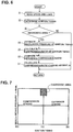
- Fig. 7 is the explanatory view illustrating a diagnostic area.
- the axis of abscissa is taken as "ignition timing”
- the axis of ordinate is taken as "intake pressure”.
- a diagnosis on a time-dependent change in compression ratio is carried out within a specified diagnostic area in which the intake pressure is high and ignition timing is set near the top dead center (TDC) position.
- the diagnostic area corresponds to approximately a low-speed full-load range of internal combustion engine 1.
- execution of the diagnosis is not limited to a steady operation.
- the diagnosis may be carried out under another operating condition in which ignition timing has controlled and retarded to the vicinity of the TDC position (i.e., within the diagnostic area) due to a certain factor.
- Fig. 8 is the explanatory view illustrating the relationship between them. For instance, suppose that, at the initial phase of an operating condition in which an in-cylinder pressure at ignition timing is comparatively high, the in-cylinder pressure is a pressure value denoted by a point "P1", and then a given time-dependent change in mechanical compression ratio occurs. As a result of this, the in-cylinder pressure shifts to a pressure value denoted by a point "P2".
- step S3 determines that the current operating condition is within the diagnostic area
- the routine proceeds to step S4.
- step S4 an in-cylinder pressure Pign at ignition timing is estimated based on the current value Idis according to the characteristic of Fig. 5 . For instance, a corresponding value to be estimated is retrieved from a table created according to the characteristic of Fig. 5 .
- a compression ratio ⁇ ign (a mechanical compression ratio) at ignition timing is calculated based on the in-cylinder pressure Pign at ignition timing.
- In-cylinder pressure Pign at ignition timing has a specified relationship with an intake pressure P1, a compression ratio ⁇ ign at ignition timing, and a ratio of specific heat ⁇ , as defined by the following expression (1).
- Pign P 1 ⁇ ⁇ ign ⁇
- the compression ratio ⁇ ign at ignition timing is derived from the following expression (2).
- ⁇ ign exp ln Pign / P 1 / ⁇
- the intake pressure P1 and the ratio of specific heat ⁇ can be obtained by reference to a pre-prepared map or table created based on engine revolution speed and load, or ignition timing, which informational signals are taken as parameters.
- intake pressure P1 may be detected directly by means of an intake pressure sensor, which is installed in the intake collector 8.
- the estimated compression ratio ⁇ ign at ignition timing is compared to an original reference compression ratio (a reference mechanical compression ratio at the same ignition timing).
- the reference compression ratio is retrieved from the pre-prepared table created based on ignition timing taken as a parameter.
- a piston position may be determined or derived from ignition timing, and then a reference compression ratio corresponding to each ignition timing may be calculated based on the determined piston position.
- step S6 an amount of time-dependent change in compression ratio at ignition timing can be determined or derived from the comparison results.
- step S7 the amount of time-dependent change in compression ratio at ignition timing is finally converted into an amount of change ⁇ in mechanical compression ratio ⁇ at the piston top dead center (TDC) position, generally denoted as "mechanical compression ratio”.
- an amount of time-dependent change ⁇ in compression ratio of a certain cylinder can be calculated.
- the time-dependent change in compression ratio of each of cylinders can be calculated.
- an in-cylinder pressure at ignition timing is estimated based on both an engine revolution speed and a discharge duration during which a secondary current flows. That is, as shown in Fig. 4B , engine controller 10 reads a time duration, during which a secondary current above a predetermined threshold value flows, as a discharge duration Tdis.
- the previously-noted threshold value is set to an appropriate value suited to avoid erroneous detection. For instance, the threshold value may be set to a predetermined minimum value substantially equivalent to a zero current value.
- the detected discharge duration Tdis which is explained by reference to Fig. 4B , is correlated with an in-cylinder pressure at ignition timing (i.e., a gas pressure between the electrodes).
- the correlation between them has a characteristic such that the discharge duration shortens as the in-cylinder pressure increases, for example, a linear correlation.
- the discharge duration shortens, as the engine revolution speed increases. Except for a change in engine revolution speed, the correlation between them is hardly affected irrespective of a change in the intensity of gas flow. Therefore, it is possible to univocally estimate the in-cylinder pressure at ignition timing based on both the discharge duration Tdis and engine revolution speed.
- FIG. 10 there is shown the flowchart illustrating the flow of concrete processing of the second embodiment in which in-cylinder pressure estimation is utilized for estimation of a time-dependent change in mechanical compression ratio.
- the processing shown in this flowchart is executed within the engine controller 10 each time each cylinder is ignited.
- step S1 engine revolution speed and load of internal combustion engine 1 are read, and then at step S2 ignition timing is determined.
- step S3 a check is made to determine whether an operating condition suited to carry out a diagnosis on a time-dependent change in mechanical compression ratio is satisfied.
- the routine proceeds to step S4A.
- an in-cylinder pressure Pign at ignition timing is estimated based on the discharge duration Tdis and engine revolution speed according to the characteristic of Fig. 9 . For instance, a corresponding value to be estimated is retrieved from a three-dimensional map created according to the characteristic of Fig. 9 .
- step S5 a compression ratio ⁇ ign at ignition timing is calculated based on the in-cylinder pressure Pign at ignition timing.
- the estimated compression ratio ⁇ ign at ignition timing is compared to an original reference compression ratio (a reference mechanical compression ratio at the same ignition timing).
- step S7 an amount of change ⁇ in mechanical compression ratio ⁇ at the piston TDC position is calculated.
- an amount of time-dependent change ⁇ in compression ratio of a certain cylinder can be calculated.
- the time-dependent change in compression ratio of each of cylinders can be calculated.
- FIG. 11 there is shown the flowchart illustrating one example of processing executed responsively to the time-dependent change in compression ratio obtained by the system of the first embodiment or the second embodiment.
- the example of Fig. 11 shows the processing in which when a time-dependent change in mechanical compression ratio (concretely, an increase in mechanical compression ratio) has occurred due to accumulation of deposits, an effective compression ratio is reduced to less than a normal set value via the variable valve actuation device 6 in order to suppress pre-ignition or knocking.
- an amount of time-dependent change ⁇ in mechanical compression ratio (simply, an amount of time-dependent change in compression ratio) is calculated.
- a check is made to determine whether the amount of time-dependent change ⁇ in compression ratio is greater than a threshold value ⁇ .
- the routine proceeds to step S13 where it determines whether or not the current operating condition is within a predetermined low-speed high-load range in which abnormal combustion, such as pre-ignition or knocking, tends to occur.
- step S13 When the answer to this step S13 is in the affirmative (YES), the routine proceeds to step S14 where intake valve closure timing (IVC) timed after the bottom dead center (BDC) position is retarded and corrected via the variable valve actuation device 6, with the result that the effective compression ratio is reduced to less than a normal set value.
- step S12 intake valve closure timing
- step S13 when the answer to step S13 is in the negative (NO) or when the answer to step S13 is in the negative (NO), the routine proceeds to step S15 where intake valve closure timing is controlled as usual.
- variable valve actuation device 6 is configured to individually vary intake valve closure timings for each individual cylinder
- intake valve closure timings can be individually retarded and corrected for each individual cylinder responsively to the compression-ratio change amount ⁇ of each of the cylinders.
- a mean value of compression-ratio change amounts ⁇ of all of cylinders or a maximum value of compression-ratio change amounts ⁇ of the individual cylinders may be compared to a permissible value (i.e., threshold value ⁇ ) at step S12 for instance.
- FIG. 12 there is shown the flowchart illustrating another example of processing executed responsively to the time-dependent change in compression ratio obtained by the system of the first embodiment or the second embodiment.
- the example of Fig. 12 shows the processing in which when a time-dependent change in mechanical compression ratio (concretely, an increase in mechanical compression ratio) has occurred due to accumulation of deposits, a fuel injection amount of an associated cylinder is increased in order to suppress pre-ignition or knocking.
- step S11 according to the previously-discussed processing method of the first embodiment or the second embodiment, an amount of time-dependent change ⁇ in mechanical compression ratio is calculated.
- step S12 a check is made to determine whether the amount of time-dependent change ⁇ in compression ratio is greater than a threshold value ⁇ (that is, a permissible value).
- step S13 determines whether or not the current operating condition is within a predetermined low-speed high-load range in which abnormal combustion, such as pre-ignition or knocking, tends to occur.
- step S14A a fuel injection amount injected from the fuel injection valve 2 is incrementally corrected.
- step S15A the fuel injection amount is controlled as usual.
- the previously-discussed incremental correction to a fuel injection amount for the purpose of suppressing knocking and the like may be made to only the cylinder whose compression-ratio change amount ⁇ exceeds the threshold value ⁇ .
- the previously-discussed incremental correction to a fuel injection amount for the purpose of suppressing knocking and the like may be made to all of cylinders simultaneously.
- deposit combustion operation may be executed to positively raise the combustion temperature.
- detection (estimation) of in-cylinder pressure at ignition timing is utilized for or applied to detection (estimation) of a time-dependent change in mechanical compression ratio. Furthermore, it is possible to detect a variation (a dispersion) in compression ratio between cylinders in a multi-cylinder internal combustion engine, utilizing detection of in-cylinder pressure at ignition timing. That is, it is possible to easily detect a variation (a dispersion) in compression ratio between cylinders by individually detecting an in-cylinder pressure at ignition timing of each individual cylinder during operation of the internal combustion engine. Thus, a correction to a fuel injection amount and fuel injection timing for each of the cylinders and a correction to ignition timing for each of the cylinders can be made, while taking account of the previously-noted dispersion in compression ratio.
Landscapes
- Engineering & Computer Science (AREA)
- Chemical & Material Sciences (AREA)
- Combustion & Propulsion (AREA)
- Mechanical Engineering (AREA)
- General Engineering & Computer Science (AREA)
- Combined Controls Of Internal Combustion Engines (AREA)
- Ignition Installations For Internal Combustion Engines (AREA)
- Electrical Control Of Ignition Timing (AREA)
Applications Claiming Priority (1)
| Application Number | Priority Date | Filing Date | Title |
|---|---|---|---|
| PCT/JP2014/053601 WO2015122004A1 (ja) | 2014-02-17 | 2014-02-17 | 内燃機関の点火装置および点火方法 |
Publications (3)
| Publication Number | Publication Date |
|---|---|
| EP3109457A1 true EP3109457A1 (de) | 2016-12-28 |
| EP3109457A4 EP3109457A4 (de) | 2017-03-15 |
| EP3109457B1 EP3109457B1 (de) | 2018-06-20 |
Family
ID=53799767
Family Applications (1)
| Application Number | Title | Priority Date | Filing Date |
|---|---|---|---|
| EP14882294.3A Not-in-force EP3109457B1 (de) | 2014-02-17 | 2014-02-17 | Zündvorrichtung und zündverfahren für einen verbrennungsmotor |
Country Status (5)
| Country | Link |
|---|---|
| US (1) | US10519879B2 (de) |
| EP (1) | EP3109457B1 (de) |
| JP (1) | JP6090481B2 (de) |
| CN (1) | CN106030099B (de) |
| WO (1) | WO2015122004A1 (de) |
Families Citing this family (4)
| Publication number | Priority date | Publication date | Assignee | Title |
|---|---|---|---|---|
| JP6302822B2 (ja) * | 2014-11-13 | 2018-03-28 | 日立オートモティブシステムズ株式会社 | 内燃機関の制御装置 |
| JP6796989B2 (ja) * | 2016-10-18 | 2020-12-09 | 株式会社エッチ・ケー・エス | 内燃機関用点火装置 |
| JP7101460B2 (ja) * | 2017-05-10 | 2022-07-15 | 日立Astemo株式会社 | 内燃機関の制御装置 |
| JP7324384B2 (ja) * | 2021-02-24 | 2023-08-09 | 日立Astemo株式会社 | 筒内圧力検出方法、筒内圧センサ診断方法及び内燃機関制御装置 |
Family Cites Families (17)
| Publication number | Priority date | Publication date | Assignee | Title |
|---|---|---|---|---|
| JPS6236116Y2 (de) * | 1981-05-19 | 1987-09-14 | ||
| DE3234629A1 (de) * | 1982-09-18 | 1984-03-22 | Robert Bosch Gmbh, 7000 Stuttgart | Einrichtung zum erfassen von druckschwankungen im brennraum einer brennkraftmaschine |
| JP2592075B2 (ja) * | 1987-10-19 | 1997-03-19 | 日産自動車株式会社 | 可変圧縮比型内燃機関の制御装置 |
| US4836015A (en) * | 1988-06-14 | 1989-06-06 | General Motors Corporation | Method and apparatus for determining the compression ratio of an engine cylinder |
| JP2705041B2 (ja) | 1991-03-12 | 1998-01-26 | 本田技研工業株式会社 | 内燃機関の失火検出装置 |
| US5408870A (en) * | 1993-11-08 | 1995-04-25 | Chrysler Corporation | Method for detecting the load on an internal combustion engine |
| JPH10196507A (ja) * | 1997-01-09 | 1998-07-31 | Nippon Soken Inc | 燃焼状態検出装置 |
| JP2000034969A (ja) * | 1998-07-15 | 2000-02-02 | Ngk Spark Plug Co Ltd | スパークプラグを用いた燃焼状態検出装置 |
| JP2001020805A (ja) * | 1999-07-06 | 2001-01-23 | Honda Motor Co Ltd | 内燃機関制御装置 |
| DE10201164A1 (de) * | 2002-01-15 | 2003-08-14 | Bosch Gmbh Robert | Verfahren und Vorrichtung zur Erkennung einer Phase eines Viertakt-Ottomotors |
| JP2005048621A (ja) * | 2003-07-31 | 2005-02-24 | Toyota Motor Corp | 内燃機関の圧縮比算出装置、圧縮比算出方法、内燃機関の制御装置およびその制御方法 |
| JP4397804B2 (ja) * | 2004-12-27 | 2010-01-13 | 本田技研工業株式会社 | ノッキング検出装置 |
| JP2011220309A (ja) * | 2010-04-14 | 2011-11-04 | Toyota Motor Corp | 点火プラグの磨耗量推定装置、内燃機関の制御装置 |
| JP5392241B2 (ja) | 2010-12-03 | 2014-01-22 | 三菱自動車工業株式会社 | 多気筒内燃機関 |
| JP5983740B2 (ja) * | 2012-05-14 | 2016-09-06 | トヨタ自動車株式会社 | 内燃機関の制御装置 |
| WO2016063430A1 (ja) * | 2014-10-24 | 2016-04-28 | 日立オートモティブシステムズ阪神株式会社 | 内燃機関用失火検出方法 |
| JP6302822B2 (ja) * | 2014-11-13 | 2018-03-28 | 日立オートモティブシステムズ株式会社 | 内燃機関の制御装置 |
-
2014
- 2014-02-17 JP JP2015562669A patent/JP6090481B2/ja not_active Expired - Fee Related
- 2014-02-17 CN CN201480075764.5A patent/CN106030099B/zh not_active Expired - Fee Related
- 2014-02-17 WO PCT/JP2014/053601 patent/WO2015122004A1/ja not_active Ceased
- 2014-02-17 EP EP14882294.3A patent/EP3109457B1/de not_active Not-in-force
- 2014-02-17 US US15/116,667 patent/US10519879B2/en not_active Expired - Fee Related
Also Published As
| Publication number | Publication date |
|---|---|
| EP3109457B1 (de) | 2018-06-20 |
| WO2015122004A1 (ja) | 2015-08-20 |
| CN106030099B (zh) | 2018-12-04 |
| JPWO2015122004A1 (ja) | 2017-03-30 |
| US20160348596A1 (en) | 2016-12-01 |
| CN106030099A (zh) | 2016-10-12 |
| EP3109457A4 (de) | 2017-03-15 |
| JP6090481B2 (ja) | 2017-03-08 |
| US10519879B2 (en) | 2019-12-31 |
Similar Documents
| Publication | Publication Date | Title |
|---|---|---|
| US6786200B2 (en) | Method and apparatus for controlling combustion quality in lean burn reciprocating engines | |
| EP3004604B1 (de) | Fehlzündungsdetektor für einen verbrennungsmotor | |
| US9068522B2 (en) | Method for diagnosing an engine | |
| US10900461B2 (en) | System and method for monitoring an ignition system | |
| US20150128683A1 (en) | Engine control device | |
| RU2682176C2 (ru) | Способ (варианты) и система контроля преждевременного зажигания | |
| US20150159569A1 (en) | Method and apparatus for detecting combustion phase of engine by angular acceleration signal and combustion data of single cylinder | |
| CN113825900B (zh) | 内燃机用控制装置 | |
| EP3109457B1 (de) | Zündvorrichtung und zündverfahren für einen verbrennungsmotor | |
| US8924134B2 (en) | Knock control device of internal combustion engine | |
| JP7106993B2 (ja) | 内燃機関の制御装置および内燃機関の制御方法 | |
| CN105593502B (zh) | 内燃机的控制装置 | |
| US20130192343A1 (en) | Knock detection device of internal combustion engine | |
| US10066594B2 (en) | Internal combustion engine having a spark plug | |
| US20100031923A1 (en) | Method and Apparatus for Detecting Engine Knock | |
| JP2012219757A (ja) | 内燃機関の制御装置 | |
| EP2918821A1 (de) | Motorsteuerungssystem | |
| CN107002579A (zh) | 用于检测火花点火内燃机中的自动点火的方法和装置 | |
| JP2011012608A (ja) | 内燃機関の異常着火制御装置 | |
| JP2013147946A (ja) | 内燃機関の制御装置 | |
| JP3860994B2 (ja) | 内燃機関の失火検出装置 | |
| JP4911135B2 (ja) | 自着火燃焼検出装置 | |
| JP2005233111A (ja) | 内燃機関の点火時期制御装置 | |
| JP2026018227A (ja) | 火花点火式内燃機関の放電制御装置及び火花点火式内燃機関の放電制御方法 | |
| JP2016056684A (ja) | エンジン制御装置 |
Legal Events
| Date | Code | Title | Description |
|---|---|---|---|
| PUAI | Public reference made under article 153(3) epc to a published international application that has entered the european phase |
Free format text: ORIGINAL CODE: 0009012 |
|
| STAA | Information on the status of an ep patent application or granted ep patent |
Free format text: STATUS: REQUEST FOR EXAMINATION WAS MADE |
|
| 17P | Request for examination filed |
Effective date: 20160902 |
|
| AK | Designated contracting states |
Kind code of ref document: A1 Designated state(s): AL AT BE BG CH CY CZ DE DK EE ES FI FR GB GR HR HU IE IS IT LI LT LU LV MC MK MT NL NO PL PT RO RS SE SI SK SM TR |
|
| AX | Request for extension of the european patent |
Extension state: BA ME |
|
| A4 | Supplementary search report drawn up and despatched |
Effective date: 20170213 |
|
| RIC1 | Information provided on ipc code assigned before grant |
Ipc: F02P 3/04 20060101ALN20170207BHEP Ipc: F02P 17/12 20060101ALI20170207BHEP Ipc: F02P 17/00 20060101AFI20170207BHEP Ipc: F02D 41/22 20060101ALN20170207BHEP Ipc: F02D 35/02 20060101ALN20170207BHEP |
|
| DAX | Request for extension of the european patent (deleted) | ||
| RIC1 | Information provided on ipc code assigned before grant |
Ipc: F02P 3/04 20060101ALN20171201BHEP Ipc: F02D 35/02 20060101ALN20171201BHEP Ipc: F02P 17/00 20060101AFI20171201BHEP Ipc: F02P 17/12 20060101ALI20171201BHEP Ipc: F02D 41/22 20060101ALN20171201BHEP |
|
| GRAP | Despatch of communication of intention to grant a patent |
Free format text: ORIGINAL CODE: EPIDOSNIGR1 |
|
| STAA | Information on the status of an ep patent application or granted ep patent |
Free format text: STATUS: GRANT OF PATENT IS INTENDED |
|
| INTG | Intention to grant announced |
Effective date: 20180205 |
|
| GRAS | Grant fee paid |
Free format text: ORIGINAL CODE: EPIDOSNIGR3 |
|
| GRAA | (expected) grant |
Free format text: ORIGINAL CODE: 0009210 |
|
| STAA | Information on the status of an ep patent application or granted ep patent |
Free format text: STATUS: THE PATENT HAS BEEN GRANTED |
|
| AK | Designated contracting states |
Kind code of ref document: B1 Designated state(s): AL AT BE BG CH CY CZ DE DK EE ES FI FR GB GR HR HU IE IS IT LI LT LU LV MC MK MT NL NO PL PT RO RS SE SI SK SM TR |
|
| REG | Reference to a national code |
Ref country code: GB Ref legal event code: FG4D |
|
| REG | Reference to a national code |
Ref country code: IE Ref legal event code: FG4D |
|
| REG | Reference to a national code |
Ref country code: AT Ref legal event code: REF Ref document number: 1010778 Country of ref document: AT Kind code of ref document: T Effective date: 20180715 |
|
| REG | Reference to a national code |
Ref country code: DE Ref legal event code: R096 Ref document number: 602014027416 Country of ref document: DE |
|
| REG | Reference to a national code |
Ref country code: NL Ref legal event code: MP Effective date: 20180620 |
|
| PG25 | Lapsed in a contracting state [announced via postgrant information from national office to epo] |
Ref country code: FI Free format text: LAPSE BECAUSE OF FAILURE TO SUBMIT A TRANSLATION OF THE DESCRIPTION OR TO PAY THE FEE WITHIN THE PRESCRIBED TIME-LIMIT Effective date: 20180620 Ref country code: BG Free format text: LAPSE BECAUSE OF FAILURE TO SUBMIT A TRANSLATION OF THE DESCRIPTION OR TO PAY THE FEE WITHIN THE PRESCRIBED TIME-LIMIT Effective date: 20180920 Ref country code: NO Free format text: LAPSE BECAUSE OF FAILURE TO SUBMIT A TRANSLATION OF THE DESCRIPTION OR TO PAY THE FEE WITHIN THE PRESCRIBED TIME-LIMIT Effective date: 20180920 Ref country code: LT Free format text: LAPSE BECAUSE OF FAILURE TO SUBMIT A TRANSLATION OF THE DESCRIPTION OR TO PAY THE FEE WITHIN THE PRESCRIBED TIME-LIMIT Effective date: 20180620 Ref country code: SE Free format text: LAPSE BECAUSE OF FAILURE TO SUBMIT A TRANSLATION OF THE DESCRIPTION OR TO PAY THE FEE WITHIN THE PRESCRIBED TIME-LIMIT Effective date: 20180620 |
|
| REG | Reference to a national code |
Ref country code: LT Ref legal event code: MG4D |
|
| PG25 | Lapsed in a contracting state [announced via postgrant information from national office to epo] |
Ref country code: HR Free format text: LAPSE BECAUSE OF FAILURE TO SUBMIT A TRANSLATION OF THE DESCRIPTION OR TO PAY THE FEE WITHIN THE PRESCRIBED TIME-LIMIT Effective date: 20180620 Ref country code: GR Free format text: LAPSE BECAUSE OF FAILURE TO SUBMIT A TRANSLATION OF THE DESCRIPTION OR TO PAY THE FEE WITHIN THE PRESCRIBED TIME-LIMIT Effective date: 20180921 Ref country code: LV Free format text: LAPSE BECAUSE OF FAILURE TO SUBMIT A TRANSLATION OF THE DESCRIPTION OR TO PAY THE FEE WITHIN THE PRESCRIBED TIME-LIMIT Effective date: 20180620 Ref country code: RS Free format text: LAPSE BECAUSE OF FAILURE TO SUBMIT A TRANSLATION OF THE DESCRIPTION OR TO PAY THE FEE WITHIN THE PRESCRIBED TIME-LIMIT Effective date: 20180620 |
|
| REG | Reference to a national code |
Ref country code: AT Ref legal event code: MK05 Ref document number: 1010778 Country of ref document: AT Kind code of ref document: T Effective date: 20180620 |
|
| PG25 | Lapsed in a contracting state [announced via postgrant information from national office to epo] |
Ref country code: NL Free format text: LAPSE BECAUSE OF FAILURE TO SUBMIT A TRANSLATION OF THE DESCRIPTION OR TO PAY THE FEE WITHIN THE PRESCRIBED TIME-LIMIT Effective date: 20180620 |
|
| PG25 | Lapsed in a contracting state [announced via postgrant information from national office to epo] |
Ref country code: CZ Free format text: LAPSE BECAUSE OF FAILURE TO SUBMIT A TRANSLATION OF THE DESCRIPTION OR TO PAY THE FEE WITHIN THE PRESCRIBED TIME-LIMIT Effective date: 20180620 Ref country code: RO Free format text: LAPSE BECAUSE OF FAILURE TO SUBMIT A TRANSLATION OF THE DESCRIPTION OR TO PAY THE FEE WITHIN THE PRESCRIBED TIME-LIMIT Effective date: 20180620 Ref country code: SK Free format text: LAPSE BECAUSE OF FAILURE TO SUBMIT A TRANSLATION OF THE DESCRIPTION OR TO PAY THE FEE WITHIN THE PRESCRIBED TIME-LIMIT Effective date: 20180620 Ref country code: PL Free format text: LAPSE BECAUSE OF FAILURE TO SUBMIT A TRANSLATION OF THE DESCRIPTION OR TO PAY THE FEE WITHIN THE PRESCRIBED TIME-LIMIT Effective date: 20180620 Ref country code: IS Free format text: LAPSE BECAUSE OF FAILURE TO SUBMIT A TRANSLATION OF THE DESCRIPTION OR TO PAY THE FEE WITHIN THE PRESCRIBED TIME-LIMIT Effective date: 20181020 Ref country code: EE Free format text: LAPSE BECAUSE OF FAILURE TO SUBMIT A TRANSLATION OF THE DESCRIPTION OR TO PAY THE FEE WITHIN THE PRESCRIBED TIME-LIMIT Effective date: 20180620 Ref country code: AT Free format text: LAPSE BECAUSE OF FAILURE TO SUBMIT A TRANSLATION OF THE DESCRIPTION OR TO PAY THE FEE WITHIN THE PRESCRIBED TIME-LIMIT Effective date: 20180620 |
|
| PG25 | Lapsed in a contracting state [announced via postgrant information from national office to epo] |
Ref country code: IT Free format text: LAPSE BECAUSE OF FAILURE TO SUBMIT A TRANSLATION OF THE DESCRIPTION OR TO PAY THE FEE WITHIN THE PRESCRIBED TIME-LIMIT Effective date: 20180620 Ref country code: ES Free format text: LAPSE BECAUSE OF FAILURE TO SUBMIT A TRANSLATION OF THE DESCRIPTION OR TO PAY THE FEE WITHIN THE PRESCRIBED TIME-LIMIT Effective date: 20180620 Ref country code: SM Free format text: LAPSE BECAUSE OF FAILURE TO SUBMIT A TRANSLATION OF THE DESCRIPTION OR TO PAY THE FEE WITHIN THE PRESCRIBED TIME-LIMIT Effective date: 20180620 |
|
| REG | Reference to a national code |
Ref country code: DE Ref legal event code: R097 Ref document number: 602014027416 Country of ref document: DE |
|
| PLBE | No opposition filed within time limit |
Free format text: ORIGINAL CODE: 0009261 |
|
| STAA | Information on the status of an ep patent application or granted ep patent |
Free format text: STATUS: NO OPPOSITION FILED WITHIN TIME LIMIT |
|
| 26N | No opposition filed |
Effective date: 20190321 |
|
| PG25 | Lapsed in a contracting state [announced via postgrant information from national office to epo] |
Ref country code: DK Free format text: LAPSE BECAUSE OF FAILURE TO SUBMIT A TRANSLATION OF THE DESCRIPTION OR TO PAY THE FEE WITHIN THE PRESCRIBED TIME-LIMIT Effective date: 20180620 |
|
| PG25 | Lapsed in a contracting state [announced via postgrant information from national office to epo] |
Ref country code: SI Free format text: LAPSE BECAUSE OF FAILURE TO SUBMIT A TRANSLATION OF THE DESCRIPTION OR TO PAY THE FEE WITHIN THE PRESCRIBED TIME-LIMIT Effective date: 20180620 |
|
| REG | Reference to a national code |
Ref country code: CH Ref legal event code: PL |
|
| PG25 | Lapsed in a contracting state [announced via postgrant information from national office to epo] |
Ref country code: MC Free format text: LAPSE BECAUSE OF FAILURE TO SUBMIT A TRANSLATION OF THE DESCRIPTION OR TO PAY THE FEE WITHIN THE PRESCRIBED TIME-LIMIT Effective date: 20180620 Ref country code: LU Free format text: LAPSE BECAUSE OF NON-PAYMENT OF DUE FEES Effective date: 20190217 |
|
| REG | Reference to a national code |
Ref country code: BE Ref legal event code: MM Effective date: 20190228 |
|
| REG | Reference to a national code |
Ref country code: IE Ref legal event code: MM4A |
|
| PG25 | Lapsed in a contracting state [announced via postgrant information from national office to epo] |
Ref country code: AL Free format text: LAPSE BECAUSE OF FAILURE TO SUBMIT A TRANSLATION OF THE DESCRIPTION OR TO PAY THE FEE WITHIN THE PRESCRIBED TIME-LIMIT Effective date: 20180620 |
|
| PG25 | Lapsed in a contracting state [announced via postgrant information from national office to epo] |
Ref country code: CH Free format text: LAPSE BECAUSE OF NON-PAYMENT OF DUE FEES Effective date: 20190228 Ref country code: LI Free format text: LAPSE BECAUSE OF NON-PAYMENT OF DUE FEES Effective date: 20190228 |
|
| PG25 | Lapsed in a contracting state [announced via postgrant information from national office to epo] |
Ref country code: IE Free format text: LAPSE BECAUSE OF NON-PAYMENT OF DUE FEES Effective date: 20190217 |
|
| PG25 | Lapsed in a contracting state [announced via postgrant information from national office to epo] |
Ref country code: BE Free format text: LAPSE BECAUSE OF NON-PAYMENT OF DUE FEES Effective date: 20190228 |
|
| PG25 | Lapsed in a contracting state [announced via postgrant information from national office to epo] |
Ref country code: TR Free format text: LAPSE BECAUSE OF FAILURE TO SUBMIT A TRANSLATION OF THE DESCRIPTION OR TO PAY THE FEE WITHIN THE PRESCRIBED TIME-LIMIT Effective date: 20180620 |
|
| PGFP | Annual fee paid to national office [announced via postgrant information from national office to epo] |
Ref country code: DE Payment date: 20200204 Year of fee payment: 7 Ref country code: GB Payment date: 20200206 Year of fee payment: 7 |
|
| PG25 | Lapsed in a contracting state [announced via postgrant information from national office to epo] |
Ref country code: PT Free format text: LAPSE BECAUSE OF FAILURE TO SUBMIT A TRANSLATION OF THE DESCRIPTION OR TO PAY THE FEE WITHIN THE PRESCRIBED TIME-LIMIT Effective date: 20181022 Ref country code: MT Free format text: LAPSE BECAUSE OF NON-PAYMENT OF DUE FEES Effective date: 20190217 |
|
| PGFP | Annual fee paid to national office [announced via postgrant information from national office to epo] |
Ref country code: FR Payment date: 20200113 Year of fee payment: 7 |
|
| PG25 | Lapsed in a contracting state [announced via postgrant information from national office to epo] |
Ref country code: CY Free format text: LAPSE BECAUSE OF FAILURE TO SUBMIT A TRANSLATION OF THE DESCRIPTION OR TO PAY THE FEE WITHIN THE PRESCRIBED TIME-LIMIT Effective date: 20180620 |
|
| PG25 | Lapsed in a contracting state [announced via postgrant information from national office to epo] |
Ref country code: HU Free format text: LAPSE BECAUSE OF FAILURE TO SUBMIT A TRANSLATION OF THE DESCRIPTION OR TO PAY THE FEE WITHIN THE PRESCRIBED TIME-LIMIT; INVALID AB INITIO Effective date: 20140217 |
|
| REG | Reference to a national code |
Ref country code: DE Ref legal event code: R119 Ref document number: 602014027416 Country of ref document: DE |
|
| GBPC | Gb: european patent ceased through non-payment of renewal fee |
Effective date: 20210217 |
|
| PG25 | Lapsed in a contracting state [announced via postgrant information from national office to epo] |
Ref country code: FR Free format text: LAPSE BECAUSE OF NON-PAYMENT OF DUE FEES Effective date: 20210228 Ref country code: GB Free format text: LAPSE BECAUSE OF NON-PAYMENT OF DUE FEES Effective date: 20210217 Ref country code: DE Free format text: LAPSE BECAUSE OF NON-PAYMENT OF DUE FEES Effective date: 20210901 |
|
| PG25 | Lapsed in a contracting state [announced via postgrant information from national office to epo] |
Ref country code: MK Free format text: LAPSE BECAUSE OF FAILURE TO SUBMIT A TRANSLATION OF THE DESCRIPTION OR TO PAY THE FEE WITHIN THE PRESCRIBED TIME-LIMIT Effective date: 20180620 |