EP3109551A1 - Procédé de commande à l'aide d'un controle des vibrations - Google Patents
Procédé de commande à l'aide d'un controle des vibrations Download PDFInfo
- Publication number
- EP3109551A1 EP3109551A1 EP16176121.8A EP16176121A EP3109551A1 EP 3109551 A1 EP3109551 A1 EP 3109551A1 EP 16176121 A EP16176121 A EP 16176121A EP 3109551 A1 EP3109551 A1 EP 3109551A1
- Authority
- EP
- European Patent Office
- Prior art keywords
- combustor
- group
- new
- reference value
- combustor cans
- Prior art date
- Legal status (The legal status is an assumption and is not a legal conclusion. Google has not performed a legal analysis and makes no representation as to the accuracy of the status listed.)
- Granted
Links
Images




Classifications
-
- F—MECHANICAL ENGINEERING; LIGHTING; HEATING; WEAPONS; BLASTING
- F23—COMBUSTION APPARATUS; COMBUSTION PROCESSES
- F23N—REGULATING OR CONTROLLING COMBUSTION
- F23N1/00—Regulating fuel supply
- F23N1/02—Regulating fuel supply conjointly with air supply
-
- F—MECHANICAL ENGINEERING; LIGHTING; HEATING; WEAPONS; BLASTING
- F02—COMBUSTION ENGINES; HOT-GAS OR COMBUSTION-PRODUCT ENGINE PLANTS
- F02C—GAS-TURBINE PLANTS; AIR INTAKES FOR JET-PROPULSION PLANTS; CONTROLLING FUEL SUPPLY IN AIR-BREATHING JET-PROPULSION PLANTS
- F02C9/00—Controlling gas-turbine plants; Controlling fuel supply in air- breathing jet-propulsion plants
- F02C9/26—Control of fuel supply
- F02C9/28—Regulating systems responsive to plant or ambient parameters, e.g. temperature, pressure, rotor speed
-
- F—MECHANICAL ENGINEERING; LIGHTING; HEATING; WEAPONS; BLASTING
- F23—COMBUSTION APPARATUS; COMBUSTION PROCESSES
- F23N—REGULATING OR CONTROLLING COMBUSTION
- F23N5/00—Systems for controlling combustion
- F23N5/02—Systems for controlling combustion using devices responsive to thermal changes or to thermal expansion of a medium
-
- F—MECHANICAL ENGINEERING; LIGHTING; HEATING; WEAPONS; BLASTING
- F23—COMBUSTION APPARATUS; COMBUSTION PROCESSES
- F23N—REGULATING OR CONTROLLING COMBUSTION
- F23N5/00—Systems for controlling combustion
- F23N5/16—Systems for controlling combustion using noise-sensitive detectors
-
- F—MECHANICAL ENGINEERING; LIGHTING; HEATING; WEAPONS; BLASTING
- F23—COMBUSTION APPARATUS; COMBUSTION PROCESSES
- F23N—REGULATING OR CONTROLLING COMBUSTION
- F23N5/00—Systems for controlling combustion
- F23N5/24—Preventing development of abnormal or undesired conditions, i.e. safety arrangements
-
- F—MECHANICAL ENGINEERING; LIGHTING; HEATING; WEAPONS; BLASTING
- F23—COMBUSTION APPARATUS; COMBUSTION PROCESSES
- F23R—GENERATING COMBUSTION PRODUCTS OF HIGH PRESSURE OR HIGH VELOCITY, e.g. GAS-TURBINE COMBUSTION CHAMBERS
- F23R3/00—Continuous combustion chambers using liquid or gaseous fuel
-
- F—MECHANICAL ENGINEERING; LIGHTING; HEATING; WEAPONS; BLASTING
- F05—INDEXING SCHEMES RELATING TO ENGINES OR PUMPS IN VARIOUS SUBCLASSES OF CLASSES F01-F04
- F05D—INDEXING SCHEME FOR ASPECTS RELATING TO NON-POSITIVE-DISPLACEMENT MACHINES OR ENGINES, GAS-TURBINES OR JET-PROPULSION PLANTS
- F05D2260/00—Function
- F05D2260/96—Preventing, counteracting or reducing vibration or noise
- F05D2260/964—Preventing, counteracting or reducing vibration or noise counteracting thermoacoustic noise
-
- F—MECHANICAL ENGINEERING; LIGHTING; HEATING; WEAPONS; BLASTING
- F05—INDEXING SCHEMES RELATING TO ENGINES OR PUMPS IN VARIOUS SUBCLASSES OF CLASSES F01-F04
- F05D—INDEXING SCHEME FOR ASPECTS RELATING TO NON-POSITIVE-DISPLACEMENT MACHINES OR ENGINES, GAS-TURBINES OR JET-PROPULSION PLANTS
- F05D2270/00—Control
- F05D2270/01—Purpose of the control system
- F05D2270/14—Purpose of the control system to control thermoacoustic behaviour in the combustion chambers
-
- F—MECHANICAL ENGINEERING; LIGHTING; HEATING; WEAPONS; BLASTING
- F23—COMBUSTION APPARATUS; COMBUSTION PROCESSES
- F23N—REGULATING OR CONTROLLING COMBUSTION
- F23N2237/00—Controlling
- F23N2237/02—Controlling two or more burners
-
- F—MECHANICAL ENGINEERING; LIGHTING; HEATING; WEAPONS; BLASTING
- F23—COMBUSTION APPARATUS; COMBUSTION PROCESSES
- F23N—REGULATING OR CONTROLLING COMBUSTION
- F23N2241/00—Applications
- F23N2241/20—Gas turbines
-
- F—MECHANICAL ENGINEERING; LIGHTING; HEATING; WEAPONS; BLASTING
- F23—COMBUSTION APPARATUS; COMBUSTION PROCESSES
- F23R—GENERATING COMBUSTION PRODUCTS OF HIGH PRESSURE OR HIGH VELOCITY, e.g. GAS-TURBINE COMBUSTION CHAMBERS
- F23R2900/00—Special features of, or arrangements for continuous combustion chambers; Combustion processes therefor
- F23R2900/00013—Reducing thermo-acoustic vibrations by active means
Definitions
- the present disclosure relates to a gas turbine, and more particularly, to a method of controlling a gas turbine by regulating vibration of a combustor.
- a gas turbine power plant of the related art determines an air flow rate and a fuel flow rate to be fed to a combustor according to a predetermined data, on the basis of the output of the generator, atmosphere temperature, and so forth, and operates a gas turbine by finely regulating the flow rates to proper values through a test run.
- a control device for the gas turbine power plant of the related art has a problem of immediately responding to variations in composition of the fuel, thereby lowering the combustion stability or generating combustion vibration.
- combustion vibration If the combustion vibration is generated above a reference value from the combustor, it impedes the safety operation of the gas turbine, as well as leading in mechanical damage. Accordingly, it is important to monitor the combustion vibration generated in the combustor for the industrial gas turbine plant in real time.
- a method of controlling the combustion vibration according to the related art controls all the combustors at the same time (see Korea Patent No. 10-0275375 ).
- the above method is not efficient since the output of even the stable combustor is decreased.
- the present disclosure has been made in view of the above problems, and one object of the present disclosure is to provide a method of controlling a gas turbine by grouping combustors and effectively regulating combustion vibration, thereby reducing the combustion vibration and thus improving stability of the gas turbine.
- a method of controlling the gas turbine detects the vibration of the combustor, groups the combustor cans exceeding a referenced value, and regulates the output for each group.
- a method of controlling a combustor for an operating gas turbine may include the steps: detecting of a combustion vibration value with a first detector provided to a plurality of combustor cans; comparing the combustion vibration value detected by the respective detectors and a predetermined reference value; grouping at least one combustor can, of which the combustion vibration value exceeds the reference value, to a first group, and at least one combustor can, of which the combustion vibration value does not exceed the reference value, to a second group; and controlling the first group by regulating an output with a control valve provided to the plurality of combustor cans, thereby lowering the combustion vibration value.
- the second group in the output control step, may not be controlled, or may be controlled to raise the output.
- the output control step may be to control an air-fuel ratio with the control valve.
- the group may be revoked, and the gas turbine may be controlled by repeating the detection step, the comparison step, the grouping step, and the output control step.
- a method of controlling a combustor for an operating gas turbine including the steps: detecting of a combustion vibration value with a first detector provided to a plurality of combustor cans; detecting of a temperature value with a second detector provided to the plurality of combustor cans; comparing the combustion vibration value detected by the respective first detectors and a predetermined reference value; comparing the temperature value detected by the respective second detectors and a predetermined reference value; grouping at least one combustor can, of which the combustion vibration value and the temperature value exceed the reference value, to a first group, and at least one combustor can, of which the combustion vibration value and the temperature value do not exceed the reference value, to a second group; and controlling the first group by regulating an output with a control valve provided to the plurality of combustor cans, thereby lowering the combustion vibration value.
- the method may further include grouping at least one combustor can of the second group, of which the combustion vibration value exceeds the reference and the temperature value does not exceed the reference value, to a third group, wherein the output control step controls the third group by regulating the output, thereby lowering the combustion vibration value.
- the method may further include grouping at least one combustor can of the second group, of which the combustion vibration value does not exceed the reference and the temperature value exceeds the reference value, to a fourth group, wherein the output control step controls the fourth group by regulating the output, thereby lowering the temperature value.
- the present disclosure groups and controls only the combustors exceeding the allowable combustion vibration value, thereby effectively controlling the gas turbine, raising the output thereof, and improving the stability.
- FIGS.1A and 1B show a gas turbine combustor.
- FIG.1A shows a gas turbine combustor 1 having a burner 10, a liner 20 and a transition piece 30.
- FIG.1B shows the burner 10 having a plurality of combustor cans 11 coupled to an annular shape.
- the positions and number of gas turbine combustors may be different from each other according to manufacturers or purposes of the gas turbine combustors. Also, even in the case where the plurality of combustor cans 11 are coupled to each other to take the annular shape, the number of combustor cans 11 may be different from each other.
- the control method according to the present disclosure is not limited to the structure of the combustor 1 or a specific shape to which the combustor is coupled and is thus applicable to a general gas turbine having the combustor 1 wherein the plurality of combustor cans 11 is coupled to each other.
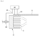
- FIG.2 shows any one of the plurality of combustor cans 11 of the burner 10.
- the combustor cans 11 may have the same structure as each other.
- Each combustor can 11 has a plurality of combustion nozzles 12 mounted therein, and fuel and compressed air whose flow rates are controlled by a control valve 300 are supplied to each combustion nozzle 12.
- the fuel injected from the combustion nozzles 12 is atomized by the compressed air and is then burnt in the internal space of the liner 20 constituting a combustion chamber.
- the present disclosure includes a first detector 100 that senses combustion vibrations, a second detector 200 that measures a temperature of each combustor can 11, and a controller 400 that processes and analyzes the signal values inputted from the first detector 100 and the second detector 200 through the operation and control functions thereof to control the operation of the control valve 300 according to the analyzed results.
- the control operation of the controller 400 will be explained in detail below.
- the controller 400 receives the signals from the first detector 100 and the second detector 200 disposed in each combustor can 11 and may individually control the control valve 300 disposed on each combustor can 11. That is, it is possible to conduct individual control for each combustor can 11, and accordingly, some of the combustor cans 11 are controllable in the form of a group according to the objects of the present disclosure. The control of the combustor cans as the group will be discussed below.
- the position, the number or the like of the combustion nozzles is different depending upon its application. Also, in the case where a plurality of combustors are arranged and coupled in an annular design, the number of combustors may be different from each other.
- the control method of the present disclosure is not limited to the structure of the combustor, or a specific coupling structure of the combustor, and thus can be applied to general gas turbine. Hereinafter, preferred embodiments will be described based on the premise.
- a method of controlling the output of the gas turbine including a plurality of combustors which are coupled in an annular shape is carried out on the whole combustors as a unit. Specifically, if combustion vibration or temperature is detected to be above a maximum allowable value in the combustor cans, only a specific combustor is not controlled, but the output of the whole combustor cans is controlled to be lowered. There is a problem in that since the output of the combustor cans which are normally operated within the maximum allowable value is lowered, the entire operation efficiency of the gas turbine is generally lowered.
- the present disclosure provides a method of controlling the gas turbine by grouping the combustors of which the combustion vibration or the temperature is above a reference value, thereby raising the output of the gas turbine and improving the combustion safety.
- each combustor is provided with a detector and a control valve.
- FIG. 3 is a block diagram illustrating a method of controlling combustors for a gas turbine according to an embodiment of the present disclosure.
- the control method mainly includes a detection step 210, a comparison step 220, a grouping step 230, and an output control step 240.
- the detection step 210 is to obtain a combustion vibration value by a plurality of first detectors provided to plurality of combustor cans.
- Each first detector may be separately installed to each of the respective combustor cans.
- the first detector can be positioned at any of a combustion nozzle, a liner, or a transition piece in order to detect the combustion vibration.
- a plurality of subsidiary detectors may be provided to one combustor can. In this instance, the first detector may calculate measured combustion vibration values of the corresponding combustor can as an average value of the subsidiary detectors, and can calculate a representative value according to specific criteria.
- the respective combustion vibration values is compared with a predetermined reference value (step 220).
- the predetermined reference value is a stable numerical range or an allowable range which can be applied to the gas turbine of interest. It is determined by comparing the combustion vibration value calculated by the first detector and the reference value whether the combustion vibration value is within a normal value or not.
- the predetermined reference value is a value variably set depending upon the performance and structure of the gas turbine, fuel characteristics, atmosphere temperature, pressure and so forth.
- a grouping standard is whether the combustion vibration of the combustor can exceeds the reference value or not.
- the combustor cans are divided into one group of which the combustion vibration exceeds the reference value, and another group of which the combustion vibration does not exceed the reference value. After the combustor cans are grouped, the combustor cans in corresponding groups are considered as one unit, and the group proceeds to the output control step 240 as a unit.
- each combustor can has a separate control valve, the group of combustor cans which exceed the reference value is controlled by lowering the output, thereby decreasing the vibration value. Meanwhile, the group of combustor cans which do not exceed the reference value does not have its control adjusted.
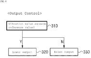
- FIG. 4 is a block diagram illustrating an example of the output control step. Referring to FIG. 4 , if the combustor cans which are set to any group exceeding the reference value (step 310), the group which exceeds the reference value is controlled to lower the output (step 320). The group which does not exceed the reference value is controlled to raise the output (step 330).
- the group of combustor cans which do not exceed the reference value means that it has a margin to raise the output by the reference value, the output thereof can be controlled to be raised. Therefore, the group exceeding the reference value is controlled to lower the output, thereby improving the stability of the gas turbine, and the group not exceeding the reference value is controlled to raise the output, thereby improving the efficiency of the gas turbine.
- the control method of lowering or raising the output is achieved by use of the control valve which is provided to the respective combustor cans.
- the output can be raised or lowered by regulating an air-fuel ratio fed to the combustor with each control valve. As the output is raised, the combustion vibration value and the temperature value are increased. As the output is lowered, the combustion vibration value and the temperature value are decreased.
- the output control has been described hereinbefore.
- the group may be reset/revoked and the disclosed combustor regulation method repeated.
- the detection step, comparison step, and the grouping step should be repeatedly carried out so as to continuously manage the gas turbine. This continuous repetition is important because a combustor group that had previously exceeded the reference value could have been adjusted so that its lowered output decreases the efficiency of the gas turbine, even though the combustor group is now within the stable range. Also, a combustor group that had its output increased could end up with a vibration value greater than the reference value. Accordingly, if a period of time has elapsed, each group should be reset/revoked, and then the detection step, the comparison step, and the regrouping step should repeatedly be carried out so as to continuously manage the gas turbine.
- FIG. 5 is a block diagram illustrating a method of controlling combustors for a gas turbine according to another embodiment of the present disclosure.
- the control method mainly includes detection steps 410 and 430, comparison steps 420 and 440, grouping steps 450, and an output control step 460.
- the first detection step 410 is to obtain a combustion vibration value by a plurality of first detectors provided to a plurality of combustor cans.
- Each first detector may be separately installed to each of the respective combustor cans.
- the first detector can be positioned at any of a combustion nozzle, a liner, or a transition piece in order to detect the combustion vibration.
- a plurality of first subsidiary detectors may be provided to one combustor can. In this instance, the first detector may calculate measured combustion vibration values of the corresponding combustor can as an average value of the first subsidiary detectors, and can calculate a representative value according to specific criteria.
- the second detection step 430 obtains a temperature value by a plurality of second detectors provided to the plurality of combustor cans.
- Each second detector may be separately installed to each of the respective combustor cans.
- the second detector can be positioned at any of the combustion nozzle, the liner, or the transition piece in order to detect the temperature.
- a plurality of second subsidiary detectors may be provided to one combustor can.
- the second detector may calculate measured temperature values of the corresponding combustor can as an average value of the second subsidiary detectors, and can calculate a representative value according to specific criteria.
- a single subsidiary detector may collect both combustion vibration and temperature, in lieu of having separate and distinct first and second subsidiary detectors.
- the respective combustion vibration values is compared with a predetermined reference value (step 420).
- the predetermined reference value is a stable numerical range or an allowable range which can be applied to the gas turbine of interest. By comparing the combustion vibration value calculated by the first detector and the reference value, it can be determined whether the combustion vibration value is within a normal value or not.
- the predetermined reference value is a value variably set depending upon the performance and structure of the gas turbine, fuel characteristics, atmosphere temperature, pressure and so forth.
- the respective combustion vibration values is compared with a predetermined temperature reference value (step 440).
- the predetermined temperature reference value is a stable numerical range or an allowable range which can be applied to the gas turbine of interest. By comparing the temperature value calculated by the second detector and the reference temperature value, it can be determined whether the temperature value is within a normal value or not.
- the predetermined temperature reference value is a value variably set depending upon the performance and structure of the gas turbine, fuel characteristics, atmosphere temperature, pressure and so forth.
- a grouping standard is whether the combustion vibration and the temperature of the combustor can respectively exceed the reference value or not, and the combustor cans are divided into one group exceeding both reference values, and the other group not exceeding both reference values. After the combustor cans are grouped, the combustor cans corresponding to the group are considered as one unit, and the group proceeds to the output control step 460 as a unit.
- each combustor can has a separate control valve, the group of combustor cans exceeding both reference values is controlled by lowering the output, thereby decreasing the vibration and temperature value. Meanwhile, the group of combustor cans not exceeding both reference values does not have its output lowered.(step 460)
- FIG. 6 is a block diagram illustrating the grouping step and the output control step.
- the group in the case of controlling the gas turbine by detecting the combustion vibration value and the temperature value, the group can be subdivided to control the output. It proceeds to a step 510 of determining whether the combustion vibration value exceeds the reference value (step 510), and the combustor cans are divided into one group exceeding the reference value and the other group not exceeding the reference value.
- a group of combustor cans, of which the combustion vibration value exceeds the reference value proceeds to a step 520 of determining whether the temperature value exceeds the temperature reference value. If the temperature value of this combustor can group exceed the temperature reference value, the group is set to a first group. Alternatively, if the temperature value of this combustor can group does not exceed the reference value, it is set to a third group.
- a group of combustor cans, of which the combustion vibration value does not exceed the reference value proceeds to a step 530 of determining whether the temperature value exceeds the temperature reference value (530). If the temperature value of this combustor can group exceed the temperature reference value, the group is set to a fourth group. Alternatively, if the temperature value of this combustor can group does not exceed the reference value, it is set to a second group.
- the combustor cans corresponding to the stable range, of which the combustion vibration value and the temperature value are less than the reference value, are set to the second group, and are controlled to raise the output.
- the combustor cans can be finely divided and grouped, relative to the case where the group is set only by use of the combustion vibration value. Therefore, the group can be controlled to operate the gas turbine in the more stable manner.
- the group may be reset.
- the gas turbine can be controlled by repeating the detection step, the comparison step, the grouping step, and the output control step. If the group is not again set, there is a problem in that even through the group exceeding the reference value is within the stable range, the output may still be lowered, thereby decreasing the efficiency of the gas turbine. Also, there is another problem in that the group not exceeding the reference value is not controlled, and then will exceed the reference value later. In addition, in the case of controlling the output to raise, the output will continuously be raised, so that the combustion vibration value will exceed the reference value.
- the preset group should be revoked, and then the detection step, the comparison step, and the regrouping step should repeatedly be carried out so as to continuously manage the gas turbine.
Landscapes
- Engineering & Computer Science (AREA)
- Chemical & Material Sciences (AREA)
- Combustion & Propulsion (AREA)
- Mechanical Engineering (AREA)
- General Engineering & Computer Science (AREA)
- Control Of Turbines (AREA)
Applications Claiming Priority (1)
| Application Number | Priority Date | Filing Date | Title |
|---|---|---|---|
| KR1020150090605A KR20170001104A (ko) | 2015-06-25 | 2015-06-25 | 진동제어를 통한 제어방법 |
Publications (2)
| Publication Number | Publication Date |
|---|---|
| EP3109551A1 true EP3109551A1 (fr) | 2016-12-28 |
| EP3109551B1 EP3109551B1 (fr) | 2019-03-27 |
Family
ID=56368801
Family Applications (1)
| Application Number | Title | Priority Date | Filing Date |
|---|---|---|---|
| EP16176121.8A Active EP3109551B1 (fr) | 2015-06-25 | 2016-06-24 | Procédé de commande à l'aide d'un contrôle des vibrations |
Country Status (4)
| Country | Link |
|---|---|
| US (1) | US10443842B2 (fr) |
| EP (1) | EP3109551B1 (fr) |
| KR (1) | KR20170001104A (fr) |
| WO (1) | WO2016208998A1 (fr) |
Families Citing this family (1)
| Publication number | Priority date | Publication date | Assignee | Title |
|---|---|---|---|---|
| FR3081925B1 (fr) * | 2018-05-29 | 2020-08-14 | Safran Aircraft Engines | Procede de surveillance des bougies d'allumage d'un turbomoteur exploitant une mesure vibratoire |
Citations (6)
| Publication number | Priority date | Publication date | Assignee | Title |
|---|---|---|---|---|
| JPH08246903A (ja) * | 1995-03-07 | 1996-09-24 | Hitachi Ltd | ガスタービン発電装置およびその制御方法 |
| KR100275375B1 (ko) | 1997-11-10 | 2000-12-15 | 이중구 | 가스터빈 제어 방법 |
| EP1286031A1 (fr) * | 2001-08-23 | 2003-02-26 | Mitsubishi Heavy Industries, Ltd. | Appareil de controle de turbine à gas |
| US7908072B2 (en) * | 2007-06-26 | 2011-03-15 | General Electric Company | Systems and methods for using a combustion dynamics tuning algorithm with a multi-can combustor |
| US20120196234A1 (en) * | 2009-10-09 | 2012-08-02 | Ghenadie Bulat | Combustion apparatus |
| US20140200721A1 (en) * | 2010-05-24 | 2014-07-17 | Hany Rizkalla | Stabilizing A Gas Turbine Engine Via Incremental Tuning During Transients |
Family Cites Families (19)
| Publication number | Priority date | Publication date | Assignee | Title |
|---|---|---|---|---|
| JPH09269107A (ja) * | 1996-03-29 | 1997-10-14 | Toshiba Corp | 燃焼器の燃焼振動抑制装置およびその抑制方法 |
| US7302334B2 (en) * | 2002-08-02 | 2007-11-27 | General Electric Company | Automatic mapping logic for a combustor in a gas turbine engine |
| DE102004015187A1 (de) * | 2004-03-29 | 2005-10-20 | Alstom Technology Ltd Baden | Brennkammer für eine Gasturbine und zugehöriges Betriebsverfahren |
| DE102004036911A1 (de) * | 2004-07-29 | 2006-03-23 | Alstom Technology Ltd | Betriebsverfahren für eine Feuerungsanlage |
| US20060032930A1 (en) * | 2004-08-13 | 2006-02-16 | Banner Engineering & Sales, Inc. | Methods and apparatus for controlling baking oven zone temperature |
| JP4592513B2 (ja) * | 2004-09-30 | 2010-12-01 | 三菱重工業株式会社 | ガスタービン制御装置、及びガスタービンシステム |
| US7461509B2 (en) * | 2005-05-06 | 2008-12-09 | General Electric Company | Method and system for determining lean blow out condition for gas turbine combustion cans |
| US7441411B2 (en) * | 2005-09-16 | 2008-10-28 | General Electric Company | Method and apparatus to detect onset of combustor hardware damage |
| US7503177B2 (en) * | 2006-03-17 | 2009-03-17 | Siemens Energy, Inc. | Combustion dynamics monitoring |
| US7654092B2 (en) * | 2006-07-18 | 2010-02-02 | Siemens Energy, Inc. | System for modulating fuel supply to individual fuel nozzles in a can-annular gas turbine |
| GB0715768D0 (en) * | 2007-08-14 | 2007-09-19 | Rolls Royce Plc | Sensor arrangement |
| JP5010502B2 (ja) * | 2008-02-28 | 2012-08-29 | 三菱重工業株式会社 | ガスタービン制御方法及び装置 |
| JP4995182B2 (ja) * | 2008-11-27 | 2012-08-08 | 三菱重工業株式会社 | ガスタービン制御方法及び装置 |
| JP5185791B2 (ja) * | 2008-11-28 | 2013-04-17 | 三菱重工業株式会社 | ガスタービン制御装置 |
| KR20140085691A (ko) * | 2012-12-27 | 2014-07-08 | 주식회사 포스코 | 가스 터빈의 자동 튜닝 장치 및 방법 |
| ITMI20130089A1 (it) * | 2013-01-23 | 2014-07-24 | Ansaldo Energia Spa | Impianto a turbina a gas per la produzione di energia elettrica e metodo per operare detto impianto |
| US9745896B2 (en) * | 2013-02-26 | 2017-08-29 | General Electric Company | Systems and methods to control combustion dynamic frequencies based on a compressor discharge temperature |
| US9423317B2 (en) * | 2013-12-31 | 2016-08-23 | Inventus Holdings, Llc | Combustion chamber measurement system |
| US9909508B2 (en) * | 2014-06-26 | 2018-03-06 | General Electric Company | Automatic combustion system characterization |
-
2015
- 2015-06-25 KR KR1020150090605A patent/KR20170001104A/ko not_active Ceased
-
2016
- 2016-06-23 WO PCT/KR2016/006695 patent/WO2016208998A1/fr not_active Ceased
- 2016-06-24 EP EP16176121.8A patent/EP3109551B1/fr active Active
- 2016-06-24 US US15/192,013 patent/US10443842B2/en active Active
Patent Citations (6)
| Publication number | Priority date | Publication date | Assignee | Title |
|---|---|---|---|---|
| JPH08246903A (ja) * | 1995-03-07 | 1996-09-24 | Hitachi Ltd | ガスタービン発電装置およびその制御方法 |
| KR100275375B1 (ko) | 1997-11-10 | 2000-12-15 | 이중구 | 가스터빈 제어 방법 |
| EP1286031A1 (fr) * | 2001-08-23 | 2003-02-26 | Mitsubishi Heavy Industries, Ltd. | Appareil de controle de turbine à gas |
| US7908072B2 (en) * | 2007-06-26 | 2011-03-15 | General Electric Company | Systems and methods for using a combustion dynamics tuning algorithm with a multi-can combustor |
| US20120196234A1 (en) * | 2009-10-09 | 2012-08-02 | Ghenadie Bulat | Combustion apparatus |
| US20140200721A1 (en) * | 2010-05-24 | 2014-07-17 | Hany Rizkalla | Stabilizing A Gas Turbine Engine Via Incremental Tuning During Transients |
Also Published As
| Publication number | Publication date |
|---|---|
| US10443842B2 (en) | 2019-10-15 |
| WO2016208998A1 (fr) | 2016-12-29 |
| US20160377285A1 (en) | 2016-12-29 |
| KR20170001104A (ko) | 2017-01-04 |
| EP3109551B1 (fr) | 2019-03-27 |
Similar Documents
| Publication | Publication Date | Title |
|---|---|---|
| CN100489290C (zh) | 降低燃气涡轮发动机工作期间燃烧室动压力的方法和装置 | |
| US10202906B2 (en) | Two-shaft gas turbine | |
| US10287993B2 (en) | Method and device for combustion with pulsed fuel split | |
| CA2190217C (fr) | Controle actif visant a reduire les emissions d'oxyde nitreux | |
| US7302334B2 (en) | Automatic mapping logic for a combustor in a gas turbine engine | |
| JP5550592B2 (ja) | ガスタービンの制御装置 | |
| RU2614471C2 (ru) | Способ и система регулирования для газовой турбины | |
| JP2006144796A (ja) | ガスタービン | |
| JP2008051099A (ja) | ガスタービン及びガスタービンを運転するためのびシステム | |
| JP2005509794A (ja) | ガスタービンエンジン制御装置における適応スケジュールのための方法と装置 | |
| US20100256888A1 (en) | Method and system for actively tuning a valve | |
| CN106968803A (zh) | 在燃气轮机调节中对功率输出‑排放参数的组合概率控制 | |
| CN106884724A (zh) | 对功率输出‑排放参数的燃气轮机调节中的概率控制建模 | |
| JP2017528633A (ja) | 自動式の燃焼システムの特徴付け | |
| CN104919159B (zh) | 燃气轮机系统、燃气轮机的燃烧器控制装置以及燃气轮机的燃烧器控制方法 | |
| US10443842B2 (en) | Control method using vibration control | |
| CN106884727A (zh) | 在燃气涡轮调节中对功率输出‑排放参数的概率控制 | |
| CN106988893A (zh) | 在燃气轮机调节中对功率输出‑排放参数的概率控制 | |
| EP2948660B1 (fr) | Centrale électrique à turbine à gaz pour la production d'énergie électrique et procédé d'actionnement de ladite centrale | |
| EP2249006B1 (fr) | Dispositif et procédé de réglage de la température de gaz d'échappement d'une turbine à gaz d'une centrale | |
| JP5818945B2 (ja) | ガスタービンの制御方法及びガスタービンの燃空比設定方法 | |
| KR101374356B1 (ko) | 항공기 공기흡입구의 왜곡 제어방법 | |
| JP2018178803A (ja) | ガスタービン制御装置、ガスタービン、及びガスタービン制御方法 | |
| JPH10227402A (ja) | 3位置制御式ボイラの台数制御装置 | |
| JPH11257650A (ja) | プラントのバーナ運転本数制御方法及びその制御装置 |
Legal Events
| Date | Code | Title | Description |
|---|---|---|---|
| PUAI | Public reference made under article 153(3) epc to a published international application that has entered the european phase |
Free format text: ORIGINAL CODE: 0009012 |
|
| STAA | Information on the status of an ep patent application or granted ep patent |
Free format text: STATUS: REQUEST FOR EXAMINATION WAS MADE |
|
| 17P | Request for examination filed |
Effective date: 20160713 |
|
| AK | Designated contracting states |
Kind code of ref document: A1 Designated state(s): AL AT BE BG CH CY CZ DE DK EE ES FI FR GB GR HR HU IE IS IT LI LT LU LV MC MK MT NL NO PL PT RO RS SE SI SK SM TR |
|
| AX | Request for extension of the european patent |
Extension state: BA ME |
|
| RBV | Designated contracting states (corrected) |
Designated state(s): AL AT BE BG CH CY CZ DE DK EE ES FI FR GB GR HR HU IE IS IT LI LT LU LV MC MK MT NL NO PL PT RO RS SE SI SK SM TR |
|
| GRAP | Despatch of communication of intention to grant a patent |
Free format text: ORIGINAL CODE: EPIDOSNIGR1 |
|
| STAA | Information on the status of an ep patent application or granted ep patent |
Free format text: STATUS: GRANT OF PATENT IS INTENDED |
|
| INTG | Intention to grant announced |
Effective date: 20181204 |
|
| GRAS | Grant fee paid |
Free format text: ORIGINAL CODE: EPIDOSNIGR3 |
|
| GRAA | (expected) grant |
Free format text: ORIGINAL CODE: 0009210 |
|
| STAA | Information on the status of an ep patent application or granted ep patent |
Free format text: STATUS: THE PATENT HAS BEEN GRANTED |
|
| AK | Designated contracting states |
Kind code of ref document: B1 Designated state(s): AL AT BE BG CH CY CZ DE DK EE ES FI FR GB GR HR HU IE IS IT LI LT LU LV MC MK MT NL NO PL PT RO RS SE SI SK SM TR |
|
| REG | Reference to a national code |
Ref country code: GB Ref legal event code: FG4D |
|
| REG | Reference to a national code |
Ref country code: CH Ref legal event code: EP |
|
| REG | Reference to a national code |
Ref country code: AT Ref legal event code: REF Ref document number: 1113541 Country of ref document: AT Kind code of ref document: T Effective date: 20190415 |
|
| REG | Reference to a national code |
Ref country code: IE Ref legal event code: FG4D |
|
| REG | Reference to a national code |
Ref country code: DE Ref legal event code: R096 Ref document number: 602016011465 Country of ref document: DE |
|
| PG25 | Lapsed in a contracting state [announced via postgrant information from national office to epo] |
Ref country code: LT Free format text: LAPSE BECAUSE OF FAILURE TO SUBMIT A TRANSLATION OF THE DESCRIPTION OR TO PAY THE FEE WITHIN THE PRESCRIBED TIME-LIMIT Effective date: 20190327 Ref country code: FI Free format text: LAPSE BECAUSE OF FAILURE TO SUBMIT A TRANSLATION OF THE DESCRIPTION OR TO PAY THE FEE WITHIN THE PRESCRIBED TIME-LIMIT Effective date: 20190327 Ref country code: NO Free format text: LAPSE BECAUSE OF FAILURE TO SUBMIT A TRANSLATION OF THE DESCRIPTION OR TO PAY THE FEE WITHIN THE PRESCRIBED TIME-LIMIT Effective date: 20190627 Ref country code: SE Free format text: LAPSE BECAUSE OF FAILURE TO SUBMIT A TRANSLATION OF THE DESCRIPTION OR TO PAY THE FEE WITHIN THE PRESCRIBED TIME-LIMIT Effective date: 20190327 |
|
| REG | Reference to a national code |
Ref country code: NL Ref legal event code: MP Effective date: 20190327 |
|
| PG25 | Lapsed in a contracting state [announced via postgrant information from national office to epo] |
Ref country code: NL Free format text: LAPSE BECAUSE OF FAILURE TO SUBMIT A TRANSLATION OF THE DESCRIPTION OR TO PAY THE FEE WITHIN THE PRESCRIBED TIME-LIMIT Effective date: 20190327 Ref country code: RS Free format text: LAPSE BECAUSE OF FAILURE TO SUBMIT A TRANSLATION OF THE DESCRIPTION OR TO PAY THE FEE WITHIN THE PRESCRIBED TIME-LIMIT Effective date: 20190327 Ref country code: GR Free format text: LAPSE BECAUSE OF FAILURE TO SUBMIT A TRANSLATION OF THE DESCRIPTION OR TO PAY THE FEE WITHIN THE PRESCRIBED TIME-LIMIT Effective date: 20190628 Ref country code: HR Free format text: LAPSE BECAUSE OF FAILURE TO SUBMIT A TRANSLATION OF THE DESCRIPTION OR TO PAY THE FEE WITHIN THE PRESCRIBED TIME-LIMIT Effective date: 20190327 Ref country code: LV Free format text: LAPSE BECAUSE OF FAILURE TO SUBMIT A TRANSLATION OF THE DESCRIPTION OR TO PAY THE FEE WITHIN THE PRESCRIBED TIME-LIMIT Effective date: 20190327 Ref country code: BG Free format text: LAPSE BECAUSE OF FAILURE TO SUBMIT A TRANSLATION OF THE DESCRIPTION OR TO PAY THE FEE WITHIN THE PRESCRIBED TIME-LIMIT Effective date: 20190627 |
|
| REG | Reference to a national code |
Ref country code: AT Ref legal event code: MK05 Ref document number: 1113541 Country of ref document: AT Kind code of ref document: T Effective date: 20190327 |
|
| PG25 | Lapsed in a contracting state [announced via postgrant information from national office to epo] |
Ref country code: AL Free format text: LAPSE BECAUSE OF FAILURE TO SUBMIT A TRANSLATION OF THE DESCRIPTION OR TO PAY THE FEE WITHIN THE PRESCRIBED TIME-LIMIT Effective date: 20190327 Ref country code: PT Free format text: LAPSE BECAUSE OF FAILURE TO SUBMIT A TRANSLATION OF THE DESCRIPTION OR TO PAY THE FEE WITHIN THE PRESCRIBED TIME-LIMIT Effective date: 20190727 Ref country code: ES Free format text: LAPSE BECAUSE OF FAILURE TO SUBMIT A TRANSLATION OF THE DESCRIPTION OR TO PAY THE FEE WITHIN THE PRESCRIBED TIME-LIMIT Effective date: 20190327 Ref country code: CZ Free format text: LAPSE BECAUSE OF FAILURE TO SUBMIT A TRANSLATION OF THE DESCRIPTION OR TO PAY THE FEE WITHIN THE PRESCRIBED TIME-LIMIT Effective date: 20190327 Ref country code: EE Free format text: LAPSE BECAUSE OF FAILURE TO SUBMIT A TRANSLATION OF THE DESCRIPTION OR TO PAY THE FEE WITHIN THE PRESCRIBED TIME-LIMIT Effective date: 20190327 Ref country code: IT Free format text: LAPSE BECAUSE OF FAILURE TO SUBMIT A TRANSLATION OF THE DESCRIPTION OR TO PAY THE FEE WITHIN THE PRESCRIBED TIME-LIMIT Effective date: 20190327 Ref country code: SK Free format text: LAPSE BECAUSE OF FAILURE TO SUBMIT A TRANSLATION OF THE DESCRIPTION OR TO PAY THE FEE WITHIN THE PRESCRIBED TIME-LIMIT Effective date: 20190327 Ref country code: RO Free format text: LAPSE BECAUSE OF FAILURE TO SUBMIT A TRANSLATION OF THE DESCRIPTION OR TO PAY THE FEE WITHIN THE PRESCRIBED TIME-LIMIT Effective date: 20190327 |
|
| PG25 | Lapsed in a contracting state [announced via postgrant information from national office to epo] |
Ref country code: PL Free format text: LAPSE BECAUSE OF FAILURE TO SUBMIT A TRANSLATION OF THE DESCRIPTION OR TO PAY THE FEE WITHIN THE PRESCRIBED TIME-LIMIT Effective date: 20190327 Ref country code: SM Free format text: LAPSE BECAUSE OF FAILURE TO SUBMIT A TRANSLATION OF THE DESCRIPTION OR TO PAY THE FEE WITHIN THE PRESCRIBED TIME-LIMIT Effective date: 20190327 |
|
| PG25 | Lapsed in a contracting state [announced via postgrant information from national office to epo] |
Ref country code: IS Free format text: LAPSE BECAUSE OF FAILURE TO SUBMIT A TRANSLATION OF THE DESCRIPTION OR TO PAY THE FEE WITHIN THE PRESCRIBED TIME-LIMIT Effective date: 20190727 Ref country code: AT Free format text: LAPSE BECAUSE OF FAILURE TO SUBMIT A TRANSLATION OF THE DESCRIPTION OR TO PAY THE FEE WITHIN THE PRESCRIBED TIME-LIMIT Effective date: 20190327 |
|
| REG | Reference to a national code |
Ref country code: DE Ref legal event code: R097 Ref document number: 602016011465 Country of ref document: DE |
|
| PG25 | Lapsed in a contracting state [announced via postgrant information from national office to epo] |
Ref country code: DK Free format text: LAPSE BECAUSE OF FAILURE TO SUBMIT A TRANSLATION OF THE DESCRIPTION OR TO PAY THE FEE WITHIN THE PRESCRIBED TIME-LIMIT Effective date: 20190327 Ref country code: MC Free format text: LAPSE BECAUSE OF FAILURE TO SUBMIT A TRANSLATION OF THE DESCRIPTION OR TO PAY THE FEE WITHIN THE PRESCRIBED TIME-LIMIT Effective date: 20190327 |
|
| REG | Reference to a national code |
Ref country code: CH Ref legal event code: PL |
|
| PLBE | No opposition filed within time limit |
Free format text: ORIGINAL CODE: 0009261 |
|
| STAA | Information on the status of an ep patent application or granted ep patent |
Free format text: STATUS: NO OPPOSITION FILED WITHIN TIME LIMIT |
|
| PG25 | Lapsed in a contracting state [announced via postgrant information from national office to epo] |
Ref country code: SI Free format text: LAPSE BECAUSE OF FAILURE TO SUBMIT A TRANSLATION OF THE DESCRIPTION OR TO PAY THE FEE WITHIN THE PRESCRIBED TIME-LIMIT Effective date: 20190327 |
|
| 26N | No opposition filed |
Effective date: 20200103 |
|
| REG | Reference to a national code |
Ref country code: BE Ref legal event code: MM Effective date: 20190630 |
|
| PG25 | Lapsed in a contracting state [announced via postgrant information from national office to epo] |
Ref country code: TR Free format text: LAPSE BECAUSE OF FAILURE TO SUBMIT A TRANSLATION OF THE DESCRIPTION OR TO PAY THE FEE WITHIN THE PRESCRIBED TIME-LIMIT Effective date: 20190327 |
|
| PG25 | Lapsed in a contracting state [announced via postgrant information from national office to epo] |
Ref country code: IE Free format text: LAPSE BECAUSE OF NON-PAYMENT OF DUE FEES Effective date: 20190624 |
|
| PG25 | Lapsed in a contracting state [announced via postgrant information from national office to epo] |
Ref country code: LU Free format text: LAPSE BECAUSE OF NON-PAYMENT OF DUE FEES Effective date: 20190624 Ref country code: LI Free format text: LAPSE BECAUSE OF NON-PAYMENT OF DUE FEES Effective date: 20190630 Ref country code: CH Free format text: LAPSE BECAUSE OF NON-PAYMENT OF DUE FEES Effective date: 20190630 Ref country code: BE Free format text: LAPSE BECAUSE OF NON-PAYMENT OF DUE FEES Effective date: 20190630 |
|
| PG25 | Lapsed in a contracting state [announced via postgrant information from national office to epo] |
Ref country code: FR Free format text: LAPSE BECAUSE OF NON-PAYMENT OF DUE FEES Effective date: 20190630 |
|
| GBPC | Gb: european patent ceased through non-payment of renewal fee |
Effective date: 20200624 |
|
| PG25 | Lapsed in a contracting state [announced via postgrant information from national office to epo] |
Ref country code: GB Free format text: LAPSE BECAUSE OF NON-PAYMENT OF DUE FEES Effective date: 20200624 |
|
| PG25 | Lapsed in a contracting state [announced via postgrant information from national office to epo] |
Ref country code: CY Free format text: LAPSE BECAUSE OF FAILURE TO SUBMIT A TRANSLATION OF THE DESCRIPTION OR TO PAY THE FEE WITHIN THE PRESCRIBED TIME-LIMIT Effective date: 20190327 |
|
| PG25 | Lapsed in a contracting state [announced via postgrant information from national office to epo] |
Ref country code: HU Free format text: LAPSE BECAUSE OF FAILURE TO SUBMIT A TRANSLATION OF THE DESCRIPTION OR TO PAY THE FEE WITHIN THE PRESCRIBED TIME-LIMIT; INVALID AB INITIO Effective date: 20160624 Ref country code: MT Free format text: LAPSE BECAUSE OF FAILURE TO SUBMIT A TRANSLATION OF THE DESCRIPTION OR TO PAY THE FEE WITHIN THE PRESCRIBED TIME-LIMIT Effective date: 20190327 |
|
| PG25 | Lapsed in a contracting state [announced via postgrant information from national office to epo] |
Ref country code: MK Free format text: LAPSE BECAUSE OF FAILURE TO SUBMIT A TRANSLATION OF THE DESCRIPTION OR TO PAY THE FEE WITHIN THE PRESCRIBED TIME-LIMIT Effective date: 20190327 |
|
| PGFP | Annual fee paid to national office [announced via postgrant information from national office to epo] |
Ref country code: DE Payment date: 20250402 Year of fee payment: 10 |