EP3109561A1 - Radiateur - Google Patents
Radiateur Download PDFInfo
- Publication number
- EP3109561A1 EP3109561A1 EP16174931.2A EP16174931A EP3109561A1 EP 3109561 A1 EP3109561 A1 EP 3109561A1 EP 16174931 A EP16174931 A EP 16174931A EP 3109561 A1 EP3109561 A1 EP 3109561A1
- Authority
- EP
- European Patent Office
- Prior art keywords
- connection
- flow
- return
- alternative
- radiator
- Prior art date
- Legal status (The legal status is an assumption and is not a legal conclusion. Google has not performed a legal analysis and makes no representation as to the accuracy of the status listed.)
- Granted
Links
Images


Classifications
-
- F—MECHANICAL ENGINEERING; LIGHTING; HEATING; WEAPONS; BLASTING
- F24—HEATING; RANGES; VENTILATING
- F24D—DOMESTIC- OR SPACE-HEATING SYSTEMS, e.g. CENTRAL HEATING SYSTEMS; DOMESTIC HOT-WATER SUPPLY SYSTEMS; ELEMENTS OR COMPONENTS THEREFOR
- F24D19/00—Details
- F24D19/0002—Means for connecting central heating radiators to circulation pipes
- F24D19/0009—In a two pipe system
- F24D19/0012—Comprising regulation means
-
- F—MECHANICAL ENGINEERING; LIGHTING; HEATING; WEAPONS; BLASTING
- F24—HEATING; RANGES; VENTILATING
- F24D—DOMESTIC- OR SPACE-HEATING SYSTEMS, e.g. CENTRAL HEATING SYSTEMS; DOMESTIC HOT-WATER SUPPLY SYSTEMS; ELEMENTS OR COMPONENTS THEREFOR
- F24D19/00—Details
- F24D19/0002—Means for connecting central heating radiators to circulation pipes
- F24D19/0017—Connections between supply and inlet or outlet of central heating radiators
- F24D19/0019—Means for adapting connections
-
- F—MECHANICAL ENGINEERING; LIGHTING; HEATING; WEAPONS; BLASTING
- F24—HEATING; RANGES; VENTILATING
- F24D—DOMESTIC- OR SPACE-HEATING SYSTEMS, e.g. CENTRAL HEATING SYSTEMS; DOMESTIC HOT-WATER SUPPLY SYSTEMS; ELEMENTS OR COMPONENTS THEREFOR
- F24D19/00—Details
- F24D19/0002—Means for connecting central heating radiators to circulation pipes
- F24D19/0017—Connections between supply and inlet or outlet of central heating radiators
- F24D19/0024—Connections for plate radiators
-
- F—MECHANICAL ENGINEERING; LIGHTING; HEATING; WEAPONS; BLASTING
- F24—HEATING; RANGES; VENTILATING
- F24D—DOMESTIC- OR SPACE-HEATING SYSTEMS, e.g. CENTRAL HEATING SYSTEMS; DOMESTIC HOT-WATER SUPPLY SYSTEMS; ELEMENTS OR COMPONENTS THEREFOR
- F24D19/00—Details
- F24D19/0002—Means for connecting central heating radiators to circulation pipes
- F24D19/0026—Places of the inlet on the radiator
- F24D19/0036—Places of the inlet on the radiator on the bottom in the middle
-
- F—MECHANICAL ENGINEERING; LIGHTING; HEATING; WEAPONS; BLASTING
- F24—HEATING; RANGES; VENTILATING
- F24D—DOMESTIC- OR SPACE-HEATING SYSTEMS, e.g. CENTRAL HEATING SYSTEMS; DOMESTIC HOT-WATER SUPPLY SYSTEMS; ELEMENTS OR COMPONENTS THEREFOR
- F24D19/00—Details
- F24D19/0002—Means for connecting central heating radiators to circulation pipes
- F24D19/0039—Places of the outlet on the radiator
- F24D19/0048—Places of the outlet on the radiator on the bottom in the middle
-
- F—MECHANICAL ENGINEERING; LIGHTING; HEATING; WEAPONS; BLASTING
- F24—HEATING; RANGES; VENTILATING
- F24D—DOMESTIC- OR SPACE-HEATING SYSTEMS, e.g. CENTRAL HEATING SYSTEMS; DOMESTIC HOT-WATER SUPPLY SYSTEMS; ELEMENTS OR COMPONENTS THEREFOR
- F24D19/00—Details
- F24D19/0002—Means for connecting central heating radiators to circulation pipes
- F24D19/0039—Places of the outlet on the radiator
- F24D19/0053—Places of the outlet on the radiator on the bottom on the same side
-
- F—MECHANICAL ENGINEERING; LIGHTING; HEATING; WEAPONS; BLASTING
- F24—HEATING; RANGES; VENTILATING
- F24D—DOMESTIC- OR SPACE-HEATING SYSTEMS, e.g. CENTRAL HEATING SYSTEMS; DOMESTIC HOT-WATER SUPPLY SYSTEMS; ELEMENTS OR COMPONENTS THEREFOR
- F24D19/00—Details
- F24D19/0002—Means for connecting central heating radiators to circulation pipes
- F24D19/0073—Means for changing the flow of the fluid inside a radiator
Definitions
- the present invention relates to a radiator according to the preamble of claim 1.
- Radiators with center connection and riser are basically known, for example from the DE 102 03 313 A1 or the DE 195 39 222 C1 ,
- the object of the present invention is to provide a center connection radiator of the type mentioned above with higher connection variability.
- the radiator according to the invention accordingly has a central inlet or. Flow connection garnish.
- Such center connections are now standard, especially in new buildings.
- at least one further off-center lateral alternative flow connection is now also provided, which, for example, is currently relevant for the replacement of radiators in old buildings.
- the flow characteristic of the radiator according to the invention in particular a multi-layer parallel-flow radiator, is fundamentally different than that of a serial radiator, in particular as that in the EP 2 428 748 A2 described radiator.
- the heating medium is - in the radiator according to the invention - regardless of which of the two flow connections, ie via the first flow connection or the second alternative flow connection - passed directly into the separate riser. Accordingly, this riser is not one of the heating channels of the heating plates but a defined tube which is the only connection for the heating fluid from the connection fitting to the above connectors. The heating medium can thus only and exclusively through this separate riser to the connectors and subsequently reach only in the hot plate or the heating plates.
- the second alternative flow connection is structurally connected via a pipe connection to the return housing, in particular laterally thereto, wherein the pipe connection passes through the return housing and is hydraulically connected to the riser.
- the second alternative flow connection is connected via a pipe connection structurally and hydraulically to the flow housing, in particular laterally.
- a pipe connection structurally and hydraulically to the flow housing, in particular laterally.
- the second alternative flow connection is connected via a pipe connection structurally and hydraulically directly to the riser, in particular to the lowermost portion of the riser immediately above the connection fitting.
- a third alternative flow connection and a third alternative return connection are provided, wherein the third flow connection to the connection fitting is also fluidly connected, so that flowing over the third flow connection heating fluid enters the distribution set.
- both left and right forward or return ports can be provided and the connection variety is further increased.
- the third alternative flow connection is connected constructively via a further pipe connection to that one free flow or return housing to which the second alternative flow connection is not connected.
- the positions at which the second alternative flow connection and the third alternative flow connection are structurally connected to the flow or return housing, in a common plane and on a common axis on opposite sides of the flow or return housing with respect to the longitudinal extent of the radiator.
- the second and possibly the third alternative flow connection and optionally the second and optionally the third alternative return connection are each arranged in one of the lateral, lower end regions of the radiator.
- the pipe connection has a releasable plug connection, via which the second, and each further, alternative flow connection and the second, and each further, alternative return connection are reversibly detachably connectable.
- the riser from the plane of the heating plate (s) or from the space with respect to the longitudinal extent of the heating plate (s) is centered, aligned straight and vertical.
- the second alternative flow connection and the second alternative return connection are constructively connected together to form a structural unit, in particular via a flat web. This also applies analogously to each additional flow and return connection.
- the second or third alternative return connection is designed as a return housing, in particular at least partially configured in the form of a spherical segment, and in each case has an end-face, laterally outwardly facing return connection connection piece. This allows additional connections for the return and the variability and connectivity is further increased.
- the radiator is designed as a multi-layer radiator with parallel flow and has at least two mutually parallel heating plates.
- the flow characteristic of such a multilayer parallel-flow radiator is fundamentally different than that of a serially flowed through radiator, in particular as that of the in the EP 2 428 748 A2 described radiator.
- the heating medium is - regardless of which of the two flow connections, ie via the first flow connection or the second alternative flow connection - passed directly into the separate riser in the inventive parallel flow heater and from there, as previously described distributed on all plates.
- a particularly advantageous embodiment provides that exactly two mutually parallel heating plates are provided, a first room-side heating plate and a second heating plate.
- the radiator is designed as a three-layer radiator with parallel flow and three or more parallel heating plates has, a first room-side heating plate, a second closer to the wall heating plate and at least one other room-side heating plate, the is located closer to the room or even more room side than the first room-side heating plate.
- first flow connection and the first return connection and preferably also the second and each further alternative flow connection and the second and each further alternative return connection are located between the first and the second heating plate.
- first flow connection and the first return connection are arranged in one plane eccentrically and unequally spaced from the first and second heating plate and / or if the second and each further alternative flow connection and the second and each further alternative return connection in a plane are arranged centrally and equally spaced from the first and second heating plate. This results in that the second, and everyone another alternative supply or return connection is not in the same plane between the heating plates, as the first supply and return connection. This is advantageous to obtain better compatibility, especially for old buildings.
- a lateral connection piece is provided as a further alternative return connection.
- connection flexibility if all lateral or frontal connections and connecting pieces of the radiator, in particular the connections of the connecting pieces, the return connection piece and / or the lateral connection piece, same dimensions, in particular the same inner diameter or thread dimensions, at least their internal thread exhibit.
- This advantageously serves for reciprocal, interchangeable insertion of valves and / or shut-off or sealing components.
- the side ports have advantageously a 1/2 inch internal thread, the downwardly facing flow and return ports a 3/4 inch external thread.
- serial flow is understood to mean that the heating medium is first distributed only in one of the heating plates, usually the room-side front panel, and only then enters the second, usually wall-side, heating plate or other heating plates via a valve or other connections ,
- parallel flow is understood in the present case that the coming from the flow of warm heating medium is guided substantially directly to the valve, usually via a riser, and is distributed from there into both heating plates. There, the heating medium decreases in each case and distributed over the collecting ducts and the heating channels in the two heating plates.
- hydrophilically or fluidically or fluidically or fluidly connected or connected is understood in the present case that two components or components are in communication with each other so that the heating medium can pass from one to the other component.
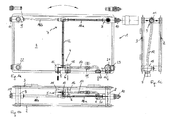
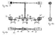
- a first possible embodiment of the radiator according to the invention is shown, namely a two-layer radiator 1 with parallel flow with two heating plates 2, 3, namely a front, in the room facing the first room-side heating plate 2 and another second, wall-side heating plate 3.
- the two heating plates 2, 3 are arranged parallel to each other and have in a known manner in each case an upper and a lower horizontal collecting channel with these connecting vertical heating channels.
- Konvektorbleche are usually arranged to increase the power through increased heat exchanger surface.
- these details are not shown in the schematic diagrams.
- connection fitting 4 designed as a center connection, comprising a first flow connection 5 and a second return connection 6 for the inlet and outlet of the heating medium.
- the connection fitting 4 is arranged in the region between the heating plates 2, 3, wherein the first flow connection 5 and the first return connection 6 are in a common plane parallel to the heating plates 2, 3, but off-center offset and not equal distance from the heating plates 2, 3 (eg Fig. 1b ).
- the first flow connection 5 and the first return connection 6 are formed in the present embodiment as a ball-segment-shaped flow or return housing 15, 16.
- a riser 12 is connected constructively.
- This riser 12 is hydraulically or fluidly or fluidically or fluidly connected exclusively to the flow connection 5.
- the riser 12 is located in the space between the heating plates 2, 3 and extends in relation to the longitudinal extent of the heating plates 2, 3 centrally and straight vertically upwards. As in Fig. 1c it can be seen, however, the riser 12 has a pivoting or a double bend and extends from the off-center lowermost position of the connection fitting 4 in a central position in the upper region and each of the heating plates 2, 3 equally spaced position.
- the riser 12 is a separate component or a separate tube, which is not part of the two heating plates 2, 3 and is connected directly to them neither mechanically nor fluidically. In particular, the riser 12 is not a vertical heating channel of a heating plate 2, 3.
- the riser pipe 12 is part of a distributor set 7, wherein the riser pipe 12 has a T-junction in the uppermost region and merges into a horizontal pipe 18a, 18b to the left and right.
- each designed as a connection connecting piece 8, 9 is connected.
- a shut-off or sealing member 11 for preventing the entry of heating fluid in the or the flow of heating fluid between the heating plates 2, 3 is used.
- a valve 10 for Regulation of the flow and for parallel distribution of the coming from the first flow connection 5 heating fluid in the heating plates 2, 3 used. In this way, the parallel flow through the radiator 1 is ensured accordingly.
- the riser 12 is thus the only fluid connection for the heating fluid from the connection fitting 4 to the two connecting pieces 8, 9th
- the radiator 1 is shown in frontal view, top view and side view, with black continuous and hatched arrows the flow characteristics of the heating medium are indicated.
- the flow paths marked by the black arrows are in principle the same in all other embodiments described here:
- the heating medium enters the flow housing 15 via the first flow connection 5 and reaches directly into the riser pipe 12. There, it rises and takes the path over the , here right, horizontal pipe 18a to the connector 8.
- the flow rate of the heating medium is controlled in the heating plates 2,3 and open valve 10 enters the heating medium, as in Fig. 1c visible, both in the left room-side heating plate 2 and in the right wall-side heating plate 3.
- the warm heating medium distributed according to the upper horizontal collecting ducts decreases over the vertical heating channels and distributed in this way on both heating plates 2.3 parallel. From the lower collecting channel of the wall-side heating plate 3, the heating medium passes through the central return housing 16 to the first return port 6 and can leave the radiator 1 (gray arrow in FIG Fig. 1 b) ,
- At least one second alternative flow connection 13 and a second alternative return connection 14 are provided.
- these are arranged in the lower right area, wherein the second alternative flow connection 13 is fluidly connected to the connection fitting 4, so that heating fluid, which - instead of the flow connection 5 - now flows through the second alternative flow connection 13, also passes into the distribution set 7.
- this is solved so that the second alternative flow connection 13 is laterally connected via a pipe connection 17 to the return housing 16. Hydraulically, however, the second alternative flow connection 13 is not connected to the return, but only to the first flow connection 5, since the pipe connection 17 completely penetrates the return housing 16 in the center and opens into the area of the flow housing 15.
- the flow path over the alternative flow connection 13 is indicated by a dashed arrow.
- the via the second alternative flow connection 13th inflowing heating medium thus also passes to the riser 12 and distributed from there in the distributor set 7. For the flow thus makes no difference, whether the heating medium via the first flow connection 5 or the second alternative flow connection 13 enters the radiator 1.
- a second alternative return connection 14 is also provided.
- the second alternative flow connection 13 is connected to the second alternative return connection 14 to form a constructional structural unit, namely via a flat web 20.
- the second alternative return connection 14 is designed as a return flow housing 21 designed as a spherical section.
- the heating medium can leave the radiator 1 - via the first return port 6 - via this alternative return port 14, via the two lower collecting channels of the heating plates 2, 3 in the lower right corner area.
- the second alternative return port 14 is formed as a T-piece component and has a cross-connection to the first heating plate 2 and the second heating plate 3. In addition, it has an end, laterally outwardly facing return connection pipe 23, which can serve as an alternative return connection and otherwise is closed by a locking member.
- connection geometries can be brought about by the fact that the shut-off or sealing components 11 and the valves 10 used in the connecting pieces 8, 9 can be interchanged. This is achieved by the fact that the connecting pieces 8, 9 are of identical design or that at least the internal threads are identical and equal dimensions in order to ensure an interchangeability of the valves 10 with the shut-off 11.
- connection 22 - and everyone further connecting pieces 22 - is ideally identical in construction to the upper connecting pieces 8, 9, but at least these connecting pieces 22 have identical dimensions and dimensions of the internal threads in order to be able to use shut-off components 11 there as well. This further increases the flexibility of the connection possibilities and the variability.
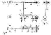
- Fig. 2a, 2b and 2c a very similar embodiment is shown, which in many parts of the embodiment of Fig. 1 equivalent. The only difference is in principle the shortened pipe connection 17.
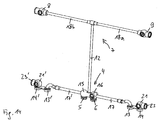
- Fig. 3a and 3b a further embodiment is shown, in which the alternative second flow connection 13 is arranged in the left lower end region of the radiator 1.
- the second alternative flow connection 13 via the pipe connection 17 is structurally not connected to the return housing 16, but both structurally and hydraulically laterally to the flow housing 15 and the heating medium can in this way either via the first flow connection 5 or via the second alternative flow connection 13 get into the riser 12.
- the further course of flow is analogous to that at Fig. 1 or 2.
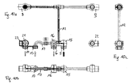
- a further embodiment is shown in which the second alternative flow connection 13 does not flow directly into the connection fitting 4, but is connected via a pipe connection 17 structurally and hydraulically directly to the riser 12.
- the pipe connection 17 accordingly opens just above the connection fitting 4 in the lowermost portion of the riser 12 and the heating medium flows in this way directly into the riser 12.
- the further flow is analogous here to the other embodiments.
- FIG. 5a and 5b Yet another embodiment is described in which in each case in the left and in the lower right corner region of the radiator 1 each alternate flow and return ports 13, 13 ', 14, 14' are provided. In principle, these are the embodiments of Fig. 2 and Fig. 3 provided at the same time.
- the second alternative flow connection 13 is structurally connected to the return housing 16, the third alternative flow connection 13 'via a further pipe connections 17' constructive to the flow housing 15. Hydraulically, both flow connections 13, 13 'connected to the riser 12. In this way, there is still a greater variety and variability and it can in this embodiment, three different Flow connections 5, 13, 13 'and three different return connections 6, 14, 14' are selected and combined with each other.
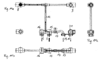
- FIG. 6 . 7 and 8th an alternative variant of this embodiment is shown.
- Fig. 6a and Fig. 7b are also sectional views through the connecting fitting 4 and through all flow ports 5, 13 'and 13 and return ports 6, 14, 14' shown. It can also be seen here how the pipe connection 17, via which the second alternative flow connection 13 is connected to the connection fitting 4, traverses the return flow housing 16 transversely and in this way represents the hydraulic connection to the flow or the riser pipe 12.
- the pipe connection 17 or 17 respectively represents the mechanical and hydraulic connection between the second, or each further, alternative flow connection 13, 13' with the central connection fitting 4.
- the pipe connection 17, 17 ' is here in two parts or Each has a releasable plug connection 19, 19 'or alternatively a fixed Bülstversch spaung, via which the connection can take place.
- first and further flow connections 5, 13, 13 'and return connections 6, 14, 14' lie in a common plane parallel to the first heating plate 2. All these connections are equidistant from this heating plate 2.
- connecting pieces 8, 9, the lateral connecting pieces 22 and the first and further return connections 6, 14, 14 ' are not as in the embodiments of the Fig. 1 to 8 designed as T-shaped components with cross connections to both heating plates 2 and 3, but each have only one connection to the first heating plate 2.
- radiators 1 The flow through these radiators 1 is analogous and although the heating medium flows through the first flow connection 5 or an alternative flow connection 13, 13 'to the distributor set 7 and from there via the connecting piece 8 with the valve 10 in the first heating plate 2. There, the heating medium distributed via the heating plate 2, decreases over the heating channels and leaves the radiator 1 via one of the return connections.
- the first return port 6, each further return port 14, 14 'or alternatively the lateral connecting port 22 or the end-side return port 23 are optionally available.
- This radiator 1 is configured as a three-layer radiator 1 with parallel flow and has three mutually parallel heating plates (2,3,30): a first room-side heating plate 2, a second wall-side heating plate 3 and a third even closer to the room than the first heating plate. 2
- the third heating plate 30 is fluidically and structurally connected to the first heating plate 2 via pipes 24.
- These tubes 24 are arranged in the upper and lower corner regions and aligned with the transverse tubes of the connecting pieces 8, 9, the lateral connecting piece 22 and the return connection piece 23, 23 'aligned.
- the entire connection set 4 and the entire distributor set 7 are located between the first heating plate 2 and the second heating plate 3.
Landscapes
- Engineering & Computer Science (AREA)
- Physics & Mathematics (AREA)
- Thermal Sciences (AREA)
- Chemical & Material Sciences (AREA)
- Combustion & Propulsion (AREA)
- Mechanical Engineering (AREA)
- General Engineering & Computer Science (AREA)
- Steam Or Hot-Water Central Heating Systems (AREA)
Priority Applications (1)
| Application Number | Priority Date | Filing Date | Title |
|---|---|---|---|
| PL16174931T PL3109561T3 (pl) | 2015-06-23 | 2016-06-17 | Grzejnik |
Applications Claiming Priority (1)
| Application Number | Priority Date | Filing Date | Title |
|---|---|---|---|
| ATA50527/2015A AT516831B1 (de) | 2015-06-23 | 2015-06-23 | Heizkörper |
Publications (2)
| Publication Number | Publication Date |
|---|---|
| EP3109561A1 true EP3109561A1 (fr) | 2016-12-28 |
| EP3109561B1 EP3109561B1 (fr) | 2019-09-11 |
Family
ID=56134230
Family Applications (1)
| Application Number | Title | Priority Date | Filing Date |
|---|---|---|---|
| EP16174931.2A Active EP3109561B1 (fr) | 2015-06-23 | 2016-06-17 | Radiateur |
Country Status (3)
| Country | Link |
|---|---|
| EP (1) | EP3109561B1 (fr) |
| AT (1) | AT516831B1 (fr) |
| PL (1) | PL3109561T3 (fr) |
Cited By (1)
| Publication number | Priority date | Publication date | Assignee | Title |
|---|---|---|---|---|
| EP3628935A1 (fr) | 2018-09-28 | 2020-04-01 | Rettig Austria GmbH | Radiateur |
Citations (6)
| Publication number | Priority date | Publication date | Assignee | Title |
|---|---|---|---|---|
| DE19539222C1 (de) | 1995-10-23 | 1997-04-24 | Baumann Gmbh | Heizkörperanordnung |
| DE10203313A1 (de) | 2002-01-29 | 2003-08-07 | Berg Hans Gmbh & Co Kg | Anschlussgarnitur für einen Plattenheizkörper |
| EP1965148A1 (fr) * | 2007-03-02 | 2008-09-03 | Van Marcke Logistics N.V. | Corps de chauffe |
| DE102007020628A1 (de) * | 2007-04-30 | 2008-11-06 | Hans Berg Gmbh & Co. Kg | Anschlussgarnitur für einen Plattenheizkörper |
| DE102010010541A1 (de) * | 2009-03-11 | 2011-03-03 | Hans Berg Gmbh & Co. Kg | Heizkörper und Stell- oder Ventileinrichtung zur Verwendung an einem Heizkörper |
| EP2428748A2 (fr) | 2010-09-14 | 2012-03-14 | Caradon Stelrad B.V. | Radiateur à panneaux et procédé de conduite d'un produit de chauffage |
-
2015
- 2015-06-23 AT ATA50527/2015A patent/AT516831B1/de active
-
2016
- 2016-06-17 EP EP16174931.2A patent/EP3109561B1/fr active Active
- 2016-06-17 PL PL16174931T patent/PL3109561T3/pl unknown
Patent Citations (6)
| Publication number | Priority date | Publication date | Assignee | Title |
|---|---|---|---|---|
| DE19539222C1 (de) | 1995-10-23 | 1997-04-24 | Baumann Gmbh | Heizkörperanordnung |
| DE10203313A1 (de) | 2002-01-29 | 2003-08-07 | Berg Hans Gmbh & Co Kg | Anschlussgarnitur für einen Plattenheizkörper |
| EP1965148A1 (fr) * | 2007-03-02 | 2008-09-03 | Van Marcke Logistics N.V. | Corps de chauffe |
| DE102007020628A1 (de) * | 2007-04-30 | 2008-11-06 | Hans Berg Gmbh & Co. Kg | Anschlussgarnitur für einen Plattenheizkörper |
| DE102010010541A1 (de) * | 2009-03-11 | 2011-03-03 | Hans Berg Gmbh & Co. Kg | Heizkörper und Stell- oder Ventileinrichtung zur Verwendung an einem Heizkörper |
| EP2428748A2 (fr) | 2010-09-14 | 2012-03-14 | Caradon Stelrad B.V. | Radiateur à panneaux et procédé de conduite d'un produit de chauffage |
Cited By (2)
| Publication number | Priority date | Publication date | Assignee | Title |
|---|---|---|---|---|
| EP3628935A1 (fr) | 2018-09-28 | 2020-04-01 | Rettig Austria GmbH | Radiateur |
| EP3628935B1 (fr) * | 2018-09-28 | 2023-06-07 | PG Austria GmbH | Radiateur |
Also Published As
| Publication number | Publication date |
|---|---|
| EP3109561B1 (fr) | 2019-09-11 |
| AT516831A4 (de) | 2016-09-15 |
| AT516831B1 (de) | 2016-09-15 |
| PL3109561T3 (pl) | 2020-06-29 |
Similar Documents
| Publication | Publication Date | Title |
|---|---|---|
| DE202009001056U1 (de) | Heizkreisverteiler | |
| AT411294B (de) | Heiz-(kühl-)körper | |
| EP3109561B1 (fr) | Radiateur | |
| AT521052B1 (de) | Heizkörper | |
| AT411933B (de) | Flachheizkörper | |
| DE19750109C2 (de) | Anschlußgarnitur und Heizkörper | |
| DE19744482C1 (de) | Anschlußsystem für Heizkörper | |
| DE19832051C2 (de) | Heiz- bzw. Kühlkörper-Verteileranordnung | |
| AT411394B (de) | Rohrheizkörper | |
| DE10223790B4 (de) | Plattenheizkörper | |
| CH693966A5 (de) | Heizkoerper und Anschlussgarnitur. | |
| AT409545B (de) | Heiz-(kühl-)körper | |
| EP3064879B1 (fr) | Dispositif de radiateur a ecoulement croise | |
| EP3067629B1 (fr) | Appareil de chauffage avec système de tuyauterie | |
| DE102006031406A1 (de) | Heizkörper, insbesondere Röhrenradiator | |
| EP3511634A1 (fr) | Kit de raccordement | |
| AT412122B (de) | Flachheizkörper | |
| AT500154B1 (de) | Anschlussarmatur | |
| DE29705694U1 (de) | Konvektor, Konvektorrohling und Konvektorbausatz | |
| DE102015208479A1 (de) | Heizkörpervorrichtung mit Kreuzdurchströmung | |
| DE10215704A1 (de) | Heizkörper | |
| WO2009015629A2 (fr) | Radiateur tubulaire | |
| DE202012007992U1 (de) | Anschlussvorrichtung für unteren Vorlaufanschluss | |
| DE10105373A1 (de) | Verbesserter Heizkörper | |
| DE20023737U1 (de) | Rohrheizkörper |
Legal Events
| Date | Code | Title | Description |
|---|---|---|---|
| PUAI | Public reference made under article 153(3) epc to a published international application that has entered the european phase |
Free format text: ORIGINAL CODE: 0009012 |
|
| STAA | Information on the status of an ep patent application or granted ep patent |
Free format text: STATUS: THE APPLICATION HAS BEEN PUBLISHED |
|
| AK | Designated contracting states |
Kind code of ref document: A1 Designated state(s): AL AT BE BG CH CY CZ DE DK EE ES FI FR GB GR HR HU IE IS IT LI LT LU LV MC MK MT NL NO PL PT RO RS SE SI SK SM TR |
|
| AX | Request for extension of the european patent |
Extension state: BA ME |
|
| STAA | Information on the status of an ep patent application or granted ep patent |
Free format text: STATUS: REQUEST FOR EXAMINATION WAS MADE |
|
| 17P | Request for examination filed |
Effective date: 20170626 |
|
| RBV | Designated contracting states (corrected) |
Designated state(s): AL AT BE BG CH CY CZ DE DK EE ES FI FR GB GR HR HU IE IS IT LI LT LU LV MC MK MT NL NO PL PT RO RS SE SI SK SM TR |
|
| STAA | Information on the status of an ep patent application or granted ep patent |
Free format text: STATUS: EXAMINATION IS IN PROGRESS |
|
| 17Q | First examination report despatched |
Effective date: 20171221 |
|
| GRAP | Despatch of communication of intention to grant a patent |
Free format text: ORIGINAL CODE: EPIDOSNIGR1 |
|
| STAA | Information on the status of an ep patent application or granted ep patent |
Free format text: STATUS: GRANT OF PATENT IS INTENDED |
|
| INTG | Intention to grant announced |
Effective date: 20190404 |
|
| GRAS | Grant fee paid |
Free format text: ORIGINAL CODE: EPIDOSNIGR3 |
|
| GRAA | (expected) grant |
Free format text: ORIGINAL CODE: 0009210 |
|
| STAA | Information on the status of an ep patent application or granted ep patent |
Free format text: STATUS: THE PATENT HAS BEEN GRANTED |
|
| AK | Designated contracting states |
Kind code of ref document: B1 Designated state(s): AL AT BE BG CH CY CZ DE DK EE ES FI FR GB GR HR HU IE IS IT LI LT LU LV MC MK MT NL NO PL PT RO RS SE SI SK SM TR |
|
| REG | Reference to a national code |
Ref country code: GB Ref legal event code: FG4D Free format text: NOT ENGLISH |
|
| REG | Reference to a national code |
Ref country code: CH Ref legal event code: EP |
|
| REG | Reference to a national code |
Ref country code: AT Ref legal event code: REF Ref document number: 1178919 Country of ref document: AT Kind code of ref document: T Effective date: 20190915 |
|
| REG | Reference to a national code |
Ref country code: DE Ref legal event code: R096 Ref document number: 502016006522 Country of ref document: DE Ref country code: IE Ref legal event code: FG4D Free format text: LANGUAGE OF EP DOCUMENT: GERMAN |
|
| REG | Reference to a national code |
Ref country code: NL Ref legal event code: FP |
|
| REG | Reference to a national code |
Ref country code: LT Ref legal event code: MG4D |
|
| PG25 | Lapsed in a contracting state [announced via postgrant information from national office to epo] |
Ref country code: FI Free format text: LAPSE BECAUSE OF FAILURE TO SUBMIT A TRANSLATION OF THE DESCRIPTION OR TO PAY THE FEE WITHIN THE PRESCRIBED TIME-LIMIT Effective date: 20190911 Ref country code: LT Free format text: LAPSE BECAUSE OF FAILURE TO SUBMIT A TRANSLATION OF THE DESCRIPTION OR TO PAY THE FEE WITHIN THE PRESCRIBED TIME-LIMIT Effective date: 20190911 Ref country code: BG Free format text: LAPSE BECAUSE OF FAILURE TO SUBMIT A TRANSLATION OF THE DESCRIPTION OR TO PAY THE FEE WITHIN THE PRESCRIBED TIME-LIMIT Effective date: 20191211 Ref country code: NO Free format text: LAPSE BECAUSE OF FAILURE TO SUBMIT A TRANSLATION OF THE DESCRIPTION OR TO PAY THE FEE WITHIN THE PRESCRIBED TIME-LIMIT Effective date: 20191211 Ref country code: HR Free format text: LAPSE BECAUSE OF FAILURE TO SUBMIT A TRANSLATION OF THE DESCRIPTION OR TO PAY THE FEE WITHIN THE PRESCRIBED TIME-LIMIT Effective date: 20190911 Ref country code: SE Free format text: LAPSE BECAUSE OF FAILURE TO SUBMIT A TRANSLATION OF THE DESCRIPTION OR TO PAY THE FEE WITHIN THE PRESCRIBED TIME-LIMIT Effective date: 20190911 |
|
| PG25 | Lapsed in a contracting state [announced via postgrant information from national office to epo] |
Ref country code: RS Free format text: LAPSE BECAUSE OF FAILURE TO SUBMIT A TRANSLATION OF THE DESCRIPTION OR TO PAY THE FEE WITHIN THE PRESCRIBED TIME-LIMIT Effective date: 20190911 Ref country code: GR Free format text: LAPSE BECAUSE OF FAILURE TO SUBMIT A TRANSLATION OF THE DESCRIPTION OR TO PAY THE FEE WITHIN THE PRESCRIBED TIME-LIMIT Effective date: 20191212 Ref country code: ES Free format text: LAPSE BECAUSE OF FAILURE TO SUBMIT A TRANSLATION OF THE DESCRIPTION OR TO PAY THE FEE WITHIN THE PRESCRIBED TIME-LIMIT Effective date: 20190911 Ref country code: LV Free format text: LAPSE BECAUSE OF FAILURE TO SUBMIT A TRANSLATION OF THE DESCRIPTION OR TO PAY THE FEE WITHIN THE PRESCRIBED TIME-LIMIT Effective date: 20190911 Ref country code: AL Free format text: LAPSE BECAUSE OF FAILURE TO SUBMIT A TRANSLATION OF THE DESCRIPTION OR TO PAY THE FEE WITHIN THE PRESCRIBED TIME-LIMIT Effective date: 20190911 |
|
| PG25 | Lapsed in a contracting state [announced via postgrant information from national office to epo] |
Ref country code: EE Free format text: LAPSE BECAUSE OF FAILURE TO SUBMIT A TRANSLATION OF THE DESCRIPTION OR TO PAY THE FEE WITHIN THE PRESCRIBED TIME-LIMIT Effective date: 20190911 Ref country code: IT Free format text: LAPSE BECAUSE OF FAILURE TO SUBMIT A TRANSLATION OF THE DESCRIPTION OR TO PAY THE FEE WITHIN THE PRESCRIBED TIME-LIMIT Effective date: 20190911 Ref country code: RO Free format text: LAPSE BECAUSE OF FAILURE TO SUBMIT A TRANSLATION OF THE DESCRIPTION OR TO PAY THE FEE WITHIN THE PRESCRIBED TIME-LIMIT Effective date: 20190911 Ref country code: PT Free format text: LAPSE BECAUSE OF FAILURE TO SUBMIT A TRANSLATION OF THE DESCRIPTION OR TO PAY THE FEE WITHIN THE PRESCRIBED TIME-LIMIT Effective date: 20200113 |
|
| PG25 | Lapsed in a contracting state [announced via postgrant information from national office to epo] |
Ref country code: SK Free format text: LAPSE BECAUSE OF FAILURE TO SUBMIT A TRANSLATION OF THE DESCRIPTION OR TO PAY THE FEE WITHIN THE PRESCRIBED TIME-LIMIT Effective date: 20190911 Ref country code: CZ Free format text: LAPSE BECAUSE OF FAILURE TO SUBMIT A TRANSLATION OF THE DESCRIPTION OR TO PAY THE FEE WITHIN THE PRESCRIBED TIME-LIMIT Effective date: 20190911 Ref country code: IS Free format text: LAPSE BECAUSE OF FAILURE TO SUBMIT A TRANSLATION OF THE DESCRIPTION OR TO PAY THE FEE WITHIN THE PRESCRIBED TIME-LIMIT Effective date: 20200224 Ref country code: SM Free format text: LAPSE BECAUSE OF FAILURE TO SUBMIT A TRANSLATION OF THE DESCRIPTION OR TO PAY THE FEE WITHIN THE PRESCRIBED TIME-LIMIT Effective date: 20190911 |
|
| REG | Reference to a national code |
Ref country code: DE Ref legal event code: R097 Ref document number: 502016006522 Country of ref document: DE |
|
| PLBE | No opposition filed within time limit |
Free format text: ORIGINAL CODE: 0009261 |
|
| STAA | Information on the status of an ep patent application or granted ep patent |
Free format text: STATUS: NO OPPOSITION FILED WITHIN TIME LIMIT |
|
| PG2D | Information on lapse in contracting state deleted |
Ref country code: IS |
|
| PG25 | Lapsed in a contracting state [announced via postgrant information from national office to epo] |
Ref country code: DK Free format text: LAPSE BECAUSE OF FAILURE TO SUBMIT A TRANSLATION OF THE DESCRIPTION OR TO PAY THE FEE WITHIN THE PRESCRIBED TIME-LIMIT Effective date: 20190911 Ref country code: IS Free format text: LAPSE BECAUSE OF FAILURE TO SUBMIT A TRANSLATION OF THE DESCRIPTION OR TO PAY THE FEE WITHIN THE PRESCRIBED TIME-LIMIT Effective date: 20200112 |
|
| 26N | No opposition filed |
Effective date: 20200615 |
|
| PG25 | Lapsed in a contracting state [announced via postgrant information from national office to epo] |
Ref country code: SI Free format text: LAPSE BECAUSE OF FAILURE TO SUBMIT A TRANSLATION OF THE DESCRIPTION OR TO PAY THE FEE WITHIN THE PRESCRIBED TIME-LIMIT Effective date: 20190911 |
|
| PG25 | Lapsed in a contracting state [announced via postgrant information from national office to epo] |
Ref country code: MC Free format text: LAPSE BECAUSE OF FAILURE TO SUBMIT A TRANSLATION OF THE DESCRIPTION OR TO PAY THE FEE WITHIN THE PRESCRIBED TIME-LIMIT Effective date: 20190911 |
|
| REG | Reference to a national code |
Ref country code: CH Ref legal event code: PL |
|
| PG25 | Lapsed in a contracting state [announced via postgrant information from national office to epo] |
Ref country code: IE Free format text: LAPSE BECAUSE OF NON-PAYMENT OF DUE FEES Effective date: 20200617 Ref country code: CH Free format text: LAPSE BECAUSE OF NON-PAYMENT OF DUE FEES Effective date: 20200630 Ref country code: LI Free format text: LAPSE BECAUSE OF NON-PAYMENT OF DUE FEES Effective date: 20200630 |
|
| REG | Reference to a national code |
Ref country code: DE Ref legal event code: R081 Ref document number: 502016006522 Country of ref document: DE Owner name: PURMO GROUP OY AB, FI Free format text: FORMER OWNER: RETTIG ICC B.V., MAASTRICHT-AIRPORT, NL |
|
| REG | Reference to a national code |
Ref country code: LU Ref legal event code: PD Owner name: PURMO GROUP OY AB; FI Free format text: FORMER OWNER: RETTIG ICC B.V. Effective date: 20210915 |
|
| REG | Reference to a national code |
Ref country code: NL Ref legal event code: PD Owner name: PURMO GROUP OY AB; FI Free format text: DETAILS ASSIGNMENT: CHANGE OF OWNER(S), MERGE; FORMER OWNER NAME: RETTIG ICC B.V. Effective date: 20210923 |
|
| REG | Reference to a national code |
Ref country code: GB Ref legal event code: 732E Free format text: REGISTERED BETWEEN 20210930 AND 20211006 |
|
| PG25 | Lapsed in a contracting state [announced via postgrant information from national office to epo] |
Ref country code: TR Free format text: LAPSE BECAUSE OF FAILURE TO SUBMIT A TRANSLATION OF THE DESCRIPTION OR TO PAY THE FEE WITHIN THE PRESCRIBED TIME-LIMIT Effective date: 20190911 Ref country code: MT Free format text: LAPSE BECAUSE OF FAILURE TO SUBMIT A TRANSLATION OF THE DESCRIPTION OR TO PAY THE FEE WITHIN THE PRESCRIBED TIME-LIMIT Effective date: 20190911 Ref country code: CY Free format text: LAPSE BECAUSE OF FAILURE TO SUBMIT A TRANSLATION OF THE DESCRIPTION OR TO PAY THE FEE WITHIN THE PRESCRIBED TIME-LIMIT Effective date: 20190911 |
|
| PG25 | Lapsed in a contracting state [announced via postgrant information from national office to epo] |
Ref country code: MK Free format text: LAPSE BECAUSE OF FAILURE TO SUBMIT A TRANSLATION OF THE DESCRIPTION OR TO PAY THE FEE WITHIN THE PRESCRIBED TIME-LIMIT Effective date: 20190911 |
|
| REG | Reference to a national code |
Ref country code: AT Ref legal event code: MM01 Ref document number: 1178919 Country of ref document: AT Kind code of ref document: T Effective date: 20210617 |
|
| PG25 | Lapsed in a contracting state [announced via postgrant information from national office to epo] |
Ref country code: AT Free format text: LAPSE BECAUSE OF NON-PAYMENT OF DUE FEES Effective date: 20210617 |
|
| PGFP | Annual fee paid to national office [announced via postgrant information from national office to epo] |
Ref country code: PL Payment date: 20250606 Year of fee payment: 10 Ref country code: DE Payment date: 20250618 Year of fee payment: 10 |
|
| PGFP | Annual fee paid to national office [announced via postgrant information from national office to epo] |
Ref country code: GB Payment date: 20250618 Year of fee payment: 10 |
|
| PGFP | Annual fee paid to national office [announced via postgrant information from national office to epo] |
Ref country code: LU Payment date: 20250627 Year of fee payment: 10 Ref country code: NL Payment date: 20250618 Year of fee payment: 10 Ref country code: BE Payment date: 20250618 Year of fee payment: 10 |
|
| PGFP | Annual fee paid to national office [announced via postgrant information from national office to epo] |
Ref country code: FR Payment date: 20250625 Year of fee payment: 10 |