EP3109629A2 - Capteur avec mémoire stockant des informations d'étalonnage - Google Patents
Capteur avec mémoire stockant des informations d'étalonnage Download PDFInfo
- Publication number
- EP3109629A2 EP3109629A2 EP16164301.0A EP16164301A EP3109629A2 EP 3109629 A2 EP3109629 A2 EP 3109629A2 EP 16164301 A EP16164301 A EP 16164301A EP 3109629 A2 EP3109629 A2 EP 3109629A2
- Authority
- EP
- European Patent Office
- Prior art keywords
- sensor
- aqueous liquid
- temperature
- signal
- controller
- Prior art date
- Legal status (The legal status is an assumption and is not a legal conclusion. Google has not performed a legal analysis and makes no representation as to the accuracy of the status listed.)
- Withdrawn
Links
- 239000007788 liquid Substances 0.000 claims abstract description 131
- ZAMOUSCENKQFHK-UHFFFAOYSA-N Chlorine atom Chemical compound [Cl] ZAMOUSCENKQFHK-UHFFFAOYSA-N 0.000 claims description 126
- 239000000460 chlorine Substances 0.000 claims description 126
- 229910052801 chlorine Inorganic materials 0.000 claims description 126
- 239000002253 acid Substances 0.000 claims description 32
- 150000003839 salts Chemical class 0.000 claims description 19
- 238000005259 measurement Methods 0.000 claims description 14
- 239000007787 solid Substances 0.000 claims description 13
- BASFCYQUMIYNBI-UHFFFAOYSA-N platinum Chemical compound [Pt] BASFCYQUMIYNBI-UHFFFAOYSA-N 0.000 claims description 12
- QVGXLLKOCUKJST-UHFFFAOYSA-N atomic oxygen Chemical compound [O] QVGXLLKOCUKJST-UHFFFAOYSA-N 0.000 claims description 11
- 229910052760 oxygen Inorganic materials 0.000 claims description 11
- 239000001301 oxygen Substances 0.000 claims description 11
- 230000004888 barrier function Effects 0.000 claims description 10
- 239000012528 membrane Substances 0.000 claims description 10
- 150000001450 anions Chemical class 0.000 claims description 8
- 230000001590 oxidative effect Effects 0.000 claims description 7
- 229910052697 platinum Inorganic materials 0.000 claims description 6
- 229910052736 halogen Inorganic materials 0.000 claims description 5
- 150000002367 halogens Chemical class 0.000 claims description 5
- 229910052751 metal Inorganic materials 0.000 claims description 5
- 239000002184 metal Substances 0.000 claims description 5
- PCHJSUWPFVWCPO-UHFFFAOYSA-N gold Chemical compound [Au] PCHJSUWPFVWCPO-UHFFFAOYSA-N 0.000 claims description 4
- 229910052737 gold Inorganic materials 0.000 claims description 4
- 239000010931 gold Substances 0.000 claims description 4
- 229910052787 antimony Inorganic materials 0.000 claims description 3
- WATWJIUSRGPENY-UHFFFAOYSA-N antimony atom Chemical compound [Sb] WATWJIUSRGPENY-UHFFFAOYSA-N 0.000 claims description 3
- 229910052739 hydrogen Inorganic materials 0.000 claims description 3
- 239000001257 hydrogen Substances 0.000 claims description 3
- -1 hydrogen ions Chemical class 0.000 claims description 3
- 238000012545 processing Methods 0.000 claims description 3
- 229910000410 antimony oxide Inorganic materials 0.000 claims description 2
- 229910052797 bismuth Inorganic materials 0.000 claims description 2
- JCXGWMGPZLAOME-UHFFFAOYSA-N bismuth atom Chemical compound [Bi] JCXGWMGPZLAOME-UHFFFAOYSA-N 0.000 claims description 2
- 229910000416 bismuth oxide Inorganic materials 0.000 claims description 2
- 238000006243 chemical reaction Methods 0.000 claims description 2
- TYIXMATWDRGMPF-UHFFFAOYSA-N dibismuth;oxygen(2-) Chemical compound [O-2].[O-2].[O-2].[Bi+3].[Bi+3] TYIXMATWDRGMPF-UHFFFAOYSA-N 0.000 claims description 2
- 230000005465 channeling Effects 0.000 claims 3
- XLYOFNOQVPJJNP-UHFFFAOYSA-N water Substances O XLYOFNOQVPJJNP-UHFFFAOYSA-N 0.000 description 60
- 239000000243 solution Substances 0.000 description 17
- FAPWRFPIFSIZLT-UHFFFAOYSA-M Sodium chloride Chemical compound [Na+].[Cl-] FAPWRFPIFSIZLT-UHFFFAOYSA-M 0.000 description 16
- 239000000126 substance Substances 0.000 description 14
- CURLTUGMZLYLDI-UHFFFAOYSA-N Carbon dioxide Chemical compound O=C=O CURLTUGMZLYLDI-UHFFFAOYSA-N 0.000 description 13
- QWPPOHNGKGFGJK-UHFFFAOYSA-N hypochlorous acid Chemical compound ClO QWPPOHNGKGFGJK-UHFFFAOYSA-N 0.000 description 11
- 238000000034 method Methods 0.000 description 10
- VEXZGXHMUGYJMC-UHFFFAOYSA-N Hydrochloric acid Chemical compound Cl VEXZGXHMUGYJMC-UHFFFAOYSA-N 0.000 description 9
- 230000009182 swimming Effects 0.000 description 9
- 239000001569 carbon dioxide Substances 0.000 description 8
- 229910002092 carbon dioxide Inorganic materials 0.000 description 8
- 239000011780 sodium chloride Substances 0.000 description 8
- 238000010586 diagram Methods 0.000 description 7
- WKBOTKDWSSQWDR-UHFFFAOYSA-N Bromine atom Chemical compound [Br] WKBOTKDWSSQWDR-UHFFFAOYSA-N 0.000 description 6
- GDTBXPJZTBHREO-UHFFFAOYSA-N bromine Substances BrBr GDTBXPJZTBHREO-UHFFFAOYSA-N 0.000 description 6
- 229910052794 bromium Inorganic materials 0.000 description 6
- 229910052799 carbon Inorganic materials 0.000 description 6
- 230000001419 dependent effect Effects 0.000 description 6
- WQYVRQLZKVEZGA-UHFFFAOYSA-N hypochlorite Chemical compound Cl[O-] WQYVRQLZKVEZGA-UHFFFAOYSA-N 0.000 description 6
- 238000004891 communication Methods 0.000 description 5
- 229920001577 copolymer Polymers 0.000 description 5
- 230000006870 function Effects 0.000 description 5
- 235000011167 hydrochloric acid Nutrition 0.000 description 5
- 230000008569 process Effects 0.000 description 5
- SUKJFIGYRHOWBL-UHFFFAOYSA-N sodium hypochlorite Chemical compound [Na+].Cl[O-] SUKJFIGYRHOWBL-UHFFFAOYSA-N 0.000 description 5
- 239000012085 test solution Substances 0.000 description 5
- BFKJFAAPBSQJPD-UHFFFAOYSA-N tetrafluoroethene Chemical group FC(F)=C(F)F BFKJFAAPBSQJPD-UHFFFAOYSA-N 0.000 description 5
- XEEYBQQBJWHFJM-UHFFFAOYSA-N Iron Chemical compound [Fe] XEEYBQQBJWHFJM-UHFFFAOYSA-N 0.000 description 4
- BVKZGUZCCUSVTD-UHFFFAOYSA-N carbonic acid Chemical compound OC(O)=O BVKZGUZCCUSVTD-UHFFFAOYSA-N 0.000 description 4
- 238000012544 monitoring process Methods 0.000 description 4
- 238000012360 testing method Methods 0.000 description 4
- 239000005708 Sodium hypochlorite Substances 0.000 description 3
- 238000010276 construction Methods 0.000 description 3
- 230000000694 effects Effects 0.000 description 3
- CUILPNURFADTPE-UHFFFAOYSA-N hypobromous acid Chemical compound BrO CUILPNURFADTPE-UHFFFAOYSA-N 0.000 description 3
- 239000007800 oxidant agent Substances 0.000 description 3
- 230000033116 oxidation-reduction process Effects 0.000 description 3
- 239000000523 sample Substances 0.000 description 3
- JHJLBTNAGRQEKS-UHFFFAOYSA-M sodium bromide Chemical compound [Na+].[Br-] JHJLBTNAGRQEKS-UHFFFAOYSA-M 0.000 description 3
- 238000006467 substitution reaction Methods 0.000 description 3
- UXVMQQNJUSDDNG-UHFFFAOYSA-L Calcium chloride Chemical compound [Cl-].[Cl-].[Ca+2] UXVMQQNJUSDDNG-UHFFFAOYSA-L 0.000 description 2
- RYGMFSIKBFXOCR-UHFFFAOYSA-N Copper Chemical compound [Cu] RYGMFSIKBFXOCR-UHFFFAOYSA-N 0.000 description 2
- 241000195493 Cryptophyta Species 0.000 description 2
- 229910019093 NaOCl Inorganic materials 0.000 description 2
- 230000009471 action Effects 0.000 description 2
- 244000052616 bacterial pathogen Species 0.000 description 2
- 230000008901 benefit Effects 0.000 description 2
- 229910001628 calcium chloride Inorganic materials 0.000 description 2
- 239000001110 calcium chloride Substances 0.000 description 2
- 229910052802 copper Inorganic materials 0.000 description 2
- 239000010949 copper Substances 0.000 description 2
- 239000000645 desinfectant Substances 0.000 description 2
- 238000005868 electrolysis reaction Methods 0.000 description 2
- 239000013505 freshwater Substances 0.000 description 2
- 239000011521 glass Substances 0.000 description 2
- 229910052742 iron Inorganic materials 0.000 description 2
- WPBNNNQJVZRUHP-UHFFFAOYSA-L manganese(2+);methyl n-[[2-(methoxycarbonylcarbamothioylamino)phenyl]carbamothioyl]carbamate;n-[2-(sulfidocarbothioylamino)ethyl]carbamodithioate Chemical compound [Mn+2].[S-]C(=S)NCCNC([S-])=S.COC(=O)NC(=S)NC1=CC=CC=C1NC(=S)NC(=O)OC WPBNNNQJVZRUHP-UHFFFAOYSA-L 0.000 description 2
- 238000004519 manufacturing process Methods 0.000 description 2
- 239000000463 material Substances 0.000 description 2
- 239000000203 mixture Substances 0.000 description 2
- 238000012986 modification Methods 0.000 description 2
- 230000004048 modification Effects 0.000 description 2
- 230000009467 reduction Effects 0.000 description 2
- 238000011012 sanitization Methods 0.000 description 2
- 239000002699 waste material Substances 0.000 description 2
- OYPRJOBELJOOCE-UHFFFAOYSA-N Calcium Chemical compound [Ca] OYPRJOBELJOOCE-UHFFFAOYSA-N 0.000 description 1
- ZKQDCIXGCQPQNV-UHFFFAOYSA-N Calcium hypochlorite Chemical compound [Ca+2].Cl[O-].Cl[O-] ZKQDCIXGCQPQNV-UHFFFAOYSA-N 0.000 description 1
- 206010012735 Diarrhoea Diseases 0.000 description 1
- 206010015946 Eye irritation Diseases 0.000 description 1
- 229910021607 Silver chloride Inorganic materials 0.000 description 1
- 206010040880 Skin irritation Diseases 0.000 description 1
- 230000002378 acidificating effect Effects 0.000 description 1
- 150000007513 acids Chemical class 0.000 description 1
- 230000006978 adaptation Effects 0.000 description 1
- 239000012491 analyte Substances 0.000 description 1
- 239000007864 aqueous solution Substances 0.000 description 1
- 238000013475 authorization Methods 0.000 description 1
- 239000007844 bleaching agent Substances 0.000 description 1
- 230000003139 buffering effect Effects 0.000 description 1
- 239000011575 calcium Substances 0.000 description 1
- 229910052791 calcium Inorganic materials 0.000 description 1
- 239000007894 caplet Substances 0.000 description 1
- 230000008859 change Effects 0.000 description 1
- 239000003795 chemical substances by application Substances 0.000 description 1
- 239000004020 conductor Substances 0.000 description 1
- 238000001816 cooling Methods 0.000 description 1
- 238000010790 dilution Methods 0.000 description 1
- 239000012895 dilution Substances 0.000 description 1
- 239000012153 distilled water Substances 0.000 description 1
- 238000002848 electrochemical method Methods 0.000 description 1
- 238000005516 engineering process Methods 0.000 description 1
- 230000005284 excitation Effects 0.000 description 1
- 231100000013 eye irritation Toxicity 0.000 description 1
- 239000012530 fluid Substances 0.000 description 1
- 238000005187 foaming Methods 0.000 description 1
- 230000005484 gravity Effects 0.000 description 1
- 230000036541 health Effects 0.000 description 1
- 229910000041 hydrogen chloride Inorganic materials 0.000 description 1
- IXCSERBJSXMMFS-UHFFFAOYSA-N hydrogen chloride Substances Cl.Cl IXCSERBJSXMMFS-UHFFFAOYSA-N 0.000 description 1
- JGJLWPGRMCADHB-UHFFFAOYSA-N hypobromite Chemical compound Br[O-] JGJLWPGRMCADHB-UHFFFAOYSA-N 0.000 description 1
- 229910052500 inorganic mineral Inorganic materials 0.000 description 1
- 230000007774 longterm Effects 0.000 description 1
- 238000012423 maintenance Methods 0.000 description 1
- 230000005055 memory storage Effects 0.000 description 1
- 150000002739 metals Chemical class 0.000 description 1
- 239000011707 mineral Substances 0.000 description 1
- 230000007935 neutral effect Effects 0.000 description 1
- 235000019645 odor Nutrition 0.000 description 1
- 150000002894 organic compounds Chemical class 0.000 description 1
- 230000008520 organization Effects 0.000 description 1
- 206010033072 otitis externa Diseases 0.000 description 1
- 230000003647 oxidation Effects 0.000 description 1
- 238000007254 oxidation reaction Methods 0.000 description 1
- 239000006174 pH buffer Substances 0.000 description 1
- 230000002572 peristaltic effect Effects 0.000 description 1
- IQDRAVRWQIIASA-VZPOTTSCSA-N phlorin Chemical compound C/1=C(N2)\C=C\C2=C\C(N2)=CC=C2CC(N2)=CC=C2\C=C2\C=CC\1=N2 IQDRAVRWQIIASA-VZPOTTSCSA-N 0.000 description 1
- 239000011505 plaster Substances 0.000 description 1
- 238000001556 precipitation Methods 0.000 description 1
- BDJXVNRFAQSMAA-UHFFFAOYSA-N quinhydrone Chemical compound OC1=CC=C(O)C=C1.O=C1C=CC(=O)C=C1 BDJXVNRFAQSMAA-UHFFFAOYSA-N 0.000 description 1
- 229940052881 quinhydrone Drugs 0.000 description 1
- 238000005070 sampling Methods 0.000 description 1
- 238000007789 sealing Methods 0.000 description 1
- 239000004065 semiconductor Substances 0.000 description 1
- 229910052709 silver Inorganic materials 0.000 description 1
- 239000004332 silver Substances 0.000 description 1
- HKZLPVFGJNLROG-UHFFFAOYSA-M silver monochloride Chemical compound [Cl-].[Ag+] HKZLPVFGJNLROG-UHFFFAOYSA-M 0.000 description 1
- 206010040872 skin infection Diseases 0.000 description 1
- 230000036556 skin irritation Effects 0.000 description 1
- 231100000475 skin irritation Toxicity 0.000 description 1
- 229910000679 solder Inorganic materials 0.000 description 1
- 239000007921 spray Substances 0.000 description 1
- 239000003381 stabilizer Substances 0.000 description 1
- 238000010561 standard procedure Methods 0.000 description 1
- 239000003826 tablet Substances 0.000 description 1
- 244000052613 viral pathogen Species 0.000 description 1
- 230000003612 virological effect Effects 0.000 description 1
Images




Classifications
-
- C—CHEMISTRY; METALLURGY
- C02—TREATMENT OF WATER, WASTE WATER, SEWAGE, OR SLUDGE
- C02F—TREATMENT OF WATER, WASTE WATER, SEWAGE, OR SLUDGE
- C02F1/00—Treatment of water, waste water, or sewage
- C02F1/66—Treatment of water, waste water, or sewage by neutralisation; pH adjustment
-
- C—CHEMISTRY; METALLURGY
- C02—TREATMENT OF WATER, WASTE WATER, SEWAGE, OR SLUDGE
- C02F—TREATMENT OF WATER, WASTE WATER, SEWAGE, OR SLUDGE
- C02F1/00—Treatment of water, waste water, or sewage
- C02F1/72—Treatment of water, waste water, or sewage by oxidation
- C02F1/76—Treatment of water, waste water, or sewage by oxidation with halogens or compounds of halogens
-
- G—PHYSICS
- G01—MEASURING; TESTING
- G01N—INVESTIGATING OR ANALYSING MATERIALS BY DETERMINING THEIR CHEMICAL OR PHYSICAL PROPERTIES
- G01N27/00—Investigating or analysing materials by the use of electric, electrochemical, or magnetic means
- G01N27/26—Investigating or analysing materials by the use of electric, electrochemical, or magnetic means by investigating electrochemical variables; by using electrolysis or electrophoresis
- G01N27/416—Systems
- G01N27/4163—Systems checking the operation of, or calibrating, the measuring apparatus
-
- G—PHYSICS
- G01—MEASURING; TESTING
- G01N—INVESTIGATING OR ANALYSING MATERIALS BY DETERMINING THEIR CHEMICAL OR PHYSICAL PROPERTIES
- G01N27/00—Investigating or analysing materials by the use of electric, electrochemical, or magnetic means
- G01N27/26—Investigating or analysing materials by the use of electric, electrochemical, or magnetic means by investigating electrochemical variables; by using electrolysis or electrophoresis
- G01N27/416—Systems
- G01N27/4166—Systems measuring a particular property of an electrolyte
-
- C—CHEMISTRY; METALLURGY
- C02—TREATMENT OF WATER, WASTE WATER, SEWAGE, OR SLUDGE
- C02F—TREATMENT OF WATER, WASTE WATER, SEWAGE, OR SLUDGE
- C02F2103/00—Nature of the water, waste water, sewage or sludge to be treated
- C02F2103/42—Nature of the water, waste water, sewage or sludge to be treated from bathing facilities, e.g. swimming pools
-
- C—CHEMISTRY; METALLURGY
- C02—TREATMENT OF WATER, WASTE WATER, SEWAGE, OR SLUDGE
- C02F—TREATMENT OF WATER, WASTE WATER, SEWAGE, OR SLUDGE
- C02F2209/00—Controlling or monitoring parameters in water treatment
- C02F2209/005—Processes using a programmable logic controller [PLC]
-
- C—CHEMISTRY; METALLURGY
- C02—TREATMENT OF WATER, WASTE WATER, SEWAGE, OR SLUDGE
- C02F—TREATMENT OF WATER, WASTE WATER, SEWAGE, OR SLUDGE
- C02F2209/00—Controlling or monitoring parameters in water treatment
- C02F2209/02—Temperature
-
- C—CHEMISTRY; METALLURGY
- C02—TREATMENT OF WATER, WASTE WATER, SEWAGE, OR SLUDGE
- C02F—TREATMENT OF WATER, WASTE WATER, SEWAGE, OR SLUDGE
- C02F2209/00—Controlling or monitoring parameters in water treatment
- C02F2209/04—Oxidation reduction potential [ORP]
-
- C—CHEMISTRY; METALLURGY
- C02—TREATMENT OF WATER, WASTE WATER, SEWAGE, OR SLUDGE
- C02F—TREATMENT OF WATER, WASTE WATER, SEWAGE, OR SLUDGE
- C02F2209/00—Controlling or monitoring parameters in water treatment
- C02F2209/06—Controlling or monitoring parameters in water treatment pH
-
- C—CHEMISTRY; METALLURGY
- C02—TREATMENT OF WATER, WASTE WATER, SEWAGE, OR SLUDGE
- C02F—TREATMENT OF WATER, WASTE WATER, SEWAGE, OR SLUDGE
- C02F2209/00—Controlling or monitoring parameters in water treatment
- C02F2209/10—Solids, e.g. total solids [TS], total suspended solids [TSS] or volatile solids [VS]
-
- C—CHEMISTRY; METALLURGY
- C02—TREATMENT OF WATER, WASTE WATER, SEWAGE, OR SLUDGE
- C02F—TREATMENT OF WATER, WASTE WATER, SEWAGE, OR SLUDGE
- C02F2209/00—Controlling or monitoring parameters in water treatment
- C02F2209/29—Chlorine compounds
-
- C—CHEMISTRY; METALLURGY
- C02—TREATMENT OF WATER, WASTE WATER, SEWAGE, OR SLUDGE
- C02F—TREATMENT OF WATER, WASTE WATER, SEWAGE, OR SLUDGE
- C02F2209/00—Controlling or monitoring parameters in water treatment
- C02F2209/42—Liquid level
-
- C—CHEMISTRY; METALLURGY
- C02—TREATMENT OF WATER, WASTE WATER, SEWAGE, OR SLUDGE
- C02F—TREATMENT OF WATER, WASTE WATER, SEWAGE, OR SLUDGE
- C02F2303/00—Specific treatment goals
- C02F2303/04—Disinfection
-
- G—PHYSICS
- G01—MEASURING; TESTING
- G01N—INVESTIGATING OR ANALYSING MATERIALS BY DETERMINING THEIR CHEMICAL OR PHYSICAL PROPERTIES
- G01N27/00—Investigating or analysing materials by the use of electric, electrochemical, or magnetic means
- G01N27/26—Investigating or analysing materials by the use of electric, electrochemical, or magnetic means by investigating electrochemical variables; by using electrolysis or electrophoresis
- G01N27/416—Systems
- G01N27/4163—Systems checking the operation of, or calibrating, the measuring apparatus
- G01N27/4165—Systems checking the operation of, or calibrating, the measuring apparatus for pH meters
-
- G—PHYSICS
- G01—MEASURING; TESTING
- G01N—INVESTIGATING OR ANALYSING MATERIALS BY DETERMINING THEIR CHEMICAL OR PHYSICAL PROPERTIES
- G01N27/00—Investigating or analysing materials by the use of electric, electrochemical, or magnetic means
- G01N27/26—Investigating or analysing materials by the use of electric, electrochemical, or magnetic means by investigating electrochemical variables; by using electrolysis or electrophoresis
- G01N27/416—Systems
- G01N27/4166—Systems measuring a particular property of an electrolyte
- G01N27/4167—Systems measuring a particular property of an electrolyte pH
-
- G—PHYSICS
- G01—MEASURING; TESTING
- G01N—INVESTIGATING OR ANALYSING MATERIALS BY DETERMINING THEIR CHEMICAL OR PHYSICAL PROPERTIES
- G01N27/00—Investigating or analysing materials by the use of electric, electrochemical, or magnetic means
- G01N27/26—Investigating or analysing materials by the use of electric, electrochemical, or magnetic means by investigating electrochemical variables; by using electrolysis or electrophoresis
- G01N27/416—Systems
- G01N27/4166—Systems measuring a particular property of an electrolyte
- G01N27/4168—Oxidation-reduction potential, e.g. for chlorination of water
-
- G—PHYSICS
- G01—MEASURING; TESTING
- G01N—INVESTIGATING OR ANALYSING MATERIALS BY DETERMINING THEIR CHEMICAL OR PHYSICAL PROPERTIES
- G01N33/00—Investigating or analysing materials by specific methods not covered by groups G01N1/00 - G01N31/00
- G01N33/18—Water
- G01N33/182—Specific anions in water
Definitions
- the present invention relates to electrochemical probes, and more particularly to electrochemical sensors for measuring certain characteristics of liquids, particularly aqueous liquids, and components of such sensors.
- Water quality parameters include, for example, temperature, pH, free chlorine, total alkalinity, hardness, total dissolved solids, and oxidation reduction potential (ORP). Many of these parameters can be measured electrolytically.
- ORP oxidation reduction potential
- swimming pool water must be monitored vigilantly to ensure that the water is clean and safe for use. Conventionally, this is a manual process carried out by the owner or other caretaker of the pool. The process involves going to the pool with vials and chemicals, scooping water into vials, shaking the vials, and comparing the color of the resulting solutions to those on charts to determine the chemicals needed to restore proper pool chemistry. After testing, it is necessary to obtain the chemicals, measure them out, and add them to the pool water. For example, the chlorine disinfectant used to sanitize the pool may have been depleted by a heavy bather load, and more chlorine needed to destroy algae, waterborne germs, and oxidize organic debris introduced into the pool water by swimmers. It is a cumbersome process, and if pool water quality is not maintained properly, the swimmer can contract waterborne illnesses such as diarrhea, swimmer's ear, and skin infections.
- Scheme A shows water quality parameters recommended for swimming pool water.
- pH is a measurement of the concentration of hydrogen ions in water. It is measured using a logarithmic scale from 0 to 14, with pH 7 being neutral.
- the pH must be maintained at a level between 7.2 and 7.8. At pH below 7.2, the water is considered to be corrosive and can etch plaster and metal in equipment such as heat exchangers. Maintaining the pH higher than 7.8 will increase the tendency to form scale or cloudy water due to precipitation of calcium dissolved in the water. Higher pH will also render chlorine sanitizers ineffective, as discussed further below.
- hypochlorous acid is a more effective disinfectant and oxidant than the hypochlorite ion, and their relative proportions fluctuate with the pH of the water in the pool (low pH is more acidic and high pH is more basic).
- Chlorine and bromine are both members of the same chemical family known as halogens. While not as popular as chlorine, bromine has gained wide acceptance as a sanitizer, especially in hot tubs where the hot turbulent water tends to increase the amount of wastes in the water. Bromine tablets, sticks or caplets are usually applied through some type of feeder device either in-line or, in some cases, as a floater-type feeder. The two-product system relies upon the addition of small amounts of an inert sodium bromide salt, which by itself does little. The water is then treated with an oxidizer especially suited for this purpose, or with chlorine.
- the oxidizer or chlorine acts to convert sodium bromide into "free bromine", a mixture of hypobromous acid (HOBr) and hypobromite ion (OBr - ).
- HOBr hypobromous acid
- OBr - hypobromite ion
- ORP oxidation-reduction potential
- ORP is a measure, in millivolts, of the tendency of a chemical substance to oxidize or reduce another chemical substance. A positive voltage indicates an oxidizing solution and a negative voltage indicates a reducing solution. ORP measurements are valid over a wide pH range, and provide an index of water quality based on activity of a sanitizer rather than just its quantity. The lower oxidation potential of bromine compared to chlorine means that ORP will not be as sensitive to the concentration of bromine as it will to chlorine. In 1988 the National swimming Pool Institute adopted a standard of ORP value of greater than or equal to 650 mV for public spas. An ORP greater than or equal to 650 millivolts is adequate to kill viral and bacterial pathogens within seconds.
- TDS total dissolved solids
- TDS is the sum of all materials dissolved in the water, and normally runs in the range of 250 ppm and higher.
- TDS can be salts like sodium chloride and calcium chloride, metals like iron, copper, and manganese, and dissolved organic compounds.
- the guideline for the maximum amount of total dissolved solids allowed in pool/spa water is ⁇ 6000 ppm and in at least some environments ⁇ 1500 ppm.
- TDS can lead to cloudy or hazy water, difficulty in maintaining water balance, reduction in sanitizer activity, and foaming. It can also inhibit the sanitizer efficiency to the point that algae plumes form even though tests indicate an acceptable free chlorine level.
- the only way to reduce TDS is to drain a portion of the water and replace it with fresh water.
- Such conventional reference electrodes suffer from other disadvantages as well. For example, they tend to be fragile, typically being encased in glass. Moreover, they often are limited in operational orientation. In other words, because the reference fill solution of the electrode is a liquid, it readily flows as a result of gravity. Thus, the relative orientation of the electrode with respect to the reference fill solution and the reference fill solution with respect to the porous junction depends on the spatial orientation of the electrode and so the electrode assembly in the test solution must be oriented vertically so that the reference fill solution is properly oriented in the electrode. Indeed, silver/silver chloride reference electrodes suspended in glass-encased fill solutions have been employed in combination with antimony electrodes in some pH sensors, with all the attendant disadvantages of glass membranes and fill solutions noted above.
- sensors that are precise and reliable and can accurately monitor various water quality parameters such as pH, free chlorine level, ORP, and TDS over an extended period of time.
- sensors that are individually calibrated and have their own memory device.
- control equipment so that appropriate water quality adjustments can be made to ensure the water is healthful.
- the plurality of sensors of the present invention is robust and provide for long periods of unattended operation.
- a sensing device comprises a sensor configured to sense a first parameter and a second parameter of a liquid and having an analog output port configured to provide a first analog signal indicative of the sensed first parameter and configured to provide a second analog signal indicative of the sensed second parameter.
- the sensor has a calibration memory device storing individual digital information indicative of a calibration of the first parameter relative to the second parameter and has a digital output port providing a digital signal indicative of the digital information.
- a treatment system and/or method employ the sensor.
- the present invention comprises sensors, each of which is individually calibrated and has its own memory device storing individualized calibration information.
- sensors comprise chlorine sensors, total dissolved solids (TDS) sensors, oxygen reduction potential (ORP) sensors, and/or pH sensors.
- the present invention also comprises systems and methods which use such sensors.
- the various sensors of the present invention may be employed in system combinations in any desired permutation.
- a pH sensor may be used alone or in combination with a chlorine sensor, an ORP sensor, and/or a TDS sensor.
- Other sensors, such as a temperature sensor can be employed in any of such combinations.
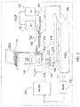
- FIG. 1 illustrates, schematically, a measurement system combining three sensors of the present invention in a pool treatment situation.
- water from a pool 100 is pumped via pump 102 through a filter 104 and then a flow sensor 106, to a chlorine sensor (i.e. measures free chlorine level, FCL) 108, a pH sensor 110, and an ORP sensor 112 of the present invention.
- the output from the sensors 106, 108, 110, and 112 are sent to a system control unit 114, also controlled by an external interface 116 (such as a mobile device or computer having a display), which can enter adjustments and desired settings, such as desired pH or chlorine content of the pool water, into the system control unit 114.
- an external interface 116 such as a mobile device or computer having a display
- the flow sensor 106 is used to compensate the signal on the chlorine sensor since the output of the chlorine sensor is proportional to the flowrate. This compensation is an important feature when using variable speed pumps.
- the system control unit 114 controls a sensor manifold 118 and control pumps (or valves) 120 and 122, which, according to instructions from system control unit 114 (and external interface 116), meter pH-adjusting chemicals and chlorine from supply tanks 124 and 126, respectively, into the water pumped from the pool, after which the water is recycled back into pool 100.
- a memory circuit such as an EEPROM placed inside the sensor housing.
- the memory circuit is used to store calibration and other information such as device identification (ID) and/or a serial number.
- ID device identification
- serial number a serial number
- Fig. 6 is a block diagram of sensors and a system control unit according to an embodiment of the invention.
- Fig. 6 illustrates a treatment system 600 for treating a liquid such as an aqueous liquid 602.
- a conduit 604 channels the aqueous liquid 602 to be treated.
- a treatment device 606 associated with the conduit alters the aqueous liquid 602 and has an input port 608 for receiving a treatment signal indicative of an extent to which the treatment device 606 alters the aqueous liquid 602.
- the treatment device 606 can be a chlorine pump 610A having a control input port 608A and/or an acid pump 610B having a control input port 608B.
- One or more sensors 612 sense a parameter of the aqueous liquid 602 and have an analog output port 614 providing analog signals indicative of the sensed parameters.
- the sensor 612 can be a chlorine sensor 616A, a pH sensor 616B, an ORP sensor 616C, and/or a TDS sensor 616D located within the conduit 604 (e.g., within a manifold).
- Each sensor has a calibration memory device 618 (e.g., an EEPROM or a tangible, non-transitory storage memory) storing digital information indicative of a calibration of the sensor 616 and has a digital output port 621 providing a digital signal indicative of the digital information.
- each sensor 612 senses a second parameter of the aqueous liquid 602 and provides a second analog signal via analog output port 614 indicative of second sensed parameter.
- the second parameter comprises temperature of the aqueous liquid 602 in which case the calibration memory device 618 (e.g., an EEPROM) stores digital information indicative of a temperature-compensated calibration of the sensor 616 and has a digital output port 621 providing a digital signal indicative of the digital information.
- the calibration memory device 618 is an integral part of the sensor 612 so that the calibration memory device 618 is embedded within the sensor 612 and enclosed by the sensor 612, such as illustrated in figs. 7-9 .
- the calibration memory device 618 and the sensor 612 comprise a unitary component within a housing.
- a system control unit i.e., controller 620
- the controller 620 has a digital input port 622 connected to the digital output port 621 of the sensor 616.
- the controller 620 receives the digital signal via its digital input port 622 and determines a calibration of the sensor 612.
- the controller 620 has an analog input port (e.g. an analog-to-digital (A/D) converter 624) connected to the analog output port 614 of the sensor 612.
- the controller 620 receives the analog signal via its analog input port and determines the parameter of the aqueous liquid based on the received analog signal and based on the received digital signal.
- the controller has an output port connected to the treatment device 606 providing the treatment signal to the input port of the treatment device.
- the treatment signal is configured to control the treatment device 606 as a function of the determined parameter by controlling the extent to which the treatment device alters the aqueous liquid 602.
- the treatment device 606 in one form comprises a chlorine supplier such as chlorine pump 610A or a chlorine generator for adding free chlorine to the aqueous liquid 602.
- the treatment signal is indicative of an amount of free chlorine added to the aqueous liquid or is indicative of a rate at which free chlorine is added to the aqueous liquid.
- the sensor comprises a chlorine sensor 616A sensing a free chlorine level of the aqueous liquid 602 and the analog signal is indicative of the free chlorine level of the aqueous liquid.
- the controller 620 determines the free chlorine level of the aqueous liquid 602 based on the received analog signal and based on the received digital signal.
- the treatment signal provided by the output port (e.g., a digital-to-analog (D/A) converter 626) of the controller is configured to control the chlorine supplier as a function of the determined free chlorine level of the aqueous liquid 602 as compared to a minimum free chlorine level by controlling the amount of free chlorine added to the aqueous liquid 602 by the chlorine supplier or the rate at which free chlorine is added to the aqueous liquid 602 by the chlorine supplier.
- D/A digital-to-analog
- the treatment device 606 comprises an acid supplier such as acid pump 610B for adding acid to the aqueous liquid.
- the treatment signal is indicative of an amount of acid added to the aqueous liquid or is indicative of a rate at which acid is added to the aqueous liquid.
- the sensor 612 comprises a pH sensor 616B sensing a pH level of the aqueous liquid and wherein the analog signal is indicative of the pH level of the aqueous liquid.
- the controller 620 determines the pH level of the aqueous liquid based on the received analog signal and based on the received digital signal.
- the treatment signal provided by the output port of the controller is configured to control the acid supplier as a function of the determined pH level of the aqueous liquid as compared to a maximum pH level by controlling the amount of acid added to the aqueous liquid by the acid supplier or the rate at which acid is added to the aqueous liquid by the acid supplier.
- the treatment device 606 comprises a chlorine supplier such as chlorine pump 610A for adding free chlorine to the aqueous liquid 602.
- the treatment signal is indicative of an amount of free chlorine added to the aqueous liquid 602 or is indicative of a rate at which free chlorine is added to the aqueous liquid 602.
- the sensor 612 comprises an ORP sensor 616 sensing a free chlorine level of the aqueous liquid 602.
- the analog signal is indicative of the free chlorine level of the aqueous liquid.
- the controller 620 determines the free chlorine level of the aqueous liquid 602 based on the received analog signal and based on the received digital signal.
- the treatment signal provided by the output port 626 of the controller is configured to control the chlorine supplier as a function of the determined free chlorine level of the aqueous liquid 602 as compared to a minimum free chlorine level by controlling the amount of chlorine added to the aqueous liquid by the chlorine supplier or the rate at which free chlorine is added to the aqueous liquid by the acid supplier.
- Each of the above sensors 612 includes a temperature sensing device 628 sensing a temperature of the aqueous liquid 602.
- the temperature sensing device 628 is illustrated separately in phantom in Fig. 6 .
- each of the chlorine sensor 616A, the pH sensor 616B, the ORP sensor 616C, and optionally the TDS sensor 616D each have a temperature sensing device such as a thermistor, as illustrated in Figs. 7-9 .
- the analog output port 614 provides a temperature signal indicative of the sensed temperature, although it is contemplated that the temperature sensing device can provide a digital signal via digital output port 621.
- the controller 620 receives the temperature signal via A/D converter 624.
- the controller 620 receives the temperature signal via digital input port 622.
- the controller 620 determines the temperature of the aqueous liquid 602 based on the temperature signal, and provides the treatment signal as a function of the determined temperature.
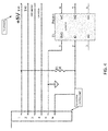
- the senor comprises a TDS sensor (see Fig. 3 ) sensing a TDS ppm salt level of the aqueous liquid 602.
- the analog signal 614 is indicative of the TDS ppm salt level of the aqueous liquid 602.
- the controller 602 determining the TDS ppm salt level of the aqueous liquid 602 based on the received analog signal and based on the received digital signal, the controller 602 provides an indication such as a notice on the external interface 116 and/or an alarm when the determined TDS ppm salt level of the aqueous liquid 602 is greater than a maximum.
- the calibration memory device comprises an EEPROM (e.g., DS2341) storing some or all of the following temperature compensation information (see Table 2 below): a high or low gain, an offset, and an analog-to-digital conversion value of the analog signal indicative of the sensed parameter.
- the solder pads are numbered the same as the connector for clarity.
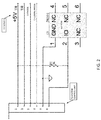
- Terminals 1 and 2 of the EEPROM DS2341 are connected to terminals 5 and 6 of the connector which is connected to the controller 620 providing and/or receiving the stored digital information.
- Terminal 1 is a ground port and terminal 2 is an input/output (I/O) port.
- each sensor 612 measures two parameters of a liquid such as an aqueous liquid and the calibration memory device stores information to calibrate one parameter relative to the other parameter.
- the EEPROM stores the following information: two or more temperature coefficients for adjusting the analog signal indicative of the sensed parameter
- the controller 620 includes a controller calibration memory device 634 in which the controller 620 reads the sensor calibration memory device 618 and stores the digital information stored in the calibration memory device 634 of the sensor 612.
- the controller can be configured to calibrate the sensor 612 in the event that the digital information stored in the calibration memory device 618 of the sensor is not valid, or the controller is configured with a memory device (not shown) having default calibration information in the event that the digital information stored in the calibration memory device 618 of the sensor 612 is not valid.
- the digital information stored in the calibration memory device 618 of the sensor 612 is encrypted and the controller 620 is configured to decrypt the encrypted digital information.
- the controller 620 stores a plurality of identification information identifying selected sensors 612.
- the controller 620 is configured to disable an operation of the system 600 if the calibration memory device 618 of the sensor 612 having its digital output port 614 connected to the digital input port 622 of the controller 620 does not have identification information which corresponds to (e.g. matches) the identification information stored in the controller memory device 634.
- identification information which corresponds to (e.g. matches) the identification information stored in the controller memory device 634.
- controller 620 is a microcontroller which communication to the memory 618 on each sensor 612 using a simple two wire connection on the sensor connector.
- a standard method based on the "1-Wire Protocol" such as implemented using a MAXIM DS2431 or similar circuitry can be used as the method of communication.
- the microprocessor detects when a sensor 612 is connected and retrieves the information from its EEPROM 618.
- Executable software stored in memory 636 prompts for overwrite then processes the input data and displays it on an LCD or other display device (such as a display of the external interface 116, not shown).
- Each circuit also has a communication port available to connect to an external interface 116 to read/write the EEPROM data for manual editing.
- the EEPROM data can be encrypted to prevent viewing/editing without authorization.
- the communication is through a "one wire" interface (such as IEEE P1451.4 Smart Sensor Interface) provided by a Dallas Semiconductor Corp DS2431 1-wire EEPROM.
- the interface uses a pull-up resistor from the I/O line of a microcontroller to both power the device and communicate with it. (See APPLICATION NOTE 2966 MINIMAL REMOTE 1-WIRE® MASTER Protocol from Maxim Integrated Circuits and DS2431 Datasheet.)
- Each sensor 612 can be assigned its own unalterable and unique 64-bit ROM registration number that is factory lasered into the chip. This gives every sensor 612 a unique identification number. In this case each sensor will have a unique "serial number”.
- Table 1 illustrates the various parameters detected by the sensors 612.
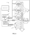
- Table 1 Sensor Analyte Desired Level Chemical Treatment Example(s) pH Fig. 5 Hydrogen ions
- the acid feed system is a 4:1 dilution of 20 degree Baume hydrochloric acid (31.45 wt.%) in water.
- the Hayward AQL-CHEM-2-240 is a CO 2 dispensing system. To lower pH, a manifold connects to a carbon dioxide tank. CO 2 reduces pH by forming carbonic acid (H 2 CO 3 ). Alternatively, the Sense and Dispense system supports the Stenner Pump acid feed system.
- the Baume scale measures the density of liquids heavier than water.
- the Baume of distilled water is 0.
- Hydrochloric acid is available in concentrations ranging from 4 to 23 degree Baume.
- AQL-CHEM-3-120 is an automatic acid dispensing system to lower the pH level of pool water. It utilizes a Stenner S1G45MJL3F2S/W2S series acid pump and 15 gallon tank.
- ORP Fig. 4 "Free chlorine"- a combination of hypochlorous acid (HOCl) and hypochlorite ion (OCl - ) providing a millivolt level primarily indicative of an oxidizing power of the water A voltage signal > 650 mV Generate "free chlorine" from NaCl.
- AQL-CHEM is a pH and ORP sensing kit which uses a chlorine generator to increase the level of free chlorine.
- a chlorine generator also known as a salt cell, salt generator, or salt chlorinator
- Chlorine Fig. 2 "Free chlorine"- a combination of hypochlorous acid (HOCl) and hypochlorite ion (OCl - ).
- the controller 620 If no sensor is connected, the controller 620 continually issues a reset signal (I/O Line low for 480 ⁇ s) and waits for the Presence signal consisting of the Slave pulling the line low within 60 ⁇ s from the time the controller 620 releases the line.
- a reset signal I/O Line low for 480 ⁇ s
- Presence signal consisting of the Slave pulling the line low within 60 ⁇ s from the time the controller 620 releases the line.
- the controller 620 senses the presence of a sensor 612, it goes through an ID process that reads the sensor file in memory 618 and makes sure that the correct sensor is attached.
- the controller 620 copies the calibration and ID information into its' own internal memory 634. It then prompts to overwrite the current calibration file.
- the software in memory 636 can notify a user if the sensor is different from the one it remembers. If there is not a valid calibration file in the sensor, the operator can be given two choices. Calibrate or Use raw ADC (default) values. If Calibration is chosen, the instrument will go into CALIBRATION MODE in which the sensor is recalibrated.
- Table 2 below indicates one embodiment for a table layout of calibration parameters and the number of bytes allocated for each for memory 618.
- Table 2 Description Type Size (Bytes) High Gain float 4 Offset float 4 ADC word 2 Temperature*10 word 2 Low Gain float 4 Offset float 4 ADC word 2 Temperature*10 word 2 Temp Comp coeff a float 4 coeff b float 4 coeff c float 4 Date Month byte 1 Day byte 1 Year-2000 byte 1 ID Sensor Type byte 1 Version word 2 Status byte 1 Checksum byte 1 Used 44 Available bytes 128 Free 84
- some or all of the information in memory 618 can be encrypted to prevent reverse engineering.
- the calibration information in the memory 618 is used to convert the ADC values from the sensor along with the current temperature to calculate the desired temperature-compensated output variable (e.g., Free Chlorine, TDS, pH, ORP).
- the desired temperature-compensated output variable e.g., Free Chlorine, TDS, pH, ORP.
- the calibration record of each sensor includes the signal level (in the units of the type of sensor) and the temperature at which it was measured at a high level of concentration and at a low level of concentration.
- Chlorine sensors are calibrated at a constant pH between 7.2 and 7.6.
- chlorine sensor 616A may be calibrated as follows.
- the sensor 616A is tested at a first known temperature and at a first known FCL level and the millivolt level at its analog output port 614A indicative of the chlorine level is read and saved.
- the thermistor 710 of the chlorine sensor 616A can be used to determine the first temperature.
- a sensor 616A at temperature 26.8°C and at an FCL level of 0.40 ppm provides a first 262.51 mV output.
- the sensor 616A is again tested at a second known temperature (which may be different from the first temperature) and at a second known FCL level (different from the first FCL level) and the millivolt level at its output 614A is read and saved.
- the same sensor 616A at temperature 26.2°C and at an FCL level of 3.40 ppm provides a second 481.07 mV output.
- the temperature readings can be determined by reading the thermistor 628 of the sensor 616A.
- the first and second readings are stored in the calibration memory 618A.
- the first known temperature, the first known FCL, and the resulting first mV output reading are entered into a table, as shown in Table 3 below.
- the second known temperature, the second known FCL, and the resulting second mV output reading are entered into the same table. Additional readings are extrapolated from the first and second readings and added to the table to provide a calibration table with automatic temperature compensation.
- This calibration table is used by the system control unit 620 to scale the mV readings and then derive the chlorine concentration from the chlorine sensor 616A.
- the first and second readings are used to define an algorithm which is then used to interpret readings from the chlorine sensor 616A.
- the table and/or algorithm can be stored in the calibration memory 618A and/or can be part of the system control unit 620.
- Table 3 Temp 1 26.8°C FCL 1 0.40 ppm mV 1 262.51 Temp 2 26.2°C FCL 2 3.40 ppm mV 2 481.07
- the system control unit 620 will divide the difference between the second known FCL level (3.40) and the first known FCL level (0.40) by the difference between the second known mV level (481.07) and the first known mV level (262.51).
- the system control unit 620 will use substitution to define b for the above formula by using the second known FCL level (3.40) as X, the second known mV level (481.07) as Y, and m as defined above.
- pH sensor 616B may be calibrated as follows.
- the sensor 616B is tested at a first known temperature and at a first known pH level and the millivolt level at its analog output port 614B indicative of the pH level is read and saved.
- the thermistor 710 of the pH sensor 616B can be used to determine the first temperature.
- a sensor 616B at temperature 26.8°C and at a pH level of 6.91 provides a first 2158.73 mV output.
- the sensor 616B is again tested at a second known temperature (which may be different from the first temperature) and at a second known pH level (different from the first pH level) and the millivolt level at its output 614B is read and saved.
- the same sensor 616B at temperature 26.2°C and at a pH level of 7.77 provides a second 2424.91 mV output.
- the temperature readings can be determined by reading the thermistor 628 of the sensor 616B.
- the first and second readings are stored in the calibration memory 618B.
- the first known temperature, the first known pH, and the resulting first mV output reading are entered into a table, as shown in Table 4 below.
- the second known temperature, the second known pH, and the resulting second mV output reading are entered into the same table. Additional readings are extrapolated from the first and second readings and added to the table to provide a calibration table with automatic temperature compensation.
- the calibration table is used by the system control unit 620 to scale the mV readings and then derive the pH level from the pH sensor 616B.
- the first and second readings are used to define an algorithm which is then used to interpret readings from the pH sensor 616B.
- the table and/or algorithm can be stored in the calibration memory 618B and/or can be part of the system control unit 620.
- Table 4 Temp 1 26.8°C pH 6.91 mV 1 2158.73 Temp 2 26.2°C pH 7.77 mV 2 2424.91
- the system control unit 620 will divide the difference between the second known pH level (7.77) and the first known pH level (6.91) by the difference between the second known mV level (2424.91) and the first known mV level (2158.73).
- the system control unit 620 will use substitution to define b for the above formula by using the second known pH level (7.77) as X, the second known mV level (2424.91) as Y, and m as defined above.
- ORP sensor 616C may be calibrated as follows. For ORP, a reference chlorine measurement is made and stored relative to a specific mV output from sensor 616C. Measurements are repeated at regular intervals (6 months or 1 time/season) to gauge sensor drift. There is no computational derivative of the values stored in sensor 616C.
- TDS sensor 616D may be calibrated as follows.
- the sensor 616D is tested at a first known temperature and at a first known pH level and the millivolt level at its analog output port 614D indicative of the TDS level is read and saved.
- the thermistor 710 of the TDS sensor 616D can be used to determine the first temperature.
- a sensor 616D at temperature 26.8°C and at a TDS level of 918 ppm provides a first 545.79 mV output.
- the sensor 616D is again tested at a second known temperature (which may be different from the first temperature) and at a second known TDS level (different from the first TDS level) and the millivolt level at its output 614D is read and saved.
- a second known temperature which may be different from the first temperature
- a second known TDS level different from the first TDS level
- the millivolt level at its output 614D is read and saved.
- the same sensor 616D at temperature 26.2°C and at a TDS level of 3430 ppm provides a second 1960.93 mV output.
- the temperature readings can be determined by reading the thermistor 628 of the sensor 616D.
- the first and second readings are stored in the calibration memory 618D.
- the first known temperature, the first known TDS, and the resulting first mV output reading are entered into a table, as shown in Table 5 below.
- the second known temperature, the second known TDS, and the resulting second mV output reading are entered into the same table. Additional readings are extrapolated from the first and second readings and added to the table to provide a calibration table with automatic temperature compensation is used by the system control unit 620 to scale the mV readings and then derive the TDS level from the TDS sensor 616D. Alternatively or in addition, the first and second readings are used to define an algorithm which is then used to interpret readings from the TDS sensor 616D.
- the table and/or algorithm can be stored in the calibration memory 618D and/or can be part of the system control unit 620. Table 5: Temp 1 26.8°C TDS 918 ppm mV 1 545.79 Temp 2 26.2°C TDS 3430 ppm mV 2 1960.93
- the system control unit 620 will divide the difference between the second known TDS level (3430ppm) and the first known TDS level (918ppm) by the difference between the second known mV level (1960.93) and the first known mV level (545.79).
- the system control unit 620 will use substitution to define b for the above formula by using the second known TDS level (3430ppm) as X, the second known mV level (1960.93) as Y, and m as defined above.
- the conductivity of the aqueous liquid is proportional to the conductivity so that an increase in current is indicative of an increase in total dissolved solids (TDS).
- ORP sensors are only checked for sufficient span using a quinhydrone solution mixed with two different pH buffers. Since ORP sensors do not necessarily need calibration, ORP sensor calibration memory 618C is optional. Even without calibration information, the ORP sensor calibration memory 618C is useful for providing identity and tracking information for each ORP sensor.
- the microprocessor of the controller 620 detects the presence of the sensor through the 1 wire interface. It then is queried for the calibration information which is compared to the calibration file held in its own internal flash memory. If it is the same no action is taken. If it is different, it prompts to overwrite the previous record.
- the sensor 612 can be configured for use with a Hayward Sense and Dispense system, which uses a salt chlorine supplier which generates chlorine by placing a DC current across two electrodes which separates the chlorine from the sodium chloride (NaCl).
- the chlorine supplier is controlled by the ORP sensor.
- the pH is controlled by monitoring the pH with a probe based on standard pH probe construction and actuating a valve on an acid tank to inject the proper amount of acid to maintain the pH at the desired level. Since the action of the chlorine supplier raises the pH over time, there is a need for addition of acid to keep the pH in bounds.
- the sensors 612 supplant sensors currently in use along with the attendant hardware and software to provide more accuracy and longevity.
- controller 620 stores a given amount of chemicals needed to change either the pH level or ORP level of the water to a desired level.
- Various automated chemical dispensing systems to adjust pH/ORP are provided, for example, by Hayward Industries Inc. (Elizabeth, New Jersey).
- Hayward Sense and Dispense® technology provides chemistry kits for sampling pH and free chlorine levels and adjusting chemical feeding.
- the Sense and Dispense® system uses a proportional feed algorithm that continuously tests the water, samples pH and sanitizing activity, and adjusts chemical feeding on a basis proportional to the demand.
- Sense and Dispense® consists of two kits.
- the first is AQL-CHEM, a pH and ORP sensing kit which uses a chlorine generator to increase the level of free chlorine.
- the chlorine generator also known as salt cell, salt generator, or salt chlorine supplier, uses electrolysis in the presence of dissolved salt (NaCl) to produce hypochlorous acid (HOCl) and sodium hypochlorite (NaOCl), which are the sanitizing agents commonly used in swimming pools.
- the adjustment of pH can be achieved using a second kit, AQL-CHEM2, which includes a manifold that connects to a carbon dioxide (CO 2 ) tank to inject carbon dioxide into the pool water.
- CO 2 carbon dioxide
- Carbon dioxide reduces pH to recommended levels by forming carbonic acid (H 2 CO 3 ), a weak acid that will lower the pH of the pool water slowly without the safety or health concerns normally associated with stronger acids.
- the Sense and Dispense® system also supports commercially available peristaltic acid pumps. With AQL-CHEM3, a Stenner Pump acid connected to a 15 gallon tank lowers the pool water pH by introduction of muriatic acid (aqueous hydrochloric acid).
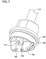
- Fig. 7 is a perspective view of a sensor according to one embodiment of the invention.
- Fig. 8 is cross-sectional view taken along lines 8-8 of Fig. 9.
- Fig. 9 is cross-sectional view taken along lines 9-9 of Fig. 7 .
- the sensor 612 includes an anode 702 sealed in a tube 703 comprising a proton exchange membrane such as a copolymer of tetrafluoroethylene (e.g., a NafionTM tube) and a cathode 704 spaced from the anode 702.
- a proton exchange membrane such as a copolymer of tetrafluoroethylene (e.g., a NafionTM tube)
- a cathode 704 spaced from the anode 702.
- the anode 702 and cathode 704 are supported by and wrapped over a wall 706 of an insulative housing 708 with sealing gasket 709 (e.g., an o-ring) which also supports a temperature sensing device such as a thermistor 710 having a resistance which varies with temperature.
- Thermistor electrodes TH1 and TH2 are connected to the thermistor 710 and to the system control unit 620 via a wire harness (not shown).
- the thermistor 710 has a small amount of current running through it, e.g., a bias current, which is sent by the system control unit 620.
- the system control unit 620 converts resistance changes to voltage changes by using a current source to apply a bias current across the thermistor to produce a control voltage. It is contemplated that thermistor 710 can be any temperature sensing device providing a signal indicative of the temperature of the device.
- a printed circuit board 712 has twelve plated through holes connected to a circuit printed on a surface of the board 712. Six plated through holes in the board 712 receive and electrically connect to one end of six wires 714; the other end of the wires connect to the electrical connector block of the circuits illustrated in Figs. 2-5 .
- the electrical connector block is connected to system control unit 114, 620 (shown in Figs. 1 and 6 ) by a wire harness (not shown). In Fig. 8 , only three wires 714A, 714B, 714C of the six wires 714 are illustrated.
- Two plated through holes in the board 712 receive and electrically connect to electrodes (not shown) of the calibration memory device 618 which is mounted on the board 712.
- Two plated through holes in the board 712 receive and electrically connect to the thermistor electrodes TH1 and TH2.
- Two plated through holes in the board 712 receive and electrically connect to the anode 702 and cathode 704.
- the six wires 714 are connected to the calibration memory device 618, the thermistor electrodes TH1, TH2, and to the anode 702 and cathode 704 via the circuit printed on the surface of the board 712.
- the senor 612 comprises a chlorine sensor comprising a gold cathode 704 and a platinum anode 702 sealed within a tube comprising a proton exchange membrane such as a copolymer of tetrafluoroethylene.
- the tube provides a barrier to oxygen and anions from the environment exterior to the tube except as may pass through the tube.
- a voltage source is configured for applying a bias voltage (e.g., 350 millivolts) between the anode and the cathode, wherein a positive voltage is applied to the anode and a negative voltage is applied to the cathode.
- the chlorine sensor output is a current signal which is indicative of the free chlorine in the aqueous liquid.
- the current signal is temperature dependent so that the EEPROM provides to the system control unit the necessary information to calibrate the current signal based on the temperature of the aqueous liquid.
- the senor 612 comprises a thermistor 720 and a pH sensor comprising: (i) a gel-filled reference electrode (e.g., anode 704); and (ii) a sensing electrode (e.g., cathode 702) of antimony/antimony oxide or bismuth/bismuth oxide having an electroactive surface sealed within a tube comprising a proton exchange membrane such as a copolymer of tetrafluoroethylene that provides a barrier for the sensing electrode to both oxygen and anions from the environment exterior to the tube.
- the pH sensor output is a current signal which is indicative of the pH of the aqueous liquid.
- the current signal is temperature dependent so that the EEPROM provides to the system control unit the necessary information to calibrate the current signal based on the temperature of the aqueous liquid.
- the senor 612 comprises a thermistor 720 and a halogen sensor such as a chlorine sensor comprising a metal anode 702 shielded by a low electrical resistance, water-permeable, oxygen barrier comprising a tube comprising a proton exchange membrane such as a copolymer of tetrafluoroethylene that provides a barrier for the sensing electrode to both oxygen and anions from the environment exterior to the tube.
- a voltage source is configured for applying a bias voltage (e.g., 350 millivolts) between the anode and the cathode, wherein a positive voltage is applied to the anode and a negative voltage is applied to the cathode.
- the halogen sensor output is a current signal which is indicative of the halogen in the aqueous liquid.
- the current signal is temperature dependent so that the EEPROM provides to the system control unit the necessary information to calibrate the current signal based on the temperature of the aqueous liquid.
- the senor 612 comprises a total dissolved solids (TDS) sensor comprising a pair of spaced-apart electrodes configured to be excited by a sine wave voltage of 16kHz at 1V AC excitation voltage.
- a current amplifier and rectifier electrically responsive to the pair of spaced-apart electrodes generate a voltage indicative of the voltage between the spaced-apart electrodes.
- a converter electrically responsive to the voltage indicative of the voltage between the spaced-apart electrodes converts the indicative voltage for at least one of display and processing.
- a display electrically responsive to the converter displays a total dissolved solids measurement in the aqueous solution in which the pair of spaced apart electrodes is placed.
- the TDS sensor output is a current signal which is indicative of the TDS of the aqueous liquid.
- the TDS of the aqueous liquid is proportional to its conductivity so that an increase in current is indicative of an increase in total dissolved solids (TDS).
- the current signal indicating TDS is generally insensitive to temperature for aqueous liquids so the EEPROM provides other information such as device identification (ID) and/or a serial number.
- ID device identification
- the TDS sensor can include a thermistor 710 and the EEPROM provides to the system control unit the necessary information to calibrate the current signal based on the temperature of the aqueous liquid.
- the senor 612 comprises an ORP sensor comprising a gold cathode 704 and a platinum anode 702 sealed within a tube comprising a proton exchange membrane such as a copolymer of tetrafluoroethylene.
- the tube provides a barrier to oxygen and anions from the environment exterior to the tube except as may pass through the tube.
- the ORP sensor output is a voltage signal which is indicative of the oxidizing power of the aqueous liquid.
- the voltage signal is temperature dependent so that the EEPROM provides to the system control unit the necessary information to calibrate the voltage signal based on the temperature of the aqueous liquid.
- the present invention comprises sensors 612, each of which is individually calibrated and has its own memory device 618 storing individualized calibration information which is unique to the individual device.
- each sensor 612 is calibrated at a production facility before the sensor 612 is installed within a system 600 so that the calibration information stored in memory device 618 is unique to the sensor 618 and independent of any system in which the sensor 618 is installed.
- each sensor 612 is calibrated by a reference system at a production facility before the sensor 612 is installed within a system 600 so that the calibrated sensors 618 are consistent with each other and the sensors 618 provide substantially the same output independent of the environment or system within which the sensors 618 are installed.
- programs and other executable program components such as the operating system
- programs and other executable program components are illustrated herein as discrete blocks. It is recognized, however, that such programs and components reside at various times in different storage components of a computing device, and are executed by a data processor(s) of the device.
- Examples of well-known computing systems, environments, and/or configurations that may be suitable for use with aspects of the invention include, but are not limited to, personal computers, server computers, hand-held or laptop devices, multiprocessor systems, microprocessor-based systems, set top boxes, programmable consumer electronics, mobile telephones, network PCs, minicomputers, mainframe computers, distributed computing environments that include any of the above systems or devices, and the like.
- Embodiments of the aspects of the invention may be described in the general context of data and/or processor-executable instructions, such as program modules, stored one or more tangible, non-transitory storage media and executed by one or more processors or other devices.
- program modules include, but are not limited to, routines, programs, objects, components, and data structures that perform particular tasks or implement particular abstract data types.
- aspects of the invention may also be practiced in distributed computing environments where tasks are performed by remote processing devices that are linked through a communications network.
- program modules may be located in both local and remote storage media including memory storage devices.
- processors, computers and/or servers may execute the processor-executable instructions (e.g., software, firmware, and/or hardware) such as those illustrated herein to implement aspects of the invention.
- processor-executable instructions e.g., software, firmware, and/or hardware
- Embodiments of the aspects of the invention may be implemented with processor-executable instructions.
- the processor-executable instructions may be organized into one or more processor-executable components or modules on a tangible processor readable storage medium which is not a signal.
- Aspects of the invention may be implemented with any number and organization of such components or modules. For example, aspects of the invention are not limited to the specific processor-executable instructions or the specific components or modules illustrated in the figures and described herein. Other embodiments of the aspects of the invention may include different processor-executable instructions or components having more or less functionality than illustrated and described herein.
Landscapes
- Chemical & Material Sciences (AREA)
- Life Sciences & Earth Sciences (AREA)
- Health & Medical Sciences (AREA)
- General Physics & Mathematics (AREA)
- Pathology (AREA)
- Electrochemistry (AREA)
- Physics & Mathematics (AREA)
- Analytical Chemistry (AREA)
- Biochemistry (AREA)
- General Health & Medical Sciences (AREA)
- Molecular Biology (AREA)
- Immunology (AREA)
- Chemical Kinetics & Catalysis (AREA)
- Hydrology & Water Resources (AREA)
- Engineering & Computer Science (AREA)
- Environmental & Geological Engineering (AREA)
- Water Supply & Treatment (AREA)
- Organic Chemistry (AREA)
- Investigating Or Analyzing Materials By The Use Of Electric Means (AREA)
- Water Treatment By Electricity Or Magnetism (AREA)
- Investigating Or Analysing Materials By The Use Of Chemical Reactions (AREA)
- Treatment Of Water By Oxidation Or Reduction (AREA)
Applications Claiming Priority (1)
| Application Number | Priority Date | Filing Date | Title |
|---|---|---|---|
| US201562144439P | 2015-04-08 | 2015-04-08 |
Publications (2)
| Publication Number | Publication Date |
|---|---|
| EP3109629A2 true EP3109629A2 (fr) | 2016-12-28 |
| EP3109629A3 EP3109629A3 (fr) | 2017-03-22 |
Family
ID=56092710
Family Applications (1)
| Application Number | Title | Priority Date | Filing Date |
|---|---|---|---|
| EP16164301.0A Withdrawn EP3109629A3 (fr) | 2015-04-08 | 2016-04-07 | Capteur avec mémoire stockant des informations d'étalonnage |
Country Status (2)
| Country | Link |
|---|---|
| US (3) | US10329177B2 (fr) |
| EP (1) | EP3109629A3 (fr) |
Cited By (2)
| Publication number | Priority date | Publication date | Assignee | Title |
|---|---|---|---|---|
| DE102017103684A1 (de) | 2017-02-23 | 2018-08-23 | Endress+Hauser Conducta Gmbh+Co. Kg | Messeinrichtung zur messtechnischen Erfassung einer Konzentration eines in einem Fluid enthaltenen Analyten |
| WO2019005609A1 (fr) * | 2017-06-30 | 2019-01-03 | Arch Chemicals, Inc. | Systèmes et procédés pour la prévention et l'élimination du tartre dans des systèmes de désinfection |
Families Citing this family (18)
| Publication number | Priority date | Publication date | Assignee | Title |
|---|---|---|---|---|
| US10900921B2 (en) | 2015-01-20 | 2021-01-26 | Masco Corporation | Multi-functional water quality sensor |
| US12012344B2 (en) * | 2015-08-28 | 2024-06-18 | Bryan R. Johnson | Integrated biogas treatment and carbon dioxide based disinfection for water treatment |
| US12528726B2 (en) | 2015-08-28 | 2026-01-20 | Energy Tech Innovations, LLC | Method and apparatus for treating biogas |
| JP6856867B2 (ja) * | 2017-01-31 | 2021-04-14 | 東亜ディーケーケー株式会社 | 無試薬式遊離残留塩素測定装置および無試薬式遊離残留塩素測定方法 |
| EP3379239A1 (fr) * | 2017-03-22 | 2018-09-26 | Yokogawa Process Analyzers Europe B.V. | Capteur et partie de traitement d'un capteur |
| US12163944B2 (en) | 2017-07-20 | 2024-12-10 | The Regents Of The University Of Michigan | Multi-functional water quality sensor |
| EP3511299A1 (fr) * | 2018-01-15 | 2019-07-17 | Danish Clean Water A/S | Surveillance redondante d'un système de stérilisation d'eau |
| JP7093005B2 (ja) * | 2018-06-29 | 2022-06-29 | 東亜ディーケーケー株式会社 | 無試薬式全有効塩素測定装置とその校正方法および無試薬式全有効塩素測定方法 |
| EP3643684A1 (fr) * | 2018-10-22 | 2020-04-29 | Geodesic Innovations, S.L. | Système et procédure pour la désinfection et la conservation d'eau dans des circuits avec accumulation d'eau au moyen d'appliquer une électroporation et une oxydation combinées |
| CN110261438B (zh) * | 2019-07-15 | 2023-12-26 | 张家港万众一芯生物科技有限公司 | 水管式在线水质检测装置 |
| AU2020345904A1 (en) * | 2019-09-11 | 2022-04-28 | Hayward Industries, Inc. | Swimming pool pressure and flow control pumping and water distribution systems and methods |
| CN111077280B (zh) * | 2020-01-14 | 2020-08-25 | 浙江清华长三角研究院 | 一种基于河网的农村污水处理设施与水质监测站点间的溯源分析方法 |
| FR3126411A1 (fr) * | 2021-09-01 | 2023-03-03 | Yneom | Dispositif de traitement de l’eau pour une piscine |
| US12486156B2 (en) * | 2022-08-16 | 2025-12-02 | Generosity Water, Inc. | Alkaline water dispensing apparatus with water consumption tracking functionality |
| US12583773B2 (en) * | 2023-01-27 | 2026-03-24 | Swim Sense Llc | Acid-dispensing system for pools |
| CN117783442B (zh) * | 2023-12-31 | 2025-11-25 | 无锡英凡特科技有限公司 | 一种高速氯气探测器 |
| US20250223205A1 (en) * | 2024-01-05 | 2025-07-10 | Ecolab Usa Inc. | Method and device for monitoring chlorine in a pool |
| WO2026013673A1 (fr) * | 2024-07-09 | 2026-01-15 | Maytronics Ltd. | Estimation de potentiel de réduction d'oxydation dans des masse d'eau |
Family Cites Families (15)
| Publication number | Priority date | Publication date | Assignee | Title |
|---|---|---|---|---|
| CA1316572C (fr) | 1988-07-18 | 1993-04-20 | Martin J. Patko | Senseur electrochimique, jetable, pre-etalonne |
| EP0870176B1 (fr) | 1995-12-22 | 2003-03-19 | Brüel & Kjaer Sound & Vibration Measurement A/S | Systeme et procede de mesure d'un signal continu |
| US6270680B1 (en) * | 1997-11-07 | 2001-08-07 | Bioquest | Amperometric sensor probe for an automatic halogen control system |
| US6125481A (en) * | 1999-03-11 | 2000-10-03 | Sicilano; Edward N. | Swimming pool management system |
| ATE356973T1 (de) | 2001-10-12 | 2007-04-15 | Kistler Holding Ag | Sensor |
| US7638042B2 (en) * | 2002-02-15 | 2009-12-29 | 3M Innovative Properties Company | System for monitoring the performance of fluid treatment cartridges |
| US20040124253A1 (en) * | 2002-10-17 | 2004-07-01 | Bergwin Gregory A. | Injection apparatus for irrigation system |
| US7632410B2 (en) * | 2003-08-21 | 2009-12-15 | Christopher Heiss | Universal water purification system |
| US20060106561A1 (en) | 2004-11-12 | 2006-05-18 | Michelin Recherche Et Technique S.A. | Centralized calibration coefficients for sensor based measurements |
| US7664607B2 (en) | 2005-10-04 | 2010-02-16 | Teledyne Technologies Incorporated | Pre-calibrated gas sensor |
| US7857506B2 (en) | 2005-12-05 | 2010-12-28 | Sencal Llc | Disposable, pre-calibrated, pre-validated sensors for use in bio-processing applications |
| US7551275B2 (en) | 2007-06-29 | 2009-06-23 | Xerox Corporation | Sensor calibration system and method |
| US8324824B2 (en) | 2009-01-29 | 2012-12-04 | Ixys Corporation | 1-wire communication protocol and interface circuit |
| US8513956B2 (en) * | 2010-07-26 | 2013-08-20 | Mettler-Toledo Thornton, Inc. | Calibration of conductivity measurement system |
| US8574413B2 (en) | 2011-03-18 | 2013-11-05 | Digital Concepts Of Missouri, Inc. | Electrodes, sensors and methods for measuring components in water |
-
2016
- 2016-04-06 US US15/091,679 patent/US10329177B2/en active Active
- 2016-04-07 EP EP16164301.0A patent/EP3109629A3/fr not_active Withdrawn
-
2019
- 2019-06-24 US US16/450,249 patent/US11078096B2/en active Active
-
2021
- 2021-08-02 US US17/391,696 patent/US11840465B2/en active Active
Non-Patent Citations (1)
| Title |
|---|
| None |
Cited By (2)
| Publication number | Priority date | Publication date | Assignee | Title |
|---|---|---|---|---|
| DE102017103684A1 (de) | 2017-02-23 | 2018-08-23 | Endress+Hauser Conducta Gmbh+Co. Kg | Messeinrichtung zur messtechnischen Erfassung einer Konzentration eines in einem Fluid enthaltenen Analyten |
| WO2019005609A1 (fr) * | 2017-06-30 | 2019-01-03 | Arch Chemicals, Inc. | Systèmes et procédés pour la prévention et l'élimination du tartre dans des systèmes de désinfection |
Also Published As
| Publication number | Publication date |
|---|---|
| EP3109629A3 (fr) | 2017-03-22 |
| US11840465B2 (en) | 2023-12-12 |
| US11078096B2 (en) | 2021-08-03 |
| US20160299096A1 (en) | 2016-10-13 |
| US10329177B2 (en) | 2019-06-25 |
| US20210355005A1 (en) | 2021-11-18 |
| US20190322556A1 (en) | 2019-10-24 |
Similar Documents
| Publication | Publication Date | Title |
|---|---|---|
| US11840465B2 (en) | Sensor with memory storing calibration information | |
| EP3870965B1 (fr) | Systèmes et procédés de détection et de mesure de composés oxydants dans des fluides d'essai | |
| US8574413B2 (en) | Electrodes, sensors and methods for measuring components in water | |
| US10481117B2 (en) | Amperometric sensor system | |
| CN107003280B (zh) | 电流型氯传感器 | |
| AU2018204817A1 (en) | Multi-functional water quality sensor | |
| US20040211731A1 (en) | Method for monitoring and controlling chlorine levels in an aqueous medium | |
| JP2018103167A (ja) | 殺菌水の供給方法および供給装置 | |
| WO1998058136A1 (fr) | Procede de regulation de la quantite d'agent de nettoyage dans un milieu aqueux | |
| US6054030A (en) | System for monitoring biocide treatments | |
| JP4714209B2 (ja) | Cod自動計測器およびそれを用いたcodの測定方法 | |
| Gouws et al. | Design and cost analysis of an automation system for swimming pools in South Africa | |
| TWI817443B (zh) | 水處理應用中可變組成之水性鹵素的響應式製備及輸送 | |
| KR100366954B1 (ko) | 염소 자동공급장치 | |
| US12522525B1 (en) | Chemical maintenance systems | |
| JPH06249832A (ja) | 亜塩素酸イオンの測定方法 | |
| JPH07190989A (ja) | 電解水流通特性検知装置 | |
| JP3196387B2 (ja) | 金属酸化物pH電極による電解酸性水のpH測定方法 | |
| Kim et al. | Effectiveness of the electrochemical sensor for the free chlorine measurement | |
| JPS6018752A (ja) | 残留塩素測定装置 | |
| JPS6018753A (ja) | 残留塩素測定装置 |
Legal Events
| Date | Code | Title | Description |
|---|---|---|---|
| PUAI | Public reference made under article 153(3) epc to a published international application that has entered the european phase |
Free format text: ORIGINAL CODE: 0009012 |
|
| AK | Designated contracting states |
Kind code of ref document: A2 Designated state(s): AL AT BE BG CH CY CZ DE DK EE ES FI FR GB GR HR HU IE IS IT LI LT LU LV MC MK MT NL NO PL PT RO RS SE SI SK SM TR |
|
| AX | Request for extension of the european patent |
Extension state: BA ME |
|
| PUAL | Search report despatched |
Free format text: ORIGINAL CODE: 0009013 |
|
| AK | Designated contracting states |
Kind code of ref document: A3 Designated state(s): AL AT BE BG CH CY CZ DE DK EE ES FI FR GB GR HR HU IE IS IT LI LT LU LV MC MK MT NL NO PL PT RO RS SE SI SK SM TR |
|
| AX | Request for extension of the european patent |
Extension state: BA ME |
|
| RIC1 | Information provided on ipc code assigned before grant |
Ipc: C02F 1/66 20060101ALI20170214BHEP Ipc: G01N 27/416 20060101AFI20170214BHEP Ipc: C02F 1/76 20060101ALI20170214BHEP Ipc: G01N 33/18 20060101ALN20170214BHEP |
|
| 17P | Request for examination filed |
Effective date: 20170919 |
|
| RBV | Designated contracting states (corrected) |
Designated state(s): AL AT BE BG CH CY CZ DE DK EE ES FI FR GB GR HR HU IE IS IT LI LT LU LV MC MK MT NL NO PL PT RO RS SE SI SK SM TR |
|
| STAA | Information on the status of an ep patent application or granted ep patent |
Free format text: STATUS: THE APPLICATION HAS BEEN WITHDRAWN |
|
| 18W | Application withdrawn |
Effective date: 20190129 |