EP3110468B1 - Ventrikuläre hilfsvorrichtung und verfahren - Google Patents
Ventrikuläre hilfsvorrichtung und verfahren Download PDFInfo
- Publication number
- EP3110468B1 EP3110468B1 EP15755879.2A EP15755879A EP3110468B1 EP 3110468 B1 EP3110468 B1 EP 3110468B1 EP 15755879 A EP15755879 A EP 15755879A EP 3110468 B1 EP3110468 B1 EP 3110468B1
- Authority
- EP
- European Patent Office
- Prior art keywords
- rotor
- stator
- magnets
- bearing
- flow housing
- Prior art date
- Legal status (The legal status is an assumption and is not a legal conclusion. Google has not performed a legal analysis and makes no representation as to the accuracy of the status listed.)
- Active
Links
Images









Classifications
-
- A—HUMAN NECESSITIES
- A61—MEDICAL OR VETERINARY SCIENCE; HYGIENE
- A61F—FILTERS IMPLANTABLE INTO BLOOD VESSELS; PROSTHESES; DEVICES PROVIDING PATENCY TO, OR PREVENTING COLLAPSING OF, TUBULAR STRUCTURES OF THE BODY, e.g. STENTS; ORTHOPAEDIC, NURSING OR CONTRACEPTIVE DEVICES; FOMENTATION; TREATMENT OR PROTECTION OF EYES OR EARS; BANDAGES, DRESSINGS OR ABSORBENT PADS; FIRST-AID KITS
- A61F2/00—Filters implantable into blood vessels; Prostheses, i.e. artificial substitutes or replacements for parts of the body; Appliances for connecting them with the body; Devices providing patency to, or preventing collapsing of, tubular structures of the body, e.g. stents
- A61F2/82—Devices providing patency to, or preventing collapsing of, tubular structures of the body, e.g. stents
-
- A—HUMAN NECESSITIES
- A61—MEDICAL OR VETERINARY SCIENCE; HYGIENE
- A61F—FILTERS IMPLANTABLE INTO BLOOD VESSELS; PROSTHESES; DEVICES PROVIDING PATENCY TO, OR PREVENTING COLLAPSING OF, TUBULAR STRUCTURES OF THE BODY, e.g. STENTS; ORTHOPAEDIC, NURSING OR CONTRACEPTIVE DEVICES; FOMENTATION; TREATMENT OR PROTECTION OF EYES OR EARS; BANDAGES, DRESSINGS OR ABSORBENT PADS; FIRST-AID KITS
- A61F2/00—Filters implantable into blood vessels; Prostheses, i.e. artificial substitutes or replacements for parts of the body; Appliances for connecting them with the body; Devices providing patency to, or preventing collapsing of, tubular structures of the body, e.g. stents
- A61F2/02—Prostheses implantable into the body
- A61F2/04—Hollow or tubular parts of organs, e.g. bladders, tracheae, bronchi or bile ducts
- A61F2/06—Blood vessels
- A61F2/07—Stent-grafts
-
- A—HUMAN NECESSITIES
- A61—MEDICAL OR VETERINARY SCIENCE; HYGIENE
- A61F—FILTERS IMPLANTABLE INTO BLOOD VESSELS; PROSTHESES; DEVICES PROVIDING PATENCY TO, OR PREVENTING COLLAPSING OF, TUBULAR STRUCTURES OF THE BODY, e.g. STENTS; ORTHOPAEDIC, NURSING OR CONTRACEPTIVE DEVICES; FOMENTATION; TREATMENT OR PROTECTION OF EYES OR EARS; BANDAGES, DRESSINGS OR ABSORBENT PADS; FIRST-AID KITS
- A61F2/00—Filters implantable into blood vessels; Prostheses, i.e. artificial substitutes or replacements for parts of the body; Appliances for connecting them with the body; Devices providing patency to, or preventing collapsing of, tubular structures of the body, e.g. stents
- A61F2/82—Devices providing patency to, or preventing collapsing of, tubular structures of the body, e.g. stents
- A61F2/86—Stents in a form characterised by the wire-like elements; Stents in the form characterised by a net-like or mesh-like structure
- A61F2/90—Stents in a form characterised by the wire-like elements; Stents in the form characterised by a net-like or mesh-like structure characterised by a net-like or mesh-like structure
-
- A—HUMAN NECESSITIES
- A61—MEDICAL OR VETERINARY SCIENCE; HYGIENE
- A61F—FILTERS IMPLANTABLE INTO BLOOD VESSELS; PROSTHESES; DEVICES PROVIDING PATENCY TO, OR PREVENTING COLLAPSING OF, TUBULAR STRUCTURES OF THE BODY, e.g. STENTS; ORTHOPAEDIC, NURSING OR CONTRACEPTIVE DEVICES; FOMENTATION; TREATMENT OR PROTECTION OF EYES OR EARS; BANDAGES, DRESSINGS OR ABSORBENT PADS; FIRST-AID KITS
- A61F2/00—Filters implantable into blood vessels; Prostheses, i.e. artificial substitutes or replacements for parts of the body; Appliances for connecting them with the body; Devices providing patency to, or preventing collapsing of, tubular structures of the body, e.g. stents
- A61F2/95—Instruments specially adapted for placement or removal of stents or stent-grafts
-
- A—HUMAN NECESSITIES
- A61—MEDICAL OR VETERINARY SCIENCE; HYGIENE
- A61M—DEVICES FOR INTRODUCING MEDIA INTO, OR ONTO, THE BODY; DEVICES FOR TRANSDUCING BODY MEDIA OR FOR TAKING MEDIA FROM THE BODY; DEVICES FOR PRODUCING OR ENDING SLEEP OR STUPOR
- A61M60/00—Blood pumps; Devices for mechanical circulatory actuation; Balloon pumps for circulatory assistance
- A61M60/10—Location thereof with respect to the patient's body
- A61M60/122—Implantable pumps or pumping devices, i.e. the blood being pumped inside the patient's body
- A61M60/126—Implantable pumps or pumping devices, i.e. the blood being pumped inside the patient's body implantable via, into, inside, in line, branching on, or around a blood vessel
- A61M60/135—Implantable pumps or pumping devices, i.e. the blood being pumped inside the patient's body implantable via, into, inside, in line, branching on, or around a blood vessel inside a blood vessel, e.g. using grafting
- A61M60/139—Implantable pumps or pumping devices, i.e. the blood being pumped inside the patient's body implantable via, into, inside, in line, branching on, or around a blood vessel inside a blood vessel, e.g. using grafting inside the aorta, e.g. intra-aortic balloon pumps
-
- A—HUMAN NECESSITIES
- A61—MEDICAL OR VETERINARY SCIENCE; HYGIENE
- A61M—DEVICES FOR INTRODUCING MEDIA INTO, OR ONTO, THE BODY; DEVICES FOR TRANSDUCING BODY MEDIA OR FOR TAKING MEDIA FROM THE BODY; DEVICES FOR PRODUCING OR ENDING SLEEP OR STUPOR
- A61M60/00—Blood pumps; Devices for mechanical circulatory actuation; Balloon pumps for circulatory assistance
- A61M60/10—Location thereof with respect to the patient's body
- A61M60/122—Implantable pumps or pumping devices, i.e. the blood being pumped inside the patient's body
- A61M60/126—Implantable pumps or pumping devices, i.e. the blood being pumped inside the patient's body implantable via, into, inside, in line, branching on, or around a blood vessel
- A61M60/148—Implantable pumps or pumping devices, i.e. the blood being pumped inside the patient's body implantable via, into, inside, in line, branching on, or around a blood vessel in line with a blood vessel using resection or like techniques, e.g. permanent endovascular heart assist devices
-
- A—HUMAN NECESSITIES
- A61—MEDICAL OR VETERINARY SCIENCE; HYGIENE
- A61M—DEVICES FOR INTRODUCING MEDIA INTO, OR ONTO, THE BODY; DEVICES FOR TRANSDUCING BODY MEDIA OR FOR TAKING MEDIA FROM THE BODY; DEVICES FOR PRODUCING OR ENDING SLEEP OR STUPOR
- A61M60/00—Blood pumps; Devices for mechanical circulatory actuation; Balloon pumps for circulatory assistance
- A61M60/10—Location thereof with respect to the patient's body
- A61M60/122—Implantable pumps or pumping devices, i.e. the blood being pumped inside the patient's body
- A61M60/165—Implantable pumps or pumping devices, i.e. the blood being pumped inside the patient's body implantable in, on, or around the heart
- A61M60/178—Implantable pumps or pumping devices, i.e. the blood being pumped inside the patient's body implantable in, on, or around the heart drawing blood from a ventricle and returning the blood to the arterial system via a cannula external to the ventricle, e.g. left or right ventricular assist devices
-
- A—HUMAN NECESSITIES
- A61—MEDICAL OR VETERINARY SCIENCE; HYGIENE
- A61M—DEVICES FOR INTRODUCING MEDIA INTO, OR ONTO, THE BODY; DEVICES FOR TRANSDUCING BODY MEDIA OR FOR TAKING MEDIA FROM THE BODY; DEVICES FOR PRODUCING OR ENDING SLEEP OR STUPOR
- A61M60/00—Blood pumps; Devices for mechanical circulatory actuation; Balloon pumps for circulatory assistance
- A61M60/20—Type thereof
- A61M60/205—Non-positive displacement blood pumps
- A61M60/216—Non-positive displacement blood pumps including a rotating member acting on the blood, e.g. impeller
-
- A—HUMAN NECESSITIES
- A61—MEDICAL OR VETERINARY SCIENCE; HYGIENE
- A61M—DEVICES FOR INTRODUCING MEDIA INTO, OR ONTO, THE BODY; DEVICES FOR TRANSDUCING BODY MEDIA OR FOR TAKING MEDIA FROM THE BODY; DEVICES FOR PRODUCING OR ENDING SLEEP OR STUPOR
- A61M60/00—Blood pumps; Devices for mechanical circulatory actuation; Balloon pumps for circulatory assistance
- A61M60/20—Type thereof
- A61M60/205—Non-positive displacement blood pumps
- A61M60/216—Non-positive displacement blood pumps including a rotating member acting on the blood, e.g. impeller
- A61M60/237—Non-positive displacement blood pumps including a rotating member acting on the blood, e.g. impeller the blood flow through the rotating member having mainly axial components, e.g. axial flow pumps
-
- A—HUMAN NECESSITIES
- A61—MEDICAL OR VETERINARY SCIENCE; HYGIENE
- A61M—DEVICES FOR INTRODUCING MEDIA INTO, OR ONTO, THE BODY; DEVICES FOR TRANSDUCING BODY MEDIA OR FOR TAKING MEDIA FROM THE BODY; DEVICES FOR PRODUCING OR ENDING SLEEP OR STUPOR
- A61M60/00—Blood pumps; Devices for mechanical circulatory actuation; Balloon pumps for circulatory assistance
- A61M60/40—Details relating to driving
- A61M60/403—Details relating to driving for non-positive displacement blood pumps
- A61M60/419—Details relating to driving for non-positive displacement blood pumps the force acting on the blood contacting member being permanent magnetic, e.g. from a rotating magnetic coupling between driving and driven magnets
-
- A—HUMAN NECESSITIES
- A61—MEDICAL OR VETERINARY SCIENCE; HYGIENE
- A61M—DEVICES FOR INTRODUCING MEDIA INTO, OR ONTO, THE BODY; DEVICES FOR TRANSDUCING BODY MEDIA OR FOR TAKING MEDIA FROM THE BODY; DEVICES FOR PRODUCING OR ENDING SLEEP OR STUPOR
- A61M60/00—Blood pumps; Devices for mechanical circulatory actuation; Balloon pumps for circulatory assistance
- A61M60/40—Details relating to driving
- A61M60/403—Details relating to driving for non-positive displacement blood pumps
- A61M60/422—Details relating to driving for non-positive displacement blood pumps the force acting on the blood contacting member being electromagnetic, e.g. using canned motor pumps
-
- A—HUMAN NECESSITIES
- A61—MEDICAL OR VETERINARY SCIENCE; HYGIENE
- A61M—DEVICES FOR INTRODUCING MEDIA INTO, OR ONTO, THE BODY; DEVICES FOR TRANSDUCING BODY MEDIA OR FOR TAKING MEDIA FROM THE BODY; DEVICES FOR PRODUCING OR ENDING SLEEP OR STUPOR
- A61M60/00—Blood pumps; Devices for mechanical circulatory actuation; Balloon pumps for circulatory assistance
- A61M60/50—Details relating to control
- A61M60/508—Electronic control means, e.g. for feedback regulation
- A61M60/515—Regulation using real-time patient data
-
- A—HUMAN NECESSITIES
- A61—MEDICAL OR VETERINARY SCIENCE; HYGIENE
- A61M—DEVICES FOR INTRODUCING MEDIA INTO, OR ONTO, THE BODY; DEVICES FOR TRANSDUCING BODY MEDIA OR FOR TAKING MEDIA FROM THE BODY; DEVICES FOR PRODUCING OR ENDING SLEEP OR STUPOR
- A61M60/00—Blood pumps; Devices for mechanical circulatory actuation; Balloon pumps for circulatory assistance
- A61M60/50—Details relating to control
- A61M60/508—Electronic control means, e.g. for feedback regulation
- A61M60/538—Regulation using real-time blood pump operational parameter data, e.g. motor current
-
- A—HUMAN NECESSITIES
- A61—MEDICAL OR VETERINARY SCIENCE; HYGIENE
- A61M—DEVICES FOR INTRODUCING MEDIA INTO, OR ONTO, THE BODY; DEVICES FOR TRANSDUCING BODY MEDIA OR FOR TAKING MEDIA FROM THE BODY; DEVICES FOR PRODUCING OR ENDING SLEEP OR STUPOR
- A61M60/00—Blood pumps; Devices for mechanical circulatory actuation; Balloon pumps for circulatory assistance
- A61M60/50—Details relating to control
- A61M60/508—Electronic control means, e.g. for feedback regulation
- A61M60/562—Electronic control means, e.g. for feedback regulation for making blood flow pulsatile in blood pumps that do not intrinsically create pulsatile flow
-
- A—HUMAN NECESSITIES
- A61—MEDICAL OR VETERINARY SCIENCE; HYGIENE
- A61M—DEVICES FOR INTRODUCING MEDIA INTO, OR ONTO, THE BODY; DEVICES FOR TRANSDUCING BODY MEDIA OR FOR TAKING MEDIA FROM THE BODY; DEVICES FOR PRODUCING OR ENDING SLEEP OR STUPOR
- A61M60/00—Blood pumps; Devices for mechanical circulatory actuation; Balloon pumps for circulatory assistance
- A61M60/80—Constructional details other than related to driving
- A61M60/802—Constructional details other than related to driving of non-positive displacement blood pumps
- A61M60/818—Bearings
- A61M60/82—Magnetic bearings
-
- A—HUMAN NECESSITIES
- A61—MEDICAL OR VETERINARY SCIENCE; HYGIENE
- A61M—DEVICES FOR INTRODUCING MEDIA INTO, OR ONTO, THE BODY; DEVICES FOR TRANSDUCING BODY MEDIA OR FOR TAKING MEDIA FROM THE BODY; DEVICES FOR PRODUCING OR ENDING SLEEP OR STUPOR
- A61M60/00—Blood pumps; Devices for mechanical circulatory actuation; Balloon pumps for circulatory assistance
- A61M60/80—Constructional details other than related to driving
- A61M60/802—Constructional details other than related to driving of non-positive displacement blood pumps
- A61M60/818—Bearings
- A61M60/824—Hydrodynamic or fluid film bearings
-
- A—HUMAN NECESSITIES
- A61—MEDICAL OR VETERINARY SCIENCE; HYGIENE
- A61M—DEVICES FOR INTRODUCING MEDIA INTO, OR ONTO, THE BODY; DEVICES FOR TRANSDUCING BODY MEDIA OR FOR TAKING MEDIA FROM THE BODY; DEVICES FOR PRODUCING OR ENDING SLEEP OR STUPOR
- A61M60/00—Blood pumps; Devices for mechanical circulatory actuation; Balloon pumps for circulatory assistance
- A61M60/80—Constructional details other than related to driving
- A61M60/855—Constructional details other than related to driving of implantable pumps or pumping devices
- A61M60/871—Energy supply devices; Converters therefor
- A61M60/873—Energy supply devices; Converters therefor specially adapted for wireless or transcutaneous energy transfer [TET], e.g. inductive charging
-
- A—HUMAN NECESSITIES
- A61—MEDICAL OR VETERINARY SCIENCE; HYGIENE
- A61F—FILTERS IMPLANTABLE INTO BLOOD VESSELS; PROSTHESES; DEVICES PROVIDING PATENCY TO, OR PREVENTING COLLAPSING OF, TUBULAR STRUCTURES OF THE BODY, e.g. STENTS; ORTHOPAEDIC, NURSING OR CONTRACEPTIVE DEVICES; FOMENTATION; TREATMENT OR PROTECTION OF EYES OR EARS; BANDAGES, DRESSINGS OR ABSORBENT PADS; FIRST-AID KITS
- A61F2/00—Filters implantable into blood vessels; Prostheses, i.e. artificial substitutes or replacements for parts of the body; Appliances for connecting them with the body; Devices providing patency to, or preventing collapsing of, tubular structures of the body, e.g. stents
- A61F2/02—Prostheses implantable into the body
- A61F2/04—Hollow or tubular parts of organs, e.g. bladders, tracheae, bronchi or bile ducts
- A61F2/06—Blood vessels
- A61F2002/068—Modifying the blood flow model, e.g. by diffuser or deflector
-
- A—HUMAN NECESSITIES
- A61—MEDICAL OR VETERINARY SCIENCE; HYGIENE
- A61F—FILTERS IMPLANTABLE INTO BLOOD VESSELS; PROSTHESES; DEVICES PROVIDING PATENCY TO, OR PREVENTING COLLAPSING OF, TUBULAR STRUCTURES OF THE BODY, e.g. STENTS; ORTHOPAEDIC, NURSING OR CONTRACEPTIVE DEVICES; FOMENTATION; TREATMENT OR PROTECTION OF EYES OR EARS; BANDAGES, DRESSINGS OR ABSORBENT PADS; FIRST-AID KITS
- A61F2210/00—Particular material properties of prostheses classified in groups A61F2/00 - A61F2/26 or A61F2/82 or A61F9/00 or A61F11/00 or subgroups thereof
- A61F2210/009—Particular material properties of prostheses classified in groups A61F2/00 - A61F2/26 or A61F2/82 or A61F9/00 or A61F11/00 or subgroups thereof magnetic
-
- A—HUMAN NECESSITIES
- A61—MEDICAL OR VETERINARY SCIENCE; HYGIENE
- A61M—DEVICES FOR INTRODUCING MEDIA INTO, OR ONTO, THE BODY; DEVICES FOR TRANSDUCING BODY MEDIA OR FOR TAKING MEDIA FROM THE BODY; DEVICES FOR PRODUCING OR ENDING SLEEP OR STUPOR
- A61M2205/00—General characteristics of the apparatus
- A61M2205/02—General characteristics of the apparatus characterised by a particular materials
- A61M2205/0238—General characteristics of the apparatus characterised by a particular materials the material being a coating or protective layer
-
- A—HUMAN NECESSITIES
- A61—MEDICAL OR VETERINARY SCIENCE; HYGIENE
- A61M—DEVICES FOR INTRODUCING MEDIA INTO, OR ONTO, THE BODY; DEVICES FOR TRANSDUCING BODY MEDIA OR FOR TAKING MEDIA FROM THE BODY; DEVICES FOR PRODUCING OR ENDING SLEEP OR STUPOR
- A61M2205/00—General characteristics of the apparatus
- A61M2205/33—Controlling, regulating or measuring
- A61M2205/3365—Rotational speed
-
- A—HUMAN NECESSITIES
- A61—MEDICAL OR VETERINARY SCIENCE; HYGIENE
- A61M—DEVICES FOR INTRODUCING MEDIA INTO, OR ONTO, THE BODY; DEVICES FOR TRANSDUCING BODY MEDIA OR FOR TAKING MEDIA FROM THE BODY; DEVICES FOR PRODUCING OR ENDING SLEEP OR STUPOR
- A61M2205/00—General characteristics of the apparatus
- A61M2205/35—Communication
- A61M2205/3507—Communication with implanted devices, e.g. external control
-
- A—HUMAN NECESSITIES
- A61—MEDICAL OR VETERINARY SCIENCE; HYGIENE
- A61M—DEVICES FOR INTRODUCING MEDIA INTO, OR ONTO, THE BODY; DEVICES FOR TRANSDUCING BODY MEDIA OR FOR TAKING MEDIA FROM THE BODY; DEVICES FOR PRODUCING OR ENDING SLEEP OR STUPOR
- A61M2210/00—Anatomical parts of the body
- A61M2210/12—Blood circulatory system
- A61M2210/127—Aorta
-
- A—HUMAN NECESSITIES
- A61—MEDICAL OR VETERINARY SCIENCE; HYGIENE
- A61M—DEVICES FOR INTRODUCING MEDIA INTO, OR ONTO, THE BODY; DEVICES FOR TRANSDUCING BODY MEDIA OR FOR TAKING MEDIA FROM THE BODY; DEVICES FOR PRODUCING OR ENDING SLEEP OR STUPOR
- A61M2230/00—Measuring parameters of the user
- A61M2230/04—Heartbeat characteristics, e.g. ECG, blood pressure modulation
-
- A—HUMAN NECESSITIES
- A61—MEDICAL OR VETERINARY SCIENCE; HYGIENE
- A61M—DEVICES FOR INTRODUCING MEDIA INTO, OR ONTO, THE BODY; DEVICES FOR TRANSDUCING BODY MEDIA OR FOR TAKING MEDIA FROM THE BODY; DEVICES FOR PRODUCING OR ENDING SLEEP OR STUPOR
- A61M60/00—Blood pumps; Devices for mechanical circulatory actuation; Balloon pumps for circulatory assistance
- A61M60/80—Constructional details other than related to driving
- A61M60/802—Constructional details other than related to driving of non-positive displacement blood pumps
- A61M60/833—Occluders for preventing backflow
Definitions
- the present invention relates to a ventricular assist device and, more specifically, to a ventricular assist device suitable for assisting either the left ventricle, the right ventricle, or both ventricles.
- Left ventricular assist devices are now a therapeutic option in patients with end-stage dilated cardiomyopathy.
- Existing device are designed for use in severe left ventricular failure. These existing devices have little adaptability for support of the right sided circulation and, in particular, are not well-suited for right ventricular failure.
- Current device designs also tend to be appropriate for patients with dilated cardiomyopathy, but these devices are not well-suited for use in patients with restrictive cardiomyopathy. Unfortunately, the outcome has been poor for past attempts to existing devices for restrictive cardiomyopathy.
- Non-physiologic flow can potentially cause a number of side-effects, including a high prevalence of gastrointestinal and/or cerebral bleeding.
- the etiology of the gastrointestinal bleeding is in part related to the non-physiologic flow, and may also be related to the depletion of clotting factors within the blood which may be destroyed by such a non-physiologic assist device.
- a ventricular assist device for a human heart comprises a flow housing having a generally cylindrical wall with an inner surface defining a portion of a flow path, the flow housing having an outer surface and sized for placement within a blood vessel; a stator disposable within the flow housing, the stator having a plurality of support struts operatively coupling the stator to the flow housing; a rotor including an outer surface facing the inner surface of the cylindrical wall of the flow housing, the rotor rotatably coupled to the stator and rotatable with respect to the stator about a rotational axis, the rotor defined in part by at least one blade angled with respect to the rotational axis; one of the rotor and the stator comprising a field magnet and the other of the rotor and the stator comprising windings; the windings arranged for operative coupling to a power source and a controller, the power windings arranged to be responsive to the controller to allow the power source
- the ventricular assist device also comprises a vascular graft surrounding the flow housing and coupled to the flow housing, the vascular graft sized for placement within the blood vessel and arranged for coupling to the blood vessel, and an annular space defined between the outer surface of the flow housing and the vascular graft, wherein the annular space defines a portion of a second flow path.
- the device can include a collar including a magnet set and the rotor includes a second plurality of magnets, the magnet set of the collar and the second plurality of magnets of the rotor cooperating to control a longitudinal position of the rotor with respect to the flow path.
- the selected location can be the aorta, which allows the device to function as a left ventricular assist device, or may be the pulmonary artery, which allows the device to function as a right ventricular assist device.
- the device may be placed in both the aorta and the pulmonary artery, which allows the device to function as a bi-ventricular assist device.
- the selected location or locations may be supravalvular.
- the collar may be adapted for minimally invasive placement about the appropriate vessel or vessels.
- the surface of the rotor may be formed by a plurality of blades, the surface of the rotor may be helical, the surface of the rotor may comprise a plurality of surfaces, and the surface of the rotor may comprise any suitable form or shape to permit movement of blood along the flow path in response to rotation of the rotor.
- the timing control module is operatively coupled to a sensor arranged to sense native cardiac rhythms, and the timing module is arranged to control the rotational speed of the rotor in response to the native cardiac rhythms.
- the timing control module may further be arranged to control the rotational speed of the rotor between a baseline speed and a higher speed, wherein the baseline speed is arranged to allow the device to function as a closed valve, and wherein the higher speed is arranged to move blood along the flow path at a desired flow rate.
- the rotor and the stent are coated with an anti-coagulant.
- the power the power source may be subcutaneous, and may be arranged for transcutaneous charging.
- the ventricular assist device for a human heart may comprise a stent sized for placement within a cardiac artery at a selected location within the cardiac artery and arranged to define a flow path, a magnetized rotor sized to fit within the stent and at the selected location and within the flow path, the rotor including a surface angled with respect to the flow path and including a longitudinal axis, and a collar.
- the collar is sized for placement about the cardiac artery at the selected location, with the collar comprising a stator having an electrical winding.
- the device includes a power source operatively coupled to the stator, and the stator and the rotor are arranged to interact in response to the application of power from the power source to the stator to cause the rotor to rotate about the longitudinal axis.
- a timing control module is provided, and the timing control module is operatively coupled to the stator and is arranged to control a rotational speed of the rotor between a baseline first speed and a higher second speed.
- the surface of the rotor is arranged to move blood along the flow path in response to rotation of the rotor.
- the ventricular assist device for a human heart includes a stent, a stator, a rotor, a power source, and a controller.
- the stent has a cylindrical stent wall with an inner surface defining a flow path and an outer surface configured to be disposed within a blood vessel.
- the stator is disposable within the stent, the stator having a plurality of support struts connected to the stator and disposable against the inner surface of the stent wall to position the stator within the stent.
- the rotor includes an outer surface facing the inner surface of the stent wall and defined in part by at least one blade angled with respect to the flow path, the rotor rotatably mounted on the stator between the inner surface of the stent and the stator.
- One of the rotor and the stator includes a field magnet and the other of the rotor and the stator includes windings.
- the power source is operatively coupled to the windings, and the controller is operatively coupled to the power source to selectively control the power source to vary the speed of the rotor.
- the device When assembled in accordance with one or more preferred forms outlined herein, the device may be placed using a minimally invasive, off-pump approach.
- Epi-aortic magnets may be placed around the ascending aorta or other desired location, while the magnetically suspended (or levitated) rotor or impeller blade is placed in a supravalvular position, above the aortic valve or the pulmonary valve, thus permitting use in either severe left ventricular failure of severe right ventricular failure.
- Known devices appear unsuitable for placement at one or more of these locations.
- the anatomic integrity of the left ventricle or the right ventricle may not be affected, and there is a lower risk of complications related to disruption of the integrity of the ventricular architecture. This may be particularly beneficial in patients experiencing cardiogenic shock following acute myocardial infarction, or experiencing biventricular failure requiring off-pump support to off-load the ventricle(s).
- a rotor or impeller blade may be levitated within the stent. Both may be deployed separately and sequentially through the groin using standard techniques with existing methods.
- the in-stent rotor or impeller may be mounted within the ascending aortic or pulmonary arteries, to support the left or right ventricles respectively. The levitation of the rotor or impeller prevents "touch-down" of the blade or blood driving surface against the wall of the surrounding vessel.
- the placement and function of the disclosed device preferably allows the maintenance of pulsatile physiologic flow to augment the natural cardiac cycle of the heart.
- the device achieves phasic blood flow through the use of electrical signals to time the pumping action via the timing control module to augment normal myocardial contractility.
- Power may be provided by a pacemaker type power unit implanted subcutaneously.
- the device uses a transcutaneous charging system.
- NFC near field communication
- the device may function as an aortic or pulmonary valve.
- the disclosed device could be considered in place of a mechanical valve in circumstances where there are problems with the native aortic or pulmonary valves when associated with severe cardiac failure of the left or right ventricles respectively.
- the native diseased valve could be removed at the time of surgery and the device would - in effect - function as a valve.
- aortic regurgitation or infective endocarditis On the right side of circulation, the device could be used in lieu of a pulmonary valve.
- the device may assist in the prevention of thrombus or blood clots at the site of device implantation and within the device mechanism with the use of certain techniques. This could be accomplished by the use of systemic anticoagulation or the use of special coatings (e.g. fibrinogen like peptide 2), which prevent formation of thrombus on surfaces of the rotor and stent in contact with the blood.
- systemic anticoagulation or the use of special coatings (e.g. fibrinogen like peptide 2), which prevent formation of thrombus on surfaces of the rotor and stent in contact with the blood.
- Another aspect of the disclosed device would be the control of power and settings using a near field communication system to control the power requirements and output, the timing, and/or other settings.
- a near field communication system may employ wireless cell phone technology, or other suitable technology, as a means of communication with the control unit.
- the control system would not need any sort of cable or wired connection, and programming may be accomplished with hand-held devices, such as through a cell phone or other module.
- the device and its control system would be completely implantable.
- Figure 1 illustrates a ventricular assist device assembled that is not part of the present invention and referred to by the reference numeral 10.
- the device 10 is suitable for use at a selected location within the heart, which may be within either of two different cardiac arteries, as we explained in greater detail below.
- the device 10 includes a stent 12 (partially obscured in Figure 1 but illustrated in greater detail at least in Figures 2 and 3 ).
- stent 12 defines an axis 13 (see Figure 2 ) and is sized for placement/to fit within the selected cardiac artery which may be, for example, the aorta or the pulmonary artery.
- the diameter of the aorta and the pulmonary artery may be approximately 2.0 to 3.0 cm, with the diameter of each varying from individual to individual and even varying for the individual over the life of the individual, for example.
- the stent 12 preferably is arranged for percutaneous placement at the selected location within the cardiac artery, and is arranged to have an open configuration as shown in Figure 1 in order to define a flow path 14 extending through the stent 12 and hence through the device 10.
- the device 10 also includes a rotor 16, which also is partially obscured in Figure 1 , but which is illustrated in greater detail at least in Figures 2 and 3 .
- the rotor 16 also sized to fit within the selected cardiac artery and is also sized to fit within stent 12 and disposed within the flow path 14. Still preferably, the rotor 16 is arranged for percutaneous placement at the selected location within the cardiac artery.
- the rotor 16 generally defined a longitudinal axis 18, and fits within the stent 12 in such a fashion that the rotor 16 can rotate about its axis 18 as will be described in greater detail below.
- the rotor 16 further includes a surface 20 surrounding a central portion 22, with the surface 20 preferably angled relative to both the axis 18 and the central portion 22.
- the rotor 16 also includes a plurality of magnets 24 (the magnets are obscured in Figures 1 and 2 , but are shown in greater detail in Figure 3 ).
- the device 10 also includes a collar 26 is sized for placement around the selected cardiac artery. As seen in Figures 1 and 2 , the collar 26 includes a stator 28 having one or more suitable electrical windings 30. Referring to Figure 1 , the device 10 further includes a power source 32 and a timing control module 34, both of which are operatively coupled to the stator 28 (and in particular, the windings 30) via a suitable link 36. In response to the application of electrical power from the power source 32 to the stator 28 (windings 30), the stator 28 and certain of the magnets 24 on the rotor 16 interact, therefore causing the rotor to rotate about its axis 18 within the stent 12. Consequently, by virtue of the surface 20 on the rotor 16, the rotor 16 moves blood along the flow path 14.
- the rotor 16 is shown disposed within the flow path 14 of the stent 12.
- the rotor 16 includes a first end 38 and a second end 40, while the stent 12 includes a first end 42 and a second end 44.
- the stator 28 also includes a first end 46 and a second end 48.
- the rotor 16 is suspended, levitated, or otherwise magnetically held in position or suspended inside the stent 12.
- the stent 12 is shown disposed immediately inside an arterial wall 50 which, as alluded to above, may be the wall of either the pulmonary artery or the aorta.
- the collar 26 (and hence the stator 28 and the winding 30) is disposed immediately outside the arterial wall 50.
- the surface 20 is a helical surface 52 in which helical flighting extends outwardly from the central portion 22, generally between the first and 38 and the second end 40 of the rotor 16.
- the surface 20 of the rotor 16 may be carried by one or more blades. Preferably, the blades would be collapsible and therefore suitable for percutaneous delivery.
- the magnets 24 include a first plurality of magnets 54 which are disposed around the rotor 16 so as to permit the first plurality of magnets 54 to interact with the stator 28 (and in particular the windings 30) to rotate the rotor 16 about its axis 18 in response to the application of power as outlined above.
- the magnets 24 also include a second plurality of magnets, including one or more magnets 58 disposed adjacent the first end 38 of the rotor 16, and one or more magnets 60 disposed adjacent the second end 40 of the rotor 16.
- the stent 12 also includes one or more magnets 62 disposed adjacent the first end 42 of the stent 12, and one or more magnets 64 disposed adjacent the second end 44 of the stent 12.
- the magnets 58, 60 may be ring-shaped so as to extend generally around the axis 18 of the rotor 16.
- the magnets 62, 64 also being ring-shaped so as to extend generally around the axis 13 of the stent 12.
- the magnets 58, 60, 62 and 64 interact to maintain the longitudinal position of the rotor 16 within the stent 12, so as to prevent the rotor from undesired movement along its axis 18 and along the flow path 14.
- the magnets 58, 60 may be disposed on an outer surface of the rotor 16, may be disposed under the outer surface of the rotor 16, or may be disposed in any other suitable fashion.
- the magnets 62 and 64 may be disposed on an inner surface, an outer surface, between the inner and outer surfaces of the stent 12, or in any other suitable fashion.
- the rotor 12 is levitated or suspended as explained above in such a fashion that the outer-most extremities of the rotor 12 are separated from the inner surface of the stent 12 by a gap 63.
- the device 10 preferably includes a sensor 66 which is arranged to sense native cardiac rhythms.
- the sensor 66 is operatively coupled to the timing control module 34 by a suitable link 68. Consequently, the timing of the pumping action may be arranged to work in conjunction with the native cardiac rhythms.
- the timing control module 34 is arranged to control the rotational speed of the rotor between a baseline speed and a higher speed.
- the baseline speed may be zero, or non-zero. There may be power-saving advantages to maintaining the baseline speed as a non-zero speed.
- the rotor 16 When the rotor 16 is at or near the baseline speed, the rotor 16 may effectively function as a closed valve.
- the rotor 16 is arranged to move blood along the flow path at a desired flow rate.
- one or both of the rotor 16 and the stent 12 may be coated with an anti-coagulant.
- the power source 32, the timing control module 34, and the sensor 66 all are preferably subcutaneous. Still preferably, the power source may be arranged for transcutaneous charging.
- the timing control module 34 may be programmed or otherwise arranged to control the rotational speed of the rotor to create a first flow characteristic and a second flow characteristic.
- the control of the rotor may be such that the first flow characteristic creates at least a partial reverse flow, which would be opposite the direction of the flow path 14.
- a flow characteristic may act to improve coronary perfusion.
- the control of the rotor further may be such that the second flow characteristic creates a forward flow, which is along, or otherwise in the direction of, the flow path 14.
- the rotation of the rotor may be gated with the native cardiac rhythms, which allows the device 10 to behave in a manner similar to the behavior of an intra-aortic balloon pump (IABP), with positive forward flow as well as at least some reverse flow.
- IABP intra-aortic balloon pump
- FIG. 4 illustrates an alternative rotor 116.
- the rotor 116 may be similar in most respects to the rotor 16 discussed above, and may be suspended and rotated as discussed above. Thus, like components need not be discussed in further detail.
- the rotor 116 includes a central portion 122 that is wider in the middle and tapers toward each end 138 and 140.
- a surface 120 of the rotor 116 includes a helical surface 152, and the helical surface 152 or flighting again extends radially outwardly from the central portion 122.
- the helical surface extends outwardly from the central portion 122 a first distance adjacent a middle portion of the rotor 116, and extends a second and lesser distance adjacent the ends 138, 140.
- the gap 63 is formed between an outer extent of the flighting or blades, and an inner surface of the surrounding stent.
- the surface that drives the blood flow would be collapsible and therefore suitable for percutaneous delivery.
- features of the rotor 16 and the rotor 116 need not be mutually exclusive. Instead, one may combine and/or substitute aspects of the two rotors as desired.
- FIGs 5-7 illustrate another embodiment of a ventricular assist device assembled in accordance that is not part of the present invention.
- the device 200 like the devices 10 discussed in relation to Figures 1-4 , is suitable for use and sized for placement/to fit at a selected location (e.g., supravalvular) within the heart, which may be either of two different cardiac arteries, or elsewhere in the vasculature.
- the device 200 includes a stent 202 with a cylindrical stent wall 204 with an inner surface 206 defining a flow path 208 extending through the stent 202 (and hence through the device 200) and an outer surface 210 configured to be disposed within a blood vessel 212, such as a cardiac artery, as mentioned previously.
- the stent 202 (and in particular the wall 204) may be defined by a metal (e.g. titanium) or other suitable material mesh tube, as is conventionally known.
- the device 200 also includes a stator 220. Unlike the stator 28 mentioned relative to the device 10, the stator 220 of the device 200 is disposable in (and, as illustrated in Figures 5-7 , is disposed in) the stent 202. As illustrated in Figure 7 , the stator 220 has a plurality of support struts 222 each having a first end 224 connected to the stator 220 and a second end 226 disposable against the inner surface 206 of the stent 202 (and in particular the stent wall 204) to position the stator 220 within the stent 202.
- the stator 220 has an upstream end 228 and a downstream end 230, and the plurality of support struts 222 depend from the downstream end 230 of the stator 220. Additionally, as seen best in Figure 6 , the stator 220 may include four support struts 222 disposed equidistant about the stator 220. However, the number of struts 222 and their disposition along and about the stator 220 is for illustrative purposes only, and not by way of limitation. According to still further embodiments, the second end 226 may be configured to be securely connected to the inner surface 206 of the stent 202.
- the device further includes a rotor 240.
- the rotor 240 is sized for placement/to fit within the stent 202 (and hence at the selected location) in such a fashion that the rotor 240 can rotate about its axis 242 within the flow path 208.
- the rotor 240 has an outer surface 244 facing the inner surface 206 of the stent wall 204 and is defined in part by at least one blade (or flighting) 246 angled with respect to the flow path 208. In this regard, it may also be possible to refer to the blade 246 as angled relative to the axis 242 of the rotor 240 as well.
- the rotor 240 has an upstream end 248 and a downstream end 250 (see Figure 7 ), and the blade or flighting 246 may be formed on the outer surface 244 of the rotor 240 between the upstream and downstream ends 248, 250, but may or may not cover the entire outer surface 244 of the rotor 240 between the upstream and downstream ends 248, 250.
- the blade or flighting 246 may be collapsible against the outer surface 244 of the rotor 240.
- the blade 246 may be collapsible to facilitate delivery to the location of the stent 202.
- the device 200 may include an introducer jacket, and the blade(s) 246 may be collapsed against the rotor 240 (an in particular the outer surface 244) with the jacket disposed about the rotor 240.
- the blades 246 may extend from the outer surface 244 of the rotor 240 without the jacket disposed about the rotor 240 as is illustrated in Figures 5 and 7 .
- the rotor 240 is not received within the stator 220. Instead, the rotor 240 is rotatably mounted on the stator 220 between the inner surface 206 of the stent wall 204 (or stent 202) and the stator 220 as illustrated in Figure 7 .
- the device 200 may include first and second bearings 260, 262 disposed between the stator 220 and rotor 240 to rotatably mount the rotor 240 on the stator 220.
- the first bearing 260 may be disposed at the upstream ends 228, 248 of the stator 220 and the rotor 240, while the second bearing 262 may be disposed at the downstream ends 230, 250 of the stator 220 and the rotor 240.
- the first bearing 260 may be a mechanical pivot.
- the first bearing 260 may be a hydrodynamic pivot.
- the first bearing 260 may be a magnetic bearing, such as is described above relative to the embodiments of Figures 1-4 or below relative to bearing 262.
- the second bearing 262 may take on various forms.
- the second bearing 262 may be a magnetic bearing.
- the bearing 262 may include first magnets 264 attached to the rotor 240 and second magnets 266 attached to the stator 220, the first magnets 264 and the second magnets 266 having aligned polarities such that the repulsion between the magnets 264, 266 will suspend the downstream end 250 of the rotor 240 from and about the downstream end 230 of the stator 220.
- the embodiment illustrated in Figures 5-7 is similar to that illustrated in Figures 1-4 , and in particular as explained relative to Figure 3 .
- the magnets 264, 266 may be ring-shaped so as to extend generally around the axis 242 of the rotor 240 (and the axis of the stator 220 as well). Moreover, the magnets 264, 266 may be disposed on, in or under a surface of the rotor 240 or stator 220, or in any other suitable fashion. Further magnets may also be included to limit the axial motion of the rotor 240 relative to the stator 220 if, for example, a hydrodynamic or magnetic bearing is used as bearing 260.
- the rotor 240 may be rotatably mounted on the stator 220 by providing, in addition to the bearings 260, 262, a rotor 240 with an elongate, hollow body 270 that defines an enclosed space 272.
- the stator 220 may also have an elongate body 274 that is disposed or received at least partially (almost entirely, as illustrated) within the enclosed space 272 of the rotor 240. It will be recognized that this is merely one example, and not intended to be limiting.
- one of the rotor 240 and the stator 220 includes a field magnet and the other of the rotor 240 and the stator 220 includes coils or windings.
- a power source 280 (similar to the power source 32 illustrated in Figure 1 ) may be operatively coupled to the windings, and a controller 282 (similar to the timing control module 34 also illustrated in Figure 1 ) may be operatively coupled to the power source 280.
- the controller 282 (which may include a processor and associated memory and/or circuitry and may be programmed/assembled to control the power source 280) selectively controls the power source 280 to vary the speed of the rotor 240.
- the rotor 240 includes a field magnet 284, which may be in the form of a permanent magnet, similar to the magnets 54 of the embodiment illustrated in Figures 1-4 .
- the stator 220 includes windings 286, which may be in the form of windings or coils (e.g., copper coils), similar to the windings 30 of the embodiment illustrated in Figures 1-4 .
- the windings 286 interact with the magnet 284, causing the rotor 240 to rotate about its axis 242 within the stent 202. Consequently, by virtue of the blade 246 on the rotor 240, the rotor 240 moves blood along the flow path 208.
- FIG 19 illustrates an embodiment for a ventricular assist device 300 assembled in accordance with the teachings of a disclosed example of the present invention.
- the device 300 like the devices 10 and 200 discussed in relation to Figures 1-4 and Figures 5-7 above, is again suitable for use and sized for placement/to fit at a selected location (e.g., supravalvular) within the heart, which may be either of two different cardiac arteries. As with the embodiments discussed above, the device 300 may also prove suitable for use elsewhere in the vasculature.
- the device 300 includes a shroud or flow housing 302.
- the flow housing 302 includes a cylindrical wall 304 with an inner surface 306 and an outer surface 310.
- the flow housing 302 is sized and configured to be disposed within a blood vessel 312, such as a cardiac artery, as mentioned previously.
- the flow housing is sized to define an annular space 311 between the outer surface 310 of the flow housing 302 and the surrounding blood vessel 312.
- the flow housing 302 is supported and/or otherwise secured in place within the blood vessel 312 by a support assembly 313, which operatively couples the flow housing 302 to the surrounding blood vessel 312.
- the support assembly 313 includes one or more landing area portions 315 arranged to make contact with the surrounding blood vessel 312, and a plurality of connectors 317 that connect the flow housing 302 to the landing area portions 315.
- the support assembly 313 includes an upstream or first portion 313a which attaches to the flow housing 302 generally adjacent to a forward portion 319 of the flow housing 302, and further includes a downstream or second portion 313b which attaches to the flow housing 302 generally adjacent to a rearward portion 321 of the flow housing 302. Still other arrangements for supporting the flow housing 302 within the blood vessel 312 may prove suitable.
- the support assembly 313 may be pre-formed at a desired size, or may be expanded in place using conventional materials and methods.
- the landing areas 315 of the support assembly 313 may be suitably secured to the blood vessel 312 using any suitable means.
- the landing areas 315 of the support assembly 313 may be suitably secured to a vascular graft 323, which may be a Dacron or PTFE graft, or any other suitable vascular graft.
- the device 300 may be placed as a unit at the desired location in the blood vessel 312 using any suitable delivery technique, such as a trans-apical approach.
- the vascular graft 323 may be suitably secured to the surrounding blood vessel 312 using conventional techniques.
- the graft may be sutured to the surrounding vessel, the graft may be secured using conventional stent securing techniques, or magnetic securement such as magnetic rings. Still other means may prove suitable.
- the device 300 also includes a stator 320.
- the stator 320 of the device 300 is disposed inside of the flow housing 302.
- the stator 320 has a plurality of support struts 322 each having a first end 324 connected to the stator 320 and a second end 326 disposed against the inner surface 306 of the flow housing 302 (and in particular the stent wall 304) to position the stator 320 within the flow housing 302.
- the stator 320 has an upstream end 328 and a downstream end 330, and the plurality of support struts 322 depend from the downstream end 330 of the stator 320.
- additional support struts may be provided, such as the number of support struts visible in, for example, Figure 22 discussed below.
- the support struts 322 are preferably disposed equidistant about the stator 320.
- the number of struts 322 and their disposition along and about the stator 320 is for illustrative purposes only, and not by way of limitation.
- the second end 326 may be configured to be securely connected to the inner surface 306 of the flow housing 302 using any other suitable means.
- the device 300 further includes a rotor 340.
- the rotor 340 may be similar in many respects to the rotors outlined above with respect to the embodiment of Figures 5-7 .
- the rotor 340 is sized for placement within the flow housing 302 in such a fashion that the rotor 340 can rotate about its axis 342.
- the flow housing 302 and the rotor 340 are sized to define an annular space 341 between the rotor 340 and the inner surface 306 of the flow housing 302. Consequently, the device 300 defines a flow path 308 extending generally through the device 300.
- a first portion 308a of the flow path 308 extends through the flow housing 302 via the annular space 341 between the rotor 340 and the flow housing 302, and a second portion 308b of the flow path 308 extends around the flow housing 302 via the annular space 311 between the flow housing 302 and the surrounding blood vessel 312.
- the rotor 340 has an outer surface 344 facing the inner surface 306 of the wall 304 of the flow housing 302, and the rotor 340 includes at least one blade (or other suitable flighting) 346, with the blade 346 angled with respect to the flow path 308. In this regard, it may also be possible to refer to the blade 346 as angled relative to the axis 342 of the rotor 340 as well.
- the rotor 340 has an upstream end 348 and a downstream end 350, and the blade 346 such as flighting may be formed on the outer surface 344 of the rotor 340 between the upstream and downstream ends 348, 350.
- the blade 346 may or may not cover the entire outer surface 344 of the rotor 340 between the upstream and downstream ends 348, 350.
- an outer end of the blade 346 is spaced slightly from the inner surface 306 of the flow housing, leaving a small gap. The gap is best visible with respect to the embodiment of Figures 20-26 and will be discussed in greater detail below.
- the blades or blade 346 may be fixed, although in other forms the blades or blade 346 may be collapsible against the outer surface 344 of the rotor 340.
- the device 300 is preferably delivered to the selected location within the blood vessel 312 with the rotor 340 already disposed within the flow housing 302, and thus it may not be necessary to have a collapsible blade or blades.
- the support assembly 313 may be collapsible or at least partially collapsible, and then expanded in place using conventional mechanisms.
- the rotor 340 is rotatably mounted to the stator 320 using first and second bearings 360 and 362, which may be the same or similar to the bearings 260 and 262 discussed above with respect to the embodiment of Figures 5-7 .
- the first bearing 360 may be a mechanical pivot.
- the first bearing 360 may be a hydrodynamic pivot.
- the first bearing 360 may be a magnetic bearing, such as is described above relative to the prior embodiments. Still other alternatives are possible according to the teachings of the disclosed example of the present invention.
- the second bearing 362 may take on various forms. As illustrated in Figure 7 with respect to the above-described example, the second bearing 362 may be a magnetic bearing.
- the bearing 362 may include first magnets 364 attached to the rotor 340 and second magnets 366 attached to the stator 320, the first magnets 364 and the second magnets 366 having aligned polarities such that the repulsion between the magnets 364, 366 will suspend the downstream end 350 of the rotor 340 from and about the downstream end 330 of the stator 320.
- the embodiment illustrated in Figure 19 is similar to that illustrated in the above-described embodiments.
- the rotor 340 includes a field magnet, which may be in the form of a permanent magnet, similar to the magnets discussed above in the embodiments of Figures 1-4 and 5-7 .
- the stator 320 includes windings, which may be in the form of windings or coils (e.g., copper coils), similar to the windings discussed above with respect to the prior embodiments.
- the windings interact with the magnet, causing the rotor 340 to rotate about its axis 342 within the flow housing 302. Consequently, by virtue of the blades or blade 346 on the rotor 340, the rotor 340 moves blood along the flow path 308.
- Figures 20-26 illustrate another exemplary embodiment for a ventricular assist device 400 assembled in accordance with the teachings of a further disclosed example of the present invention.
- the device 400 like the devices 10, 200 and 300 discussed above in relation to Figures 1-4 , 5-7 , and 19 , is again suitable for use and sized for placement/to fit at a selected location (e.g., supravalvular) within the heart.
- a selected location e.g., supravalvular
- the suitable location may be either of two different cardiac arteries.
- the device 400 again may also prove suitable for use elsewhere in the vasculature.
- the device 400 includes a shroud or flow housing 402, and the flow housing 402 includes a cylindrical wall 404 with an inner surface 406 and an outer surface 410.
- the flow housing 402 is sized and configured to be disposed within the blood vessel 312 (visible in Figure 20 and only partially visible in Figure 21 ), such as a cardiac artery, as mentioned previously.
- the flow housing 402 again is sized to define an annular space 411 between the outer surface 410 of the flow housing 402 and the surrounding blood vessel 312.
- the flow housing 402 is supported and/or otherwise secured in place within the blood vessel 312 by a support assembly 413, which operatively couples the flow housing 402 to the surrounding blood vessel 312.
- the support assembly 413 includes one or more landing area portions 415 arranged to make contact with the surrounding blood vessel 312, and a plurality of connectors 417 that connect the flow housing 402 to the landing area portions 415.
- the support assembly 413 includes an upstream or first portion 413a which attaches to the flow housing 402 generally adjacent to a forward portion 419 of the flow housing 402, and further includes a downstream or second portion 413b which attaches to the flow housing 402 generally adjacent to a rearward portion 421 of the flow housing 402. Still other arrangements for supporting the flow housing 402 within the blood vessel 412 may prove suitable.
- the support assembly 413 may be pre-formed at a desired size, or may be expanded in place using conventional materials and methods.
- the landing areas 415 of the support assembly 413 may be suitably secured to the blood vessel 312 using any suitable means.
- the landing areas 415 of the support assembly 413 may be suitably secured to a vascular graft 423 (visible in Figure 20 and only partially visible in Figure 21 ), which may be a Dacron graft or any other suitable vascular graft.
- the device 400 may be placed as a unit at the desired location in the blood vessel 412 using any suitable delivery technique, such as a trans-apical approach.
- the vascular graft 423 may be suitably secured to the surrounding blood vessel 312 using other conventional techniques.
- the device 400 includes a stator 420 which may be the same or similar to the stators 220 and 320 discussed above.
- the stator 420 of the device 400 is disposed inside of the flow housing 402 and includes a plurality of support struts 422 each having a first end 424 connected to the stator 420 and a second end 426 disposed against the inner surface 406 of the flow housing 402.
- the stator 420 has an upstream end 428 (obscured in Figure 20 but visible in Figure 24 and partially in Figure 25 ), and a downstream end 430.
- support struts 422 are visible in Figures 20 and 24 , additional support struts may be provided, such as the number of support struts visible in, for example, Figure 22 . Again the support struts 422 are preferably disposed equidistant about the stator 420, although other arrangements may prove suitable.
- the device 400 further includes a rotor 440.
- the rotor 440 may be similar in many respects to the rotors outlined above with respect to the above-described embodiments, and again is sized for placement within the flow housing 402 in such a fashion that the rotor 440 can rotate about its axis 442.
- the flow housing 402 and the rotor 440 are sized to define an annular space 441 between the rotor 440 and the inner surface 406 of the flow housing 402, and the device 400 again defines a flow path 408 extending generally through the device 400.
- a first portion 408a of the flow path 408 extends through the flow housing 402 via the annular space 441 between the rotor 440 and the flow housing 402, and a second portion 408b of the flow path 408 extends around the flow housing 402 via the annular space 411 between the flow housing 402 and the surrounding blood vessel 312.
- the rotor 440 has an outer surface 444 facing the inner surface 406 of the wall 404 of the flow housing 402, and the rotor 440 includes at least one blade (or other suitable flighting) 446, again with the blade 446 angled with respect to the flow path 308.
- the rotor 440 has an upstream end 448 and a downstream end 450.
- the rotor 440 protrudes from the flow housing 402, and the blade(s) 446 are disposed generally toward the rearward end 450.
- an outer end 446a of the blade 446 is spaced slightly from the inner surface 406 of the flow housing 492, leaving a small gap G.
- the gap G is best visible in Figures 20 and 21 .
- the forward end 448 of the rotor 440 preferably includes apertures 451 which, in one exemplary form, allow a limited amount of blood to flow through the apertures.
- the rotor 440 is again rotatably mounted to the stator 420 using first and second bearings 460 and 462, which may be the same or similar to the bearings discussed above with respect to the prior embodiments.
- the first bearing 360 may be a mechanical pivot.
- the first bearing 360 may be a hydrodynamic pivot.
- the first bearing 360 may be a magnetic bearing, such as is described above relative to the prior embodiments. Still other alternatives are possible according to the teachings of the disclosed example of the present invention.
- the rotor 440 includes a field magnet, which may be in the form of a permanent magnet, similar to the magnets discussed in the above embodiments, and includes windings, which also may be in the form of the windings or coils discussed above with respect to the prior embodiments. In response to the application of electrical power from the power source to the windings, the windings interact with the magnet, causing the rotor 440 to rotate about its axis 442 within the flow housing 402 as in the manner discussed with respect to the prior embodiments.
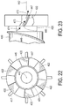
- Figures 22 and 23 illustrate additional aspects of the support struts 422.
- the support struts 422 include a leadings edge 445 and a trailing edge 447.
- the struts 422 may be angled with respect to the axis 442 of the device 400.
- the struts may have a constant angle, or the struts 422 may have a curved or variable angle. Other arrangements may prove suitable.
- the struts 422 having an angle may influence the direction of flow as the blood comes off the blades 446 on the rotor 440 as shown in Figure 23 , thus altering the direction as illustrated by the exemplary progression of flow arrows 471, 473 and 475.
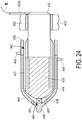
- Figure 24 illustrates the cross-section of the rotor 440 mounted to the stator 420 with the bearing 460 and the bearing 462.
- An annular gap 477 is defined between the rotor 440 and the stator 420.
- the apertures 451 allow limited flow communication between the gap 477 and the areas both in front of and behind the device 400.
- the example of Figure 24 also shows an exemplary form of incorporating the electrical coupling or power cord E into a portion 422a of one of the support struts 422. Using such an arrangement, effects of the power cord E on blood flow can be minimized. Further, the portion 422a may be suitably extended through the support assembly 413 to a convenient point to exit the blood vessel, again to minimize the effect on blood flow.
- Figure 25 shoes one exemplary form for the bearing 460.
- the bearing 460 includes a first race 478 mounted to the forward end 428 of the stator 420, and further includes a second race 480 mounted to an interior portion of the rotor 440.
- a washer or disc 482 surrounds the bearing 460.
- the disc 482 may function to hold back pressure external to the device 400, and may serve to minimize thrombus.
- a face 484 of the disc 482 may include grooves 486, which may be cut or etched into the face 484 of the disc 482.
- the flow housing may be sized to be approximately 20mm, while the blood vessel may typically measure approximately 30-40mm.
- the discussion of the devices 10 and 200 is applicable with equal force to the devices 300 and 400 as it relates to the operation of the associated power source 280 and controller 282.
- the device 10 is shown disposed about the aorta in a supravalvular position in order to assist with left ventricular failure.
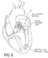
- the device 10 is shown disposed about the pulmonary artery, again in a supravalvular position, in order to assist with right ventricular failure.
- the device 10 may prove suitable for still other selected locations.
- Figures 8 and 9 may be combined, thus creating a bi-ventricular assist device by placing the device 10 in the aorta as shown in Figure 8 , and by placing another device in the pulmonary artery as shown in Figure 9 .
- the device 10 shown in each of Figures 8 and 9 may incorporate either the rotor 16 of Figures 2 and 3 , or may incorporate the rotor 116 of Figure 4 .
- the device 200 may be used.
- the device 10 is shown implanted within the body and coupled to the power source 32 and the timing control module 34 by one or more suitable links, with the power source 32 and the timing control module 34 incorporated into a single, implantable unit.
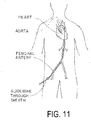
- Figure 11 illustrates percutaneous access to the desired location, in this case the aorta, via the femoral artery.
- the stent 12 in a collapsed configuration, is placed at the desired location above the aortic valve using a suitable guide wire and suitable known techniques as shown in Figure 12 .
- the stent 12 is expanded from the collapsed configuration of Figure 12 to an expanded configuration using an inflatable balloon and known techniques.
- stent 12 now defines the suitable flow path 14.
- the rotor 16 is advanced to the desired location within the stent 12, again using a suitable guide wire and known techniques.
- the rotor 16 may be expanded from a collapsed configuration during delivery to an expanded configuration by, for example, removing a sheath, or by using other suitable expansion techniques.
- the collar 26, as well as the power source 32, the timing control module 34, and the sensor 66 along with all suitable links, may be implanted using conventional techniques such as thoracoscopy, as illustrated in Figure 15 , or other suitable techniques.
- the placement of the device 200 is illustrated in Figures 16 and 17 .
- the stent 202 may be selected and placed at the selected location using known techniques in a collapsed configuration and then expanded from a collapsed configuration to an expanded configuration also using known techniques (e.g., through the use of an inflatable balloon).
- the combination of the stator 220 and the rotor 240 may be placed in an introducer jacket, which jacket collapses the blades 246 against the rotor 240.
- the support struts 222 may also be folded or otherwise collapsed against the stator 220.
- the introducer jacket is then introduced into the stent 202, and once the struts 222 are in place, the jacket may be removed.
- the removal of the jacket may cause the blades to extend from the outer surface 244 of the rotor 240, and places the device 200 in condition for use, as illustrated in Figure 17 .
- the power source 280, the controller 282, and the sensor 288, along with all suitable links, may be implanted using conventional techniques such as thoracoscopy, as is illustrated in Figure 15 relative to device 10, or other suitable techniques and operatively coupled to the device 200 (e.g., the power source 280 to windings of the stator 220).
- the device when assembled in accordance with an exemplary aspect of the invention, when the device is used for left ventricular support the device may be placed above the aortic valve and above the origins of the coronary arteries (for example, approximately 1 cm superior to the level of the sino-tubular junction). In such an application, coronary perfusion would not be affected.
- the device may be placed through the 2nd right intercostal space through an anterior mini-thoracotomy, off-pump, or through an upper hemisternotomy or traditional median sternotomy.
- one or more of the collar, the stent, and the rotor may be collapsible, and thus suitable for minimally invasive placement at the selected location(s).
- One exemplary a cardiac surgical approach would be a hybrid operating room with the placement of the impeller and stent percutaneously. Following a median sternotomy or upper hemisternotomy, once the aorta has been cross-clamped and the patient placed on cardiopulmonary bypass, the aorta could need to be incised.
- the decision whether to remove the native aortic valve would be based on its integrity and condition.
- the device would be mounted above the origins of the coronary arteries.
- the power source to the unit may be epi-aortic and would be threaded through subcutaneously to the location of the power pack.
- the device may be mounted on a titanium, or other suitable material, mesh stent-like structure, which would be lightweight and extremely strong.
- the device mechanism would be mounted within that mesh which would be sized appropriately to fit the aorta. In the case of pulmonary location, this would need to be placed in the supravalvular position in the pulmonary artery.
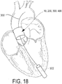
- the device (whether the device 10 or the device 200) may be placed using a trans-apical approach as illustrated in Figure 18 .
- the feasibility of the trans-apical approach is well described relative to its use for trans-apically delivered aortic valves.
- the aorta would not need to be incised, as the device would be inserted through the left ventricular apex via a mini-thoracotomy (left anterolateral incision, through the fifth or sixth intercostal space).
- a delivery catheter or guide wire 300 is introduced directly into the left ventricle using the mini-thoracotomy, and the catheter or guide wire 300 initially traverses the aortic valve under the guidance of trans-esophageal echocardiography and fluoroscopy to the appropriate position (e.g., above the origin of the coronary arteries).
- a sheath 302 may also be delivered to the left ventricular apex to maintain intraventricular access.
- the device 10, 200 may then be delivered through the sheath 302 over the catheter or guide wire 300 into place, first the stent and then the remainder of the device (the rotor or the rotor/stator combination, as collapsed within the introducer jacket, e.g.).
- This approach would minimize the risk of systemic embolization from a calcified aorta and would also avoid exposing the arterial circulation in candidates at risk of arterial compromise from embolization.
- the exemplary device of Figures 1-4 includes the rotor or impeller on a magnetic mount, such that the rotor is therefore magnetically suspended or levitated as outlined above.
- the impeller preferably includes a collapsible pumping surface or structure, such as collapsible blades or other suitable surface, which allow for percutaneous as well as trans-apical placement.
- the impeller may, in effect, function as a "suction" type of system. With each systolic contraction of the heart, the programming within the pacemaker-like timing control module or unit would activate the pumping action of the device.
- the rotor would speed up from its low baseline speed to a higher speed based on requirement, thus creating a negative vortex below it which would augment natural contractility of the heart as blood exits through the aorta and through the device. With diastole, the device would slow down or even stop. Keeping the rotor moving may be beneficial from a power conservation standpoint. Also, the stopped or very slowly moving rotor preferably functions in a valve-like capacity to prevent backflow of blood through the aorta or pulmonary artery and back into the ventricle. With the next cycle, the procedure would be repeated. The same method of installation and placement of the power source would be employed in the pulmonary position for right ventricular augmentation.
- the timing of the pump function would be optimized to provide phasic flow which would be coordinated with ventricular systole.
- a dual chamber or bi-ventricular pacemaker is often used to create synchronicity in contraction between the atrial and ventricular chambers. Placement of this device would not alter such function.
- the sensor 68 (or 288) includes electrodes which would be placed on the heart to obtain atrial and ventricular electrograms (the native cardiac rhythms) and this data would be sent to the timing control module 34 (or controller 282).
- the power source 32 (or 280) preferably is a pacemaker-like power source.
- the pumping function of the device 10 would be timed to coordinate with the ventricular electrical impulse indicating the onset of systole.
- a pressure sensor may also be provided and preferably would be available to detect changes in pressure thus providing additional information.
- the device 10 would be able to adapt to changing needs and changing heart rate conditions. This would result in augmentation of blood flow in a more synchronous fashion.
- the timing control module 34 would also have algorithms incorporated to take into account the timing of atrial and ventricular signals and input of pressure sensor data to indicate when pressure is rising, thus improving the timing of augmentation of phasic flow. In effect, the pump would increase its flow based on physiologic need. The mechanism is that the baseline speed of the impeller increases, thus forcing blood across the device at higher velocity and augmenting native cardiac function.
- systemic anticoagulation with traditional anticoagulants in the form of warfarin or low molecular weight heparin could be used with use of low dose aspirin as an anti-platelet agent.
- the device could be coated with material that prevents formation of thrombus. A non-thrombogenic surface would therefore minimize the need for systemic anticoagulation.
- the use of a direct current charge on the device by coating it with a dielectric and using a specific circuit to distribute the charge could be used (such as that found in PCT Publication No. WO 2008/024714 A1 ).
- the system could be coated with fibrinogen like peptide that would prevent thrombus formation and prevent the need for systemic anticoagulation.
- the unit including the power source 32 and the timing control module 34 preferably would be positioned as illustrated in Figure 9 .
- the power source would be placed in the infra-clavicular or sub diaphragmatic regions with subcutaneous wires to the device for power delivery as well as control of the device.
- the facility for near frequency communication (NFC) with the power source and control unit, via means of a cellular device (iphone, android device, blackberry RIM or "smart phone”) would be built into the system thus providing a means of wireless programming.
- the NFC control unit which the patient would carry would also provide a constant monitoring system providing information on power settings, cardiac output and display any potential problems which need to be addressed; default safety algorithms will be deployed and real-time data alerts will be sent to the on-call cardiology and cardiovascular team responsible for the patient from their home setting.
- the power source preferably would be transcutaneously charged. Therefore, the entire system would be completely implantable, with no external leads or wires. Still preferably, wireless cell phone technology or other suitable wireless communication protocols may be used, enabling the relevant health care providers to continuously monitor data from the cloud.
- the device as described functions in a synchronous fashion to augment cardiac contractility. Therefore if cardiac standstill occurs, or ventricular arrhythmias occur which prevent normal electrical activation, problems with device function could occur.
- One iteration of the device includes the use of a defibrillator lead which is attached to the power pack which can be used to sense the presence of ventricular arrhythmias and deliver an appropriate shock to the heart to terminate the arrhythmia. This would be necessary in order to provide continued cardiac output. This could be incorporated into the algorithms which would be programmed into the device. Atrial arrhythmias should not be as much of a problem, provided ventricular rate is maintained.
- the valve would be placed in the supra-aortic position.
- pure right ventricular failure it would be placed in the supra-pulmonary valve position.
- biventricular failure two devices could be employed sitting in the aorta and the pulmonary artery with appropriate power packs for each functioning device.
- the power packs could be placed in a infra-clavicular of infra-diaphragmatic location.
- the device In pulmonary hypertension with severe right heart failure, the device could be used in the supra-pulmonary valve position augmenting the function of the failing right ventricle. By virtue of its location, the etiology of the heart failure becomes less important. Thus, it could also be used in diastolic dysfunction and restrictive cardiomyopathic states. By simply augmenting device function and increasing the revolutions per minute during phasic contraction of the heart, the timing of diastolic filling becomes less important.
- the device would function adequately as a heart valve in addition to being an assist device. Hence, the native valves could be removed and the ability to stop or slow down the impeller completely would prevent backflow of blood and minimize forward flow of blood during the diastolic phase.
- the device could also be used as a peripheral circulatory assist device for severe peripheral vascular disease. In that iteration, it could be placed in the descending aorta or in the femoral or iliac vessels and thus augment blood flow to the lower limbs. Similarly, it could be placed in other locations within the aorta to augment blood flow in the relevant vascular beds. For instance, in individuals with severe peripheral vascular disease, placement of the device in the infra-renal position would augment natural blood flow and increase perfusion of the lower limbs. In critical lower limb ischemia, improvement of a proximal blood flow may allow the ability to treat the lower limb ischemia.
- the disclosed device and/or method may additionally prove especially useful or suitable for placement during congenital heart surgery in patients requiring hypoplastic left heart reconstruction.
- Those of skill in the art upon reading the present disclosure, will also find the disclosed device and/or method useful in other procedures as well.
- the disclosed device and/or method may also prove especially adaptable for certain energy saving or energy providing technology.
- the device may be adapted to extract and/or use kinetic energy from the heart and/or from the flow of blood, and use that energy to supply at least a portion of the power requirements of the device.
- the device may be especially suitable for use with bionic fuel cell power, which can extract electrons from blood glucose, thus supplying power to the device.
- bionic fuel cell technology can be found in Microfabricated Miniature Biofuel Cells with Nanoengineered Enzyme Electrodes, by Nishizawa et al. and Miniaturized Microfluidic Biofuel Cells, by Nishizawa .
Landscapes
- Health & Medical Sciences (AREA)
- Engineering & Computer Science (AREA)
- Heart & Thoracic Surgery (AREA)
- Biomedical Technology (AREA)
- Cardiology (AREA)
- General Health & Medical Sciences (AREA)
- Veterinary Medicine (AREA)
- Public Health (AREA)
- Life Sciences & Earth Sciences (AREA)
- Animal Behavior & Ethology (AREA)
- Mechanical Engineering (AREA)
- Anesthesiology (AREA)
- Hematology (AREA)
- Vascular Medicine (AREA)
- Transplantation (AREA)
- Oral & Maxillofacial Surgery (AREA)
- Physics & Mathematics (AREA)
- Fluid Mechanics (AREA)
- Computer Networks & Wireless Communication (AREA)
- Medical Informatics (AREA)
- Gastroenterology & Hepatology (AREA)
- Pulmonology (AREA)
- External Artificial Organs (AREA)
Claims (13)
- Ventrikularunterstützungsvorrichtung (300, 400) für ein menschliches Herz, welche aufweist:ein Strömungsgehäuse (302, 402), welches eine im Allgemeinen zylindrische Wand (304, 404) mit einer Innenfläche (306, 406) hat, welche einen Abschnitt eines Strömungspfads definiert, wobei das Strömungsgehäuse eine Außenfläche hat und die Größe des Strömungsgehäuses zur Anordnung innerhalb eines Blutgefäßes (312, 412) festgelegt ist,einen Stator (320, 420), welcher innerhalb des Strömungsgehäuses angeordnet werden kann, wobei der Stator eine Mehrzahl von Stützstreben (322, 422) hat, welche den Stator mit dem Strömungsgehäuse wirkkoppeln,einen Rotor (340, 440), welcher eine Außenfläche (344, 444) aufweist, welche der Innenfläche (306, 406) der zylindrischen Wand des Strömungsgehäuses gegenüberliegt, wobei der Rotor drehbar mit dem Stator gekoppelt ist und in Bezug auf den Stator um eine Drehachse drehbar ist, wobei der Rotor teilweise mittels zumindest einer Schaufel (346, 446) definiert ist, welche in Bezug auf die Drehachse in einem Winkel angeordnet ist,wobei einer des Rotors (340, 440) und des Stators (320, 420) einen Feldmagneten aufweist und der andere des Rotors und des Stators Wicklungen aufweist,wobei die Wicklungen zum Wirkkoppeln mit einer Leistungsquelle (280) und einer Steuereinheit (282) angeordnet sind, wobei die Leistungswicklungen angeordnet sind, um auf die Steuereinheit anzusprechen, um es der Leistungsquelle zu erlauben, die Drehgeschwindigkeit des Rotors (340, 440) zu variieren, wobei die Wicklungen mit einem Leistungskabel (E) elektrisch gekoppelt sind, und wobei zumindest ein Abschnitt des Leistungskabels (E) innerhalb einer Ausgewählten der Stützstreben (422) angeordnet ist, dadurch gekennzeichnet, dass die Ventrikularunterstützungsvorrichtung aufweist:ein Vaskulartransplantat (323, 423), welches das Strömungsgehäuse (402) umgibt und welches mit dem Strömungsgehäuse gekoppelt ist, wobei die Größe des Vaskulartransplantats zur Anordnung innerhalb des Blutgefäßes (312, 412) festgelegt ist und wobei das Vaskulartransplantat zum Koppeln mit dem Blutgefäß angeordnet ist, undeinen ringförmigen Raum (311, 411), welcher zwischen der Außenfläche des Strömungsgehäuses und dem Vaskulartransplantat (323, 423) definiert ist, wobei der ringförmige Raum (311, 411) einen Abschnitt eines zweiten Strömungspfads definiert.
- Vorrichtung gemäß Anspruch 1, wobei der Rotor (340, 440) den Feldmagneten aufweist und der Stator (320, 420) die Wicklungen aufweist, wobei die Wicklungen mit der Leistungsquelle wirkgekoppelt sind, oder der Stator (320, 420) ein stromaufwärtiges Ende (328, 428) und ein stromabwärtiges Ende (330, 430) hat, wobei die Mehrzahl von Stützstreben (322, 422) von dem stromabwärtigen Ende aus abhängen und mit dem Strömungsgehäuse verbunden sind.
- Vorrichtung gemäß Anspruch 1, welche ferner zumindest ein erstes und ein zweites Lager (360, 362, 460, 462) aufweist, welche zwischen dem Stator und dem Rotor angeordnet sind, um den Rotor am Stator drehbar zu montieren, wobei das erste Lager (360, 460) in Richtung eines stromaufwärtigen Endes des Rotors (340, 440) und des Stators (320, 420) angeordnet ist und das zweite Lager (460, 462) in Richtung eines stromabwärtigen Endes des Rotors (340, 440) und des Stators (320, 420) angeordnet ist, wobei das erste und das zweite Lager (360, 362, 460, 462) jeweilig ein magnetisches Lager sind, welches erste und zweite Magnete (364, 366) aufweist, wobei die ersten Magneten (364) am Rotor (340) angebracht sind und wobei die zweiten Magneten (366) am Stator (320) angebracht sind, wobei die ersten und die zweiten Magnete ausgerichtete Polaritäten haben.
- Vorrichtung gemäß Anspruch 1, wobei der Stator einen langgestreckten Körper (274) mit einem mechanischen Lager, welches benachbart zu einem ersten Ende angeordnet ist, und einem magnetischen Lager und der Mehrzahl von Stützstreben, welche benachbart zu einem zweiten Ende angeordnet sind, hat, und wobei der Rotor (240) einen langgestreckten, hohlen Körper (270) hat, welcher einen umschlossenen Raum (272) definiert, in welchem der langgestreckte Körper des Stators (220) angeordnet ist, wobei der Rotor mit dem Stator via das mechanische Lager am ersten Ende des Rotors und das magnetische Lager am zweiten Ende des Rotors verbunden ist.
- Vorrichtung gemäß Anspruch 1, wobei das Vaskulartransplantat (323, 423) mit dem Strömungsgehäuse mittels einer Mehrzahl von Stützen (413) oder mittels einer Netzstütze gekoppelt ist oder die zylindrische Stentwand ein Metallnetzrohr aufweist.
- Vorrichtung gemäß Anspruch 1, wobei der Rotor (340, 440) den Feldmagneten aufweist und der Stator (320, 420) die Wicklungen aufweist, wobei die Wicklungen mit der Leistungsquelle wirkgekoppelt sind, und wobei der Stator (320, 420) ein stromaufwärtiges Ende (328, 428) und ein stromabwärtiges Ende (330, 430) hat, wobei die Mehrzahl von Stützstreben (322, 422) von benachbart zum stromabwärtigen Ende des Stators aus abhängen und mit der Innenfläche des Strömungsgehäuses verbunden sind.
- Vorrichtung gemäß Anspruch 1, welche ferner zumindest ein erstes und ein zweites Lager (360, 362, 460, 462) aufweist, welche zwischen dem Stator und dem Rotor angeordnet sind, um den Rotor am Stator drehbar zu montieren, wobei das erste Lager (360, 460) benachbart zu einem stromaufwärtigen Ende des Rotors (340, 440) und des Stators (320, 420) angeordnet ist und wobei das zweite Lager (460, 462) benachbart zu einem stromabwärtigen Ende des Rotors (340, 440) und des Stators (320, 420) angeordnet ist, wobei das erste Lager (360) ein mechanischer Drehpunkt ist und das zweite Lager (362) ein magnetisches Lager ist und erste und zweite Magnete aufweist, wobei die ersten Magnete am Rotor angebracht sind und wobei die zweiten Magnete am Stator angebracht sind, wobei die ersten und die zweiten Magnete ausgerichtete Polaritäten haben.
- Vorrichtung gemäß Anspruch 7, wobei das erste Lager (360) ein hydrodynamischer Drehpunkt ist und das zweite Lager (362) ein magnetisches Lager ist und erste und zweite Magnete aufweist, wobei die ersten Magnete am Rotor angebracht sind und wobei die zweiten Magnete am Stator angebracht sind, wobei die ersten und die zweiten Magnete ausgerichtete Polaritäten haben.
- Vorrichtung gemäß Anspruch 1, wobei die zumindest eine Schaufel (346, 446) eine konstante Steigung oder eine variable Steigung hat.
- Vorrichtung gemäß Anspruch 1, wobei die Steuereinheit (282) programmiert ist, um die Leistungsquelle zu betätigen, um einen pulsierenden Strom bereitzustellen, oder um die Drehgeschwindigkeit des Rotors zwischen einer Grundlinie-Geschwindigkeit und einer höheren Geschwindigkeit zu steuern.
- Vorrichtung gemäß Anspruch 1, welche ferner einen Herzsensor (288) aufweist, welcher mit der Steuereinheit (282) wirkgekoppelt ist, wobei die Steuereinheit programmiert ist, um den Herzsensor zu verwenden, um native Herzrhythmen zu ermitteln, und um die Drehgeschwindigkeit des Rotors in Antwort auf die nativen Herzrhythmen zu steuern.
- Vorrichtung gemäß Anspruch 1, wobei die Größe des Stents, des Rotors (340, 440) und des Stators (320, 420) festgelegt sind, um in eines von der Aorta und der Lungenarterie oder in eines von der Aorta und der Lungenarterie an einer ausgewählten Stelle, welche supravalvulär ist, zu passen, oder wobei einer oder mehrere des Stents, des Stators und des Rotors mit einem Antikoagulans beschichtet sind.
- Die Vorrichtung gemäß irgendeinem der vorherigen Ansprüche, wobei die Größe der Leistungsquelle (280) und der Steuereinheit (282) für eine subkutane Anordnung festgelegt sind, oder wobei die Leistungsquelle für transkutanes Aufladen angeordnet ist, oder wobei die Steuereinheit für transkutanes Programmieren angeordnet ist.
Applications Claiming Priority (2)
| Application Number | Priority Date | Filing Date | Title |
|---|---|---|---|
| US201461944490P | 2014-02-25 | 2014-02-25 | |
| PCT/US2015/017499 WO2015130768A2 (en) | 2014-02-25 | 2015-02-25 | Ventricular assist device and method |
Publications (3)
| Publication Number | Publication Date |
|---|---|
| EP3110468A2 EP3110468A2 (de) | 2017-01-04 |
| EP3110468A4 EP3110468A4 (de) | 2017-10-04 |
| EP3110468B1 true EP3110468B1 (de) | 2021-11-03 |
Family
ID=54009771
Family Applications (1)
| Application Number | Title | Priority Date | Filing Date |
|---|---|---|---|
| EP15755879.2A Active EP3110468B1 (de) | 2014-02-25 | 2015-02-25 | Ventrikuläre hilfsvorrichtung und verfahren |
Country Status (4)
| Country | Link |
|---|---|
| US (2) | US10426880B2 (de) |
| EP (1) | EP3110468B1 (de) |
| AU (1) | AU2015223169B2 (de) |
| WO (1) | WO2015130768A2 (de) |
Cited By (16)
| Publication number | Priority date | Publication date | Assignee | Title |
|---|---|---|---|---|
| US11311376B2 (en) | 2019-06-20 | 2022-04-26 | Neovase Tiara Inc. | Low profile prosthetic mitral valve |
| US11357622B2 (en) | 2016-01-29 | 2022-06-14 | Neovase Tiara Inc. | Prosthetic valve for avoiding obstruction of outflow |
| US11389294B2 (en) | 2012-05-30 | 2022-07-19 | Neovasc Tiara Inc. | Methods and apparatus for loading a prosthesis onto a delivery system |
| US11389291B2 (en) | 2013-04-04 | 2022-07-19 | Neovase Tiara Inc. | Methods and apparatus for delivering a prosthetic valve to a beating heart |
| US11413139B2 (en) | 2011-11-23 | 2022-08-16 | Neovasc Tiara Inc. | Sequentially deployed transcatheter mitral valve prosthesis |
| US11419720B2 (en) | 2010-05-05 | 2022-08-23 | Neovasc Tiara Inc. | Transcatheter mitral valve prosthesis |
| US11464631B2 (en) | 2016-11-21 | 2022-10-11 | Neovasc Tiara Inc. | Methods and systems for rapid retraction of a transcatheter heart valve delivery system |
| US11491006B2 (en) | 2019-04-10 | 2022-11-08 | Neovasc Tiara Inc. | Prosthetic valve with natural blood flow |
| US11497602B2 (en) | 2012-02-14 | 2022-11-15 | Neovasc Tiara Inc. | Methods and apparatus for engaging a valve prosthesis with tissue |
| US11602429B2 (en) | 2019-04-01 | 2023-03-14 | Neovasc Tiara Inc. | Controllably deployable prosthetic valve |
| US11654275B2 (en) | 2019-07-22 | 2023-05-23 | Shifamed Holdings, Llc | Intravascular blood pumps with struts and methods of use and manufacture |
| US11737872B2 (en) | 2018-11-08 | 2023-08-29 | Neovasc Tiara Inc. | Ventricular deployment of a transcatheter mitral valve prosthesis |
| US11779742B2 (en) | 2019-05-20 | 2023-10-10 | Neovasc Tiara Inc. | Introducer with hemostasis mechanism |
| US11793640B2 (en) | 2017-08-25 | 2023-10-24 | Neovasc Tiara Inc. | Sequentially deployed transcatheter mitral valve prosthesis |
| US11998447B2 (en) | 2019-03-08 | 2024-06-04 | Neovasc Tiara Inc. | Retrievable prosthesis delivery system |
| US12109111B2 (en) | 2015-12-15 | 2024-10-08 | Neovasc Tiara Inc. | Transseptal delivery system |
Families Citing this family (60)
| Publication number | Priority date | Publication date | Assignee | Title |
|---|---|---|---|---|
| AU2009302904B2 (en) * | 2008-10-10 | 2016-03-03 | Medicaltree Patent Ltd | An improved artificial valve |
| ES2959221T3 (es) | 2015-09-25 | 2024-02-21 | Procyrion Inc | Bomba de sangre intravascular no oclusiva que proporciona hemólisis reducida |
| US12064614B2 (en) | 2016-03-21 | 2024-08-20 | Ramtin Agah | Methods and systems for deployment, charging and retrieval of intracardiac pumps |
| US11406812B2 (en) | 2016-03-21 | 2022-08-09 | Ramtin Agah | Methods and systems for deployment, charging and retrieval of intracardiac pumps |
| DE102016209871A1 (de) | 2016-06-06 | 2017-12-07 | Robert Bosch Gmbh | Stanzvorrichtung und Verfahren zum Stanzen eines Lumens und Implantieren einer Implantateinrichtung |
| US10675395B2 (en) * | 2016-06-23 | 2020-06-09 | Boston Scientific Scimed, Inc. | Pulmonary-systemic shunt devices and related methods |
| US9839734B1 (en) | 2016-12-02 | 2017-12-12 | Berlin Heart Gmbh | Aortic pump devices and methods |
| CA3049227A1 (en) * | 2017-01-06 | 2018-07-12 | Benjamin Sun | Implantable intravascular ventricular assist device |
| EP4732889A2 (de) | 2017-06-07 | 2026-04-29 | Supira Medical, Inc. | Vorrichtungen, systeme und verfahren zur bewegung intravaskulärer flüssigkeiten |
| US11511103B2 (en) | 2017-11-13 | 2022-11-29 | Shifamed Holdings, Llc | Intravascular fluid movement devices, systems, and methods of use |
| DE102018201030B4 (de) | 2018-01-24 | 2025-10-16 | Kardion Gmbh | Magnetkuppelelement mit magnetischer Lagerungsfunktion |
| JP7410034B2 (ja) | 2018-02-01 | 2024-01-09 | シファメド・ホールディングス・エルエルシー | 血管内血液ポンプならびに使用および製造の方法 |
| US11690997B2 (en) | 2018-04-06 | 2023-07-04 | Puzzle Medical Devices Inc. | Mammalian body conduit intralumenal device and lumen wall anchor assembly, components thereof and methods of implantation and explanation thereof |
| DE102018206750A1 (de) | 2018-05-02 | 2019-11-07 | Kardion Gmbh | Vorrichtung zur induktiven Energieübertragung in einen menschlichen Körper und deren Verwendung |
| DE102018206724A1 (de) | 2018-05-02 | 2019-11-07 | Kardion Gmbh | Energieübertragungssystem und Verfahren zur drahtlosen Energieübertragung |
| DE102018206754A1 (de) | 2018-05-02 | 2019-11-07 | Kardion Gmbh | Verfahren und Vorrichtung zur Bestimmung der Temperatur an einer Oberfläche sowie Verwendung des Verfahrens |
| DE102018206727A1 (de) | 2018-05-02 | 2019-11-07 | Kardion Gmbh | Energieübertragungssystem und Empfangseinheit zur drahtlosen transkutanen Energieübertragung |
| DE102018206731A1 (de) | 2018-05-02 | 2019-11-07 | Kardion Gmbh | Vorrichtung zur induktiven Energieübertragung in einen menschlichen Körper und Verwendung der Vorrichtung |
| DE102018206725A1 (de) | 2018-05-02 | 2019-11-07 | Kardion Gmbh | Empfangseinheit, Sendeeinheit, Energieübertragungssystem und Verfahren zur drahtlosen Energieübertragung |
| DE102018207575A1 (de) | 2018-05-16 | 2019-11-21 | Kardion Gmbh | Magnetische Stirndreh-Kupplung zur Übertragung von Drehmomenten |
| DE102018207611A1 (de) | 2018-05-16 | 2019-11-21 | Kardion Gmbh | Rotorlagerungssystem |
| DE102018207594A1 (de) | 2018-05-16 | 2019-11-21 | Kardion Gmbh | Rotor, Magnetkupplungsvorrichtung, Elektromotor für ein Herzunterstützungssystem, Pumpeneinheit für ein Herzunterstützungssystem sowie Verfahren zum Herstellen eines Rotors |
| DE102018208539A1 (de) | 2018-05-30 | 2019-12-05 | Kardion Gmbh | Motorgehäusemodul zum Abdichten eines Motorraums eines Motors eines Herzunterstützungssystems und Herzunterstützungssystem und Verfahren zum Montieren eines Herzunterstützungssystems |
| DE102018208555A1 (de) | 2018-05-30 | 2019-12-05 | Kardion Gmbh | Vorrichtung zum Verankern eines Herzunterstützungssystems in einem Blutgefäß, Verfahren zum Betreiben und Herstellverfahren zum Herstellen einer Vorrichtung und Herzunterstützungssystem |
| DE102018208549A1 (de) | 2018-05-30 | 2019-12-05 | Kardion Gmbh | Elektronikmodul für ein Herzunterstützungssystem und Verfahren zum Herstellen eines Elektronikmoduls für ein Herzunterstützungssystem |
| DE102018208541A1 (de) | 2018-05-30 | 2019-12-05 | Kardion Gmbh | Axialpumpe für ein Herzunterstützungssystem und Verfahren zum Herstellen einer Axialpumpe für ein Herzunterstützungssystem |
| DE102018208538A1 (de) | 2018-05-30 | 2019-12-05 | Kardion Gmbh | Intravasale Blutpumpe und Verfahren zur Herstellung von elektrischen Leiterbahnen |
| DE102018208550A1 (de) | 2018-05-30 | 2019-12-05 | Kardion Gmbh | Leitungsvorrichtung zum Leiten eines Blutstroms für ein Herzunterstützungssystem, Herzunterstützungssystem und Verfahren zum Herstellen einer Leitungsvorrichtung |
| DE102018210076A1 (de) | 2018-06-21 | 2019-12-24 | Kardion Gmbh | Verfahren und Vorrichtung zum Erkennen eines Verschleißzustands eines Herzunterstützungssystems, Verfahren und Vorrichtung zum Betreiben eines Herzunterstützungssystems und Herzunterstützungssystem |
| DE102018210058A1 (de) | 2018-06-21 | 2019-12-24 | Kardion Gmbh | Statorschaufelvorrichtung zur Strömungsführung eines aus einer Austrittsöffnung eines Herzunterstützungssystems ausströmenden Fluids, Herzunterstützungssystem mit Statorschaufelvorrichtung, Verfahren zum Betreiben einer Statorschaufelvorrichtung und Herstellverfahren |
| DE102018211297A1 (de) | 2018-07-09 | 2020-01-09 | Kardion Gmbh | Herzunterstützungssystem und Verfahren zur Überwachung der Integrität einer Haltestruktur eines Herzunterstützungssystems |
| DE102018211327A1 (de) | 2018-07-10 | 2020-01-16 | Kardion Gmbh | Laufrad für ein implantierbares, vaskuläres Unterstützungssystem |
| DE102018211328A1 (de) | 2018-07-10 | 2020-01-16 | Kardion Gmbh | Laufradgehäuse für ein implantierbares, vaskuläres Unterstützungssystem |
| DE102018212153A1 (de) | 2018-07-20 | 2020-01-23 | Kardion Gmbh | Zulaufleitung für eine Pumpeneinheit eines Herzunterstützungssystems, Herzunterstützungssystem und Verfahren zum Herstellen einer Zulaufleitung für eine Pumpeneinheit eines Herzunterstützungssystems |
| US11793993B2 (en) * | 2018-07-30 | 2023-10-24 | Michael Siegenthaler | Open electric pump |
| WO2020028537A1 (en) | 2018-07-31 | 2020-02-06 | Shifamed Holdings, Llc | Intravascaular blood pumps and methods of use |
| AU2019320533B2 (en) | 2018-08-07 | 2024-11-21 | Kardion Gmbh | Bearing device for a cardiac support system, and method for flushing an intermediate space in a bearing device for a cardiac support system |
| WO2020073047A1 (en) | 2018-10-05 | 2020-04-09 | Shifamed Holdings, Llc | Intravascular blood pumps and methods of use |
| CN119113374A (zh) | 2019-03-26 | 2024-12-13 | 益智医疗器械股份有限公司 | 模块化哺乳动物身体可植入流体流动影响装置和相关方法 |
| WO2021011473A1 (en) | 2019-07-12 | 2021-01-21 | Shifamed Holdings, Llc | Intravascular blood pumps and methods of manufacture and use |
| EP4010046A4 (de) | 2019-08-07 | 2023-08-30 | Calomeni, Michael | Katheterblutpumpen und zusammenklappbare pumpengehäuse |
| EP4034192B1 (de) | 2019-09-25 | 2025-12-24 | Supira Medical, Inc. | Intravaskuläre blutpumpensysteme und verfahren zur verwendung und steuerung davon |
| EP4034221B1 (de) | 2019-09-25 | 2024-11-13 | Shifamed Holdings, LLC | Katheterblutpumpen und zusammenklappbare pumpengehäuse |
| WO2021062260A1 (en) | 2019-09-25 | 2021-04-01 | Shifamed Holdings, Llc | Catheter blood pumps and collapsible blood conduits |
| US12383723B2 (en) | 2019-10-05 | 2025-08-12 | Puzzle Medical Devices Inc. | Mammalian body implantable fluid flow influencing device |
| CA3160442A1 (en) | 2019-12-03 | 2021-06-10 | Procyrion, Inc. | Blood pumps |
| EP4072650A4 (de) | 2019-12-11 | 2024-01-10 | Shifamed Holdings, LLC | Absteigende aorten- und hohlvenenblutpumpen |
| WO2021119413A1 (en) | 2019-12-13 | 2021-06-17 | Procyrion, Inc. | Support structures for intravascular blood pumps |
| US12599758B2 (en) | 2019-12-19 | 2026-04-14 | Shifamed Holdings, Llc | Intravascular blood pumps, motors, and fluid control |
| DE102020102474A1 (de) | 2020-01-31 | 2021-08-05 | Kardion Gmbh | Pumpe zum Fördern eines Fluids und Verfahren zum Herstellen einer Pumpe |
| EP3915607B1 (de) * | 2020-05-26 | 2024-07-03 | Systol Dynamics | Vorrichtung zum entladen des linken ventrikels |
| CA3192451A1 (en) | 2020-09-14 | 2022-03-17 | Johannes Bette | Cardiovascular support pump having an impeller with a variable flow area |
| US11699551B2 (en) | 2020-11-05 | 2023-07-11 | Kardion Gmbh | Device for inductive energy transmission in a human body and use of the device |
| WO2022108836A1 (en) * | 2020-11-17 | 2022-05-27 | Mi-Vad, Inc | Ventricular assist device and method |
| JP2023550938A (ja) | 2020-11-20 | 2023-12-06 | カルディオン ゲーエムベーハー | ガイドワイヤ補助具付き機械的循環支持システム |
| CN118215524A (zh) * | 2021-11-16 | 2024-06-18 | 波士顿科学国际有限公司 | 有利于减少溶血的经皮循环支持系统 |
| CN114796847B (zh) * | 2022-04-19 | 2026-01-16 | 安徽通灵仿生科技有限公司 | 一种叶轮及心室辅助装置 |
| EP4531984A4 (de) * | 2022-05-24 | 2025-12-03 | Cardioforma Llc | Perkutane endovaskuläre zentrifugalherzpumpe und verfahren |
| IL320366A (en) | 2022-11-01 | 2025-06-01 | Puzzle Medical Devices Inc | Missile medical devices and methods related thereto |
| CN119971299B (zh) * | 2025-04-11 | 2025-06-20 | 四川大学华西医院 | 瓣泵一体化串联式心室辅助循环装置 |
Family Cites Families (99)
| Publication number | Priority date | Publication date | Assignee | Title |
|---|---|---|---|---|
| US4382199A (en) | 1980-11-06 | 1983-05-03 | Nu-Tech Industries, Inc. | Hydrodynamic bearing system for a brushless DC motor |
| US5078741A (en) | 1986-10-12 | 1992-01-07 | Life Extenders Corporation | Magnetically suspended and rotated rotor |
| US4944748A (en) | 1986-10-12 | 1990-07-31 | Bramm Gunter W | Magnetically suspended and rotated rotor |
| US4625712A (en) | 1983-09-28 | 1986-12-02 | Nimbus, Inc. | High-capacity intravascular blood pump utilizing percutaneous access |
| US4753221A (en) | 1986-10-22 | 1988-06-28 | Intravascular Surgical Instruments, Inc. | Blood pumping catheter and method of use |
| US4779614A (en) | 1987-04-09 | 1988-10-25 | Nimbus Medical, Inc. | Magnetically suspended rotor axial flow blood pump |
| US4817586A (en) | 1987-11-24 | 1989-04-04 | Nimbus Medical, Inc. | Percutaneous bloom pump with mixed-flow output |
| US4908012A (en) | 1988-08-08 | 1990-03-13 | Nimbus Medical, Inc. | Chronic ventricular assist system |
| JPH0653161B2 (ja) | 1988-09-28 | 1994-07-20 | 東洋紡績株式会社 | 循環装置 |
| US4919647A (en) | 1988-10-13 | 1990-04-24 | Kensey Nash Corporation | Aortically located blood pumping catheter and method of use |
| US4957504A (en) | 1988-12-02 | 1990-09-18 | Chardack William M | Implantable blood pump |
| US4995857A (en) | 1989-04-07 | 1991-02-26 | Arnold John R | Left ventricular assist device and method for temporary and permanent procedures |
| US5049134A (en) | 1989-05-08 | 1991-09-17 | The Cleveland Clinic Foundation | Sealless heart pump |
| US5112202A (en) | 1990-01-31 | 1992-05-12 | Ntn Corporation | Turbo pump with magnetically supported impeller |
| JPH0636821B2 (ja) | 1990-03-08 | 1994-05-18 | 健二 山崎 | 体内埋設形の補助人工心臓 |
| US5290227A (en) | 1992-08-06 | 1994-03-01 | Pasque Michael K | Method of implanting blood pump in ascending aorta or main pulmonary artery |
| US5676651A (en) | 1992-08-06 | 1997-10-14 | Electric Boat Corporation | Surgically implantable pump arrangement and method for pumping body fluids |
| SE501215C2 (sv) | 1992-09-02 | 1994-12-12 | Oeyvind Reitan | Kateterpump |
| US5947892A (en) | 1993-11-10 | 1999-09-07 | Micromed Technology, Inc. | Rotary blood pump |
| US5527159A (en) | 1993-11-10 | 1996-06-18 | The United States Of America As Represented By The Administrator Of The National Aeronautics And Space Administration | Rotary blood pump |
| EP1402908A3 (de) | 1994-04-15 | 2005-04-27 | Allegheny-Singer Research Institute | Blutpumpe und Herstellungsverfahren |
| US5762599A (en) | 1994-05-02 | 1998-06-09 | Influence Medical Technologies, Ltd. | Magnetically-coupled implantable medical devices |
| US5507629A (en) | 1994-06-17 | 1996-04-16 | Jarvik; Robert | Artificial hearts with permanent magnet bearings |
| US5613935A (en) | 1994-12-16 | 1997-03-25 | Jarvik; Robert | High reliability cardiac assist system |
| US5924975A (en) | 1995-08-30 | 1999-07-20 | International Business Machines Corporation | Linear pump |
| US5695471A (en) | 1996-02-20 | 1997-12-09 | Kriton Medical, Inc. | Sealless rotary blood pump with passive magnetic radial bearings and blood immersed axial bearings |
| US5840070A (en) | 1996-02-20 | 1998-11-24 | Kriton Medical, Inc. | Sealless rotary blood pump |
| DE19613564C1 (de) | 1996-04-04 | 1998-01-08 | Guenter Prof Dr Rau | Intravasale Blutpumpe |
| US6244835B1 (en) | 1996-06-26 | 2001-06-12 | James F. Antaki | Blood pump having a magnetically suspended rotor |
| US6015272A (en) | 1996-06-26 | 2000-01-18 | University Of Pittsburgh | Magnetically suspended miniature fluid pump and method of designing the same |
| DE19629614A1 (de) | 1996-07-23 | 1998-01-29 | Cardiotools Herzchirurgietechn | Linksherzassistpumpe |
| US5851174A (en) | 1996-09-17 | 1998-12-22 | Robert Jarvik | Cardiac support device |
| US5964694A (en) | 1997-04-02 | 1999-10-12 | Guidant Corporation | Method and apparatus for cardiac blood flow assistance |
| AUPO902797A0 (en) | 1997-09-05 | 1997-10-02 | Cortronix Pty Ltd | A rotary blood pump with hydrodynamically suspended impeller |
| US6123725A (en) | 1997-07-11 | 2000-09-26 | A-Med Systems, Inc. | Single port cardiac support apparatus |
| US6610004B2 (en) | 1997-10-09 | 2003-08-26 | Orqis Medical Corporation | Implantable heart assist system and method of applying same |
| UA56262C2 (uk) | 1997-10-09 | 2003-05-15 | Орквіс Медікел Корпорейшн | Імплантовувана система підтримки серця |
| US6889082B2 (en) | 1997-10-09 | 2005-05-03 | Orqis Medical Corporation | Implantable heart assist system and method of applying same |
| US6201329B1 (en) | 1997-10-27 | 2001-03-13 | Mohawk Innovative Technology, Inc. | Pump having magnetic bearing for pumping blood and the like |
| US5928131A (en) | 1997-11-26 | 1999-07-27 | Vascor, Inc. | Magnetically suspended fluid pump and control system |
| US6293901B1 (en) | 1997-11-26 | 2001-09-25 | Vascor, Inc. | Magnetically suspended fluid pump and control system |
| US6176822B1 (en) | 1998-03-31 | 2001-01-23 | Impella Cardiotechnik Gmbh | Intracardiac blood pump |
| CA2330048C (en) | 1998-04-22 | 2004-04-20 | University Of Utah | Implantable centrifugal blood pump with hybrid magnetic bearings |
| DE19821307C1 (de) | 1998-05-13 | 1999-10-21 | Impella Cardiotech Gmbh | Intrakardiale Blutpumpe |
| US6135943A (en) | 1998-08-07 | 2000-10-24 | Cardiac Assist Technologies, Inc. | Non-invasive flow indicator for a rotary blood pump |
| US6245007B1 (en) | 1999-01-28 | 2001-06-12 | Terumo Cardiovascular Systems Corporation | Blood pump |
| WO2000062842A1 (de) | 1999-04-20 | 2000-10-26 | Berlin Heart Ag | Vorrichtung zur axialen förderung von fluiden medien |
| DE29921352U1 (de) | 1999-12-04 | 2001-04-12 | Impella Cardiotechnik AG, 52074 Aachen | Intravasale Blutpumpe |
| US20010039369A1 (en) | 1999-12-14 | 2001-11-08 | Terentiev Alexandre N. | Blood pump system |
| JP2001207988A (ja) | 2000-01-26 | 2001-08-03 | Nipro Corp | 磁気駆動型軸流ポンプ |
| DE10016422B4 (de) | 2000-04-01 | 2013-10-31 | Impella Cardiosystems Ag | Parakardiale Blutpumpe |
| DE10040403A1 (de) | 2000-08-18 | 2002-02-28 | Impella Cardiotech Ag | Intrakardiale Blutpumpe |
| DE10059714C1 (de) | 2000-12-01 | 2002-05-08 | Impella Cardiotech Ag | Intravasale Pumpe |
| US6761532B2 (en) | 2001-03-14 | 2004-07-13 | Vascor, Inc. | Touch down of blood pump impellers |
| WO2003041779A1 (en) | 2001-11-14 | 2003-05-22 | Emphasys Medical, Inc. | Active pump bronchial implant and methods of use thereof |
| US7238151B2 (en) | 2002-02-26 | 2007-07-03 | Frazier O Howard | Permanent heart assist system |
| US6716157B2 (en) | 2002-02-28 | 2004-04-06 | Michael P. Goldowsky | Magnetic suspension blood pump |
| US7029433B2 (en) | 2002-03-16 | 2006-04-18 | Chang Sheldon S | Device for cardiac restoration |
| US7998190B2 (en) | 2002-06-17 | 2011-08-16 | California Institute Of Technology | Intravascular miniature stent pump |
| ATE496651T1 (de) | 2002-08-02 | 2011-02-15 | Prosthesica Ag | Gerät zur verteilung von flüssigkeit im körper eines patienten |
| US6817836B2 (en) | 2002-09-10 | 2004-11-16 | Miwatec Incorporated | Methods and apparatus for controlling a continuous flow rotary blood pump |
| US7284956B2 (en) | 2002-09-10 | 2007-10-23 | Miwatec Co., Ltd. | Methods and apparatus for controlling a continuous flow rotary blood pump |
| DE10330434A1 (de) | 2003-07-04 | 2005-02-03 | Jostra Ag | Zentrifugal-Pumpe |
| US7229258B2 (en) | 2003-09-25 | 2007-06-12 | Medforte Research Foundation | Streamlined unobstructed one-pass axial-flow pump |
| US20050085683A1 (en) | 2003-10-15 | 2005-04-21 | Bolling Steven F. | Implantable heart assist system and method of applying same |
| WO2005042064A1 (en) | 2003-10-31 | 2005-05-12 | Ventracor Limited | Improved blood pump comprising polymeric components |
| AU2005272610B2 (en) * | 2004-08-13 | 2011-10-20 | Procyrion, Inc. | Method and apparatus for long-term assisting a left ventricle to pump blood |
| US20060083642A1 (en) | 2004-10-18 | 2006-04-20 | Cook Martin C | Rotor stability of a rotary pump |
| US8419609B2 (en) * | 2005-10-05 | 2013-04-16 | Heartware Inc. | Impeller for a rotary ventricular assist device |
| US7699586B2 (en) | 2004-12-03 | 2010-04-20 | Heartware, Inc. | Wide blade, axial flow pump |
| US7479102B2 (en) | 2005-02-28 | 2009-01-20 | Robert Jarvik | Minimally invasive transvalvular ventricular assist device |
| US20090069854A1 (en) | 2005-04-21 | 2009-03-12 | Eqlibra Medical Ltd. | Implantable electric device |
| EP1898971B1 (de) | 2005-06-06 | 2015-03-11 | The Cleveland Clinic Foundation | Blutpumpe |
| US7878967B1 (en) | 2005-10-06 | 2011-02-01 | Sanjaya Khanal | Heart failure/hemodynamic device |
| US7850594B2 (en) | 2006-05-09 | 2010-12-14 | Thoratec Corporation | Pulsatile control system for a rotary blood pump |
| AU2007266459B2 (en) | 2006-05-31 | 2013-01-17 | Star Bp, Inc. | Heart assist device |
| EP2053981B1 (de) | 2006-08-21 | 2015-11-18 | Mayo Foundation For Medical Education And Research | Kontrollvorrichtung für gerinnselbildung |
| WO2008027597A2 (en) | 2006-08-31 | 2008-03-06 | Smartin Technologies, Llc | Implantable fluid pump |
| US20080200750A1 (en) | 2006-11-17 | 2008-08-21 | Natalie James | Polymer encapsulation for medical device |
| US20090112312A1 (en) | 2007-02-26 | 2009-04-30 | Larose Jeffrey A | Intravascular ventricular assist device |
| US7762941B2 (en) | 2007-04-25 | 2010-07-27 | Robert Jarvik | Blood pump bearings with separated contact surfaces |
| US8075472B2 (en) * | 2007-05-03 | 2011-12-13 | Leviticus-Cardio Ltd. | Permanent ventricular assist device for treating heart failure |
| US9199020B2 (en) | 2007-11-01 | 2015-12-01 | Abiomed, Inc. | Purge-free miniature rotary pump |
| US20090204205A1 (en) | 2008-02-08 | 2009-08-13 | Larose Jeffrey A | Platinum-cobalt-boron blood pump element |
| EP2249746B1 (de) | 2008-02-08 | 2018-10-03 | Heartware, Inc. | Ventrikuläres unterstützungssystem zur intraventrikulären platzierung |
| GB0813603D0 (en) | 2008-07-25 | 2008-09-03 | Cardio Carbon Technology Ltd | Ventricular assist system |
| EP2315609B1 (de) | 2008-08-08 | 2015-12-02 | Calon Cardio Technology Ltd | Gerät zur unterstützung der herzfunktion |
| AU2009302931B2 (en) | 2008-10-10 | 2015-10-29 | Medicaltree Patent Ltd | Heart help pump, system, and method |
| US8550974B2 (en) | 2008-11-13 | 2013-10-08 | Robert Jarvik | Sub-miniature electromechanical medical implants with integrated hermetic feedthroughs |
| TWM354093U (en) | 2008-11-14 | 2009-04-01 | Primax Electronics Ltd | Portable camera having a lens module switching unit |
| EP2266640A1 (de) | 2009-06-25 | 2010-12-29 | ECP Entwicklungsgesellschaft mbH | Komprimierbares und expandierbares Schaufelblatt für eine Fluidpumpe |
| EP2506888B1 (de) | 2009-12-03 | 2020-02-05 | Oregon Health & Science University | Vollständig künstliches herz |
| US8734508B2 (en) | 2009-12-21 | 2014-05-27 | Boston Scientific Scimed, Inc. | Systems and methods for making and using percutaneously-delivered pumping systems for providing hemodynamic support |
| EP2338541A1 (de) | 2009-12-23 | 2011-06-29 | ECP Entwicklungsgesellschaft mbH | Radial komprimierbarer und expandierbarer Rotor für eine Fluidpumpe |
| EP2363157A1 (de) | 2010-03-05 | 2011-09-07 | ECP Entwicklungsgesellschaft mbH | Vorrichtung zur mechanischen Einwirkung auf ein Medium, insbesondere Fluidpumpe |
| US20130138205A1 (en) * | 2011-11-28 | 2013-05-30 | MI-VAD, Inc. | Ventricular assist device and method |
| CN104185481B (zh) | 2012-02-07 | 2017-02-22 | 赫莱达雅公司 | 血液动力学辅助设备 |
| DE102012207049A1 (de) | 2012-04-27 | 2015-08-13 | Abiomed Europe Gmbh | Intravasale rotationsblutpumpe |
| US10124102B2 (en) | 2012-12-20 | 2018-11-13 | Oran Bulent | Endovascular permanent heart assist device |
-
2015
- 2015-02-25 EP EP15755879.2A patent/EP3110468B1/de active Active
- 2015-02-25 WO PCT/US2015/017499 patent/WO2015130768A2/en not_active Ceased
- 2015-02-25 AU AU2015223169A patent/AU2015223169B2/en active Active
- 2015-02-25 US US15/121,708 patent/US10426880B2/en active Active
-
2019
- 2019-07-31 US US16/528,251 patent/US11154700B2/en active Active
Cited By (24)
| Publication number | Priority date | Publication date | Assignee | Title |
|---|---|---|---|---|
| US11419720B2 (en) | 2010-05-05 | 2022-08-23 | Neovasc Tiara Inc. | Transcatheter mitral valve prosthesis |
| US12611303B2 (en) | 2010-05-05 | 2026-04-28 | Neovasc Tiara Inc. | Transcatheter mitral valve prosthesis |
| US12053369B2 (en) | 2011-11-23 | 2024-08-06 | Neovasc Tiara Inc. | Sequentially deployed transcatheter mitral valve prosthesis |
| US11413139B2 (en) | 2011-11-23 | 2022-08-16 | Neovasc Tiara Inc. | Sequentially deployed transcatheter mitral valve prosthesis |
| US11497602B2 (en) | 2012-02-14 | 2022-11-15 | Neovasc Tiara Inc. | Methods and apparatus for engaging a valve prosthesis with tissue |
| US12138159B2 (en) | 2012-02-14 | 2024-11-12 | Neovasc Tiara Inc. | Methods and apparatus for engaging a valve prosthesis with tissue |
| US11389294B2 (en) | 2012-05-30 | 2022-07-19 | Neovasc Tiara Inc. | Methods and apparatus for loading a prosthesis onto a delivery system |
| US11617650B2 (en) | 2012-05-30 | 2023-04-04 | Neovasc Tiara Inc. | Methods and apparatus for loading a prosthesis onto a delivery system |
| US11389291B2 (en) | 2013-04-04 | 2022-07-19 | Neovase Tiara Inc. | Methods and apparatus for delivering a prosthetic valve to a beating heart |
| US12109111B2 (en) | 2015-12-15 | 2024-10-08 | Neovasc Tiara Inc. | Transseptal delivery system |
| US11357622B2 (en) | 2016-01-29 | 2022-06-14 | Neovase Tiara Inc. | Prosthetic valve for avoiding obstruction of outflow |
| US12193932B2 (en) | 2016-01-29 | 2025-01-14 | Neovasc Tiara Inc. | Prosthetic valve for avoiding obstruction of outflow |
| US11464631B2 (en) | 2016-11-21 | 2022-10-11 | Neovasc Tiara Inc. | Methods and systems for rapid retraction of a transcatheter heart valve delivery system |
| US12201524B2 (en) | 2016-11-21 | 2025-01-21 | Neovasc Tiara Inc. | Methods and systems for rapid retraction of a transcatheter heart valve delivery system |
| US11793640B2 (en) | 2017-08-25 | 2023-10-24 | Neovasc Tiara Inc. | Sequentially deployed transcatheter mitral valve prosthesis |
| US11737872B2 (en) | 2018-11-08 | 2023-08-29 | Neovasc Tiara Inc. | Ventricular deployment of a transcatheter mitral valve prosthesis |
| US11998447B2 (en) | 2019-03-08 | 2024-06-04 | Neovasc Tiara Inc. | Retrievable prosthesis delivery system |
| US11602429B2 (en) | 2019-04-01 | 2023-03-14 | Neovasc Tiara Inc. | Controllably deployable prosthetic valve |
| US12036117B2 (en) | 2019-04-10 | 2024-07-16 | Neovasc Tiara Inc. | Prosthetic valve with natural blood flow |
| US11491006B2 (en) | 2019-04-10 | 2022-11-08 | Neovasc Tiara Inc. | Prosthetic valve with natural blood flow |
| US11779742B2 (en) | 2019-05-20 | 2023-10-10 | Neovasc Tiara Inc. | Introducer with hemostasis mechanism |
| US11931254B2 (en) | 2019-06-20 | 2024-03-19 | Neovasc Tiara Inc. | Low profile prosthetic mitral valve |
| US11311376B2 (en) | 2019-06-20 | 2022-04-26 | Neovase Tiara Inc. | Low profile prosthetic mitral valve |
| US11654275B2 (en) | 2019-07-22 | 2023-05-23 | Shifamed Holdings, Llc | Intravascular blood pumps with struts and methods of use and manufacture |
Also Published As
| Publication number | Publication date |
|---|---|
| WO2015130768A2 (en) | 2015-09-03 |
| EP3110468A2 (de) | 2017-01-04 |
| US11154700B2 (en) | 2021-10-26 |
| US20170216507A1 (en) | 2017-08-03 |
| US10426880B2 (en) | 2019-10-01 |
| WO2015130768A3 (en) | 2016-01-28 |
| EP3110468A4 (de) | 2017-10-04 |
| AU2015223169B2 (en) | 2019-08-29 |
| AU2015223169A1 (en) | 2016-10-06 |
| US20190351120A1 (en) | 2019-11-21 |
Similar Documents
| Publication | Publication Date | Title |
|---|---|---|
| US11154700B2 (en) | Ventricular assist device and method | |
| US11458295B2 (en) | Ventricular assist device and method | |
| US11730945B2 (en) | Catheter-based heart support system and method of implanting thereof | |
| US12491356B2 (en) | Circulatory assist pump | |
| EP4157429B1 (de) | Vorrichtung zur entlastung des linken ventrikels | |
| HK1232818B (en) | Ventricular assist device and method | |
| HK1232818A1 (en) | Ventricular assist device and method |
Legal Events
| Date | Code | Title | Description |
|---|---|---|---|
| PUAI | Public reference made under article 153(3) epc to a published international application that has entered the european phase |
Free format text: ORIGINAL CODE: 0009012 |
|
| STAA | Information on the status of an ep patent application or granted ep patent |
Free format text: STATUS: REQUEST FOR EXAMINATION WAS MADE |
|
| 17P | Request for examination filed |
Effective date: 20160926 |
|
| AK | Designated contracting states |
Kind code of ref document: A2 Designated state(s): AL AT BE BG CH CY CZ DE DK EE ES FI FR GB GR HR HU IE IS IT LI LT LU LV MC MK MT NL NO PL PT RO RS SE SI SK SM TR |
|
| AX | Request for extension of the european patent |
Extension state: BA ME |
|
| DAX | Request for extension of the european patent (deleted) | ||
| A4 | Supplementary search report drawn up and despatched |
Effective date: 20170905 |
|
| RIC1 | Information provided on ipc code assigned before grant |
Ipc: A61M 1/12 20060101AFI20170830BHEP |
|
| REG | Reference to a national code |
Ref country code: HK Ref legal event code: DE Ref document number: 1232818 Country of ref document: HK |
|
| REG | Reference to a national code |
Ref country code: DE Ref legal event code: R079 Ref document number: 602015074676 Country of ref document: DE Free format text: PREVIOUS MAIN CLASS: A61M0001120000 Ipc: A61M0060000000 |
|
| RIC1 | Information provided on ipc code assigned before grant |
Ipc: A61F 2/06 20130101ALI20210423BHEP Ipc: A61F 2/24 20060101ALI20210423BHEP Ipc: A61F 2/82 20130101ALI20210423BHEP Ipc: A61M 60/824 20210101ALI20210423BHEP Ipc: A61M 60/82 20210101ALI20210423BHEP Ipc: A61M 60/562 20210101ALI20210423BHEP Ipc: A61M 60/50 20210101ALI20210423BHEP Ipc: A61M 60/205 20210101ALI20210423BHEP Ipc: A61M 60/148 20210101ALI20210423BHEP Ipc: A61M 60/135 20210101ALI20210423BHEP Ipc: A61M 60/00 20210101AFI20210423BHEP |
|
| GRAP | Despatch of communication of intention to grant a patent |
Free format text: ORIGINAL CODE: EPIDOSNIGR1 |
|
| STAA | Information on the status of an ep patent application or granted ep patent |
Free format text: STATUS: GRANT OF PATENT IS INTENDED |
|
| INTG | Intention to grant announced |
Effective date: 20210609 |
|
| GRAS | Grant fee paid |
Free format text: ORIGINAL CODE: EPIDOSNIGR3 |
|
| GRAA | (expected) grant |
Free format text: ORIGINAL CODE: 0009210 |
|
| STAA | Information on the status of an ep patent application or granted ep patent |
Free format text: STATUS: THE PATENT HAS BEEN GRANTED |
|
| AK | Designated contracting states |
Kind code of ref document: B1 Designated state(s): AL AT BE BG CH CY CZ DE DK EE ES FI FR GB GR HR HU IE IS IT LI LT LU LV MC MK MT NL NO PL PT RO RS SE SI SK SM TR |
|
| REG | Reference to a national code |
Ref country code: GB Ref legal event code: FG4D |
|
| REG | Reference to a national code |
Ref country code: AT Ref legal event code: REF Ref document number: 1443420 Country of ref document: AT Kind code of ref document: T Effective date: 20211115 Ref country code: CH Ref legal event code: EP |
|
| REG | Reference to a national code |
Ref country code: IE Ref legal event code: FG4D |
|
| REG | Reference to a national code |
Ref country code: DE Ref legal event code: R096 Ref document number: 602015074676 Country of ref document: DE |
|
| REG | Reference to a national code |
Ref country code: LT Ref legal event code: MG9D |
|
| REG | Reference to a national code |
Ref country code: NL Ref legal event code: MP Effective date: 20211103 |
|
| REG | Reference to a national code |
Ref country code: AT Ref legal event code: MK05 Ref document number: 1443420 Country of ref document: AT Kind code of ref document: T Effective date: 20211103 |
|
| PG25 | Lapsed in a contracting state [announced via postgrant information from national office to epo] |
Ref country code: RS Free format text: LAPSE BECAUSE OF FAILURE TO SUBMIT A TRANSLATION OF THE DESCRIPTION OR TO PAY THE FEE WITHIN THE PRESCRIBED TIME-LIMIT Effective date: 20211103 Ref country code: LT Free format text: LAPSE BECAUSE OF FAILURE TO SUBMIT A TRANSLATION OF THE DESCRIPTION OR TO PAY THE FEE WITHIN THE PRESCRIBED TIME-LIMIT Effective date: 20211103 Ref country code: FI Free format text: LAPSE BECAUSE OF FAILURE TO SUBMIT A TRANSLATION OF THE DESCRIPTION OR TO PAY THE FEE WITHIN THE PRESCRIBED TIME-LIMIT Effective date: 20211103 Ref country code: BG Free format text: LAPSE BECAUSE OF FAILURE TO SUBMIT A TRANSLATION OF THE DESCRIPTION OR TO PAY THE FEE WITHIN THE PRESCRIBED TIME-LIMIT Effective date: 20220203 Ref country code: AT Free format text: LAPSE BECAUSE OF FAILURE TO SUBMIT A TRANSLATION OF THE DESCRIPTION OR TO PAY THE FEE WITHIN THE PRESCRIBED TIME-LIMIT Effective date: 20211103 |
|
| PG25 | Lapsed in a contracting state [announced via postgrant information from national office to epo] |
Ref country code: IS Free format text: LAPSE BECAUSE OF FAILURE TO SUBMIT A TRANSLATION OF THE DESCRIPTION OR TO PAY THE FEE WITHIN THE PRESCRIBED TIME-LIMIT Effective date: 20220303 Ref country code: SE Free format text: LAPSE BECAUSE OF FAILURE TO SUBMIT A TRANSLATION OF THE DESCRIPTION OR TO PAY THE FEE WITHIN THE PRESCRIBED TIME-LIMIT Effective date: 20211103 Ref country code: PT Free format text: LAPSE BECAUSE OF FAILURE TO SUBMIT A TRANSLATION OF THE DESCRIPTION OR TO PAY THE FEE WITHIN THE PRESCRIBED TIME-LIMIT Effective date: 20220303 Ref country code: PL Free format text: LAPSE BECAUSE OF FAILURE TO SUBMIT A TRANSLATION OF THE DESCRIPTION OR TO PAY THE FEE WITHIN THE PRESCRIBED TIME-LIMIT Effective date: 20211103 Ref country code: NO Free format text: LAPSE BECAUSE OF FAILURE TO SUBMIT A TRANSLATION OF THE DESCRIPTION OR TO PAY THE FEE WITHIN THE PRESCRIBED TIME-LIMIT Effective date: 20220203 Ref country code: NL Free format text: LAPSE BECAUSE OF FAILURE TO SUBMIT A TRANSLATION OF THE DESCRIPTION OR TO PAY THE FEE WITHIN THE PRESCRIBED TIME-LIMIT Effective date: 20211103 Ref country code: LV Free format text: LAPSE BECAUSE OF FAILURE TO SUBMIT A TRANSLATION OF THE DESCRIPTION OR TO PAY THE FEE WITHIN THE PRESCRIBED TIME-LIMIT Effective date: 20211103 Ref country code: HR Free format text: LAPSE BECAUSE OF FAILURE TO SUBMIT A TRANSLATION OF THE DESCRIPTION OR TO PAY THE FEE WITHIN THE PRESCRIBED TIME-LIMIT Effective date: 20211103 Ref country code: GR Free format text: LAPSE BECAUSE OF FAILURE TO SUBMIT A TRANSLATION OF THE DESCRIPTION OR TO PAY THE FEE WITHIN THE PRESCRIBED TIME-LIMIT Effective date: 20220204 Ref country code: ES Free format text: LAPSE BECAUSE OF FAILURE TO SUBMIT A TRANSLATION OF THE DESCRIPTION OR TO PAY THE FEE WITHIN THE PRESCRIBED TIME-LIMIT Effective date: 20211103 |
|
| REG | Reference to a national code |
Ref country code: DE Ref legal event code: R081 Ref document number: 602015074676 Country of ref document: DE Owner name: MI-VAD, INC., ROCHESTER, US Free format text: FORMER OWNERS: KHALPEY, ZAIN, WEST ROXBURY, MA, US; KUSHWAHA, SUDHIR, ROCHESTER, MN, US |
|
| RAP2 | Party data changed (patent owner data changed or rights of a patent transferred) |
Owner name: MI-VAD, INC. |
|
| PG25 | Lapsed in a contracting state [announced via postgrant information from national office to epo] |
Ref country code: SM Free format text: LAPSE BECAUSE OF FAILURE TO SUBMIT A TRANSLATION OF THE DESCRIPTION OR TO PAY THE FEE WITHIN THE PRESCRIBED TIME-LIMIT Effective date: 20211103 Ref country code: SK Free format text: LAPSE BECAUSE OF FAILURE TO SUBMIT A TRANSLATION OF THE DESCRIPTION OR TO PAY THE FEE WITHIN THE PRESCRIBED TIME-LIMIT Effective date: 20211103 Ref country code: RO Free format text: LAPSE BECAUSE OF FAILURE TO SUBMIT A TRANSLATION OF THE DESCRIPTION OR TO PAY THE FEE WITHIN THE PRESCRIBED TIME-LIMIT Effective date: 20211103 Ref country code: EE Free format text: LAPSE BECAUSE OF FAILURE TO SUBMIT A TRANSLATION OF THE DESCRIPTION OR TO PAY THE FEE WITHIN THE PRESCRIBED TIME-LIMIT Effective date: 20211103 Ref country code: DK Free format text: LAPSE BECAUSE OF FAILURE TO SUBMIT A TRANSLATION OF THE DESCRIPTION OR TO PAY THE FEE WITHIN THE PRESCRIBED TIME-LIMIT Effective date: 20211103 Ref country code: CZ Free format text: LAPSE BECAUSE OF FAILURE TO SUBMIT A TRANSLATION OF THE DESCRIPTION OR TO PAY THE FEE WITHIN THE PRESCRIBED TIME-LIMIT Effective date: 20211103 |
|
| REG | Reference to a national code |
Ref country code: DE Ref legal event code: R097 Ref document number: 602015074676 Country of ref document: DE |
|
| PLBE | No opposition filed within time limit |
Free format text: ORIGINAL CODE: 0009261 |
|
| STAA | Information on the status of an ep patent application or granted ep patent |
Free format text: STATUS: NO OPPOSITION FILED WITHIN TIME LIMIT |
|
| PG25 | Lapsed in a contracting state [announced via postgrant information from national office to epo] |
Ref country code: MC Free format text: LAPSE BECAUSE OF FAILURE TO SUBMIT A TRANSLATION OF THE DESCRIPTION OR TO PAY THE FEE WITHIN THE PRESCRIBED TIME-LIMIT Effective date: 20211103 |
|
| 26N | No opposition filed |
Effective date: 20220804 |
|
| REG | Reference to a national code |
Ref country code: BE Ref legal event code: MM Effective date: 20220228 |
|
| PG25 | Lapsed in a contracting state [announced via postgrant information from national office to epo] |
Ref country code: LU Free format text: LAPSE BECAUSE OF NON-PAYMENT OF DUE FEES Effective date: 20220225 Ref country code: AL Free format text: LAPSE BECAUSE OF FAILURE TO SUBMIT A TRANSLATION OF THE DESCRIPTION OR TO PAY THE FEE WITHIN THE PRESCRIBED TIME-LIMIT Effective date: 20211103 |
|
| PG25 | Lapsed in a contracting state [announced via postgrant information from national office to epo] |
Ref country code: SI Free format text: LAPSE BECAUSE OF FAILURE TO SUBMIT A TRANSLATION OF THE DESCRIPTION OR TO PAY THE FEE WITHIN THE PRESCRIBED TIME-LIMIT Effective date: 20211103 |
|
| PG25 | Lapsed in a contracting state [announced via postgrant information from national office to epo] |
Ref country code: IE Free format text: LAPSE BECAUSE OF NON-PAYMENT OF DUE FEES Effective date: 20220225 |
|
| PG25 | Lapsed in a contracting state [announced via postgrant information from national office to epo] |
Ref country code: BE Free format text: LAPSE BECAUSE OF NON-PAYMENT OF DUE FEES Effective date: 20220228 |
|
| PG25 | Lapsed in a contracting state [announced via postgrant information from national office to epo] |
Ref country code: IT Free format text: LAPSE BECAUSE OF FAILURE TO SUBMIT A TRANSLATION OF THE DESCRIPTION OR TO PAY THE FEE WITHIN THE PRESCRIBED TIME-LIMIT Effective date: 20211103 |
|
| P01 | Opt-out of the competence of the unified patent court (upc) registered |
Effective date: 20230527 |
|
| PG25 | Lapsed in a contracting state [announced via postgrant information from national office to epo] |
Ref country code: HU Free format text: LAPSE BECAUSE OF FAILURE TO SUBMIT A TRANSLATION OF THE DESCRIPTION OR TO PAY THE FEE WITHIN THE PRESCRIBED TIME-LIMIT; INVALID AB INITIO Effective date: 20150225 |
|
| PG25 | Lapsed in a contracting state [announced via postgrant information from national office to epo] |
Ref country code: MK Free format text: LAPSE BECAUSE OF FAILURE TO SUBMIT A TRANSLATION OF THE DESCRIPTION OR TO PAY THE FEE WITHIN THE PRESCRIBED TIME-LIMIT Effective date: 20211103 Ref country code: CY Free format text: LAPSE BECAUSE OF FAILURE TO SUBMIT A TRANSLATION OF THE DESCRIPTION OR TO PAY THE FEE WITHIN THE PRESCRIBED TIME-LIMIT Effective date: 20211103 |
|
| PG25 | Lapsed in a contracting state [announced via postgrant information from national office to epo] |
Ref country code: MT Free format text: LAPSE BECAUSE OF FAILURE TO SUBMIT A TRANSLATION OF THE DESCRIPTION OR TO PAY THE FEE WITHIN THE PRESCRIBED TIME-LIMIT Effective date: 20211103 |
|
| PGFP | Annual fee paid to national office [announced via postgrant information from national office to epo] |
Ref country code: DE Payment date: 20250218 Year of fee payment: 11 |
|
| PGFP | Annual fee paid to national office [announced via postgrant information from national office to epo] |
Ref country code: CH Payment date: 20250306 Year of fee payment: 11 |
|
| PGFP | Annual fee paid to national office [announced via postgrant information from national office to epo] |
Ref country code: FR Payment date: 20250224 Year of fee payment: 11 |
|
| PGFP | Annual fee paid to national office [announced via postgrant information from national office to epo] |
Ref country code: GB Payment date: 20250220 Year of fee payment: 11 |
|
| PG25 | Lapsed in a contracting state [announced via postgrant information from national office to epo] |
Ref country code: TR Free format text: LAPSE BECAUSE OF FAILURE TO SUBMIT A TRANSLATION OF THE DESCRIPTION OR TO PAY THE FEE WITHIN THE PRESCRIBED TIME-LIMIT Effective date: 20211103 |