EP3111191B1 - Procédé et dispositif de détermination d'un effet barrière d'un revêtement sur un substrat - Google Patents
Procédé et dispositif de détermination d'un effet barrière d'un revêtement sur un substrat Download PDFInfo
- Publication number
- EP3111191B1 EP3111191B1 EP15777886.1A EP15777886A EP3111191B1 EP 3111191 B1 EP3111191 B1 EP 3111191B1 EP 15777886 A EP15777886 A EP 15777886A EP 3111191 B1 EP3111191 B1 EP 3111191B1
- Authority
- EP
- European Patent Office
- Prior art keywords
- coating
- substrate
- height profile
- carried out
- determination
- Prior art date
- Legal status (The legal status is an assumption and is not a legal conclusion. Google has not performed a legal analysis and makes no representation as to the accuracy of the status listed.)
- Active
Links
Images



Classifications
-
- G—PHYSICS
- G01—MEASURING; TESTING
- G01N—INVESTIGATING OR ANALYSING MATERIALS BY DETERMINING THEIR CHEMICAL OR PHYSICAL PROPERTIES
- G01N19/00—Investigating materials by mechanical methods
- G01N19/06—Investigating by removing material, e.g. spark-testing
-
- G—PHYSICS
- G01—MEASURING; TESTING
- G01N—INVESTIGATING OR ANALYSING MATERIALS BY DETERMINING THEIR CHEMICAL OR PHYSICAL PROPERTIES
- G01N13/00—Investigating surface or boundary effects, e.g. wetting power; Investigating diffusion effects; Analysing materials by determining surface, boundary, or diffusion effects
-
- H—ELECTRICITY
- H10—SEMICONDUCTOR DEVICES; ELECTRIC SOLID-STATE DEVICES NOT OTHERWISE PROVIDED FOR
- H10P—GENERIC PROCESSES OR APPARATUS FOR THE MANUFACTURE OR TREATMENT OF DEVICES COVERED BY CLASS H10
- H10P74/00—Testing or measuring during manufacture or treatment of wafers, substrates or devices
- H10P74/20—Testing or measuring during manufacture or treatment of wafers, substrates or devices characterised by the properties tested or measured, e.g. structural or electrical properties
- H10P74/203—Structural properties, e.g. testing or measuring thicknesses, line widths, warpage, bond strengths or physical defects
-
- G—PHYSICS
- G01—MEASURING; TESTING
- G01B—MEASURING LENGTH, THICKNESS OR SIMILAR LINEAR DIMENSIONS; MEASURING ANGLES; MEASURING AREAS; MEASURING IRREGULARITIES OF SURFACES OR CONTOURS
- G01B21/00—Measuring arrangements or details thereof, where the measuring technique is not covered by the other groups of this subclass, unspecified or not relevant
- G01B21/02—Measuring arrangements or details thereof, where the measuring technique is not covered by the other groups of this subclass, unspecified or not relevant for measuring length, width, or thickness
- G01B21/08—Measuring arrangements or details thereof, where the measuring technique is not covered by the other groups of this subclass, unspecified or not relevant for measuring length, width, or thickness for measuring thickness
-
- H—ELECTRICITY
- H10—SEMICONDUCTOR DEVICES; ELECTRIC SOLID-STATE DEVICES NOT OTHERWISE PROVIDED FOR
- H10P—GENERIC PROCESSES OR APPARATUS FOR THE MANUFACTURE OR TREATMENT OF DEVICES COVERED BY CLASS H10
- H10P74/00—Testing or measuring during manufacture or treatment of wafers, substrates or devices
- H10P74/27—Structural arrangements therefor
Definitions
- the invention relates to a method for determining a barrier effect of a coating on a substrate according to the preamble of patent claim 1 and to a device for determining a barrier effect of a coating on a substrate according to the preamble of patent claim 14.
- a material to be treated is understood to mean a substrate. Often, the surface of the substrate is finished or coated.
- the substrate comprises the body which carries a coating whose barrier effect is to be determined. Accordingly, the substrate may in particular consist of a base body made of a uniform material, to which a coating has already been applied, but which itself should not be the subject of the investigation on its barrier effect.
- a coating can be a thin layer or a thick layer, as well as several cohesive layers.
- the coating methods differ by the type of layer application in chemical, mechanical, thermal and thermomechanical processes.
- a barrier effect of a coating is therefore a measure of the effect of the coating as an obstacle to a medium.
- a medium may be a fluid, ie a gas or a liquid.
- the invention relates to a method by which the barrier properties of layers, in particular vapor-deposited layers (eg by means of physical vapor deposition or physical vapor deposition PVD, deposited layers), chemically reactive deposited layers (eg by means of plasma enhanced chemical vapor deposition PECVD or plasma induced chemical vapor deposition PICVD), cathodic sputtered or sputter deposited layers, electrodeposited layers or resist layers on a suitable substrate and can be assessed quantitatively.
- layers in particular vapor-deposited layers (eg by means of physical vapor deposition or physical vapor deposition PVD, deposited layers), chemically reactive deposited layers (eg by means of plasma enhanced chemical vapor deposition PECVD or plasma induced chemical vapor deposition PICVD), cathodic sputtered or sputter deposited layers, electrodeposited layers or resist layers on a suitable substrate and can be assessed quantitatively.
- the object of the invention is therefore to provide a method and a device by means of which statements about the barrier properties of a coating applied to a substrate, in particular a plastic, and the swelling behavior of the substrate, in particular plastic, can be made quantitative together with the coating ,
- the substrate may e.g. a lens blank made of a plastic material.
- a plastic material e.g. Plastic materials with the trade names MR 7, MR 8, MR 10 and CR 39, CR 607, CR 630 used.
- the plastic materials with the trade names MR 7, MR 8 and MR 10 are polythiourethanes marketed by Mitsui Chemicals.
- the abbreviation "MR” stands for Mitsui Resin.
- CR 39 or Columbia Resin 39 is the trademark chosen by Pittsburgh Plate Glass Industries (PPG Industries), under which the material polydiethylene glycol bisallyl carbonate or polyallyl diglycol carbonate (abbreviation: PADC) is sold. This is a high refractive thermoset polymer material.
- CR 607 and CR 630 are also from PPG.
- the materials CR 607 and CR 630 are used e.g. used for photochromic applications.
- the substrate can not only be in the form of a bulk material. It also does not have to be of uniform material. Rather, it is possible that the substrate consists of a base material which carries a coating. Continuing with the example described above, the substrate may be a spectacle lens blank consisting of a plastic base body and a hardcoat coating.
- the medium may e.g. Water in liquid form or as water vapor, so be gaseous.
- the medium may e.g. Water in liquid form or as water vapor, so be gaseous.
- the main application of the method according to the invention is the investigation of the penetration behavior of the medium after previous transmission through the coating into the substrate. However, it is also suitable for investigating the transmission induced by the medium of components of the substrate (in the opposite direction) through the coating.
- the coating may be an anti-reflective or anti-reflection coating.
- the coating may alternatively or optionally spectrally selective additionally also be a VerLiteungsbe lambd.
- the coating may additionally or alternatively be an antistatic coating.
- the coating can be a scratch-proof or hard coating.
- the coating may be a water vapor fogging or at least reducing coating.
- the coating may have photochromic, photochromic or electrochromic functionality.
- the substrate is conditioned with the coating.
- the treatment of the substrate with the coating with the aim to create or provide a defined and / or reproducible initial state for the subsequent steps.
- Conditioning is understood to mean, in particular in plastics technology, storage up to weight balance (weight constancy) by absorption of water under standard conditions (23 ° C. and 50% relative humidity). The process of conditioning is reversible.
- a subsequent step c) the removal of the coating takes place from a first partial surface of the substrate.
- the coating remains unchanged on a second partial surface of the substrate.
- the removal of the coating need not necessarily be complete, down to the surface of the substrate. In the normal direction to the substrate surface, a part of the coating may well remain.
- the extent of the first partial surface is limited in a first direction by the remaining on the second partial surface coating.
- the function of removing the coating is to provide a complete or facilitated passage for the medium, especially moisture or water, by which the system, e.g. Plastic lens blank and coating, for barrier properties and swelling behavior is examined.
- a first height profile of a surface of the coating on the second partial surface and the first partial surface of the substrate is determined on a path along the first direction.
- the surface of the remaining coating and the first partial surface of the substrate is exposed to the medium.
- the plastic substrate coating system can be placed in a suitably humid atmosphere, e.g. in a climatic chamber, where a temperature of 40 ° C and a relative humidity of 90% prevails, so that a swelling can take place.
- the exposure time in which the prepared substrate with the coating is exposed to the medium is preferably predetermined in order to create conditions that are as defined as possible and thus comparable.
- a second height profile of the surface of the coating on the second partial surface and the first partial surface of the substrate is determined on the path along the first direction and / or a first height profile difference of the surface of the coating on the second partial surface and the first partial surface of the substrate on the way along the first direction relative to the previously determined height profile. This detects a change in the surface and gives a measure of the swelling behavior of the substrate and thus the barrier effect of the coating.
- step c) the removal of the coating according to step c) can be carried out very quickly with a scoring tool, in particular a diamond trimming tool, which is guided in a material-removing manner along the first direction.
- a diamond has a defined tip radius and the load can be set in a defined way.
- the removal of the coating takes place in particular in the case of the above-described examination of a lens blank made of possibly coated with a hard plastic, preferably using a scoring tool with a cutting diameter in the nanometer range, a so-called nano-scratcher. In this way, even in the case of a comparison of different hard layers and / or differently porous layers, it is ensured that the dimensions or expansions of the regions in which the coating is removed are not different.
- the first sub-surface in which the coating is removed has an elongated shape. Accordingly, the first sub-surface has the above-described extension in the first direction and an extension in a second direction.
- the extent of the first partial surface in the first direction is preferably at least ten times greater than the extent of the first partial surface in the second direction.
- the length of the scribe is at least ten times as long as the width of the scribe. It is even better if the scribe length is between ten times and 100 times the scribe width.
- the load applied with the diamond tool should be so high that the coating to be examined safely breaks up and the trace on the coating can also be seen optically.
- the third partial surface may be precoated with one for the Medium impermeable barrier be provided.
- the third sub-surface not identical to the first sub-surface of the substrate but not provided with the coating can be provided with a barrier impermeable to the medium.
- plastic lens blank with coating is e.g. after applying the scribe with the diamond trimming tool, the uncoated back of the lens blank becomes watertight, e.g. with an aluminum foil, taped.
- the measuring apparatus which can be used to determine a height profile or a height profile difference in the method according to the invention is determined by the extent of the expected swelling behavior of the substrate and the extent of the area in which the coating has been removed.
- the scribe length is generally a few millimeters and the expected dislocation height is in the two-digit to four-digit nanometer range.
- the determination of the first height profile according to step d) and / or the determination of the second height profile and / or the first height profile difference according to step f) is preferably carried out with the aid of an interferometer.
- the preferred interferometer has a resolution with which the height can be measured over the entire scribe length, at least with a resolution of less than 10 nm.
- sequence of steps e) and f) is repeated until a termination criterion is met.
- An abort criterion can be met, for example, if the measurement series is carried out until the time when almost no change in the swelling behavior of the substrate can be determined.
- the latter condition may e.g. be expressed by the fact that the termination criterion is that the first altitude profile difference is below a predetermined threshold.
- the extent of removal of the coating is not critical to the applicability of the process. As expected, however, it has turned out to be advantageous if the removal of the coating in step c) is carried out completely up to the surface of the substrate, because a reproducible and comparable condition can thus be created with comparatively little effort.
- the removal of the coating in at least one of the respective steps c) is carried out completely up to the surface of the substrate in the locally adjacent sequences, it is ensured that the medium can penetrate into the substrate and / or come into contact with the substrate and swelling (or possibly shrinking) can take place.
- a complete layer cracking can occur by bending the substrate under load in at least one of the cracks not originally reaching down to the substrate surface be brought about, which allows a direct contact between the substrate and medium.
- the method according to the invention can be implemented computer-controlled.
- the invention comprises a computer program with program code for carrying out all method steps according to one of the variants described above, when the computer program is loaded into a computer and / or executed in a computer.
- the device according to the invention comprises a conditioning device for conditioning the substrate with the coating in the manner described above.
- the conditioning device may consist of or comprise a climatic chamber in which e.g. the relative humidity, the temperature and the duration of exposure can be specified.
- Removal means for removing the coating from a first sub-surface of the substrate is provided so that the coating remains on a second sub-surface of the substrate and such that the first sub-surface has a limited extent in a first direction through the coating remaining on the second sub-surface.
- the removal device can be designed as a scoring tool, in particular as a diamond trimming tool.
- a determination device for determining a first height profile of a surface of the coating on the second partial surface and the first partial surface of the substrate is provided on a path along the first direction.
- This determination device preferably comprises an interferometer. It is favorable if the interferometer has a resolution of less than 10 nm.
- This suspension device can be identical to the above-described conditioning device and, in particular, can be designed as a climatic chamber with the setting options described above.
- determining means for determining a second height profile of the surface of the coating on the second sub-surface and the first sub-surface of the substrate is on the path along the first direction and / or determining a first height profile difference of the surface of the coating on the second sub-surface and the first sub-surface of the substrate on the way along the first direction relative to the previously determined height profile available.
- This may be identical to the determining device for determining the first height profile. In particular, it can be designed as an interferometer with a resolution of less than 10 nm.
- the transport device may be set up, the substrate with the coating on the supply device (eg bearing surface) for conditioning (eg climate chamber), the removal device (eg scoring tool), the determination device (eg interferometer), the suspension device (eg climate chamber ), to the determination device (eg interferometer) according to at least one of the previously described methods to transport.
- the device comprises e.g. a control device to control the transport device and possibly the functionality of the other components.
- the device can be controlled by means of a computer.
- a computer program with program code for performing all method steps of the type described above is provided in a device described above, when the computer program is loaded in the computer and / or executed in the computer which controls the device.
- FIG. 1 shows a section of a substrate 1 consisting of a provided with a hardcoat 3 plastic base body 2 and an on the substrate 1 anti-reflection coating 4 in cross section.
- the section is in the present embodiment part of a lens blank according to the current state of the art. It could basically also be the section of an architectural glass window.
- the plastic base body 2 is in the present embodiment, an organic plastic such as Polyallyldiglycolcarbonat.
- the hardcoat 3 is generally made of a non-organic plastic, such as polysiloxanes with optionally high-index components, and the anti-reflection or anti-reflection coating can, for example, from one of the in the DE 10 2010 048 088 A1 consist of layer sequences described.
- This lens blank is provided according to the above-described step a).
- the determination of the barrier behavior of this coating 4 applied to the plastic substrate 1 consisting of the organic polymer base body 2 and the hardcoat coating 3 first requires an exposure or storage in a defined climate, for example a few days before measurements are taken. at room temperature and mean humidity of e.g. 50% to get a constantly defined starting point for the subsequent measurements.
- the duration of the exposure is chosen so that a change in the state of the plastic substrate 1 / coating 4 system is not to be expected or is negligible with the duration of the exposure. This step is also referred to as conditioning (see step b) above).
- a scribe 6 is produced with a diamond trimming tool 5, a so-called nano-scratcher 5, as described in US Pat FIG. 2 outlined.
- the tip 8 of the diamond 7 has a known tip radius.
- the scratch 6 or "scratch 6" is applied with a defined load F. (see step c) above).
- the load F is usually 50 mN with a tip radius of 2 ⁇ m.
- FIG. 3 shows the clipping after the FIG. 1 after the diamond trimming tool 5 has been guided to remove the anti-reflection coating 4 from the surface 11 of the substrate 1 perpendicular to the plane of the drawing.
- the cross-sectional contour 10 of the score 6 ideally corresponds to the cross-sectional contour 9 of the diamond trimming tool 5.
- FIG. 4 shows a plan view of a section of a lens blank 12 made of a CR 39 existing plastic base body 2 with hardcoat 3 and anti-reflection coating 4, which was provided with a scribe 6 after the process step c) described above.
- the length L of the "scratch 6" should be at least ten times as long as the width B of the “scratch 6", but preferably between ten times and 100 times the scratch width B.
- the scribe length L is 2.5 mm in the present embodiment.
- the scribe width B is 0.2 mm.
- load F must be so high that the coating to be examined 4 breaks safe and the track or the course of the score 6 on the coating 4 is also visually seen ( Fig. 3 and 4 ).
- the function of the "Scratch 6" is to provide a passage for the medium (preferably moisture or water) with which the system consisting of substrate 1 and coating 4 is examined for barrier properties and swelling behavior.
- medium preferably moisture or water
- step d the back of the plastic substrate 2 is taped waterproof, e.g. with self-adhesive aluminum foil.
- step d With complete surface coating, it can be omitted per se. In principle, it can also take place before step c) or possibly also before step b).
- step f) the measurement of the source or fault height by means of an interferometer, with which the entire score 6 can be detected.
- the interferometer must have a resolution with which the height H can be measured over the entire scribe length L, in the present case at least with a resolution of less than 10 nm
- FIG. 5 shows a two - dimensional height profile of the surface of the FIG. 4 shown Section of the lens blank 12. Contour lines 13 are drawn in 20 nm increments.
- the FIG. 6 shows the height profile 14 perpendicular to the section line A - A 'by the height profile after the FIG. 5 ,
- the abscissa indicates the distance in millimeters.
- the ordinate takes the height in nanometers with respect to the baseline described below.
- the source or fault height H ie the height distance between the substrate material with minimal swelling and the substrate material with the maximum swelling (the location of the maximum swelling is in the FIG. 6 designated by the reference numeral 15) to determine the plastic substrate coating system is 1,4, 12 placed after applying the score 6 in a correspondingly humid atmosphere, eg in a climate with elevated temperature, eg 40 ° C, and increased relative Humidity, eg 90%, so that swelling can take place (step e)).
- a first measurement the so-called baseline, instead, from which then the changes in the surface can be detected. This step is indicated in the general description of the invention by the letter d).
- the lens blank 12 is now for a certain time, which is adapted to the swelling behavior of the plastic 2, placed in the humid-warm climate and then measured immediately with the interferometer.
- the moist, warm climatic exposure 16 of the lens blank 12 with the scribe 6 is in the Figure 7a sketched.
- the FIG. 7b shows the height profile 14a of the surface of the lens blank 12 after exposure in the event that the coating 4 exhibits virtually no barrier effect to penetrating moisture, which is shown in FIG Figure 7a ) is indicated by the same length arrows 16 in the region of the score 6 and the undestroyed surface 18 of the coating 4.
- FIG. 8a A moist, warm climatic exposure 17 of a spectacle lens blank 12 with a score 6 in its coating 4 having a certain barrier effect is shown in FIG. 8a sketched.
- the barrier effect of the coating 4 is emphasized by shortened arrows 17 in the region of the virgin coating 4.
- the FIG. 8b shows the height profile 14b of the surface of the lens blank 12 after exposure to moisture.
- the first measurement of the lens blank 12 is optionally placed again for a defined time in the humid climate and then started another measurement.
- the measurement series is preferably continued until the time until almost no change in the swelling behavior is detected.
- the temporally occurring swelling behavior is recorded, with which the barrier behavior of the coating 4 can be deduced
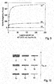
- the FIG. 9 shows the temporal dependence of the fault height H as a function of the storage time in a warm and humid climate at 40 ° C and 95% relative humidity.
- the curve K1 shows the course for a water-impermeable coating 4.
- the curve K2 shows the course for a coating 4, which allows water to pass unhindered
- the curve K3 shows the time course for a coating with average barrier effect.
- fault level H increases exponentially within the first few hours and reaches a saturation level of about 740 nm after about 100 hours.
- coating 4 which is not a barrier to water no fault can be measured.
- the third coating 4 corresponding to K3 has a coating 4 exhibiting a complete barrier similar temporal faulting behavior.
- the saturation value of the discard height H is about 120 nm.
- a row or a matrix of cracks 6a, 6b, 6c... FIG. 10 with different loads F 6a, F 66, F 6c ... applied.
- the loads F 6a, F 66, F 6c ... of the individual crevices 6a, 6b, 6c ... start at a load F 6a at which the coating 4 is not destroyed and ends at the load F 6i , with which the Coating 4 is destroyed safely.
- the loads F 66, F 6c, F 6d ... F 6h in between are selected such that, starting from a specific load F 6e, a crack 6e is added to the coating.
- the coating 4 is subjected to a load F 6e in such a way that the deflection leads to a layer crack.
- the substrate coating system 1, 4, 12, as described above again placed in the said humid climate and measured after a defined time by means of interferometer.
- the FIG. 11 shows a recorded with an interferometer two-dimensional height profile of the section after the FIG. 10 After exposure of the substrate to a warm, humid climate at 40 ° C and 95% relative humidity.
- the scribe applied to the substrate-coating system 1,4,12 serves as the entry port for moisture that can pick up the substrate 1 ( Figures 3 and 4 ).
- the possibility that the substrate 1 can absorb moisture is created by the substrate 1 being stored for a sufficiently long time in a defined dry climate prior to loading with moisture (conditioning step b)).
- the substrate 1 is now loaded with moisture through the scribe and if the coating 4 has a barrier to moisture, then in the vicinity of the scribe 6 the plastic 2 swells to a certain level, which then occurs with the interferometer as a contour line profile (FIG. Fig. 5 ) or as a section through this contour profile ( Fig. 6 ) can be measured.
- the coating 4, which is located on the substrate 1 is barrier-free with respect to the moisture, ie if the moisture can pass unhindered through it, the substrate 1 swells uniformly at all points (FIG. Fig. 7b )). As a result, no height difference between the scribe 6 and the surroundings can be measured with the interferometer.
- the coating 4 represents a barrier to moisture, more moisture penetrates into the substrate 1 at the location of the score 6, with the result that a significant increase can be measured at the location of the score 6 (FIG. Fig. 8b )).
- Fig. 9 and the load sensitivity such as in Fig. 11 information about the swelling rate, about the strength of the barrier effect of the coating 4 for the medium moisture, about the sensitivity of the substrate coating system 1,4, 12 to the medium moisture and allow to make statements that a real Behavior in daily use correspond (as in the case of eyeglass lenses).
- the FIG. 12 Finally shows an embodiment of an inventive device 20 for determining a barrier effect of a coating 4 on a lens blank 12.
- the device 20 comprises a substrate providing means in the form of a carriage 21 with a support surface 22.
- the carriage 21 is located on a transport device 23 in the form of a conveyor belt 24 with a plurality of slides 25, 26, 27 in order to be able to feed the carriage 21 from the conveyor belt 24 to different treatment and measuring devices and from there back to the conveyor belt 24 again.
- the different treatment and measuring devices include a conditioning device in the form of a climatic chamber 28, a diamond trimming tool 29 and an interferometer 30.
- the device 20 further comprises one in the FIG. 12 not shown electronic control device to control the transport device 24 and the functionality of the other components, namely the climatic chamber 28, the Diamantritztechnikmaschines 29 and the interferometer 30.
- the device 20 can be operated in the manner described below:
- a lens blank 12 is provided on the support surface 22 of the carriage 21.
- the lens blank 12 comprises a provided with a coating 4 substrate 1, which changes its volume on contact with water or water vapor.
- the slide 25 pushes the lens blank 12 into the climate chamber 28.
- the climate chamber 28 takes place according to the inventive process step b) conditioning the lens blank 12 in the manner described above by exposure to a standard of 23 ° C and 50% relative humidity for 72 hours.
- the lens blank 12 is conveyed back to the transport device 23 by means of the slider 25.
- the carriage 21 is then moved to the slider 27.
- the slider 27 moves the carriage 21 under the diamond trimming tool 29.
- the lens blank 12 is fixed at its side edge by means of a three-point gripper 31.
- the coating 4 is removed from a first partial surface of the substrate 1.
- the three-point gripper 31 then sets the lens blank 12 again on the support surface 22 of the carriage 21 and the slide 27 spends the carriage 21 again on the conveyor belt 24th
- the conveyor belt 24 transports the carriage 21 with the lens blank 12 to the slider 26, which spends the carriage 21 for determining a first height profile in the interferometer 30 (step d)).
- the lens blank 12 is transported back into the climatic chamber 28 in the manner described above.
- the lens blank 12 is exposed to a humid climate of 40 ° C and 90% relative humidity for 10 minutes (step e)).
- a transport to the interferometer 30 takes place with the aid of which, according to step f), a second height profile of the surface of the lens blank 12 in the vicinity of the score 6 is recorded (step f)).
- steps e) and f) are carried out several times until no significant change in the measured height profile can be determined.
Landscapes
- Physics & Mathematics (AREA)
- General Physics & Mathematics (AREA)
- General Health & Medical Sciences (AREA)
- Chemical & Material Sciences (AREA)
- Analytical Chemistry (AREA)
- Biochemistry (AREA)
- Life Sciences & Earth Sciences (AREA)
- Health & Medical Sciences (AREA)
- Immunology (AREA)
- Pathology (AREA)
- Application Of Or Painting With Fluid Materials (AREA)
- Coating Apparatus (AREA)
- Investigating Materials By The Use Of Optical Means Adapted For Particular Applications (AREA)
- Investigating Or Analysing Materials By Optical Means (AREA)
- Surface Treatment Of Glass (AREA)
Claims (15)
- Procédé de détermination de l'effet de barrière d'un revêtement (4) vis-à-vis d'un fluide (16, 17), le procédé comportant les étapes suivantes :a) application du revêtement sur une surface d'un substrat (1) dont le volume se modifie au contact du fluide (16, 17),b) conditionnement du substrat (1) avec le revêtement (4),c) enlèvement du revêtement (4) d'une première partie (6) de la surface du substrat (1), le revêtement (4) restant sur une deuxième partie de la surface du substrat (1), la première partie (6) de la surface présentant dans une première direction une extension (L) limitée par le revêtement (4) qui reste sur la deuxième partie de la surface,d) détermination d'un premier profil de hauteur d'une surface du revêtement (4) sur la deuxième partie de surface et la première partie (6) de la surface du substrat (1) sur un parcours qui suit la première direction,e) exposition de la surface du reste du revêtement (4) et de la première partie (6) de la surface du substrat (1) au fluide (16, 17),f) détermination d'un deuxième profil de hauteur de la surface du revêtement (4) sur la deuxième partie de la surface et la première partie (6) de la surface du substrat (1) sur le parcours qui longe la première direction et/ou détermination d'une première différence (H) du profil de hauteur de la surface du revêtement (4) sur la deuxième partie de la surface et la première partie (6) de la surface du substrat (1) sur le parcours qui longe la première direction par rapport au profil de hauteur déterminé précédemment.
- Procédé selon la revendication 1, caractérisé en ce que l'enlèvement du revêtement (4) à l'étape c) est réalisé à l'aide d'un outil à rayer, en particulier un outil à rayer (7, 29) au diamant qui est guidé le long de la première direction de manière à arracher de la matière.
- Procédé selon l'une des revendications précédentes, caractérisé en ce que la première partie (6) de la surface présente une extension (B) dans une deuxième direction et en ce que l'extension (L) de la première partie (6) de la surface dans la première direction est au moins dix fois plus grande que l'extension (B) de la première partie (6) de la surface dans la deuxième direction.
- Procédé selon l'une des revendications précédentes, caractérisé en ce qu'avant la détermination du premier profil de hauteur à l'étape d), une troisième partie de surface, non identique à la première partie (6) de la surface du substrat (1) mais non dotée du revêtement, est dotée d'une barrière imperméable au fluide (16, 17).
- Procédé selon l'une des revendications précédentes, caractérisé en ce que la détermination du premier profil de hauteur à l'étape d) et/ou la détermination du deuxième profil de hauteur et/ou de la première différence de profil de hauteur à l'étape f) s'effectue à l'aide d'un interféromètre (30).
- Procédé selon l'une des revendications précédentes, caractérisé en ce que la succession des étapes e) et f) est réalisée de manière répétée.
- Procédé selon la revendication 6, caractérisé en ce que la succession des étapes e) et f) est réalisée de manière répétée jusqu'à ce qu'un critère d'interruption soit satisfait.
- Procédé selon la revendication 7, caractérisé en ce qu'au cas où à l'étape f) une première différence (H) du profil de hauteur est déterminée, le critère d'interruption et que la première différence (H) du profil de hauteur est située en dessous d'une valeur de seuil prédéterminée.
- Procédé selon l'une des revendications précédentes, caractérisé en ce que l'enlèvement du revêtement à l'étape c) est réalisé entièrement jusqu'à la surface du substrat (1).
- Procédé selon l'une des revendications 1 à 8, caractérisé en ce que la succession des étapes c) à f) est réalisée plusieurs fois en des emplacements situés les uns à côté des autres, l'enlèvement du revêtement (4) lors des étapes c) étant réalisé dans des mesures différentes lors des opérations réalisées en des emplacements situés à côté les uns des autres.
- Procédé selon la revendication 10, caractérisé en ce que l'enlèvement du revêtement au cours des étapes c) est réalisé lors des opérations locales adjacentes sous des charges différentes.
- Procédé selon l'une des revendications 10 ou 11, caractérisé en ce que l'enlèvement du revêtement (4) lors de l'étape c) lors des opérations réalisées en des emplacements adjacents est réalisé complètement jusqu'à la surface du substrat (1).
- Procédé selon l'une des revendications 10 à 12, caractérisé en ce que l'enlèvement du revêtement (4) lors d'au moins l'une des opérations réalisées en des emplacements adjacents n'est pas réalisé complètement jusqu'à la surface du substrat (1).
- Ensemble (20) de détermination de l'effet de barrière d'un revêtement (4) vis-à-vis d'un fluide (16, 17), l'ensemble comportant les composants suivants :a) un dispositif de préparation (21) qui prépare le revêtement (4) sur un substrat (1) dont le volume se modifie au contact du fluide (16, 17),b) un dispositif de conditionnement (28) qui conditionne le substrat (1) doté du revêtement (4),c) un dispositif d'enlèvement (7, 29) qui enlève le revêtement (4) d'une première partie (6) de la surface du substrat (1) de telle sorte que le revêtement reste sur une deuxième partie de la surface du substrat (1) et qu'ainsi la première partie (6) de la surface présente dans une première direction une extension (L) limitée par le revêtement (4) qui reste sur la deuxième partie de la surface,d) un dispositif de détermination (30) qui détermine un premier profil de hauteur de la surface du revêtement (4) sur la deuxième partie de la surface et la première partie (6) de la surface du substrat (1) sur un parcours qui longe la première direction,e) un dispositif d'exposition (28) qui expose la surface du revêtement (4) qui reste et la première partie (6) de la surface du substrat (1) au fluide (16, 17),f) un dispositif de détermination (30) qui détermine un deuxième profil de hauteur de la surface du revêtement (4) sur la deuxième partie de la surface et la première partie (6) de la surface du substrat (1) sur le parcours qui longe la première direction et/ou qui détermine une première différence (H) de profil de hauteur de la surface du revêtement (4) sur la deuxième partie de la surface et la première partie (6) de la surface du substrat (1) sur le parcours qui longe la première direction, par rapport au profil de hauteur déterminé précédemment.
- Programme informatique doté de codes de programme permettant de mettre en oeuvre toutes les étapes du procédé selon l'une des revendications 1 à 13 dans un dispositif selon la revendication 14 lorsque le programme informatique est chargé sur un ordinateur et/ou est exécuté sur un ordinateur qui commande l'ensemble.
Applications Claiming Priority (2)
| Application Number | Priority Date | Filing Date | Title |
|---|---|---|---|
| DE102014219496.2A DE102014219496B3 (de) | 2014-09-26 | 2014-09-26 | Verfahren und Vorrichtung zur Bestimmung einer Barrierewirkung einer Beschichtung auf einem Substrat |
| PCT/EP2015/071474 WO2016046085A1 (fr) | 2014-09-26 | 2015-09-18 | Procédé et dispositif de détermination d'un effet barrière d'un revêtement sur un substrat |
Publications (2)
| Publication Number | Publication Date |
|---|---|
| EP3111191A1 EP3111191A1 (fr) | 2017-01-04 |
| EP3111191B1 true EP3111191B1 (fr) | 2017-07-19 |
Family
ID=54288753
Family Applications (1)
| Application Number | Title | Priority Date | Filing Date |
|---|---|---|---|
| EP15777886.1A Active EP3111191B1 (fr) | 2014-09-26 | 2015-09-18 | Procédé et dispositif de détermination d'un effet barrière d'un revêtement sur un substrat |
Country Status (8)
| Country | Link |
|---|---|
| US (1) | US9778170B2 (fr) |
| EP (1) | EP3111191B1 (fr) |
| CN (1) | CN106415805B (fr) |
| DE (1) | DE102014219496B3 (fr) |
| ES (1) | ES2643737T3 (fr) |
| MX (1) | MX356165B (fr) |
| PT (1) | PT3111191T (fr) |
| WO (1) | WO2016046085A1 (fr) |
Families Citing this family (3)
| Publication number | Priority date | Publication date | Assignee | Title |
|---|---|---|---|---|
| CN108845427A (zh) * | 2018-07-03 | 2018-11-20 | 张家港康得新光电材料有限公司 | 一种裸眼3d器件的制备方法及系统 |
| US20210088867A1 (en) * | 2019-09-20 | 2021-03-25 | Kinestral Technologies, Inc. | Quality control of an electrochromic device |
| CN115452712B (zh) * | 2022-09-30 | 2024-05-31 | 西安交通大学 | 一种涂层刮削力旋转刮削测试信号分析方法、系统、介质及设备 |
Family Cites Families (7)
| Publication number | Priority date | Publication date | Assignee | Title |
|---|---|---|---|---|
| US5729323A (en) * | 1994-07-29 | 1998-03-17 | Baush & Lomb Incorporated | Light-absorbing and anti-reflective coating for sunglasses |
| DE19519975C1 (de) * | 1995-05-24 | 1996-10-31 | Fraunhofer Ges Forschung | Verfahren zur Prüfung der Feuchtedurchlässigkeit einer dünnen Schicht |
| DE10012446B4 (de) | 2000-03-15 | 2007-06-14 | Tetra Laval Holdings & Finance S.A. | Verfahren zum Messen der Gasdurchlässigkeit einer Beschichtung auf einer Kunststoffwandung und Vorrichtung zur Durchführung des Verfahrens |
| KR20080061889A (ko) * | 2006-12-28 | 2008-07-03 | 제일모직주식회사 | 플라스틱 수지의 내스크래치성 평가 방법 |
| JP2008266578A (ja) * | 2007-03-23 | 2008-11-06 | Sanyo Electric Co Ltd | 光学ポリマー材料及び光学部品 |
| DE102010048088A1 (de) | 2010-10-01 | 2012-04-05 | Carl Zeiss Vision Gmbh | Optische Linse mit kratzfester Entspiegelungsschicht |
| DE102013104846B3 (de) * | 2013-05-10 | 2014-06-05 | Fraunhofer-Gesellschaft zur Förderung der angewandten Forschung e.V. | Verfahren zur Bestimmung der Feuchtedurchlässigkeit einer Beschichtung |
-
2014
- 2014-09-26 DE DE102014219496.2A patent/DE102014219496B3/de not_active Expired - Fee Related
-
2015
- 2015-09-18 ES ES15777886.1T patent/ES2643737T3/es active Active
- 2015-09-18 PT PT157778861T patent/PT3111191T/pt unknown
- 2015-09-18 MX MX2016013755A patent/MX356165B/es active IP Right Grant
- 2015-09-18 WO PCT/EP2015/071474 patent/WO2016046085A1/fr not_active Ceased
- 2015-09-18 CN CN201580017034.4A patent/CN106415805B/zh active Active
- 2015-09-18 EP EP15777886.1A patent/EP3111191B1/fr active Active
-
2017
- 2017-03-27 US US15/470,537 patent/US9778170B2/en active Active
Non-Patent Citations (1)
| Title |
|---|
| None * |
Also Published As
| Publication number | Publication date |
|---|---|
| CN106415805B (zh) | 2019-07-16 |
| ES2643737T3 (es) | 2017-11-24 |
| US20170199112A1 (en) | 2017-07-13 |
| MX356165B (es) | 2018-05-17 |
| WO2016046085A1 (fr) | 2016-03-31 |
| MX2016013755A (es) | 2017-05-04 |
| EP3111191A1 (fr) | 2017-01-04 |
| DE102014219496B3 (de) | 2016-01-21 |
| CN106415805A (zh) | 2017-02-15 |
| PT3111191T (pt) | 2017-09-04 |
| US9778170B2 (en) | 2017-10-03 |
Similar Documents
| Publication | Publication Date | Title |
|---|---|---|
| EP3030508B1 (fr) | Dispositif et procédé de repérage de défauts pour matériaux en bande | |
| EP3111191B1 (fr) | Procédé et dispositif de détermination d'un effet barrière d'un revêtement sur un substrat | |
| EP0201861B1 (fr) | Procédé et dispositif de mesure d'une tension par des moyens optiques | |
| DE4320341A1 (de) | Verfahren zum Abtragen von Deckschichten von Glasbauteilen mit Laserstrahlung und Vorrichtung zur Durchführung des Verfahrens | |
| WO2003040649A1 (fr) | Procede et dispositif de mesure de grandeurs caracteristiques physiques de couches fines optiquement transparentes | |
| EP3314036A1 (fr) | Procédé de revêtement d'une surface d'une bande métallique ainsi que dispositif de revêtement d'une bande métallique | |
| DE102007059886B4 (de) | Verfahren zur Herstellung einer reflexionsmindernden Schicht und optisches Element mit einer reflexionsmindernden Schicht | |
| DE102019210727A1 (de) | Verfahren zum Bestimmen eines Reinigungszustands einer Oberfläche eines Flachprodukts und Flachprodukt | |
| DE4108329C2 (de) | Verfahren zum Bestimmen von Materialparametern, nämlich Dicke, Brechungsindex und Absorptionskoeffizient, einzelner Schichten | |
| DE102013104846B3 (de) | Verfahren zur Bestimmung der Feuchtedurchlässigkeit einer Beschichtung | |
| DE102014217594A1 (de) | Verfahren und Vorrichtung zum Korrigieren einer Abweichung eines in einer Röntgenanlage gemessenen Dickenwerts einer Probe in Bezug zu einem Kalibrierwert | |
| DE10231383A1 (de) | Verfahren zur Bestimmung der Hafteigenschaften von Materialien | |
| EP2024729A1 (fr) | Dispositif de mesure | |
| WO2019145458A1 (fr) | Procédé d'essai permettant de déterminer la résistance aux conditions climatiques d'un revêtement destiné à un substrat et dispositif associé | |
| DE102024128828B3 (de) | Vorrichtung für einen Probenkörper, System und Verwendung | |
| DE1648494A1 (de) | Verfahren und Vorrichtung zur Ermittlung der Haerte von insbesondere aus viskoelastischem Material bestehenden Probekoerpern | |
| DE102019000525A1 (de) | Verfahren zur Messung der Oberflächenspannung mittels Reflektion am kondensierten Tropfen | |
| EP4400833A1 (fr) | Dispositif de détermination de propriétés optiques d'un substrat optiquement transparent et installation de revêtement | |
| DE2837769C2 (de) | Vorrichtung zur Bestimmung der Konzentration biologischer Substanzen in Mehrkomponenten-Systemen | |
| DE102023113553A1 (de) | Interferenzfreie spektrale Reflexionsmessung | |
| EP3199249B1 (fr) | Dispositif destine a tendre un film de revetement, procede d'examen de la surface d'un film de revetement et utilisation du dispositif destine a tendre un film de revetement pour la determination de la surface d'un film de revetement | |
| DE102012206796B4 (de) | Schnittstrecker-Glasplatte und Einrichtung zum Strecken von Probenschnitten | |
| DE102005038251A1 (de) | Kratzschutzfolie für Displays | |
| AT525814A1 (de) | Nachweisverfahren für einen Nachweis einer Vogelschutzfunktion einer Glasoberfläche | |
| WO2011147760A1 (fr) | Identification d'objets |
Legal Events
| Date | Code | Title | Description |
|---|---|---|---|
| PUAI | Public reference made under article 153(3) epc to a published international application that has entered the european phase |
Free format text: ORIGINAL CODE: 0009012 |
|
| STAA | Information on the status of an ep patent application or granted ep patent |
Free format text: STATUS: REQUEST FOR EXAMINATION WAS MADE |
|
| 17P | Request for examination filed |
Effective date: 20160823 |
|
| AK | Designated contracting states |
Kind code of ref document: A1 Designated state(s): AL AT BE BG CH CY CZ DE DK EE ES FI FR GB GR HR HU IE IS IT LI LT LU LV MC MK MT NL NO PL PT RO RS SE SI SK SM TR |
|
| AX | Request for extension of the european patent |
Extension state: BA ME |
|
| GRAP | Despatch of communication of intention to grant a patent |
Free format text: ORIGINAL CODE: EPIDOSNIGR1 |
|
| STAA | Information on the status of an ep patent application or granted ep patent |
Free format text: STATUS: GRANT OF PATENT IS INTENDED |
|
| DAV | Request for validation of the european patent (deleted) | ||
| DAX | Request for extension of the european patent (deleted) | ||
| INTG | Intention to grant announced |
Effective date: 20170228 |
|
| GRAS | Grant fee paid |
Free format text: ORIGINAL CODE: EPIDOSNIGR3 |
|
| GRAA | (expected) grant |
Free format text: ORIGINAL CODE: 0009210 |
|
| STAA | Information on the status of an ep patent application or granted ep patent |
Free format text: STATUS: THE PATENT HAS BEEN GRANTED |
|
| AK | Designated contracting states |
Kind code of ref document: B1 Designated state(s): AL AT BE BG CH CY CZ DE DK EE ES FI FR GB GR HR HU IE IS IT LI LT LU LV MC MK MT NL NO PL PT RO RS SE SI SK SM TR |
|
| REG | Reference to a national code |
Ref country code: GB Ref legal event code: FG4D Free format text: NOT ENGLISH |
|
| REG | Reference to a national code |
Ref country code: CH Ref legal event code: EP |
|
| REG | Reference to a national code |
Ref country code: IE Ref legal event code: FG4D Free format text: LANGUAGE OF EP DOCUMENT: GERMAN |
|
| REG | Reference to a national code |
Ref country code: AT Ref legal event code: REF Ref document number: 910849 Country of ref document: AT Kind code of ref document: T Effective date: 20170815 |
|
| REG | Reference to a national code |
Ref country code: DE Ref legal event code: R096 Ref document number: 502015001480 Country of ref document: DE |
|
| REG | Reference to a national code |
Ref country code: PT Ref legal event code: SC4A Ref document number: 3111191 Country of ref document: PT Date of ref document: 20170904 Kind code of ref document: T Free format text: AVAILABILITY OF NATIONAL TRANSLATION Effective date: 20170829 |
|
| REG | Reference to a national code |
Ref country code: FR Ref legal event code: PLFP Year of fee payment: 3 |
|
| REG | Reference to a national code |
Ref country code: NL Ref legal event code: MP Effective date: 20170719 |
|
| REG | Reference to a national code |
Ref country code: ES Ref legal event code: FG2A Ref document number: 2643737 Country of ref document: ES Kind code of ref document: T3 Effective date: 20171124 |
|
| REG | Reference to a national code |
Ref country code: LT Ref legal event code: MG4D |
|
| REG | Reference to a national code |
Ref country code: HU Ref legal event code: AG4A Ref document number: E033904 Country of ref document: HU |
|
| PG25 | Lapsed in a contracting state [announced via postgrant information from national office to epo] |
Ref country code: FI Free format text: LAPSE BECAUSE OF FAILURE TO SUBMIT A TRANSLATION OF THE DESCRIPTION OR TO PAY THE FEE WITHIN THE PRESCRIBED TIME-LIMIT Effective date: 20170719 Ref country code: NO Free format text: LAPSE BECAUSE OF FAILURE TO SUBMIT A TRANSLATION OF THE DESCRIPTION OR TO PAY THE FEE WITHIN THE PRESCRIBED TIME-LIMIT Effective date: 20171019 Ref country code: HR Free format text: LAPSE BECAUSE OF FAILURE TO SUBMIT A TRANSLATION OF THE DESCRIPTION OR TO PAY THE FEE WITHIN THE PRESCRIBED TIME-LIMIT Effective date: 20170719 Ref country code: LT Free format text: LAPSE BECAUSE OF FAILURE TO SUBMIT A TRANSLATION OF THE DESCRIPTION OR TO PAY THE FEE WITHIN THE PRESCRIBED TIME-LIMIT Effective date: 20170719 Ref country code: SE Free format text: LAPSE BECAUSE OF FAILURE TO SUBMIT A TRANSLATION OF THE DESCRIPTION OR TO PAY THE FEE WITHIN THE PRESCRIBED TIME-LIMIT Effective date: 20170719 Ref country code: NL Free format text: LAPSE BECAUSE OF FAILURE TO SUBMIT A TRANSLATION OF THE DESCRIPTION OR TO PAY THE FEE WITHIN THE PRESCRIBED TIME-LIMIT Effective date: 20170719 |
|
| PG25 | Lapsed in a contracting state [announced via postgrant information from national office to epo] |
Ref country code: PL Free format text: LAPSE BECAUSE OF FAILURE TO SUBMIT A TRANSLATION OF THE DESCRIPTION OR TO PAY THE FEE WITHIN THE PRESCRIBED TIME-LIMIT Effective date: 20170719 Ref country code: BG Free format text: LAPSE BECAUSE OF FAILURE TO SUBMIT A TRANSLATION OF THE DESCRIPTION OR TO PAY THE FEE WITHIN THE PRESCRIBED TIME-LIMIT Effective date: 20171019 Ref country code: IS Free format text: LAPSE BECAUSE OF FAILURE TO SUBMIT A TRANSLATION OF THE DESCRIPTION OR TO PAY THE FEE WITHIN THE PRESCRIBED TIME-LIMIT Effective date: 20171119 Ref country code: GR Free format text: LAPSE BECAUSE OF FAILURE TO SUBMIT A TRANSLATION OF THE DESCRIPTION OR TO PAY THE FEE WITHIN THE PRESCRIBED TIME-LIMIT Effective date: 20171020 Ref country code: RS Free format text: LAPSE BECAUSE OF FAILURE TO SUBMIT A TRANSLATION OF THE DESCRIPTION OR TO PAY THE FEE WITHIN THE PRESCRIBED TIME-LIMIT Effective date: 20170719 Ref country code: LV Free format text: LAPSE BECAUSE OF FAILURE TO SUBMIT A TRANSLATION OF THE DESCRIPTION OR TO PAY THE FEE WITHIN THE PRESCRIBED TIME-LIMIT Effective date: 20170719 |
|
| REG | Reference to a national code |
Ref country code: DE Ref legal event code: R097 Ref document number: 502015001480 Country of ref document: DE |
|
| PG25 | Lapsed in a contracting state [announced via postgrant information from national office to epo] |
Ref country code: DK Free format text: LAPSE BECAUSE OF FAILURE TO SUBMIT A TRANSLATION OF THE DESCRIPTION OR TO PAY THE FEE WITHIN THE PRESCRIBED TIME-LIMIT Effective date: 20170719 |
|
| PLBE | No opposition filed within time limit |
Free format text: ORIGINAL CODE: 0009261 |
|
| STAA | Information on the status of an ep patent application or granted ep patent |
Free format text: STATUS: NO OPPOSITION FILED WITHIN TIME LIMIT |
|
| PG25 | Lapsed in a contracting state [announced via postgrant information from national office to epo] |
Ref country code: SK Free format text: LAPSE BECAUSE OF FAILURE TO SUBMIT A TRANSLATION OF THE DESCRIPTION OR TO PAY THE FEE WITHIN THE PRESCRIBED TIME-LIMIT Effective date: 20170719 Ref country code: SM Free format text: LAPSE BECAUSE OF FAILURE TO SUBMIT A TRANSLATION OF THE DESCRIPTION OR TO PAY THE FEE WITHIN THE PRESCRIBED TIME-LIMIT Effective date: 20170719 Ref country code: EE Free format text: LAPSE BECAUSE OF FAILURE TO SUBMIT A TRANSLATION OF THE DESCRIPTION OR TO PAY THE FEE WITHIN THE PRESCRIBED TIME-LIMIT Effective date: 20170719 Ref country code: MC Free format text: LAPSE BECAUSE OF FAILURE TO SUBMIT A TRANSLATION OF THE DESCRIPTION OR TO PAY THE FEE WITHIN THE PRESCRIBED TIME-LIMIT Effective date: 20170719 |
|
| 26N | No opposition filed |
Effective date: 20180420 |
|
| REG | Reference to a national code |
Ref country code: IE Ref legal event code: MM4A |
|
| PG25 | Lapsed in a contracting state [announced via postgrant information from national office to epo] |
Ref country code: LU Free format text: LAPSE BECAUSE OF NON-PAYMENT OF DUE FEES Effective date: 20170918 |
|
| PG25 | Lapsed in a contracting state [announced via postgrant information from national office to epo] |
Ref country code: IE Free format text: LAPSE BECAUSE OF NON-PAYMENT OF DUE FEES Effective date: 20170918 |
|
| PG25 | Lapsed in a contracting state [announced via postgrant information from national office to epo] |
Ref country code: SI Free format text: LAPSE BECAUSE OF FAILURE TO SUBMIT A TRANSLATION OF THE DESCRIPTION OR TO PAY THE FEE WITHIN THE PRESCRIBED TIME-LIMIT Effective date: 20170719 |
|
| REG | Reference to a national code |
Ref country code: FR Ref legal event code: PLFP Year of fee payment: 4 |
|
| PG25 | Lapsed in a contracting state [announced via postgrant information from national office to epo] |
Ref country code: MT Free format text: LAPSE BECAUSE OF FAILURE TO SUBMIT A TRANSLATION OF THE DESCRIPTION OR TO PAY THE FEE WITHIN THE PRESCRIBED TIME-LIMIT Effective date: 20170719 |
|
| REG | Reference to a national code |
Ref country code: CH Ref legal event code: PL |
|
| PG25 | Lapsed in a contracting state [announced via postgrant information from national office to epo] |
Ref country code: CH Free format text: LAPSE BECAUSE OF NON-PAYMENT OF DUE FEES Effective date: 20180930 Ref country code: RO Free format text: LAPSE BECAUSE OF FAILURE TO SUBMIT A TRANSLATION OF THE DESCRIPTION OR TO PAY THE FEE WITHIN THE PRESCRIBED TIME-LIMIT Effective date: 20170719 Ref country code: LI Free format text: LAPSE BECAUSE OF NON-PAYMENT OF DUE FEES Effective date: 20180930 |
|
| PG25 | Lapsed in a contracting state [announced via postgrant information from national office to epo] |
Ref country code: CY Free format text: LAPSE BECAUSE OF FAILURE TO SUBMIT A TRANSLATION OF THE DESCRIPTION OR TO PAY THE FEE WITHIN THE PRESCRIBED TIME-LIMIT Effective date: 20170719 |
|
| PG25 | Lapsed in a contracting state [announced via postgrant information from national office to epo] |
Ref country code: MK Free format text: LAPSE BECAUSE OF FAILURE TO SUBMIT A TRANSLATION OF THE DESCRIPTION OR TO PAY THE FEE WITHIN THE PRESCRIBED TIME-LIMIT Effective date: 20170719 |
|
| PG25 | Lapsed in a contracting state [announced via postgrant information from national office to epo] |
Ref country code: TR Free format text: LAPSE BECAUSE OF FAILURE TO SUBMIT A TRANSLATION OF THE DESCRIPTION OR TO PAY THE FEE WITHIN THE PRESCRIBED TIME-LIMIT Effective date: 20170719 |
|
| PG25 | Lapsed in a contracting state [announced via postgrant information from national office to epo] |
Ref country code: AL Free format text: LAPSE BECAUSE OF FAILURE TO SUBMIT A TRANSLATION OF THE DESCRIPTION OR TO PAY THE FEE WITHIN THE PRESCRIBED TIME-LIMIT Effective date: 20170719 |
|
| REG | Reference to a national code |
Ref country code: AT Ref legal event code: MM01 Ref document number: 910849 Country of ref document: AT Kind code of ref document: T Effective date: 20200918 |
|
| PG25 | Lapsed in a contracting state [announced via postgrant information from national office to epo] |
Ref country code: AT Free format text: LAPSE BECAUSE OF NON-PAYMENT OF DUE FEES Effective date: 20200918 |
|
| PGFP | Annual fee paid to national office [announced via postgrant information from national office to epo] |
Ref country code: PT Payment date: 20250904 Year of fee payment: 11 |
|
| PGFP | Annual fee paid to national office [announced via postgrant information from national office to epo] |
Ref country code: DE Payment date: 20250919 Year of fee payment: 11 |
|
| PGFP | Annual fee paid to national office [announced via postgrant information from national office to epo] |
Ref country code: IT Payment date: 20250923 Year of fee payment: 11 |
|
| PGFP | Annual fee paid to national office [announced via postgrant information from national office to epo] |
Ref country code: HU Payment date: 20250922 Year of fee payment: 11 Ref country code: BE Payment date: 20250918 Year of fee payment: 11 Ref country code: GB Payment date: 20250919 Year of fee payment: 11 |
|
| PGFP | Annual fee paid to national office [announced via postgrant information from national office to epo] |
Ref country code: FR Payment date: 20250922 Year of fee payment: 11 |
|
| PGFP | Annual fee paid to national office [announced via postgrant information from national office to epo] |
Ref country code: CZ Payment date: 20250908 Year of fee payment: 11 |
|
| PGFP | Annual fee paid to national office [announced via postgrant information from national office to epo] |
Ref country code: ES Payment date: 20251028 Year of fee payment: 11 |