EP3112859B1 - Porte-échantillon d'un dispositif d'analyse pour l'analyse élémentaire, et dispositif d'analyse pour l'analyse élémentaire - Google Patents
Porte-échantillon d'un dispositif d'analyse pour l'analyse élémentaire, et dispositif d'analyse pour l'analyse élémentaire Download PDFInfo
- Publication number
- EP3112859B1 EP3112859B1 EP16175981.6A EP16175981A EP3112859B1 EP 3112859 B1 EP3112859 B1 EP 3112859B1 EP 16175981 A EP16175981 A EP 16175981A EP 3112859 B1 EP3112859 B1 EP 3112859B1
- Authority
- EP
- European Patent Office
- Prior art keywords
- plate
- hole
- perforated
- sample
- field plate
- Prior art date
- Legal status (The legal status is an assumption and is not a legal conclusion. Google has not performed a legal analysis and makes no representation as to the accuracy of the status listed.)
- Active
Links
Images



Classifications
-
- G—PHYSICS
- G01—MEASURING; TESTING
- G01N—INVESTIGATING OR ANALYSING MATERIALS BY DETERMINING THEIR CHEMICAL OR PHYSICAL PROPERTIES
- G01N31/00—Investigating or analysing non-biological materials by the use of the chemical methods specified in the subgroup; Apparatus specially adapted for such methods
- G01N31/12—Investigating or analysing non-biological materials by the use of the chemical methods specified in the subgroup; Apparatus specially adapted for such methods using combustion
-
- G—PHYSICS
- G01—MEASURING; TESTING
- G01N—INVESTIGATING OR ANALYSING MATERIALS BY DETERMINING THEIR CHEMICAL OR PHYSICAL PROPERTIES
- G01N25/00—Investigating or analyzing materials by the use of thermal means
- G01N25/20—Investigating or analyzing materials by the use of thermal means by investigating the development of heat, i.e. calorimetry, e.g. by measuring specific heat, by measuring thermal conductivity
- G01N25/22—Investigating or analyzing materials by the use of thermal means by investigating the development of heat, i.e. calorimetry, e.g. by measuring specific heat, by measuring thermal conductivity on combustion or catalytic oxidation, e.g. of components of gas mixtures
-
- B—PERFORMING OPERATIONS; TRANSPORTING
- B01—PHYSICAL OR CHEMICAL PROCESSES OR APPARATUS IN GENERAL
- B01L—CHEMICAL OR PHYSICAL LABORATORY APPARATUS FOR GENERAL USE
- B01L3/00—Containers or dishes for laboratory use, e.g. laboratory glassware; Droppers
- B01L3/50—Containers for the purpose of retaining a material to be analysed, e.g. test tubes
- B01L3/502—Containers for the purpose of retaining a material to be analysed, e.g. test tubes with fluid transport, e.g. in multi-compartment structures
-
- B—PERFORMING OPERATIONS; TRANSPORTING
- B01—PHYSICAL OR CHEMICAL PROCESSES OR APPARATUS IN GENERAL
- B01L—CHEMICAL OR PHYSICAL LABORATORY APPARATUS FOR GENERAL USE
- B01L3/00—Containers or dishes for laboratory use, e.g. laboratory glassware; Droppers
- B01L3/50—Containers for the purpose of retaining a material to be analysed, e.g. test tubes
- B01L3/508—Rigid containers without fluid transport within
- B01L3/5085—Rigid containers without fluid transport within for multiple samples, e.g. microtitration plates
-
- G—PHYSICS
- G01—MEASURING; TESTING
- G01N—INVESTIGATING OR ANALYSING MATERIALS BY DETERMINING THEIR CHEMICAL OR PHYSICAL PROPERTIES
- G01N35/00—Automatic analysis not limited to methods or materials provided for in any single one of groups G01N1/00 - G01N33/00; Handling materials therefor
- G01N35/00029—Automatic analysis not limited to methods or materials provided for in any single one of groups G01N1/00 - G01N33/00; Handling materials therefor provided with flat sample substrates, e.g. slides
-
- G—PHYSICS
- G01—MEASURING; TESTING
- G01N—INVESTIGATING OR ANALYSING MATERIALS BY DETERMINING THEIR CHEMICAL OR PHYSICAL PROPERTIES
- G01N35/00—Automatic analysis not limited to methods or materials provided for in any single one of groups G01N1/00 - G01N33/00; Handling materials therefor
- G01N35/00584—Control arrangements for automatic analysers
- G01N35/00722—Communications; Identification
-
- G—PHYSICS
- G01—MEASURING; TESTING
- G01N—INVESTIGATING OR ANALYSING MATERIALS BY DETERMINING THEIR CHEMICAL OR PHYSICAL PROPERTIES
- G01N35/00—Automatic analysis not limited to methods or materials provided for in any single one of groups G01N1/00 - G01N33/00; Handling materials therefor
- G01N35/02—Automatic analysis not limited to methods or materials provided for in any single one of groups G01N1/00 - G01N33/00; Handling materials therefor using a plurality of sample containers moved by a conveyor system past one or more treatment or analysis stations
- G01N35/026—Automatic analysis not limited to methods or materials provided for in any single one of groups G01N1/00 - G01N33/00; Handling materials therefor using a plurality of sample containers moved by a conveyor system past one or more treatment or analysis stations having blocks or racks of reaction cells or cuvettes
-
- G—PHYSICS
- G01—MEASURING; TESTING
- G01N—INVESTIGATING OR ANALYSING MATERIALS BY DETERMINING THEIR CHEMICAL OR PHYSICAL PROPERTIES
- G01N35/00—Automatic analysis not limited to methods or materials provided for in any single one of groups G01N1/00 - G01N33/00; Handling materials therefor
- G01N35/02—Automatic analysis not limited to methods or materials provided for in any single one of groups G01N1/00 - G01N33/00; Handling materials therefor using a plurality of sample containers moved by a conveyor system past one or more treatment or analysis stations
- G01N35/04—Details of the conveyor system
-
- G—PHYSICS
- G01—MEASURING; TESTING
- G01N—INVESTIGATING OR ANALYSING MATERIALS BY DETERMINING THEIR CHEMICAL OR PHYSICAL PROPERTIES
- G01N35/00—Automatic analysis not limited to methods or materials provided for in any single one of groups G01N1/00 - G01N33/00; Handling materials therefor
- G01N35/10—Devices for transferring samples or any liquids to, in, or from, the analysis apparatus, e.g. suction devices, injection devices
- G01N35/1081—Devices for transferring samples or any liquids to, in, or from, the analysis apparatus, e.g. suction devices, injection devices characterised by the means for relatively moving the transfer device and the containers in an horizontal plane
- G01N35/109—Devices for transferring samples or any liquids to, in, or from, the analysis apparatus, e.g. suction devices, injection devices characterised by the means for relatively moving the transfer device and the containers in an horizontal plane with two horizontal degrees of freedom
-
- B—PERFORMING OPERATIONS; TRANSPORTING
- B01—PHYSICAL OR CHEMICAL PROCESSES OR APPARATUS IN GENERAL
- B01L—CHEMICAL OR PHYSICAL LABORATORY APPARATUS FOR GENERAL USE
- B01L2200/00—Solutions for specific problems relating to chemical or physical laboratory apparatus
- B01L2200/02—Adapting objects or devices to another
- B01L2200/025—Align devices or objects to ensure defined positions relative to each other
-
- B—PERFORMING OPERATIONS; TRANSPORTING
- B01—PHYSICAL OR CHEMICAL PROCESSES OR APPARATUS IN GENERAL
- B01L—CHEMICAL OR PHYSICAL LABORATORY APPARATUS FOR GENERAL USE
- B01L2200/00—Solutions for specific problems relating to chemical or physical laboratory apparatus
- B01L2200/02—Adapting objects or devices to another
- B01L2200/026—Fluid interfacing between devices or objects, e.g. connectors, inlet details
-
- B—PERFORMING OPERATIONS; TRANSPORTING
- B01—PHYSICAL OR CHEMICAL PROCESSES OR APPARATUS IN GENERAL
- B01L—CHEMICAL OR PHYSICAL LABORATORY APPARATUS FOR GENERAL USE
- B01L2200/00—Solutions for specific problems relating to chemical or physical laboratory apparatus
- B01L2200/14—Process control and prevention of errors
-
- B—PERFORMING OPERATIONS; TRANSPORTING
- B01—PHYSICAL OR CHEMICAL PROCESSES OR APPARATUS IN GENERAL
- B01L—CHEMICAL OR PHYSICAL LABORATORY APPARATUS FOR GENERAL USE
- B01L2300/00—Additional constructional details
- B01L2300/06—Auxiliary integrated devices, integrated components
- B01L2300/0627—Sensor or part of a sensor is integrated
-
- B—PERFORMING OPERATIONS; TRANSPORTING
- B01—PHYSICAL OR CHEMICAL PROCESSES OR APPARATUS IN GENERAL
- B01L—CHEMICAL OR PHYSICAL LABORATORY APPARATUS FOR GENERAL USE
- B01L2300/00—Additional constructional details
- B01L2300/06—Auxiliary integrated devices, integrated components
- B01L2300/069—Absorbents; Gels to retain a fluid
-
- B—PERFORMING OPERATIONS; TRANSPORTING
- B01—PHYSICAL OR CHEMICAL PROCESSES OR APPARATUS IN GENERAL
- B01L—CHEMICAL OR PHYSICAL LABORATORY APPARATUS FOR GENERAL USE
- B01L2300/00—Additional constructional details
- B01L2300/08—Geometry, shape and general structure
- B01L2300/0809—Geometry, shape and general structure rectangular shaped
-
- G—PHYSICS
- G01—MEASURING; TESTING
- G01N—INVESTIGATING OR ANALYSING MATERIALS BY DETERMINING THEIR CHEMICAL OR PHYSICAL PROPERTIES
- G01N35/00—Automatic analysis not limited to methods or materials provided for in any single one of groups G01N1/00 - G01N33/00; Handling materials therefor
- G01N35/00029—Automatic analysis not limited to methods or materials provided for in any single one of groups G01N1/00 - G01N33/00; Handling materials therefor provided with flat sample substrates, e.g. slides
- G01N2035/00099—Characterised by type of test elements
-
- G—PHYSICS
- G01—MEASURING; TESTING
- G01N—INVESTIGATING OR ANALYSING MATERIALS BY DETERMINING THEIR CHEMICAL OR PHYSICAL PROPERTIES
- G01N35/00—Automatic analysis not limited to methods or materials provided for in any single one of groups G01N1/00 - G01N33/00; Handling materials therefor
- G01N35/02—Automatic analysis not limited to methods or materials provided for in any single one of groups G01N1/00 - G01N33/00; Handling materials therefor using a plurality of sample containers moved by a conveyor system past one or more treatment or analysis stations
- G01N35/04—Details of the conveyor system
- G01N2035/0401—Sample carriers, cuvettes or reaction vessels
- G01N2035/0418—Plate elements with several rows of samples
-
- G—PHYSICS
- G01—MEASURING; TESTING
- G01N—INVESTIGATING OR ANALYSING MATERIALS BY DETERMINING THEIR CHEMICAL OR PHYSICAL PROPERTIES
- G01N35/00—Automatic analysis not limited to methods or materials provided for in any single one of groups G01N1/00 - G01N33/00; Handling materials therefor
- G01N35/02—Automatic analysis not limited to methods or materials provided for in any single one of groups G01N1/00 - G01N33/00; Handling materials therefor using a plurality of sample containers moved by a conveyor system past one or more treatment or analysis stations
- G01N35/04—Details of the conveyor system
- G01N2035/0401—Sample carriers, cuvettes or reaction vessels
- G01N2035/0418—Plate elements with several rows of samples
- G01N2035/0422—Plate elements with several rows of samples carried on a linear conveyor
- G01N2035/0424—Two or more linear conveyors
-
- G—PHYSICS
- G01—MEASURING; TESTING
- G01N—INVESTIGATING OR ANALYSING MATERIALS BY DETERMINING THEIR CHEMICAL OR PHYSICAL PROPERTIES
- G01N31/00—Investigating or analysing non-biological materials by the use of the chemical methods specified in the subgroup; Apparatus specially adapted for such methods
- G01N31/005—Investigating or analysing non-biological materials by the use of the chemical methods specified in the subgroup; Apparatus specially adapted for such methods investigating the presence of an element by oxidation
Definitions
- the following invention relates to a sample holder of an analysis device for elemental analysis, as for example from the DE 31 16 049 A1 is known.
- the present invention relates to an analytical device for quantitative elemental analysis with such a sample holder.
- it wants to specify an analysis device for elemental analysis for determining the nitrogen content in a sample.
- the DE 31 16 049 A1 discloses a sample holder having a rail with recesses for samples to be inserted.
- This rail rests on a base, which has an ejection opening.
- the rail is bordered on its longitudinal sides by the base, whereby a guide is formed.
- a pneumatic motor moves the rail along this guide and a respective recess is brought into coincidence with the ejection opening.
- the sample then falls through the ejection port and is fed to an analyzer.
- An analysis device for the elemental analysis is for example from the EP 1 586 895 A1 known.
- This analyzer has a sample holder formed by a rotating wheel having a plurality of holes of equal radius distributed around the circumference, which are brought one behind the other via a discharge opening to make the sample accessible for analysis.
- the sample falls from there into a reactor for catalytic combustion.
- oxygen is introduced for the time of combustion.
- the amount of oxygen is automatically calculated according to the weight used and the nature of the sample, it is accordingly stoichiometric.
- a reduction reactor is provided, which serves to reduce the sample.
- an adsorber is provided, which is followed by a detector to determine the content of the elements to be analyzed in the gas stream.
- the detector cooperates with a logic unit, which transmits the data collected by the detector in order to generate a quantitative assessment of the sample with regard to the elementary content based on this data.
- a water trap and / or one or more self-regenerable water absorbers may be provided downstream of the reduction reactor, which carries out water from the gas.
- the gas stream may be provided a device for the regeneration of adsorber elements, which can be removed cyclically from the gas stream and fed to the desorption. This regeneration may be provided outside a housing of an analysis device contained in the elements mentioned in claim 5.
- the regeneration means can also be provided within the housing and adapted for automated desorption, as for example with EP 1 586 895 A1 is taught.
- the present invention aims to further develop the known sample holder of an elemental analysis analyzer. In particular, it wants to improve the sample delivery for the analysis and to specify an improved analysis device.
- Such a sample holder comprises a perforated field plate.
- the perforated field plate has a plurality of holes, usually provided in a predetermined grid to each other.
- the holes are usually formed continuously through the perforated field plate, so as through holes. They are usually cylindrical.
- the grid leads to a formation of an at least first perforated field, in which the holes are usually provided with a constant transverse and longitudinal spacing relative to each other.
- This perforated field plate is movable on a base which is provided with a Abwerfö réelle for discharging a certain sample from a hole of the perforated field plate.
- the ejection opening usually has a diameter which corresponds in terms of shape and size to the diameter of the holes of the perforated field.
- the perforated field plate is translationally free on the pad in a Cartesian X-Y coordinate system movable to spend individual holes of the perforated field plate on the ejection opening and drop the sample there.
- the solution according to the invention makes it possible to fill the perforated field plate with samples from the side opposite the base.
- the solution according to the invention provides a more flexible way of dropping samples into the analytical device for elemental analysis.
- the pad and the mobility of the perforated field plate and the dimension of the perforated field plate can be coordinated so that the perforated field plate can be moved outside the Abwerfö réelle on the substrate, ie, the individual holes of the perforated field plate can be moved past the ejection opening.
- the perforated field plate has a first perforated field and a second perforated field, which are separated from each other by a widened web.
- the first hole field usually has a grid with several adjacent rows of holes. This first hole field is the usual recording of the analyzed Sample.
- the second hole field may comprise few or only a single hole. If a few holes are provided, these holes of the second hole field can be provided with the same longitudinal or transverse distance to each other as the holes of the grid of the first hole field. However, only a single row of holes can form the second hole field.
- the perforated field plate is brought with its web to cover with the Abwerfö réelle and moved along the bridge over the Abwerfö réelle until that position of the second hole field is reached, containing the preferred sample to be analyzed. The hole located at this position is then brought to the Abwerfö réelle to cover.
- the widened ridge usually extends parallel to two mutually parallel rows of holes, one row being associated with the first hole box and the other row being associated with the second hole box.
- the widened web passes from one edge surface to the other edge surface of the perforated field plate.
- the land is broadened, which means that this land is wider than the land between two adjacent rows of holes, for example, the first hole field.
- the web is usually formed so wide that it can completely cover the ejection opening.
- a particularly simple embodiment of the analysis device is specified in accordance with a preferred development of the present invention in that the perforated field plate is held on a traverse, which is movable in a first direction relative to the base.
- the pad is formed in accordance with this preferred embodiment by a base plate which is encompassed by the traverse.
- a drive is preferably provided, which mediates the movement of the perforated field plate by the movement of the traverse in the first direction.
- This drive may for example be a motor that meshes with a rack, which is provided on a base plate engaging around the guide web of the traverse.
- Under the pad usually guide elements are provided which guide the movement of the cross member in the first direction.
- the crosshead also preferably has a self-contained drive which cooperates with a holder for the perforated field plate and moves the perforated field plate along the traverse in a second direction.
- This second direction is the longitudinal direction of the traverse and usually extends transversely to the first direction.
- the movement in the second direction is usually mediated by a gear of a drive and a parallel to the plane of the perforated field plate extending and coupled to the perforated field plate rack.
- a transfer plate is proposed according to a preferred embodiment of the present invention, which is provided with a first at least the first hole field corresponding first transfer hole field.
- This transfer plate is associated with a sliding plate for the underside closure of the transfer plate.
- the slide plate is usually held in a sliding guide of the transfer plate and secured against falling out in the direction of the transfer holes formed on the transfer plate, but slidable in a direction perpendicular thereto.
- the sliding plate closes off the transfer holes recessed in the transfer plate on the underside.
- the transfer plate can first be equipped with samples.
- the transfer plate has interlocking means or other positioning aids to bring the mutual hole fields of transfer plate on the one hand and perforated field plate on the other to overlap.
- the holes of the perforated field plate are usually coded, wherein the coding is preferably provided on the sliding plate, so that the individual positions within the perforated field plate are readable with inserted sliding plate. This facilitates the assignment of the sample to a position within the perforated field plate.
- the transfer plate usually has the same dimensions as the perforated field plate, so that an aligned arrangement of the holes can be effected by simply covering the edges of the mutual perforated plates. Thereafter, the sliding plate between the perforated field plate and the transfer plate is usually pulled out of the sliding guide, so that the samples fall down into the holes of the perforated field plate.
- the analyzer is usually oriented so that the holes of the perforated field plate extend in the vertical direction, so that both the transfer from the transfer plate to the perforated field plate as well as the ejection of the sample in the direction of the reactor Gravity can be done. Contrary to this direction of movement, gas usually also flows out through the ejection opening, so that it is reliably prevented that ambient air with the sample reaches the reactor for the catalytic combustion and falsifies the sample result there.
- the analyzer usually has a valve to switch between an oxygen flow in the line and an inert gas flow, so that sample can be discarded impurity-free with inert gas and then switched to oxygen gas to effect residue-free catalytic combustion.
- the transfer plate can have a perforated field corresponding to the first and the second perforated field and in each case aligned therewith, so that after placement of the transfer plate both samples to be processed in the usual sequence and also samples having higher priority can be charged.
- a sliding piston is provided on the underside of the pad, which is sealingly guided in a Ausschiebezylinder.
- the spool has a receiving bore that regularly has the same axial orientation as the ejection port.
- This receiving bore is cyclically reciprocable between a first position and a second position. In the first position, the receiving bore is aligned with the ejection opening. In the second position, the receiving bore is aligned with a conduit section of the inert gas line, in particular helium, and the oxygen, which usually leads in strictly vertical extent directly to the catalytic combustion reactor.
- the sample ejected from the pad into the ejection port can pass directly to the reactor.
- the sliding piston is usually kept sealed in the Ausschiebezylinder.
- grooves are preferably recessed on the sliding piston immediately adjacent to the receiving bore, hold the sealing rings, which cooperate with the inner peripheral surface of the Ausschiebezylinders.
- the Ausschiebezylinder is usually connected to a source at least for the inert gas to prevent unwanted entry of atmospheric air into the analysis device through the Abwerfö réelle.
- the said ejection cylinder forms a sluice with the slide piston accommodated therein.
- the pad has a shop window.
- This shop window allows the view through the pad on the receiving bore in the second position.
- the shop window seals off the area above the receiving bore, so that an entry of ambient air through the shop window into the receiving bore and to the reactor is avoided.
- the shop window is usually flush with the surface of the pad without heels, so that samples can also be moved over the shop window without parts of the samples getting caught in the area of the shop window.
- a camera is provided, which is directed to the ejection opening and / or the shop window.
- the camera is usually connected to a central logic unit and visually monitors the ejection of the sample through the ejection opening or the transfer of the sample in the second position of the receiving bore in the line section.
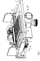
- the Fig. 1 and 2 let recognize the essential parts of the embodiment.
- This comprises a base plate 2, which forms a flat base 4 and the top side carries a traverse 6, which is movable in the direction of the directional arrow X and connected to the base plate 2.
- the cross member has 6 lateral legs 8, which surround the base plate 2 (see. Fig. 2 ).
- There longitudinal guides 10 and a first drive 12 are provided, which meshes via a gear with a first rack 14 which is fixed to one of the legs 8. This is the result Possibility created to move the traverse 6 in a first direction, ie the X-direction relative to the base 4.
- the traverse 6 has a cover 16 which covers a second drive 18 which meshes via a gear with a second rack 20, which is connected to a holder 22 for a perforated field plate 24.
- the traverse 6 forms a transverse guide 26, via which the holder 22 in the second direction, ie the in Fig. 1 drawn Y-direction is movable.
- the two drives 12, 18 are coupled in terms of control with a logic unit which controls the two drives 12, 18 such that the perforated field plate 24 is held or arranged at a predetermined position.
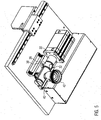
- Fig. 2 shows a designated by reference numeral 28 lock for introducing a sample. Details of this lock 28 are the Fig. 5 refer to.
- the lock 28 has (see. Fig. 5 ) a movable sliding piston 30 which is penetrated by a receiving bore 32 and held displaceably in a Ausschiebezylinder 34.
- the discharge cylinder 34 has an introduction port 36 which is in alignment with a discharge opening 38 recessed in the base plate 2, and a discharge port 40 which is in alignment with a conduit section 42 connected to the discharge cylinder 34 and for sealingly bolting a catalytic combustion reactor, not shown adapted trained.
- the perforated field plate 24 shown has a first perforated field 44 with a plurality of equidistantly spaced rows of holes 46 and a second perforated field 48 formed by a single row of holes 46. Between the two hole fields 44, 48 a widened web 50 is provided.
- the Fig. 4 can also see in the line of sight behind the perforated plate 24, the ejection opening 38 and a marked with reference numeral 52 showcase, which allows the view of the receiving bore 32 in the second position of the sliding piston 30 through the wall of the Ausschiebezylinders 34, in which the receiving bore 32 with the line section 42 is aligned.
- the web 50 has a relation to the intermediate webs between rows of the first hole field 44 greater width.
- the width of the web 50 is chosen so that it slightly surmounted the diameter of the Abwerfö réelle 38 and thus is suitable to cover the Abwerfö réelle 38.
- the Fig. 1 and 3 show the first embodiment together with a transfer plate 54 which is placed in the said figures on the perforated field plate 24.
- the transfer plate 54 has the same dimensions as the perforated field plate 24.
- the transfer plate 54 has first and second transfer hole fields 56, 58, the holes of which are the same pitch as the holes of the first and second hole fields 44, 48 of the perforated field plate 24.
- the perforated field plate 24 holding and connected to the second toothed rail 20 holding arms 60 and a perpendicular thereto extending carrier 62, which are connected to the second drive 18, with a height corresponding to the height of the perforated plate 24 and the transfer plate 54 height provided above the pad 4.
- Fig. 1 further discloses a slide plate 64 provided above the perforated field plate 24 and slidably supported on the transfer plate 54 in a slide guide 66 recessed on the transfer plate 54.
- the sliding plate 64 closes off the holes of the transfer hole fields 56, 58 on the underside.
- the transfer plate 54 may initially be charged at a laboratory location and then placed with the slide plate 64 in position over the perforated field plate 24 and aligned therewith. Thereafter, the slide plate 64 is pulled, whereby the samples each fall from the holes of the transfer plate 54 into the corresponding holes 46 of the hole field plate 24.
- Fig. 3 64 sample positions are inscribed on the upper side of the sliding plate, so that each individual hole of the transfer plate 54 and thus of each individual hole of the perforated field plate 24 are assigned sample positions.
- the sample positions 1 to 64 correspond to the positions of the first hole field.
- These holes 46 have constant transverse and longitudinal spacings, ie constant distances in both the X and Y directions.
- the holes AH are holes of the second hole field 2, which are provided only in the X direction one behind the other, but there with the spacing of the holes 46 of the first hole field 44th
- the transfer plate 54 is lifted up to feed it again while performing the automated analysis by the embodiment.
- the drives 12 and 18 are operated in a controlled manner in order to bring the perforated field plate 24 with a selected hole 46 via the ejection opening 38. This will eject the sample from the corresponding hole 46, in the receiving bore 32 of the spool 30, which is in the first position.
- the sliding piston 30 is displaced in the Ausschiebezylinder 34, so that the receiving bore 32 is aligned with the line section 42. Due to gravity, the sample is thus dropped through the discharge opening 40 in the line section 42 and thus the reactor for the catalytic combustion.
- the sample is burned in a conventional manner with the addition of oxygen.
- the combustion gases are treated to separate, for example, water. Thereafter, the combustion gases are supplied to the adsorber, so that the ingredients of interest for the analysis can be separated and measured by the detector.
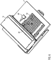
- the Fig. 6 shows an alternative embodiment with a camera 68, which is provided above the pad 4 and in the field of view, both the ejection opening 38 as well as the shop window 52 is located.
- the camera 68 is usually provided in the axial extension of the axis of the shop window 52 and thus can also detect the line section 42 optically.
- the camera 68 is connected to the central logic unit. It can detect both the ejection of the sample from the perforated field plate 24 through the ejection opening 38, as well as the ejection of the sample from the receiving bore 32 in the line section 42nd
- a gas line is connected, through which inert gas, such as helium, can be introduced into the interior of the Ausschiebezylinders 34.
- inert gas such as helium
- the further path of the sample from the conduit section 42 is in Fig. 7 shown schematically.
- the sample falls into a reactor UR for catalytic combustion.
- the resulting gases are fed to a reduction reactor RR.
- water contained in the combustion gas H 2 O is adsorbed.
- CO 2 contained in the gas is then removed from the gas.
- the nitrogen content is measured (at WLD) and the measured value is analyzed and output via a computer (PC).
- the in Fig. 7 The frame marked with reference numeral 70 illustrates those elements of the analysis device that are located within a housing, wherein on the top of the housing 70 of the Ausschiebezylinder 34 with the previously with reference to the FIGS. 1 to 6 is provided sample holder described, wherein the sample holder is only schematically indicated by a perforated disc (72).
Landscapes
- Chemical & Material Sciences (AREA)
- Health & Medical Sciences (AREA)
- Analytical Chemistry (AREA)
- General Health & Medical Sciences (AREA)
- Life Sciences & Earth Sciences (AREA)
- Biochemistry (AREA)
- Physics & Mathematics (AREA)
- General Physics & Mathematics (AREA)
- Immunology (AREA)
- Pathology (AREA)
- Chemical Kinetics & Catalysis (AREA)
- Combustion & Propulsion (AREA)
- Engineering & Computer Science (AREA)
- Hematology (AREA)
- Clinical Laboratory Science (AREA)
- Molecular Biology (AREA)
- Investigating Or Analyzing Non-Biological Materials By The Use Of Chemical Means (AREA)
Claims (8)
- Porte-échantillons d'un appareil d'analyse pour l'analyse élémentaire, comportant une platine à zone de trous (24), qui est mobile, au moyen d'un entraînement (12, 18), sur un support d'appui (4) pourvu d'une ouverture d'éjection (38) pour l'éjection d'un échantillon, caractérisé en ce que la platine à zone de trous (24) est librement déplaçable en translation sur le support d'appui (4), dans un système de coordonnées cartésien X-Y.
- Porte-échantillons selon la revendication 1, caractérisé en ce que la platine à zone de trous (24) comprend une première zone de trous (44) et une deuxième zone de trous (48), qui sont séparées l'une de l'autre par l'intermédiaire d'une nervure (50), qui est plus large qu'une nervure entre deux rangées voisines de trous de la première zone de trous (44).
- Porte-échantillons selon la revendication 1 ou la revendication 2, caractérisé en ce que la platine à zone de trous (24) est maintenue sur une traverse (6), qui entoure une plaque de base (2) formant le support d'appui (4) et est mobile dans une première direction (X) par rapport à ladite plaque de base (2), et est maintenue coulissante par rapport à la traverse (6) dans la direction longitudinale de celle-ci.
- Porte-échantillons selon la revendication 2, caractérisé par une plaque de transfert (54), qui est pourvue d'une première zone de trous de transfert (56, 58) en correspondance avec au moins ladite première zone de trous (44), et à laquelle est associée une plaque coulissante (64) assurant la fermeture du côté inférieur de la plaque de transfert (54) et pouvant, après l'application de la plaque de transfert (54) sur la platine à zone de trous (24), être retirée de l'espace entre la platine à zone de trous et la plaque de transfert.
- Appareil d'analyse pour l'analyse élémentaire comprenant un porte-échantillons selon l'une des revendications précédentes, une conduite (70) pour de l'oxygène et du gaz inerte, un réacteur pour la combustion catalytique d'un échantillon, un réacteur de réduction prévu en aval dudit réacteur de combustion, un adsorbeur prévu en aval du réacteur de réduction, un détecteur prévu en aval de l'adsorbeur, et une unité logique pour assurer le traitement des données transmises par le détecteur.
- Appareil d'analyse selon la revendication 5, caractérisé par un piston coulissant (30) prévu sur le côté inférieur du support d'appui (4), guidé de manière étanche dans un cylindre d'extraction (34) et comportant un alésage de réception (32), qui est mobile de manière cyclique entre une première position dans laquelle l'alésage de réception (32) est agencé en alignement avec l'ouverture d'éjection (38), et une deuxième position dans laquelle l'alésage de réception (32) est agencé en alignement avec un tronçon de conduite (42) de la conduite, qui mène au réacteur.
- Appareil d'analyse selon la revendication 6, caractérisé par un hublot d'observation (52) dégagé dans le support d'appui (4) pour vérifier la position de l'alésage de réception (32) dans ladite deuxième position.
- Appareil d'analyse selon l'une des revendications 5 à 7, caractérisé par une caméra (68) dirigée sur l'ouverture d'éjection (38) et/ou le hublot d'observation (52).
Applications Claiming Priority (1)
| Application Number | Priority Date | Filing Date | Title |
|---|---|---|---|
| DE202015004524.3U DE202015004524U1 (de) | 2015-06-24 | 2015-06-24 | Analyseeinrichtung für die Elementaranalyse |
Publications (2)
| Publication Number | Publication Date |
|---|---|
| EP3112859A1 EP3112859A1 (fr) | 2017-01-04 |
| EP3112859B1 true EP3112859B1 (fr) | 2018-01-24 |
Family
ID=56551124
Family Applications (1)
| Application Number | Title | Priority Date | Filing Date |
|---|---|---|---|
| EP16175981.6A Active EP3112859B1 (fr) | 2015-06-24 | 2016-06-23 | Porte-échantillon d'un dispositif d'analyse pour l'analyse élémentaire, et dispositif d'analyse pour l'analyse élémentaire |
Country Status (5)
| Country | Link |
|---|---|
| US (1) | US10274442B2 (fr) |
| EP (1) | EP3112859B1 (fr) |
| JP (1) | JP6312747B2 (fr) |
| DE (1) | DE202015004524U1 (fr) |
| DK (1) | DK3112859T3 (fr) |
Cited By (2)
| Publication number | Priority date | Publication date | Assignee | Title |
|---|---|---|---|---|
| EP4276340A1 (fr) | 2022-05-12 | 2023-11-15 | C. Gerhardt GmbH & Co. KG | Dispositif d'analyse pour l'analyse élémentaire |
| EP4276458A1 (fr) | 2022-05-12 | 2023-11-15 | C. Gerhardt GmbH & Co. KG | Dispositif d'analyse pour l'analyse élémentaire |
Families Citing this family (4)
| Publication number | Priority date | Publication date | Assignee | Title |
|---|---|---|---|---|
| EP3704493B1 (fr) * | 2018-01-26 | 2024-07-03 | Hewlett-Packard Development Company, L.P. | Plates-formes de distributeur |
| RU184021U1 (ru) * | 2018-07-31 | 2018-10-11 | Леонид Владимирович Илясов | Термохимический детектор газов |
| CN110164748B (zh) * | 2019-06-21 | 2025-02-07 | 中国科学技术大学 | 一种进样装置 |
| EP4299159A1 (fr) * | 2022-06-27 | 2024-01-03 | C. Gerhardt GmbH & Co. KG | Dispositif d'adsorption destiné à l'adsorption du co2, appareil d'analyse élémentaire et procédé d'élimination du co2 d'un écoulement de fluide |
Family Cites Families (15)
| Publication number | Priority date | Publication date | Assignee | Title |
|---|---|---|---|---|
| JPS597069B2 (ja) | 1976-02-16 | 1984-02-16 | 日立金属株式会社 | バタフライ弁 |
| DE2730214A1 (de) * | 1977-07-04 | 1979-01-11 | Franz Liebl | Mehrfachprobenstaender fuer labor- untersuchungen |
| IT1122396B (it) | 1979-08-02 | 1986-04-23 | Erba Strumentazione | Campionatore per sistemi analitici di rilevazione |
| DE3116049A1 (de) * | 1981-04-22 | 1982-11-11 | Antek Instruments GmbH, 4000 Düsseldorf | Verbrennungsapparat fuer die elementaranalyse |
| FR2560686B1 (fr) * | 1984-03-05 | 1986-11-07 | Rhone Poulenc Rech | Appareil de mineralisation pour le traitement individuel, de facon automatique, d'echantillons de produits places dans des recipients |
| US4731335A (en) | 1985-09-13 | 1988-03-15 | Fisher Scientific Company | Method for treating thin samples on a surface employing capillary flow |
| JP2529725B2 (ja) | 1988-10-05 | 1996-09-04 | 倉敷紡績株式会社 | テ―ブル移動装置 |
| JP2949501B2 (ja) | 1989-03-29 | 1999-09-13 | 株式会社 堀場製作所 | 試料の分析用ガス抽出装置 |
| IT1256355B (it) * | 1992-08-31 | 1995-12-01 | Procedimento e apparecchiatura per la determinazione dell'azoto totale mediante analisi elementare | |
| IT1256356B (it) | 1992-08-31 | 1995-12-01 | Dispositivo per l'alimentazione di campioni ad apparecchiature di analisi elementare | |
| US5314662A (en) * | 1993-03-08 | 1994-05-24 | Leco Corporation | Sample autoloader for use with an analytical combustion furnace |
| US5866072A (en) * | 1996-02-26 | 1999-02-02 | Cds Analytical, Inc. | Analytical pyrolysis autosampler |
| JP3062952U (ja) | 1999-04-09 | 1999-10-15 | 有限会社光信理化学製作所 | ガス発生抽出装置 |
| JP3878667B2 (ja) | 2002-09-17 | 2007-02-07 | シーケーディ株式会社 | 分注システム |
| ITMI20040740A1 (it) * | 2004-04-15 | 2004-07-15 | Ecoenergetics S R L | Analizzatore automatico per la rilevazione di azoto proveniente da composti organici |
-
2015
- 2015-06-24 DE DE202015004524.3U patent/DE202015004524U1/de not_active Expired - Lifetime
-
2016
- 2016-06-23 EP EP16175981.6A patent/EP3112859B1/fr active Active
- 2016-06-23 DK DK16175981.6T patent/DK3112859T3/en active
- 2016-06-24 JP JP2016125289A patent/JP6312747B2/ja active Active
- 2016-06-24 US US15/191,926 patent/US10274442B2/en active Active
Non-Patent Citations (1)
| Title |
|---|
| None * |
Cited By (2)
| Publication number | Priority date | Publication date | Assignee | Title |
|---|---|---|---|---|
| EP4276340A1 (fr) | 2022-05-12 | 2023-11-15 | C. Gerhardt GmbH & Co. KG | Dispositif d'analyse pour l'analyse élémentaire |
| EP4276458A1 (fr) | 2022-05-12 | 2023-11-15 | C. Gerhardt GmbH & Co. KG | Dispositif d'analyse pour l'analyse élémentaire |
Also Published As
| Publication number | Publication date |
|---|---|
| US20160377563A1 (en) | 2016-12-29 |
| JP6312747B2 (ja) | 2018-04-18 |
| JP2017009613A (ja) | 2017-01-12 |
| EP3112859A1 (fr) | 2017-01-04 |
| DK3112859T3 (en) | 2018-04-30 |
| DE202015004524U1 (de) | 2016-09-29 |
| US10274442B2 (en) | 2019-04-30 |
Similar Documents
| Publication | Publication Date | Title |
|---|---|---|
| EP3112859B1 (fr) | Porte-échantillon d'un dispositif d'analyse pour l'analyse élémentaire, et dispositif d'analyse pour l'analyse élémentaire | |
| DE69308957T2 (de) | Verfahren und Vorrichtung zur Handhabung von Proben | |
| EP1110609B1 (fr) | Système de traitement d'échantillons dans un dispositif à compartiments multiples | |
| EP1628894B1 (fr) | Section de transporteur pourvue d'un rail ajustable, et mecanisme d'actionnement | |
| DE3042915A1 (de) | Verfahren und vorrichtung zur automatischen analyse von fluidproben | |
| EP2702386B1 (fr) | Dispositif de poinçonnage pourvu d'une unité de préhension | |
| DE2602370A1 (de) | Verfahren und vorrichtung zum erzeugen von mikrospaerischen teilchen | |
| DE2245711A1 (de) | Verfahren und vorrichtung zum ruehren eines probenmaterials | |
| DE102006015535A1 (de) | Verfahren und Vorrichtung zur Analyse von Isotopenverhältnissen | |
| DE3047265C2 (de) | Einrichtung zur Überführung von Probengefäßen in Auffanggefäße | |
| DE3835207C1 (fr) | ||
| DE60225968T2 (de) | Vorrichtung und Verfahren zur Bereitstellung von Bodenproben | |
| DE10043345C2 (de) | Vorrichtung zur vollautomatischen Festphasenextraktion | |
| DE4009993C2 (fr) | ||
| DE3028818C2 (fr) | ||
| EP0534096A2 (fr) | Procédé et dispositif pour examiner des impuretés dans des récipients | |
| DE102011000891A1 (de) | Verfahren und Vorrichtung zum Bestimmen mindestens einer Veränderlichen | |
| DE112017005675T5 (de) | System zum Durchführen chemischer, biologischer und/oder medizinischer Prozesse | |
| DE2543012C3 (fr) | ||
| EP3673263B1 (fr) | Procédé de fourniture d'une quantité de substance | |
| DE2357062C2 (de) | Verfahren und Vorrichtung zum Entnehmen einer Probe aus einer Förderleitung | |
| AT527682B1 (de) | Haltevorrichtung | |
| DE602005002881T2 (de) | Vorrichtung und Verfahren zum Ordnen von Kugeln | |
| DE19826244C2 (de) | Gerät zur Aufnahme und Übertragung biologischer Proben | |
| EP3608676A1 (fr) | Mettre l'échantillon dans le récipient de pointe de pipette pour un posttraitement |
Legal Events
| Date | Code | Title | Description |
|---|---|---|---|
| PUAI | Public reference made under article 153(3) epc to a published international application that has entered the european phase |
Free format text: ORIGINAL CODE: 0009012 |
|
| AK | Designated contracting states |
Kind code of ref document: A1 Designated state(s): AL AT BE BG CH CY CZ DE DK EE ES FI FR GB GR HR HU IE IS IT LI LT LU LV MC MK MT NL NO PL PT RO RS SE SI SK SM TR |
|
| AX | Request for extension of the european patent |
Extension state: BA ME |
|
| 17P | Request for examination filed |
Effective date: 20170222 |
|
| RBV | Designated contracting states (corrected) |
Designated state(s): AL AT BE BG CH CY CZ DE DK EE ES FI FR GB GR HR HU IE IS IT LI LT LU LV MC MK MT NL NO PL PT RO RS SE SI SK SM TR |
|
| GRAP | Despatch of communication of intention to grant a patent |
Free format text: ORIGINAL CODE: EPIDOSNIGR1 |
|
| RIC1 | Information provided on ipc code assigned before grant |
Ipc: G01N 35/02 20060101ALI20170630BHEP Ipc: G01N 31/12 20060101AFI20170630BHEP Ipc: G01N 35/04 20060101ALN20170630BHEP Ipc: G01N 31/00 20060101ALN20170630BHEP |
|
| RIC1 | Information provided on ipc code assigned before grant |
Ipc: G01N 31/12 20060101AFI20170712BHEP Ipc: G01N 35/02 20060101ALI20170712BHEP Ipc: G01N 31/00 20060101ALN20170712BHEP Ipc: G01N 35/04 20060101ALI20170712BHEP |
|
| INTG | Intention to grant announced |
Effective date: 20170810 |
|
| GRAS | Grant fee paid |
Free format text: ORIGINAL CODE: EPIDOSNIGR3 |
|
| GRAA | (expected) grant |
Free format text: ORIGINAL CODE: 0009210 |
|
| AK | Designated contracting states |
Kind code of ref document: B1 Designated state(s): AL AT BE BG CH CY CZ DE DK EE ES FI FR GB GR HR HU IE IS IT LI LT LU LV MC MK MT NL NO PL PT RO RS SE SI SK SM TR |
|
| REG | Reference to a national code |
Ref country code: GB Ref legal event code: FG4D Free format text: NOT ENGLISH |
|
| REG | Reference to a national code |
Ref country code: CH Ref legal event code: EP |
|
| REG | Reference to a national code |
Ref country code: AT Ref legal event code: REF Ref document number: 966065 Country of ref document: AT Kind code of ref document: T Effective date: 20180215 |
|
| REG | Reference to a national code |
Ref country code: IE Ref legal event code: FG4D Free format text: LANGUAGE OF EP DOCUMENT: GERMAN |
|
| REG | Reference to a national code |
Ref country code: DE Ref legal event code: R096 Ref document number: 502016000490 Country of ref document: DE |
|
| REG | Reference to a national code |
Ref country code: DK Ref legal event code: T3 Effective date: 20180423 |
|
| REG | Reference to a national code |
Ref country code: NL Ref legal event code: MP Effective date: 20180124 |
|
| REG | Reference to a national code |
Ref country code: LT Ref legal event code: MG4D |
|
| REG | Reference to a national code |
Ref country code: EE Ref legal event code: FG4A Ref document number: E015392 Country of ref document: EE Effective date: 20180423 |
|
| REG | Reference to a national code |
Ref country code: FR Ref legal event code: PLFP Year of fee payment: 3 |
|
| PG25 | Lapsed in a contracting state [announced via postgrant information from national office to epo] |
Ref country code: NL Free format text: LAPSE BECAUSE OF FAILURE TO SUBMIT A TRANSLATION OF THE DESCRIPTION OR TO PAY THE FEE WITHIN THE PRESCRIBED TIME-LIMIT Effective date: 20180124 |
|
| PG25 | Lapsed in a contracting state [announced via postgrant information from national office to epo] |
Ref country code: ES Free format text: LAPSE BECAUSE OF FAILURE TO SUBMIT A TRANSLATION OF THE DESCRIPTION OR TO PAY THE FEE WITHIN THE PRESCRIBED TIME-LIMIT Effective date: 20180124 Ref country code: CY Free format text: LAPSE BECAUSE OF FAILURE TO SUBMIT A TRANSLATION OF THE DESCRIPTION OR TO PAY THE FEE WITHIN THE PRESCRIBED TIME-LIMIT Effective date: 20180124 Ref country code: FI Free format text: LAPSE BECAUSE OF FAILURE TO SUBMIT A TRANSLATION OF THE DESCRIPTION OR TO PAY THE FEE WITHIN THE PRESCRIBED TIME-LIMIT Effective date: 20180124 Ref country code: NO Free format text: LAPSE BECAUSE OF FAILURE TO SUBMIT A TRANSLATION OF THE DESCRIPTION OR TO PAY THE FEE WITHIN THE PRESCRIBED TIME-LIMIT Effective date: 20180424 Ref country code: LT Free format text: LAPSE BECAUSE OF FAILURE TO SUBMIT A TRANSLATION OF THE DESCRIPTION OR TO PAY THE FEE WITHIN THE PRESCRIBED TIME-LIMIT Effective date: 20180124 Ref country code: HR Free format text: LAPSE BECAUSE OF FAILURE TO SUBMIT A TRANSLATION OF THE DESCRIPTION OR TO PAY THE FEE WITHIN THE PRESCRIBED TIME-LIMIT Effective date: 20180124 |
|
| PG25 | Lapsed in a contracting state [announced via postgrant information from national office to epo] |
Ref country code: LV Free format text: LAPSE BECAUSE OF FAILURE TO SUBMIT A TRANSLATION OF THE DESCRIPTION OR TO PAY THE FEE WITHIN THE PRESCRIBED TIME-LIMIT Effective date: 20180124 Ref country code: SE Free format text: LAPSE BECAUSE OF FAILURE TO SUBMIT A TRANSLATION OF THE DESCRIPTION OR TO PAY THE FEE WITHIN THE PRESCRIBED TIME-LIMIT Effective date: 20180124 Ref country code: RS Free format text: LAPSE BECAUSE OF FAILURE TO SUBMIT A TRANSLATION OF THE DESCRIPTION OR TO PAY THE FEE WITHIN THE PRESCRIBED TIME-LIMIT Effective date: 20180124 Ref country code: BG Free format text: LAPSE BECAUSE OF FAILURE TO SUBMIT A TRANSLATION OF THE DESCRIPTION OR TO PAY THE FEE WITHIN THE PRESCRIBED TIME-LIMIT Effective date: 20180424 Ref country code: GR Free format text: LAPSE BECAUSE OF FAILURE TO SUBMIT A TRANSLATION OF THE DESCRIPTION OR TO PAY THE FEE WITHIN THE PRESCRIBED TIME-LIMIT Effective date: 20180425 Ref country code: IS Free format text: LAPSE BECAUSE OF FAILURE TO SUBMIT A TRANSLATION OF THE DESCRIPTION OR TO PAY THE FEE WITHIN THE PRESCRIBED TIME-LIMIT Effective date: 20180524 Ref country code: PL Free format text: LAPSE BECAUSE OF FAILURE TO SUBMIT A TRANSLATION OF THE DESCRIPTION OR TO PAY THE FEE WITHIN THE PRESCRIBED TIME-LIMIT Effective date: 20180124 |
|
| PG25 | Lapsed in a contracting state [announced via postgrant information from national office to epo] |
Ref country code: MT Free format text: LAPSE BECAUSE OF FAILURE TO SUBMIT A TRANSLATION OF THE DESCRIPTION OR TO PAY THE FEE WITHIN THE PRESCRIBED TIME-LIMIT Effective date: 20180124 |
|
| REG | Reference to a national code |
Ref country code: DE Ref legal event code: R097 Ref document number: 502016000490 Country of ref document: DE |
|
| PG25 | Lapsed in a contracting state [announced via postgrant information from national office to epo] |
Ref country code: AL Free format text: LAPSE BECAUSE OF FAILURE TO SUBMIT A TRANSLATION OF THE DESCRIPTION OR TO PAY THE FEE WITHIN THE PRESCRIBED TIME-LIMIT Effective date: 20180124 |
|
| PG25 | Lapsed in a contracting state [announced via postgrant information from national office to epo] |
Ref country code: SM Free format text: LAPSE BECAUSE OF FAILURE TO SUBMIT A TRANSLATION OF THE DESCRIPTION OR TO PAY THE FEE WITHIN THE PRESCRIBED TIME-LIMIT Effective date: 20180124 Ref country code: SK Free format text: LAPSE BECAUSE OF FAILURE TO SUBMIT A TRANSLATION OF THE DESCRIPTION OR TO PAY THE FEE WITHIN THE PRESCRIBED TIME-LIMIT Effective date: 20180124 Ref country code: CZ Free format text: LAPSE BECAUSE OF FAILURE TO SUBMIT A TRANSLATION OF THE DESCRIPTION OR TO PAY THE FEE WITHIN THE PRESCRIBED TIME-LIMIT Effective date: 20180124 |
|
| PLBE | No opposition filed within time limit |
Free format text: ORIGINAL CODE: 0009261 |
|
| STAA | Information on the status of an ep patent application or granted ep patent |
Free format text: STATUS: NO OPPOSITION FILED WITHIN TIME LIMIT |
|
| 26N | No opposition filed |
Effective date: 20181025 |
|
| PG25 | Lapsed in a contracting state [announced via postgrant information from national office to epo] |
Ref country code: SI Free format text: LAPSE BECAUSE OF FAILURE TO SUBMIT A TRANSLATION OF THE DESCRIPTION OR TO PAY THE FEE WITHIN THE PRESCRIBED TIME-LIMIT Effective date: 20180124 |
|
| REG | Reference to a national code |
Ref country code: BE Ref legal event code: MM Effective date: 20180630 |
|
| REG | Reference to a national code |
Ref country code: IE Ref legal event code: MM4A |
|
| PG25 | Lapsed in a contracting state [announced via postgrant information from national office to epo] |
Ref country code: MC Free format text: LAPSE BECAUSE OF FAILURE TO SUBMIT A TRANSLATION OF THE DESCRIPTION OR TO PAY THE FEE WITHIN THE PRESCRIBED TIME-LIMIT Effective date: 20180124 Ref country code: LU Free format text: LAPSE BECAUSE OF NON-PAYMENT OF DUE FEES Effective date: 20180623 |
|
| PG25 | Lapsed in a contracting state [announced via postgrant information from national office to epo] |
Ref country code: IE Free format text: LAPSE BECAUSE OF NON-PAYMENT OF DUE FEES Effective date: 20180623 |
|
| PG25 | Lapsed in a contracting state [announced via postgrant information from national office to epo] |
Ref country code: BE Free format text: LAPSE BECAUSE OF NON-PAYMENT OF DUE FEES Effective date: 20180630 |
|
| REG | Reference to a national code |
Ref country code: CH Ref legal event code: PL |
|
| PG25 | Lapsed in a contracting state [announced via postgrant information from national office to epo] |
Ref country code: TR Free format text: LAPSE BECAUSE OF FAILURE TO SUBMIT A TRANSLATION OF THE DESCRIPTION OR TO PAY THE FEE WITHIN THE PRESCRIBED TIME-LIMIT Effective date: 20180124 |
|
| PG25 | Lapsed in a contracting state [announced via postgrant information from national office to epo] |
Ref country code: LI Free format text: LAPSE BECAUSE OF NON-PAYMENT OF DUE FEES Effective date: 20190630 Ref country code: CH Free format text: LAPSE BECAUSE OF NON-PAYMENT OF DUE FEES Effective date: 20190630 Ref country code: PT Free format text: LAPSE BECAUSE OF FAILURE TO SUBMIT A TRANSLATION OF THE DESCRIPTION OR TO PAY THE FEE WITHIN THE PRESCRIBED TIME-LIMIT Effective date: 20180124 |
|
| PG25 | Lapsed in a contracting state [announced via postgrant information from national office to epo] |
Ref country code: HU Free format text: LAPSE BECAUSE OF FAILURE TO SUBMIT A TRANSLATION OF THE DESCRIPTION OR TO PAY THE FEE WITHIN THE PRESCRIBED TIME-LIMIT; INVALID AB INITIO Effective date: 20160623 Ref country code: MK Free format text: LAPSE BECAUSE OF NON-PAYMENT OF DUE FEES Effective date: 20180124 Ref country code: RO Free format text: LAPSE BECAUSE OF FAILURE TO SUBMIT A TRANSLATION OF THE DESCRIPTION OR TO PAY THE FEE WITHIN THE PRESCRIBED TIME-LIMIT Effective date: 20180124 |
|
| REG | Reference to a national code |
Ref country code: EE Ref legal event code: MM4A Ref document number: E015392 Country of ref document: EE Effective date: 20200630 |
|
| PG25 | Lapsed in a contracting state [announced via postgrant information from national office to epo] |
Ref country code: EE Free format text: LAPSE BECAUSE OF NON-PAYMENT OF DUE FEES Effective date: 20200630 |
|
| REG | Reference to a national code |
Ref country code: EE Ref legal event code: TH4A Ref document number: E015392 Country of ref document: EE |
|
| REG | Reference to a national code |
Ref country code: AT Ref legal event code: MM01 Ref document number: 966065 Country of ref document: AT Kind code of ref document: T Effective date: 20210623 |
|
| PG25 | Lapsed in a contracting state [announced via postgrant information from national office to epo] |
Ref country code: AT Free format text: LAPSE BECAUSE OF NON-PAYMENT OF DUE FEES Effective date: 20210623 |
|
| PGFP | Annual fee paid to national office [announced via postgrant information from national office to epo] |
Ref country code: DE Payment date: 20250626 Year of fee payment: 10 |
|
| PGFP | Annual fee paid to national office [announced via postgrant information from national office to epo] |
Ref country code: GB Payment date: 20250621 Year of fee payment: 10 Ref country code: DK Payment date: 20250620 Year of fee payment: 10 |
|
| PGFP | Annual fee paid to national office [announced via postgrant information from national office to epo] |
Ref country code: FR Payment date: 20250617 Year of fee payment: 10 Ref country code: EE Payment date: 20250627 Year of fee payment: 10 |
|
| PGFP | Annual fee paid to national office [announced via postgrant information from national office to epo] |
Ref country code: IT Payment date: 20250627 Year of fee payment: 10 |