EP3115138A1 - Unterdruckfolienstruktur - Google Patents
Unterdruckfolienstruktur Download PDFInfo
- Publication number
- EP3115138A1 EP3115138A1 EP14884506.8A EP14884506A EP3115138A1 EP 3115138 A1 EP3115138 A1 EP 3115138A1 EP 14884506 A EP14884506 A EP 14884506A EP 3115138 A1 EP3115138 A1 EP 3115138A1
- Authority
- EP
- European Patent Office
- Prior art keywords
- negative
- pressure
- strip
- conduction
- pressure sheet
- Prior art date
- Legal status (The legal status is an assumption and is not a legal conclusion. Google has not performed a legal analysis and makes no representation as to the accuracy of the status listed.)
- Granted
Links
Images








Classifications
-
- B—PERFORMING OPERATIONS; TRANSPORTING
- B32—LAYERED PRODUCTS
- B32B—LAYERED PRODUCTS, i.e. PRODUCTS BUILT-UP OF STRATA OF FLAT OR NON-FLAT, e.g. CELLULAR OR HONEYCOMB, FORM
- B32B3/00—Layered products comprising a layer with external or internal discontinuities or unevennesses, or a layer of non-planar shape; Layered products comprising a layer having particular features of form
- B32B3/10—Layered products comprising a layer with external or internal discontinuities or unevennesses, or a layer of non-planar shape; Layered products comprising a layer having particular features of form characterised by a discontinuous layer, i.e. formed of separate pieces of material
- B32B3/18—Layered products comprising a layer with external or internal discontinuities or unevennesses, or a layer of non-planar shape; Layered products comprising a layer having particular features of form characterised by a discontinuous layer, i.e. formed of separate pieces of material characterised by an internal layer formed of separate pieces of material which are juxtaposed side-by-side
- B32B3/20—Layered products comprising a layer with external or internal discontinuities or unevennesses, or a layer of non-planar shape; Layered products comprising a layer having particular features of form characterised by a discontinuous layer, i.e. formed of separate pieces of material characterised by an internal layer formed of separate pieces of material which are juxtaposed side-by-side of hollow pieces, e.g. tubes; of pieces with channels or cavities
-
- B—PERFORMING OPERATIONS; TRANSPORTING
- B21—MECHANICAL METAL-WORKING WITHOUT ESSENTIALLY REMOVING MATERIAL; PUNCHING METAL
- B21C—MANUFACTURE OF METAL SHEETS, WIRE, RODS, TUBES, PROFILES OR LIKE SEMI-MANUFACTURED PRODUCTS OTHERWISE THAN BY ROLLING; AUXILIARY OPERATIONS USED IN CONNECTION WITH METAL-WORKING WITHOUT ESSENTIALLY REMOVING MATERIAL
- B21C47/00—Winding-up, coiling or winding-off metal wire, metal band or other flexible metal material characterised by features relevant to metal processing only
- B21C47/003—Regulation of tension or speed; Braking
-
- B—PERFORMING OPERATIONS; TRANSPORTING
- B21—MECHANICAL METAL-WORKING WITHOUT ESSENTIALLY REMOVING MATERIAL; PUNCHING METAL
- B21C—MANUFACTURE OF METAL SHEETS, WIRE, RODS, TUBES, PROFILES OR LIKE SEMI-MANUFACTURED PRODUCTS OTHERWISE THAN BY ROLLING; AUXILIARY OPERATIONS USED IN CONNECTION WITH METAL-WORKING WITHOUT ESSENTIALLY REMOVING MATERIAL
- B21C47/00—Winding-up, coiling or winding-off metal wire, metal band or other flexible metal material characterised by features relevant to metal processing only
- B21C47/006—Winding-up, coiling or winding-off metal wire, metal band or other flexible metal material characterised by features relevant to metal processing only winding-up or winding-off several parallel metal bands
-
- B—PERFORMING OPERATIONS; TRANSPORTING
- B21—MECHANICAL METAL-WORKING WITHOUT ESSENTIALLY REMOVING MATERIAL; PUNCHING METAL
- B21C—MANUFACTURE OF METAL SHEETS, WIRE, RODS, TUBES, PROFILES OR LIKE SEMI-MANUFACTURED PRODUCTS OTHERWISE THAN BY ROLLING; AUXILIARY OPERATIONS USED IN CONNECTION WITH METAL-WORKING WITHOUT ESSENTIALLY REMOVING MATERIAL
- B21C47/00—Winding-up, coiling or winding-off metal wire, metal band or other flexible metal material characterised by features relevant to metal processing only
- B21C47/34—Feeding or guiding devices not specially adapted to a particular type of apparatus
- B21C47/345—Feeding or guiding devices not specially adapted to a particular type of apparatus for monitoring the tension or advance of the material
-
- B—PERFORMING OPERATIONS; TRANSPORTING
- B21—MECHANICAL METAL-WORKING WITHOUT ESSENTIALLY REMOVING MATERIAL; PUNCHING METAL
- B21C—MANUFACTURE OF METAL SHEETS, WIRE, RODS, TUBES, PROFILES OR LIKE SEMI-MANUFACTURED PRODUCTS OTHERWISE THAN BY ROLLING; AUXILIARY OPERATIONS USED IN CONNECTION WITH METAL-WORKING WITHOUT ESSENTIALLY REMOVING MATERIAL
- B21C47/00—Winding-up, coiling or winding-off metal wire, metal band or other flexible metal material characterised by features relevant to metal processing only
- B21C47/34—Feeding or guiding devices not specially adapted to a particular type of apparatus
- B21C47/3466—Feeding or guiding devices not specially adapted to a particular type of apparatus by using specific means
- B21C47/3475—Fluid pressure or vacuum
-
- B—PERFORMING OPERATIONS; TRANSPORTING
- B32—LAYERED PRODUCTS
- B32B—LAYERED PRODUCTS, i.e. PRODUCTS BUILT-UP OF STRATA OF FLAT OR NON-FLAT, e.g. CELLULAR OR HONEYCOMB, FORM
- B32B3/00—Layered products comprising a layer with external or internal discontinuities or unevennesses, or a layer of non-planar shape; Layered products comprising a layer having particular features of form
- B32B3/26—Layered products comprising a layer with external or internal discontinuities or unevennesses, or a layer of non-planar shape; Layered products comprising a layer having particular features of form characterised by a particular shape of the outline of the cross-section of a continuous layer; characterised by a layer with cavities or internal voids ; characterised by an apertured layer
- B32B3/266—Layered products comprising a layer with external or internal discontinuities or unevennesses, or a layer of non-planar shape; Layered products comprising a layer having particular features of form characterised by a particular shape of the outline of the cross-section of a continuous layer; characterised by a layer with cavities or internal voids ; characterised by an apertured layer characterised by an apertured layer, the apertures going through the whole thickness of the layer, e.g. expanded metal, perforated layer, slit layer regular cells B32B3/12
-
- B—PERFORMING OPERATIONS; TRANSPORTING
- B32—LAYERED PRODUCTS
- B32B—LAYERED PRODUCTS, i.e. PRODUCTS BUILT-UP OF STRATA OF FLAT OR NON-FLAT, e.g. CELLULAR OR HONEYCOMB, FORM
- B32B3/00—Layered products comprising a layer with external or internal discontinuities or unevennesses, or a layer of non-planar shape; Layered products comprising a layer having particular features of form
- B32B3/26—Layered products comprising a layer with external or internal discontinuities or unevennesses, or a layer of non-planar shape; Layered products comprising a layer having particular features of form characterised by a particular shape of the outline of the cross-section of a continuous layer; characterised by a layer with cavities or internal voids ; characterised by an apertured layer
- B32B3/30—Layered products comprising a layer with external or internal discontinuities or unevennesses, or a layer of non-planar shape; Layered products comprising a layer having particular features of form characterised by a particular shape of the outline of the cross-section of a continuous layer; characterised by a layer with cavities or internal voids ; characterised by an apertured layer characterised by a layer formed with recesses or projections, e.g. hollows, grooves, protuberances, ribs
-
- B—PERFORMING OPERATIONS; TRANSPORTING
- B32—LAYERED PRODUCTS
- B32B—LAYERED PRODUCTS, i.e. PRODUCTS BUILT-UP OF STRATA OF FLAT OR NON-FLAT, e.g. CELLULAR OR HONEYCOMB, FORM
- B32B5/00—Layered products characterised by the non- homogeneity or physical structure, i.e. comprising a fibrous, filamentary, particulate or foam layer; Layered products characterised by having a layer differing constitutionally or physically in different parts
- B32B5/02—Layered products characterised by the non- homogeneity or physical structure, i.e. comprising a fibrous, filamentary, particulate or foam layer; Layered products characterised by having a layer differing constitutionally or physically in different parts characterised by structural features of a fibrous or filamentary layer
- B32B5/022—Non-woven fabric
-
- B—PERFORMING OPERATIONS; TRANSPORTING
- B32—LAYERED PRODUCTS
- B32B—LAYERED PRODUCTS, i.e. PRODUCTS BUILT-UP OF STRATA OF FLAT OR NON-FLAT, e.g. CELLULAR OR HONEYCOMB, FORM
- B32B5/00—Layered products characterised by the non- homogeneity or physical structure, i.e. comprising a fibrous, filamentary, particulate or foam layer; Layered products characterised by having a layer differing constitutionally or physically in different parts
- B32B5/22—Layered products characterised by the non- homogeneity or physical structure, i.e. comprising a fibrous, filamentary, particulate or foam layer; Layered products characterised by having a layer differing constitutionally or physically in different parts characterised by the presence of two or more layers which are next to each other and are fibrous, filamentary, formed of particles or foamed
- B32B5/24—Layered products characterised by the non- homogeneity or physical structure, i.e. comprising a fibrous, filamentary, particulate or foam layer; Layered products characterised by having a layer differing constitutionally or physically in different parts characterised by the presence of two or more layers which are next to each other and are fibrous, filamentary, formed of particles or foamed one layer being a fibrous or filamentary layer
-
- B—PERFORMING OPERATIONS; TRANSPORTING
- B32—LAYERED PRODUCTS
- B32B—LAYERED PRODUCTS, i.e. PRODUCTS BUILT-UP OF STRATA OF FLAT OR NON-FLAT, e.g. CELLULAR OR HONEYCOMB, FORM
- B32B2307/00—Properties of the layers or laminate
- B32B2307/70—Other properties
- B32B2307/724—Permeability to gases, adsorption
Definitions
- the present invention relates to a negative-pressure sheet structure. Specifically, the present invention relates to a negative-pressure sheet structure that makes it difficult to cause harmful damage on strip surfaces, and enables stable strip threading in a metal strip slitter line.
- a so-called metal coil material processing line including a slitter line for a coiled long metal material, as a tension device before winding after slitting, for example, a roll bridle, a belt-type tension device, or the like is disposed.
- This tension device imparts a winding tension before a winder to slit strips so that the strips are tightly and securely wound around a winding coil.
- strip meandering occurs, a side surface of a winding coil becomes irregular, and not only does the appearance deteriorate but also the coil edge is damaged during transportation of the product coil and the commodity value is lost. Therefore, in the structure described in Patent Document 1, for example, as shown in Fig. 16 , strip meandering is suppressed by disposing tension pads 102 that sandwich and press a strip from upper and lower sides by felts between elastic rolls 100 before imparting a winding tension and elastic rolls 101 after imparting the winding tension.
- a sheet-like metal coil to be used in a slitter line is generally manufactured by rolling. Therefore, both end portions of the metal coil are thinner than the central portion, so that the thickness differs in one sheet. Further, at the time of slitting, sharp burrs are produced on cut surfaces of end faces of the respective strips, and this may cause thickness differences.
- the strips Due to this winding speed difference, the strips differ in length at a position on the downstream of the slitter of the slitter line, and the respective strips form loops different in size from each other. If a strip surface comes into contact with a floor surface, etc. , it is damaged and the commodity value is lost, so that at a position at which a strip loops, a loop pit with a depth of several meters is provided in the floor surface so that the loop is hung down and continuously accumulated.
- a separator or a guide roll is disposed to provide the strip with rectilinearity. After passing through the curved portion, the strip is fed into a tension device.
- each of the separator and the guide roll consists of a uniaxial roll, and only constantly rotates with respect to multiple strips, so that the above-described winding speed difference among the strips becomes a problem. That is, since the separator or guide roll rotates in synchronization with a thick and fast strip that makes large the winding coil diameter, a thin strip that makes small the winding coil diameter is also fed into the tension device at the same speed.
- a structure in which a small-sized felt-type plate presser is disposed at the curved portion on the entrance side of the tension device has been used.
- a pair of upper and lower light-pressure felt pads 202 are provided before a belt-type tension device 200 via a pad opening/closing hydraulic cylinder 201.
- a loop pit may also be provided before the entrance side of the slitter as well.
- a structure in which a small-sized felt type plate presser is disposed is adopted (for example, refer to Patent Document 2).
- Patent Document 2 the structure shown in Fig. 18 is described. At tip ends of a plurality of levers 301 connected to a slitter 300, a presser pad 303 around which a felt 302 is wound is provided. Coil meandering and plate irregular motion are prevented by sandwiching and pressing the coil from upper and lower sides by a catenary guide 304 and a presser pad 303.
- a slit width of a strip differs depending on the demands of a user, so that various kinds of plate pressers and fingers with various slit widths have been used.
- the present invention was made in view of the above-described circumstances, and an object thereof is to provide a negative-pressure sheet structure that makes it difficult to cause harmful damage on strip surfaces, and enables stable strip threading in a metal strip slitter line.
- a negative-pressure sheet structure of the present invention includes a main body, conduction holes which are provided inside the main body and in which a negative pressure is generated by a predetermined suction device, conduction grooves formed on a surface of the main body and connected to the conduction holes, and an outer layer portion with low air permeability provided at the outer side of the conduction grooves.
- the conduction holes which are provided inside the main body and in which a negative pressure is generated by a predetermined suction device
- the pressure inside the main body can be made negative.
- a predetermined suction device for example, a vacuum pump or an ejector, etc.
- a negative pressure can be generated in the negative-pressure sheet structure.
- the conduction grooves formed on a surface of the main body and connected to the conduction holes are connected to each other, and a negative-pressure region generated in the conduction holes can be spread to the surface of the main body. Further, by the conduction grooves, the negative-pressure region can be expanded. That is, inside the main body, the negative pressure can be made to reach an end portion of the main body away from the conduction holes.
- a negative pressure is applied to a strip in contact with the surface of the main body, and the strip can be adsorbed.
- the main body can be made to grip a strip without damaging a surface of the strip. Adsorption by a negative pressure referred to herein is caused by pressing by an atmospheric pressure that acts on the surface of the strip in contact with the main body.
- the conduction holes in which a negative pressure is generated by a predetermined suction device the conduction grooves formed on the surface of the main body and connected to the conduction holes, and the outer layer portion with low air permeability provided at the outer side of the conduction grooves, a volume of air to flow to the inside of the main body from the outside of the main body can be reduced while expanding the negative-pressure region inside the main body. That is, the negative pressure inside the main body is increased, and a gripping force to be applied to a strip in contact with the main body can be strengthened.
- a gripping force generated by a negative pressure can be applied to a strip that is fed into the tension device. That is, the negative-pressure sheet structure comes into contact with only one surface of a strip and imparts a preliminary tension to the strip, so that the strip can be prevented from meandering and provided with rectilinearity.
- a gripping force generated by a negative pressure can be applied to a coil and a strip that turn from the vertical direction to the horizontal direction. That is, the negative-pressure sheet structure comes into contact with and grips only one surface of the strip, jumping up of the strip is suppressed, and it can be made difficult for the strip to meander.
- a gripping force generated by a negative pressure can be applied to coils and strips before and after slitting. That is, the negative-pressure sheet structure comes into contact with only one surface of a strip, so that a coil in a flat state can be fed to a blade portion of the slitter. Further, it can be made difficult for slit strips to irregularly move up and down due to the round blades of the slitter.
- the air permeability of the outer layer portion is 1.0 cm 3 /cm 2 /s or less in terms of Frazier air permeability
- the negative pressure inside the main body becomes sufficiently high, and a sufficient gripping force can be applied to the strip.
- a width of a strip is narrower than a width of the negative-pressure sheet structure or the respective multiple strips are spaced from each other, a negative pressure can be kept high.
- a negative pressure can be efficiently generated. That is, for example, when a plurality of negative-pressure inlets are connected to a single vacuum pump and the number of strips to be threaded on the surface of the main body is small, by stopping a negative-pressure inlet corresponding to the conduction groove and conduction hole at which no strip is present on the surface of the main body, a negative-pressure suction rate is improved.
- each plurality of negative-pressure inlets are connected to a vacuum pump, and the number of strips to be threaded on the surface of the main body is small, by stopping a negative-pressure inlet corresponding to the conduction groove and conduction hole at which no strip is present on the surface of the main body, consumption energy necessary for operation can be reduced.
- the negative-pressure sheet structure includes an intermediate layer portion that is provided between the conduction grooves and the outer layer portion and has a plurality of vent holes formed therein, a negative pressure is more easily generated inside the main body. That is, for example, even when the conduction grooves are formed to have a large groove width, a negative pressure generated in the conduction grooves can be applied to the outer layer portion through the plurality of vent holes. Further, it becomes difficult for the outer layer portion to fall in the conduction grooves, and surface unevenness is less likely to occur. Accordingly, a negative pressure can be efficiently generated at the outer layer portion.
- the groove width of the conduction grooves in this case is, for example, a groove width larger than 3 mm.
- the outer layer portion consists of a nonwoven cloth with low air permeability provided at the outer side of the conduction grooves, and an outer layer member which is laminated on the outer side of the nonwoven cloth and has a larger frictional coefficient than the nonwoven cloth, and in which numerous fine throughholes are formed
- a gripping force can be applied to a strip in contact with the outer layer member through the fine throughholes of the outer layer member while a high negative pressure is kept inside the main body by numerous gaps between fibers constituting the nonwoven cloth.
- frictional properties of the outer layer member improve the gripping force to grip a strip, and for example, when the main body is disposed before a tension device, a sufficient preliminary tension can be imparted.
- a negative pressure to be generated can be changed according to a thickness of a target strip.
- a plurality of the conduction grooves are formed in a direction in the main body substantially perpendicular to a threading direction in which a strip is threaded through the slitter line, and the conduction grooves adjacent to each other are at a fixed interval, the plurality of conduction grooves are uniformly positioned along the strip threading direction, so that a gripping force can be uniformly imparted regardless of the slit width of the strip.
- a gripping force can be more easily applied to a strip passing through a curved portion at a rise of the loop pit. That is, the outer peripheral surface of the main body is disposed at the curved portion and the outer peripheral surface is easily set along a strip.
- a negative pressure can be continuously applied to a strip in contact with the main body. That is, a gripping force generated by the negative pressure is continuously generated on the surface of the main body.
- the main body In a case where the main body is disposed before a winding device, it can be used as a tension device. That is, for example, when a strip formed of a very thin plate with a thickness of 0.1 mm or less like a metal foil is used as a target, by applying a gripping force, a winding tension to tightly and securely wind the strip around a winding coil can be imparted to the strip.
- the outer layer portion is formed of a nonwoven cloth with low air permeability
- a structure that easily increases the negative pressure inside the main body can be obtained. That is, for example, the negative pressure can be increased by using a nonwoven cloth with very low air permeability or by using a multilayer structure formed by laminating a plurality of nonwoven cloths. Further, when the nonwoven cloth surface is contaminated or clogged, the outer layer portion can be easily replaced, so that maintenance of the device can be made easy.
- a negative-pressure sheet structure according to the present invention makes it difficult to cause harmful damage on strip surfaces, and enables stable strip threading in a metal strip slitter line.
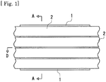
- Fig. 1 is a schematic plan view showing a positional relationship between a negative-pressure sheet structure and strips.
- a negative-pressure sheet structure 1 to which the present invention is applied is disposed at the lower side of strips 2 to be threaded through a slitter line or at the lower side of a coil not shown before slitting.
- the following embodiments can be adopted.
- Embodiments of the present invention are not limited to the following content, and the following content is shown by way of example.
- the drawings shown in Fig. 1 , Figs. 2 , and Figs. 7 to Fig. 15 show schematic structures for description, and are not intended to limit the size and scale of the structure in the present invention.
- a tabular negative-pressure sheet 3 as a first embodiment of a negative-pressure sheet structure is described.
- Figs. 2 are a sectional view taken in the A-A direction in Fig. 1 in the first embodiment ( Fig. 2(a) ), and a sectional view taken in the arrow B direction in Fig. 2 (a) (Fig. 2(b) ).
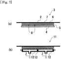
- Figs. 7 are a sectional view taken in the arrow C direction in Fig. 2(a) ( Fig. 7(a) ), and a schematic sectional view of the negative-pressure sheet structure provided with a plurality of negative-pressure common paths ( Fig. 7(b) ).
- the tabular negative-pressure sheet 3 includes a baseplate 4, a sheet 5 with conduction grooves, a nonwoven cloth lamination outer layer 6, and a surface layer member 7.
- the baseplate 4 is a member as a base of the tabular negative-pressure sheet 3, and is made of a metal.
- the sheet 5 with conduction grooves is a member disposed at the outer side of the baseplate 4, and has negative-pressure conduction grooves 8 formed on the surface.
- the negative-pressure conduction grooves 8 are formed in a direction substantially perpendicular to a direction in which strips 2 are threaded, and a negative pressure is generated as far as an end portion of the tabular negative-pressure sheet 3.
- the baseplate 4 and the sheet 5 with conduction grooves correspond to the main body.
- the nonwoven cloth lamination outer layer 6 is made of a nonwoven cloth, and is formed at the outer side of the sheet 5 with conduction grooves. Due to low air permeability of the nonwoven cloth lamination outer layer 6, an outside air inflow is miniscule in amount, and a negative pressure inside the tabular negative-pressure sheet 3 can be increased.
- the nonwoven cloth lamination outer layer 6 has air permeability of 1.0 cm 3 /cm 2 /s or less in terms of Frazier air permeability.
- a surface layer member 7 made of artificial leather with a larger frictional coefficient than the nonwoven cloth is disposed at the outer side of the nonwoven cloth lamination outer layer.
- the surface layer member 7 is a portion that comes into contact with surfaces of strips 2, and numerous throughholes are formed in the surface layer member 7. Through these throughholes, a negative pressure is generated as far as the surface. Further, the throughholes of the surface layer member 7 have a hole diameter of approximately 0.2 mm, and are formed at intervals of approximately 1 mm.
- the baseplate 4, the sheet 5 with conduction grooves, the nonwoven cloth lamination outer layer 6, and the surface layer member 7 are respectively fixed, and are structured so as not to separate even when pulled by movements of the strips 2 being threaded through the line. Further, the nonwoven cloth lamination outer layer 6 and the surface layer member 7 can be easily replaced according to degradation and contamination.
- the material forming the baseplate 4 is not particularly limited, and can be properly changed according to the purpose of use.
- a thin plate of aluminum or soft brass is used to make the baseplate bendable along the curved portion.
- the baseplate 4 and the sheet 5 with conduction grooves do not necessarily have to be used, and it is only required that a structure that generates a negative pressure inside the tabular negative-pressure sheet is provided.
- a structure in which a baseplate 4 having grooves similar to the negative-pressure conduction grooves 8 and a sheet 5 with conduction grooves are integrated in the baseplate 4 by plastic molding can also be adopted.
- the negative-pressure conduction grooves 8 do not necessarily have to be formed in a direction substantially perpendicular to a threading direction of the strips 2, and it is only required that a structure that generates a negative pressure as far as an end portion of the tabular negative-pressure sheet 3 is provided.
- the negative-pressure conduction grooves 8 are preferably formed in a direction substantially perpendicular to a threading direction of the strips 2 from the point that it becomes possible to uniformly apply a negative pressure to the strips regardless of the plate widths of the strips.
- the nonwoven cloth lamination outer layer 6 does not necessarily have to have air permeability of 1.0 cm 3 /cm 2 /s or less in terms of Frazier air permeability.
- the nonwoven cloth lamination outer layer 6 preferably has air permeability of 1.0 cm 3 /cm 2 /s in terms of Frazier air permeability from the point that a sufficient gripping force can be applied to strips to be threaded.
- the surface layer member 7 made of artificial leather with a larger frictional coefficient than the nonwoven cloth does not necessarily have to be disposed at the outer side of the nonwoven cloth lamination outer layer 6.
- a structure in which the nonwoven cloth lamination outer layer 6 comes into contact with surfaces of strips can also be adopted.
- the surface layer member 7 made of artificial leather with a larger frictional coefficient than the nonwoven cloth is preferably disposed at the outer side of the nonwoven cloth lamination outer layer 6 from the point that frictional resistance with a strip surface increases, the gripping force to be applied to the strips can be increased, and a structure suitable for imparting a preliminary tension before a tension device is obtained.
- the material forming the surface layer member 7 is not limited to artificial leather, and is only required to have a larger frictional coefficient than the nonwoven cloth lamination outer layer 6.
- the surface layer member 7 is made of a rubber material.
- the hole diameter and intervals of the throughholes of the surface layer member 7 are not particularly limited, and it is only required that a negative pressure is applied to strips.
- the baseplate 4, the sheet 5 with conduction grooves, the nonwoven cloth lamination outer layer 6, and the surface layer member 7 do not necessarily have to be respectively fixed, and are only required not to separate from each other when pulled by movements of strips 2 threaded through the line.
- a structure in which all of these components are integrally fixed by using an adhesive sheet, etc., with air permeability can also be adopted.
- negative-pressure conduction holes 9 penetrating through the sheet 5 with conduction grooves are formed.
- the negative-pressure conduction holes 9 serve as air flow passages when air inside the tabular negative-pressure sheet 3 is removed by a vacuum pump.
- a negative-pressure common path 10 is provided, and serves as a suction port for generating a negative pressure inside the tabular negative-pressure sheet 3.
- the arrow Z shows a direction in which the tabular negative-pressure sheet 3 is suctioned by a vacuum pump.
- a negative-pressure regulating valve and a negative-pressure gauge not shown are provided by being connected to the negative-pressure common path 10.
- the negative-pressure regulating valve is a valve that adjusts a volume of air flowing in the negative-pressure common path 10.
- a large-capacity exhaust blower as a suction device.
- a vacuum pump, an ejector, or the like which generates a high degree of vacuum in spite of its comparatively small suction amount can be used.
- the tabular negative-pressure sheet 3 by applying a nonwoven cloth with low air permeability, a large suction structure or a structure to adjust a suction region becomes unnecessary, so that the tabular negative-pressure sheet can be formed as a thin sheet-like structure.
- the negative-pressure common path 10 does not necessarily have to be provided, and it is only required that a structure that can make the pressure inside the tabular negative-pressure sheet 3 negative is provided.
- the negative-pressure regulating valve and the negative-pressure gauge do not necessarily have to be provided.
- the negative-pressure regulating valve and the negative-pressure gauge are preferably provided from the point that a negative pressure to be generated inside the sheet becomes adjustable and the negative-pressure suctioning efficiency can be improved.
- one negative-pressure conduction hole 9 is provided for one negative-pressure conduction groove 8.
- a plurality of negative-pressure conduction grooves 8 are formed at fixed intervals along a direction in which strips 2 are threaded, and at the lower side of these grooves, a plurality of negative-pressure conduction holes 9 are similarly formed at fixed intervals.
- the arrow Z shows a direction in which the tabular negative-pressure sheet 3 is suctioned by a vacuum pump.
- the negative-pressure conduction grooves 8 and the negative-pressure conduction holes 9 do not necessarily have to be plurally formed at fixed intervals along a direction in which the strips 2 are threaded, and it is only required that a structure that imparts a gripping force to the strips 2 by a negative pressure is provided.
- pluralities of negative-pressure conduction grooves 8 and negative-pressure conduction holes 9 are preferably formed at fixed intervals along a direction in which the strips 2 are threaded from the point that a negative pressure can be uniformly applied to the strips regardless of the slit widths.
- a nonwoven cloth used for the nonwoven cloth lamination outer layer 6 of the tabular negative-pressure sheet 3 is described.
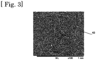
- Fig. 3 is a view showing a magnified microscopic photograph of a nonwoven cloth used for the nonwoven cloth lamination outer layer 6 of the tabular negative-pressure sheet 3.
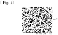
- Fig. 4 is a view showing a magnified microscopic photograph of a general nonwoven cloth.
- Fig. 5 is a view showing a magnified microscopic photograph of a high-density woven cloth.
- Fig. 6 is a view showing a magnified microscopic photograph of a general woven cloth.
- Fig. 3 shows a microscopic photograph (100 magnifications) of a nonwoven cloth 43 used for the nonwoven cloth lamination outer layer 6 of the tabular negative-pressure sheet 3.
- the nonwoven cloth 43 is formed by entwining fibers with a diameter of approximately 4 ⁇ m at high density.
- a single nonwoven cloth 43 can realize low air permeability of approximately 0.8 cm 3 /cm 2 /s in terms of Frazier air permeability. Further, it is characterized that among respective extra fine fibers of this nonwoven cloth 43, numerous micrometer-sized gaps exist, and through the gaps, a negative pressure can easily reach the entire surface of the nonwoven cloth lamination outer layer 6.
- Fig. 4 shows a microscopic photograph of a nonwoven cloth 44 generally used for tension pads that are one of the tension devices.
- the nonwoven cloth 44 is formed by entwining fibers with a fiber diameter of approximately 20 to 30 ⁇ m, and is lower in density than the nonwoven cloth 43. Further, a single nonwoven cloth 44 has Frazier air permeability of 50 to 100 cm 3 /cm 2 /s, and is difficult to use as a nonwoven cloth of the nonwoven cloth lamination outer layer 6.
- nonwoven cloth 44 by combining the nonwoven cloth 44 with a high-density woven cloth 45 made of a material with low air permeability of approximately 0.8 cm 3 /cm 2 /s in terms of Frazier air permeability, for example, nylon woven cloth or the like, low air permeability can also be realized. That is, it is also possible that by sandwiching the high-density woven cloth 45 between nonwoven cloths 44, the nonwoven cloth lamination outer layer 6 is formed. Magnified microscopic photographs (100 magnifications) of the high-density woven cloth 45 and a general woven cloth 46 are respectively shown in Fig. 5 and Fig. 6 .
- the nonwoven cloth lamination outer layer 6 does not necessarily have to be formed of one nonwoven cloth 43.
- a structure that lowers air permeability by laminating a plurality of nonwoven cloths can also be adopted.
- a section in a region of the tabular negative-pressure sheet 3 in which the negative-pressure conduction holes 9 and the negative-pressure common path 10 are absent has the structure shown in Fig. 7(a) .
- the tabular negative-pressure sheet 3 described above is structured so that a single negative-pressure common path 10 is provided for the plurality of negative-pressure conduction holes 9, however, in the present invention, a negative-pressure common path structure shown in Fig. 7(b) can also be adopted.
- a tabular negative-pressure sheet 11 shown in Fig. 7 (b) two negative-pressure common paths 12 are provided, and between these, a partition 13 is formed.
- a negative-pressure regulating valve is provided in each negative-pressure common path 12, to form a structure that can adjust a negative pressure.
- the arrow Z shows a direction in which the tabular negative-pressure sheet 11 is suctioned by a vacuum pump.
- a gripping force to be applied to the strip 2 can be changed according to the thickness of the strip 2 to be threaded.
- a tabular negative-pressure sheet 14 that is a second embodiment of the negative-pressure sheet structure is described.
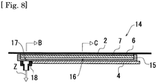
- Fig. 8 is a sectional view taken in the arrow D direction in Fig. 1 in the second embodiment.
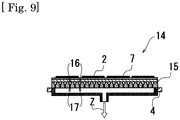
- Fig. 9 is a sectional view taken in the arrow B direction in Fig. 8 .
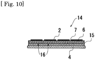
- Fig. 10 is a sectional view taken in the arrow C direction in Fig. 8 .
- Fig. 11 is a schematic sectional view of a negative-pressure sheet structure provided with a plurality of negative-pressure common paths.
- the tabular negative-pressure sheet 14 includes a baseplate 4, a sheet 15 with conduction grooves, a nonwoven cloth lamination outer layer 6, and a surface layer member 7.
- negative-pressure conduction grooves 16 are formed on the surface of the sheet 15 with conduction grooves.
- negative-pressure conduction grooves 16 are formed in a direction substantially parallel to a direction in which strips 2 are threaded so that a negative pressure is generated as far as an end portion of the tabular negative-pressure sheet 14.
- negative-pressure conduction holes 17 penetrating through the sheet 15 with conduction grooves are formed. Further, between the negative-pressure conduction holes 17 and a vacuum pump, a negative-pressure common path 18 is provided.
- the arrow Z shows a direction in which the tabular negative-pressure sheet 14 is suctioned by the vacuum pump.
- one negative-pressure conduction hole 17 is provided for one negative-pressure conduction groove 16.
- a plurality of negative-pressure conduction grooves 16 are formed at fixed intervals, and at the lower side of these grooves, negative-pressure conduction holes 17 are similarly formed at fixed intervals.
- the tabular negative-pressure sheet 14 and the tabular negative-pressure sheet 3 described above are different in negative-pressure conduction groove forming directions from each other.
- the arrow Z shows a direction in which the tabular negative-pressure sheet 14 is suctioned by a vacuum pump.
- a section in a region of the tabular negative-pressure sheet 14 in which the negative-pressure conduction holes 17 and the negative-pressure common path 18 are absent has the structure shown in Fig. 10 .
- a structure provided with a plurality of negative-pressure common paths can also be adopted.
- a tabular negative-pressure sheet 19 shown in Fig. 11 two negative-pressure common paths 20 are provided, and between these, a partition 21 is formed.
- the arrow Z shows a direction in which the tabular negative-pressure sheet 19 is suctioned by a vacuum pump.
- a gripping force to be applied to the strip 2 can be changed according to the thickness of the strip 2 to be threaded.
- a negative-pressure regulating valve 22 is provided in each of the two negative-pressure common paths 20 of the tabular negative-pressure sheet 19, so that a negative pressure is adjustable.
- strips 2 are present on the surface layer member 7 in a region 23, and no strips 2 are threaded in a region 24.
- the arrow Z shows a direction in which the tabular negative-pressure sheet 19 is suctioned by a vacuum pump.
- a tabular negative-pressure sheet 25 that is a third embodiment of the negative-pressure sheet structure is described.
- Figs. 13 are a schematic sectional view of a negative-pressure sheet provided with a porous plate as an intermediate layer portion ( Fig. 13 (a) ), a sectional view taken in the arrow B direction in Fig. 13(a) (Fig. 13(b) ), and a sectional view taken in the arrow C direction in Fig. 13(a) (Fig. 13(c) ).
- the tabular negative-pressure sheet 25 includes a baseplate 4, a sheet 26 with conduction grooves, an intermediate layer 27, a nonwoven cloth lamination outer layer 6, and a surface layer member 7.
- negative-pressure conduction grooves 28 with a groove width of more than 3 mm are formed on the surface of the sheet 26 with conduction grooves. Further, in the tabular negative-pressure sheet 25, negative-pressure conduction grooves 28 are formed in a direction substantially perpendicular to a direction in which strips 2 are threaded so that a negative pressure is generated as far as an end portion of the tabular negative-pressure sheet 26.
- negative-pressure conduction holes 29 penetrating through the sheet 26 with conduction grooves are formed on one end side of the sheet 26 with conduction grooves. Further, between the negative-pressure conduction holes 29 and a vacuum pump, a negative-pressure common path 30 is provided.
- the arrow Z shows a direction in which the tabular negative-pressure sheet 25 is suctioned by the vacuum pump.
- the intermediate layer 27 is formed of a punching metal in which numerous vent holes 31 are formed, and through the vent holes 31, a negative pressure generated in the negative-pressure conduction holes 29 and the negative-pressure conduction grooves 28 reaches the nonwoven cloth lamination layer 6.
- Fig. 13(b) shows a region in which the negative-pressure conduction holes 29 and the negative-pressure common path 30 are present
- Fig. 13 (c) shows a region in which the negative-pressure conduction holes 29 and the negative-pressure common path 30 are absent.
- the arrow Z shows a direction in which the tabular negative-pressure sheet 25 is suctioned by the vacuum pump.
- the intermediate layer 27 makes it difficult for the nonwoven cloth lamination outer layer 6 to fall in the negative-pressure conduction grooves 28, so that a structure that makes it difficult for unevenness to occur on the surface of the nonwoven cloth lamination outer layer 6 is obtained.
- the first embodiment, the second embodiment, and the third embodiment of the present invention described above are negative-pressure sheet structures formed to be tabular which can be disposed in a region of a slitter line in which strips are threaded in the horizontal direction.
- the tabular negative-pressure sheet structure can be disposed before a tension device of a slitter line.
- a gripping force generated by a negative pressure to one-side surfaces of the strips, a preliminary tension for preventing the strips from meandering can be applied.
- the negative-pressure sheet structure is structured so that air permeability inside the negative-pressure sheet structure is kept low, even if air is suctioned through gaps between multiple strips after slitting, the negative pressure can be maintained and the gripping force can be kept. This advantage can be obtained even when the slit widths of the strips are different, so that the structure can adapt to strips with various slit widths.
- a pressure to be applied to strip surfaces is softer than in a meandering preventive structure of tension pads that sandwich and press strips from upper and lower sides by felts, and it is difficult to make scratches and contamination on the strip surfaces, and further, a sufficient preliminary tension can be imparted to the strips by the negative pressure.
- no damage is caused by this structure on a surface of a strip on the side that does not come into contact with the negative-pressure sheet structure, so that a strip having no damage on one surface can be obtained. As a result, a product coil having a neat winding form can be produced.
- the contact area with strips increases, and this makes it more difficult to make scratches on the surfaces.
- one-side surface of the surfaces of a strip does not come into contact with other structural bodies, so that a preliminary tension can be imparted thereto without making scratches and contamination.
- the tabular negative-pressure sheet structure can be used as a tension device to impart a winding tension by being disposed before a winding coil of a slitter line.
- a metal strip formed of a very thin plate with a thickness of less than 0.1 mm like a metal foil may be used as a target to which a tension is imparted.
- the negative-pressure sheet structure can impart a winding tension to strips by a gripping force generated by a negative pressure and a frictional force of the surface layer member.
- the tabular negative-pressure sheet structure can be disposed on both of the entrance side and sending-out side of a slitter of a slitter line. That is, as shown in Fig. 14 , by disposing the negative-pressure sheet structure 33 extending to the vicinity of round blades 32 of the slitter along a threading line of a coil 35 and a strip 2 before slitting, a gripping force generated by a negative pressure can be applied to the coil 35 and the strip 2, and accordingly, stable threading is enabled.
- a portion that comes into contact with a strip 2 is a surface layer member 34 made of fluorine resin. Further, in the surface layer member 34, numerous fine throughholes are formed.
- the fluorine resin forming the surface layer member 34 is a material with a small frictional coefficient, and frictional resistance applied from the negative-pressure sheet structure 33 to the surface of the strip 2 is smaller than frictional resistance applied from the tabular negative-pressure sheet 3 using artificial leather for the surface layer member 7 to the surface of the strip 2.
- a force smaller than a gripping force when imparting a preliminary tension to the strip 2 before a tension device can be sufficient. Further, an excessively strong gripping force disturbs smooth threading of the coil 35 and the strip 2.
- the gripping force is reduced, and a gripping force proper for plate pressing of the slitter is realized.
- the gripping force can also be adjusted by using the negative-pressure regulating valve described above.
- the surface layer member 34 does not necessarily have to be provided in the negative-pressure sheet structure 33, and depending on a material and plate thickness of a target strip, a nonwoven cloth lamination outer layer formed of a nonwoven cloth may be used as a member that comes into contact with a coil and a strip.
- the surface layer member 34 is preferably provided in the negative-pressure sheet structure 33 from the point that the frictional resistance can be further reduced and both of smooth threading and plate pressing of a strip can be realized as described above.
- the negative-pressure sheet structure 33 grips the coil 35 with a wide width before slitting by a negative pressure and suppresses up-down movements of the coil 35, so that the coil 35 can be supplied in a flat state to the round blades 32 of the slitter. Further, at the sending-out side of the slitter, the negative-pressure sheet structure grips the strip 2 by a negative pressure and can suppress irregular up-down movements of the strip 2 caused by the round blades 32 of the slitter.
- the negative-pressure sheet structure 33 is structured so as to impart a gripping force to a strip regardless of a slit width of the strip, so that there is no need to prepare a member suited to the slit width of the strip. That is, component replacement for each slit width of strips is unnecessary, so that the structure is very conveniently used.
- the negative-pressure sheet structure 33 to be disposed on both of the entrance side and the sending-out side of the slitter, like the tabular negative-pressure sheet 14 and the tabular negative-pressure sheet 19 described above, a structure in which negative-pressure conduction grooves are formed in a direction substantially parallel to a direction in which the coil 35 and the strip 2 are threaded is preferably adopted although this is not essential.
- pressing means a phenomenon in which the atmospheric pressure acts from the surface side due to a negative pressure on the strip back surface.
- the negative-pressure sheet structure to which the present invention is applied can also be adopted for a structure to be disposed at a curved portion at a rise of a loop pit, and for example, the following fourth embodiment is possible.
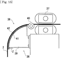
- a curved negative-pressure sheet 36 shown in Fig. 15 is described.
- Fig. 15 is a schematic view showing a structure and disposed position of a curved negative-pressure sheet structure.
- the curved negative-pressure sheet 36 is structured similar to the tabular negative-pressure sheet 3 described above except for the following different points.
- the curved negative-pressure sheet 36 is disposed at a curved portion 38 at a rise of a loop pit before a belt-type tension device 37 of a slitter line. Further, the curved negative-pressure sheet 36 includes a baseplate 39 having a curved surface. The baseplate 39 can be disposed adjacent to a separator 40 disposed at the curved portion 38.
- a sheet 41 with conduction grooves made of bendable soft plastic is disposed at the outer side of the baseplate 39.
- negative-pressure conduction grooves 42 are formed on the surface of the sheet 41 with conduction grooves.
- the structure other than these is in common with the structure of the tabular negative-pressure sheet 3, and by contacting with a surface of a strip 2 passing through the curved portion 38, a gripping force is generated.
- Fig. 15 is a schematic view of the curved negative-pressure sheet 36, and members common to the tabular negative-pressure sheet 3 are not shown. Further, the arrow Z shows a direction in which the curved negative-pressure sheet 36 is suctioned by a vacuum pump.
- the curved negative-pressure sheet 36 is a structure positioned along the curved portion 38 at the rise of the loop pit, and applies a gripping force generated by a negative pressure to the strip 2, suppresses jumping up and meandering of the strip at the curved portion, and provides the strip 2 with rectilinearity.
- the long portion of the curved portion 38 guides threading of the strip 2, so that threading of the strip 2 can be sufficiently stabilized.
- the threading speed of the strip 2 on the line can be made high, and accordingly, the productivity can be improved.
- a structure is preferably adopted in which negative-pressure conduction grooves are formed in a direction substantially parallel to a direction in which the strip 2 is threaded although this is not essential.
- a plurality of negative-pressure conduction holes leading to the negative-pressure conduction grooves are formed in a direction substantially perpendicular to the direction in which the strip 2 is threaded. That is, as compared with a case where negative-pressure conduction holes are formed along a curved surface, they can be formed more easily, and this brings about an advantage in manufacturing.
- this structure can also be disposed at the curved portion of the loop pit provided before the slitter as well as at the loop pit before the tension device. In this case, by applying a gripping force to a coil before slitting, meandering of the coil can be suppressed.
- the baseplate 39 does not necessarily have to have the curved surface, and is only required to be capable of being disposed along the curved portion at the rise of the loop pit.
- a structure enabling fitting to the curve of the curved portion by adopting a bendable plate made of aluminum or a thin plate made of soft brass with a thickness of 3 mm to 5 mm is also possible.
- the material of the sheet 41 with conduction grooves is not limited, and the sheet is only required to be capable of being disposed along the curved portion at the rise of the loop pit.
- the sheet can be made of synthetic rubber.
- the negative-pressure sheet structure according to the present invention makes it difficult to cause harmful damage on strip surfaces, and enables stable strip threading in a metal strip slitter line.
Landscapes
- Engineering & Computer Science (AREA)
- Mechanical Engineering (AREA)
- Textile Engineering (AREA)
- Physics & Mathematics (AREA)
- Fluid Mechanics (AREA)
- Winding, Rewinding, Material Storage Devices (AREA)
- Treatment Of Fiber Materials (AREA)
- Shearing Machines (AREA)
- Accessories And Tools For Shearing Machines (AREA)
Applications Claiming Priority (1)
| Application Number | Priority Date | Filing Date | Title |
|---|---|---|---|
| PCT/JP2014/055997 WO2015132961A1 (ja) | 2014-03-07 | 2014-03-07 | 負圧シート構造 |
Publications (3)
| Publication Number | Publication Date |
|---|---|
| EP3115138A1 true EP3115138A1 (de) | 2017-01-11 |
| EP3115138A4 EP3115138A4 (de) | 2017-10-25 |
| EP3115138B1 EP3115138B1 (de) | 2021-01-27 |
Family
ID=54054793
Family Applications (1)
| Application Number | Title | Priority Date | Filing Date |
|---|---|---|---|
| EP14884506.8A Active EP3115138B1 (de) | 2014-03-07 | 2014-03-07 | Unterdruckfolienstruktur |
Country Status (6)
| Country | Link |
|---|---|
| US (1) | US20170216897A1 (de) |
| EP (1) | EP3115138B1 (de) |
| JP (1) | JP6066014B2 (de) |
| KR (1) | KR101894445B1 (de) |
| CN (1) | CN106170359B (de) |
| WO (1) | WO2015132961A1 (de) |
Families Citing this family (5)
| Publication number | Priority date | Publication date | Assignee | Title |
|---|---|---|---|---|
| US11884377B2 (en) * | 2018-12-21 | 2024-01-30 | The Boeing Company | High-density robotic system |
| US11584503B2 (en) * | 2018-12-21 | 2023-02-21 | The Boeing Company | High-density robotic system |
| CN112339276B (zh) * | 2019-08-06 | 2022-11-15 | 中国科学院宁波材料技术与工程研究所 | 一种纤维增强热塑性预浸片材叠层成型生产线装置及工艺 |
| JP7256773B2 (ja) * | 2020-04-24 | 2023-04-12 | 信越化学工業株式会社 | 平坦性制御方法、塗膜の形成方法、平坦性制御装置、及び塗膜形成装置 |
| CN120503409B (zh) * | 2025-07-18 | 2025-09-12 | 四川博科斯电力科技有限公司 | 一种复合材料杆生产线用铺纱组件 |
Family Cites Families (28)
| Publication number | Priority date | Publication date | Assignee | Title |
|---|---|---|---|---|
| JPH0543925Y2 (de) * | 1986-12-24 | 1993-11-08 | ||
| JPH05318221A (ja) | 1991-02-15 | 1993-12-03 | Sumikura Ind Co Ltd | カテナリーガイド上の板押え装置 |
| JP3033627B2 (ja) * | 1991-12-17 | 2000-04-17 | 古河電気工業株式会社 | 金属条のスリッティング装置 |
| JPH0722775B2 (ja) | 1992-12-08 | 1995-03-15 | 山王鉄工株式会社 | 金属帯板の張力付与装置 |
| JPH07127631A (ja) | 1993-11-05 | 1995-05-16 | Berumateitsuku:Kk | 吸気幅可変型サクションローラ |
| JPH1158124A (ja) | 1997-06-13 | 1999-03-02 | Nkk Corp | 高珪素鋼帯のスリット設備 |
| JP2000021008A (ja) | 1998-07-03 | 2000-01-21 | Ricoh Co Ltd | 光ピックアップ装置 |
| JP2000312989A (ja) * | 1999-04-28 | 2000-11-14 | Toyota Motor Corp | 薄板のクランプ方法 |
| JP2001137955A (ja) * | 1999-11-08 | 2001-05-22 | Mitsubishi Heavy Ind Ltd | メンブレンの製造装置及びその製造方法 |
| JP2003191121A (ja) * | 2001-12-21 | 2003-07-08 | Nisshin Steel Co Ltd | 金属帯案内用フィンガー構造 |
| JP2003312909A (ja) * | 2002-04-22 | 2003-11-06 | Hikoyama Seiki Kk | 自己吸引式サクションロール及びこのサクションロールを用いたフィルム状基材の搬送装置 |
| JP3950040B2 (ja) * | 2002-08-30 | 2007-07-25 | 東芝機械株式会社 | サクションロール装置 |
| JP2005093938A (ja) * | 2003-09-19 | 2005-04-07 | Shin Etsu Polymer Co Ltd | 基板保持具 |
| DE102004031997A1 (de) * | 2004-07-01 | 2006-01-26 | Infineon Technologies Ag | Gehäuse für ein Halbleiter-Bauelement und Halbleiter-Bauelement-Test-System zum Testen der Kontaktierung bei übereinander angeordneten Halbleiter-Bauelementen |
| US7044416B2 (en) * | 2004-07-28 | 2006-05-16 | Gonzalo Salvador | Tensioning board for slit metal rewinding |
| CN101229598B (zh) * | 2008-01-23 | 2010-06-02 | 北京航空航天大学 | 组合式蒙皮型面切边柔性多点支撑装置 |
| TWI439351B (zh) * | 2008-09-29 | 2014-06-01 | 日東電工股份有限公司 | Adsorption tablets |
| JP4625516B2 (ja) * | 2008-10-06 | 2011-02-02 | 株式会社日本開発コンサルタント | ベルト式帯板巻取り張力付与装置のスリット入りエンドレスベルト |
| JP5201511B2 (ja) * | 2009-01-19 | 2013-06-05 | 株式会社タカトリ | ウエハの保持テーブル |
| JP2010173842A (ja) | 2009-02-02 | 2010-08-12 | Daiei Seisakusho:Kk | サクションロール |
| DE102009028215B3 (de) * | 2009-08-04 | 2010-09-09 | Voith Patent Gmbh | Kombination eines Pressfilzes mit einem Presswalzenbezug und/oder einem Saugwalzenbezug für eine Papiermaschine |
| US8552790B2 (en) * | 2010-07-21 | 2013-10-08 | Mediatek Singapore Pte. Ltd. | Harmonic rejection of signal converting device and method thereof |
| JP5201642B2 (ja) * | 2011-07-19 | 2013-06-05 | 株式会社日本製鋼所 | 吸着装置および処理装置 |
| JP5050131B1 (ja) | 2012-02-18 | 2012-10-17 | 和信産業株式会社 | スリッタスタンド及びスリッタライン |
| CN102909285B (zh) * | 2012-11-17 | 2015-02-25 | 柳州六和方盛机械有限公司 | 钢板剪料自动送料机构 |
| CN202894114U (zh) * | 2012-11-17 | 2013-04-24 | 柳州六和方盛机械有限公司 | 钢板剪料自动送料机构 |
| JP5565889B1 (ja) * | 2013-02-06 | 2014-08-06 | Jdc株式会社 | サクションロール装置 |
| JP5652800B1 (ja) * | 2014-02-03 | 2015-01-14 | Jdc株式会社 | スリッターラインのループ量吸収装置 |
-
2014
- 2014-03-07 WO PCT/JP2014/055997 patent/WO2015132961A1/ja not_active Ceased
- 2014-03-07 KR KR1020167023409A patent/KR101894445B1/ko active Active
- 2014-03-07 US US15/123,990 patent/US20170216897A1/en not_active Abandoned
- 2014-03-07 CN CN201480076857.XA patent/CN106170359B/zh active Active
- 2014-03-07 JP JP2016506058A patent/JP6066014B2/ja active Active
- 2014-03-07 EP EP14884506.8A patent/EP3115138B1/de active Active
Also Published As
| Publication number | Publication date |
|---|---|
| EP3115138A4 (de) | 2017-10-25 |
| CN106170359B (zh) | 2018-10-02 |
| JPWO2015132961A1 (ja) | 2017-03-30 |
| KR20160114128A (ko) | 2016-10-04 |
| JP6066014B2 (ja) | 2017-01-25 |
| WO2015132961A1 (ja) | 2015-09-11 |
| CN106170359A (zh) | 2016-11-30 |
| US20170216897A1 (en) | 2017-08-03 |
| KR101894445B1 (ko) | 2018-09-03 |
| EP3115138B1 (de) | 2021-01-27 |
Similar Documents
| Publication | Publication Date | Title |
|---|---|---|
| CN105008259B (zh) | 吸辊装置 | |
| EP3115138B1 (de) | Unterdruckfolienstruktur | |
| JP6338642B2 (ja) | ハンドリングタブを連続的なガラスリボンに貼り付ける方法および装置 | |
| JP4808417B2 (ja) | 積層研磨パッドを形成する方法 | |
| US8162250B2 (en) | Endless belt with slits for belt-type band sheet coiling tension applying apparatus | |
| EP3103556B1 (de) | Bandspeicher für längsschneidelinien | |
| CN103058002B (zh) | 一种双层薄膜叠加分切装置及方法 | |
| JP2018140857A (ja) | ウェブ加工装置 | |
| CN203095253U (zh) | 一种双层薄膜叠加分切装置 | |
| JP2014101159A (ja) | 搬送装置 | |
| JP2008081287A (ja) | 粘着性極細幅長尺テープ捲回物の製造方法及び同装置 | |
| JP5063193B2 (ja) | ラベル連続体の生産装置 | |
| WO2009118826A1 (ja) | 粘着性極細幅長尺テープ捲回物の製造方法及び同装置 | |
| JP2014231431A (ja) | 分離取出装置、及び分離取出方法 | |
| JP5787241B1 (ja) | 帯状シート接続用吸着台及び帯状シート接続方法 | |
| HK1215941B (en) | Suction roll device | |
| JP6976074B2 (ja) | 搬送装置および積層体の製造方法 | |
| JP2021088442A (ja) | 基材搬送装置及び基材処理装置 | |
| JP2009274861A (ja) | フィルム体搬送装置およびフィルム体加工システム |
Legal Events
| Date | Code | Title | Description |
|---|---|---|---|
| PUAI | Public reference made under article 153(3) epc to a published international application that has entered the european phase |
Free format text: ORIGINAL CODE: 0009012 |
|
| STAA | Information on the status of an ep patent application or granted ep patent |
Free format text: STATUS: REQUEST FOR EXAMINATION WAS MADE |
|
| 17P | Request for examination filed |
Effective date: 20160830 |
|
| AK | Designated contracting states |
Kind code of ref document: A1 Designated state(s): AL AT BE BG CH CY CZ DE DK EE ES FI FR GB GR HR HU IE IS IT LI LT LU LV MC MK MT NL NO PL PT RO RS SE SI SK SM TR |
|
| AX | Request for extension of the european patent |
Extension state: BA ME |
|
| DAX | Request for extension of the european patent (deleted) | ||
| A4 | Supplementary search report drawn up and despatched |
Effective date: 20170927 |
|
| RIC1 | Information provided on ipc code assigned before grant |
Ipc: B21C 47/34 20060101ALI20170921BHEP Ipc: B21C 47/26 20060101ALI20170921BHEP Ipc: B32B 3/24 20060101ALI20170921BHEP Ipc: B21C 47/00 20060101ALI20170921BHEP Ipc: B23D 33/02 20060101AFI20170921BHEP Ipc: B23Q 3/08 20060101ALI20170921BHEP |
|
| STAA | Information on the status of an ep patent application or granted ep patent |
Free format text: STATUS: EXAMINATION IS IN PROGRESS |
|
| 17Q | First examination report despatched |
Effective date: 20190405 |
|
| GRAP | Despatch of communication of intention to grant a patent |
Free format text: ORIGINAL CODE: EPIDOSNIGR1 |
|
| STAA | Information on the status of an ep patent application or granted ep patent |
Free format text: STATUS: GRANT OF PATENT IS INTENDED |
|
| INTG | Intention to grant announced |
Effective date: 20200916 |
|
| GRAS | Grant fee paid |
Free format text: ORIGINAL CODE: EPIDOSNIGR3 |
|
| GRAA | (expected) grant |
Free format text: ORIGINAL CODE: 0009210 |
|
| STAA | Information on the status of an ep patent application or granted ep patent |
Free format text: STATUS: THE PATENT HAS BEEN GRANTED |
|
| AK | Designated contracting states |
Kind code of ref document: B1 Designated state(s): AL AT BE BG CH CY CZ DE DK EE ES FI FR GB GR HR HU IE IS IT LI LT LU LV MC MK MT NL NO PL PT RO RS SE SI SK SM TR |
|
| REG | Reference to a national code |
Ref country code: GB Ref legal event code: FG4D |
|
| REG | Reference to a national code |
Ref country code: CH Ref legal event code: EP |
|
| REG | Reference to a national code |
Ref country code: AT Ref legal event code: REF Ref document number: 1357888 Country of ref document: AT Kind code of ref document: T Effective date: 20210215 Ref country code: CH Ref legal event code: NV Representative=s name: HEPP WENGER RYFFEL AG, CH |
|
| REG | Reference to a national code |
Ref country code: IE Ref legal event code: FG4D |
|
| REG | Reference to a national code |
Ref country code: DE Ref legal event code: R096 Ref document number: 602014074662 Country of ref document: DE |
|
| REG | Reference to a national code |
Ref country code: NL Ref legal event code: MP Effective date: 20210127 |
|
| REG | Reference to a national code |
Ref country code: LT Ref legal event code: MG9D |
|
| REG | Reference to a national code |
Ref country code: AT Ref legal event code: MK05 Ref document number: 1357888 Country of ref document: AT Kind code of ref document: T Effective date: 20210127 |
|
| PG25 | Lapsed in a contracting state [announced via postgrant information from national office to epo] |
Ref country code: FI Free format text: LAPSE BECAUSE OF FAILURE TO SUBMIT A TRANSLATION OF THE DESCRIPTION OR TO PAY THE FEE WITHIN THE PRESCRIBED TIME-LIMIT Effective date: 20210127 Ref country code: HR Free format text: LAPSE BECAUSE OF FAILURE TO SUBMIT A TRANSLATION OF THE DESCRIPTION OR TO PAY THE FEE WITHIN THE PRESCRIBED TIME-LIMIT Effective date: 20210127 Ref country code: GR Free format text: LAPSE BECAUSE OF FAILURE TO SUBMIT A TRANSLATION OF THE DESCRIPTION OR TO PAY THE FEE WITHIN THE PRESCRIBED TIME-LIMIT Effective date: 20210428 Ref country code: PT Free format text: LAPSE BECAUSE OF FAILURE TO SUBMIT A TRANSLATION OF THE DESCRIPTION OR TO PAY THE FEE WITHIN THE PRESCRIBED TIME-LIMIT Effective date: 20210527 Ref country code: LT Free format text: LAPSE BECAUSE OF FAILURE TO SUBMIT A TRANSLATION OF THE DESCRIPTION OR TO PAY THE FEE WITHIN THE PRESCRIBED TIME-LIMIT Effective date: 20210127 Ref country code: BG Free format text: LAPSE BECAUSE OF FAILURE TO SUBMIT A TRANSLATION OF THE DESCRIPTION OR TO PAY THE FEE WITHIN THE PRESCRIBED TIME-LIMIT Effective date: 20210427 Ref country code: NL Free format text: LAPSE BECAUSE OF FAILURE TO SUBMIT A TRANSLATION OF THE DESCRIPTION OR TO PAY THE FEE WITHIN THE PRESCRIBED TIME-LIMIT Effective date: 20210127 Ref country code: NO Free format text: LAPSE BECAUSE OF FAILURE TO SUBMIT A TRANSLATION OF THE DESCRIPTION OR TO PAY THE FEE WITHIN THE PRESCRIBED TIME-LIMIT Effective date: 20210427 |
|
| PG25 | Lapsed in a contracting state [announced via postgrant information from national office to epo] |
Ref country code: SE Free format text: LAPSE BECAUSE OF FAILURE TO SUBMIT A TRANSLATION OF THE DESCRIPTION OR TO PAY THE FEE WITHIN THE PRESCRIBED TIME-LIMIT Effective date: 20210127 Ref country code: RS Free format text: LAPSE BECAUSE OF FAILURE TO SUBMIT A TRANSLATION OF THE DESCRIPTION OR TO PAY THE FEE WITHIN THE PRESCRIBED TIME-LIMIT Effective date: 20210127 Ref country code: LV Free format text: LAPSE BECAUSE OF FAILURE TO SUBMIT A TRANSLATION OF THE DESCRIPTION OR TO PAY THE FEE WITHIN THE PRESCRIBED TIME-LIMIT Effective date: 20210127 Ref country code: PL Free format text: LAPSE BECAUSE OF FAILURE TO SUBMIT A TRANSLATION OF THE DESCRIPTION OR TO PAY THE FEE WITHIN THE PRESCRIBED TIME-LIMIT Effective date: 20210127 Ref country code: AT Free format text: LAPSE BECAUSE OF FAILURE TO SUBMIT A TRANSLATION OF THE DESCRIPTION OR TO PAY THE FEE WITHIN THE PRESCRIBED TIME-LIMIT Effective date: 20210127 |
|
| PG25 | Lapsed in a contracting state [announced via postgrant information from national office to epo] |
Ref country code: IS Free format text: LAPSE BECAUSE OF FAILURE TO SUBMIT A TRANSLATION OF THE DESCRIPTION OR TO PAY THE FEE WITHIN THE PRESCRIBED TIME-LIMIT Effective date: 20210527 |
|
| REG | Reference to a national code |
Ref country code: DE Ref legal event code: R097 Ref document number: 602014074662 Country of ref document: DE |
|
| PG25 | Lapsed in a contracting state [announced via postgrant information from national office to epo] |
Ref country code: SM Free format text: LAPSE BECAUSE OF FAILURE TO SUBMIT A TRANSLATION OF THE DESCRIPTION OR TO PAY THE FEE WITHIN THE PRESCRIBED TIME-LIMIT Effective date: 20210127 Ref country code: EE Free format text: LAPSE BECAUSE OF FAILURE TO SUBMIT A TRANSLATION OF THE DESCRIPTION OR TO PAY THE FEE WITHIN THE PRESCRIBED TIME-LIMIT Effective date: 20210127 Ref country code: CZ Free format text: LAPSE BECAUSE OF FAILURE TO SUBMIT A TRANSLATION OF THE DESCRIPTION OR TO PAY THE FEE WITHIN THE PRESCRIBED TIME-LIMIT Effective date: 20210127 Ref country code: MC Free format text: LAPSE BECAUSE OF FAILURE TO SUBMIT A TRANSLATION OF THE DESCRIPTION OR TO PAY THE FEE WITHIN THE PRESCRIBED TIME-LIMIT Effective date: 20210127 |
|
| PG25 | Lapsed in a contracting state [announced via postgrant information from national office to epo] |
Ref country code: DK Free format text: LAPSE BECAUSE OF FAILURE TO SUBMIT A TRANSLATION OF THE DESCRIPTION OR TO PAY THE FEE WITHIN THE PRESCRIBED TIME-LIMIT Effective date: 20210127 Ref country code: ES Free format text: LAPSE BECAUSE OF FAILURE TO SUBMIT A TRANSLATION OF THE DESCRIPTION OR TO PAY THE FEE WITHIN THE PRESCRIBED TIME-LIMIT Effective date: 20210127 Ref country code: SK Free format text: LAPSE BECAUSE OF FAILURE TO SUBMIT A TRANSLATION OF THE DESCRIPTION OR TO PAY THE FEE WITHIN THE PRESCRIBED TIME-LIMIT Effective date: 20210127 Ref country code: RO Free format text: LAPSE BECAUSE OF FAILURE TO SUBMIT A TRANSLATION OF THE DESCRIPTION OR TO PAY THE FEE WITHIN THE PRESCRIBED TIME-LIMIT Effective date: 20210127 |
|
| PLBE | No opposition filed within time limit |
Free format text: ORIGINAL CODE: 0009261 |
|
| STAA | Information on the status of an ep patent application or granted ep patent |
Free format text: STATUS: NO OPPOSITION FILED WITHIN TIME LIMIT |
|
| REG | Reference to a national code |
Ref country code: BE Ref legal event code: MM Effective date: 20210331 |
|
| 26N | No opposition filed |
Effective date: 20211028 |
|
| PG25 | Lapsed in a contracting state [announced via postgrant information from national office to epo] |
Ref country code: LU Free format text: LAPSE BECAUSE OF NON-PAYMENT OF DUE FEES Effective date: 20210307 Ref country code: AL Free format text: LAPSE BECAUSE OF FAILURE TO SUBMIT A TRANSLATION OF THE DESCRIPTION OR TO PAY THE FEE WITHIN THE PRESCRIBED TIME-LIMIT Effective date: 20210127 Ref country code: IE Free format text: LAPSE BECAUSE OF NON-PAYMENT OF DUE FEES Effective date: 20210307 |
|
| PG25 | Lapsed in a contracting state [announced via postgrant information from national office to epo] |
Ref country code: SI Free format text: LAPSE BECAUSE OF FAILURE TO SUBMIT A TRANSLATION OF THE DESCRIPTION OR TO PAY THE FEE WITHIN THE PRESCRIBED TIME-LIMIT Effective date: 20210127 |
|
| PG25 | Lapsed in a contracting state [announced via postgrant information from national office to epo] |
Ref country code: IS Free format text: LAPSE BECAUSE OF FAILURE TO SUBMIT A TRANSLATION OF THE DESCRIPTION OR TO PAY THE FEE WITHIN THE PRESCRIBED TIME-LIMIT Effective date: 20210527 |
|
| PG25 | Lapsed in a contracting state [announced via postgrant information from national office to epo] |
Ref country code: BE Free format text: LAPSE BECAUSE OF NON-PAYMENT OF DUE FEES Effective date: 20210331 |
|
| PG25 | Lapsed in a contracting state [announced via postgrant information from national office to epo] |
Ref country code: HU Free format text: LAPSE BECAUSE OF FAILURE TO SUBMIT A TRANSLATION OF THE DESCRIPTION OR TO PAY THE FEE WITHIN THE PRESCRIBED TIME-LIMIT; INVALID AB INITIO Effective date: 20140307 |
|
| PG25 | Lapsed in a contracting state [announced via postgrant information from national office to epo] |
Ref country code: CY Free format text: LAPSE BECAUSE OF FAILURE TO SUBMIT A TRANSLATION OF THE DESCRIPTION OR TO PAY THE FEE WITHIN THE PRESCRIBED TIME-LIMIT Effective date: 20210127 |
|
| PG25 | Lapsed in a contracting state [announced via postgrant information from national office to epo] |
Ref country code: MK Free format text: LAPSE BECAUSE OF FAILURE TO SUBMIT A TRANSLATION OF THE DESCRIPTION OR TO PAY THE FEE WITHIN THE PRESCRIBED TIME-LIMIT Effective date: 20210127 |
|
| PG25 | Lapsed in a contracting state [announced via postgrant information from national office to epo] |
Ref country code: TR Free format text: LAPSE BECAUSE OF FAILURE TO SUBMIT A TRANSLATION OF THE DESCRIPTION OR TO PAY THE FEE WITHIN THE PRESCRIBED TIME-LIMIT Effective date: 20210127 |
|
| PG25 | Lapsed in a contracting state [announced via postgrant information from national office to epo] |
Ref country code: MT Free format text: LAPSE BECAUSE OF FAILURE TO SUBMIT A TRANSLATION OF THE DESCRIPTION OR TO PAY THE FEE WITHIN THE PRESCRIBED TIME-LIMIT Effective date: 20210127 |
|
| PGFP | Annual fee paid to national office [announced via postgrant information from national office to epo] |
Ref country code: DE Payment date: 20250331 Year of fee payment: 12 |
|
| PGFP | Annual fee paid to national office [announced via postgrant information from national office to epo] |
Ref country code: CH Payment date: 20250401 Year of fee payment: 12 |
|
| REG | Reference to a national code |
Ref country code: CH Ref legal event code: U11 Free format text: ST27 STATUS EVENT CODE: U-0-0-U10-U11 (AS PROVIDED BY THE NATIONAL OFFICE) Effective date: 20260401 |
|
| PGFP | Annual fee paid to national office [announced via postgrant information from national office to epo] |
Ref country code: GB Payment date: 20260324 Year of fee payment: 13 |
|
| PGFP | Annual fee paid to national office [announced via postgrant information from national office to epo] |
Ref country code: IT Payment date: 20260324 Year of fee payment: 13 |
|
| PGFP | Annual fee paid to national office [announced via postgrant information from national office to epo] |
Ref country code: FR Payment date: 20260320 Year of fee payment: 13 |