EP3115203B1 - Bearbeitungswerk zur rotativen bearbeitung - Google Patents
Bearbeitungswerk zur rotativen bearbeitung Download PDFInfo
- Publication number
- EP3115203B1 EP3115203B1 EP16173855.4A EP16173855A EP3115203B1 EP 3115203 B1 EP3115203 B1 EP 3115203B1 EP 16173855 A EP16173855 A EP 16173855A EP 3115203 B1 EP3115203 B1 EP 3115203B1
- Authority
- EP
- European Patent Office
- Prior art keywords
- cylinder
- processing
- processing unit
- cylinders
- processing cylinder
- Prior art date
- Legal status (The legal status is an assumption and is not a legal conclusion. Google has not performed a legal analysis and makes no representation as to the accuracy of the status listed.)
- Not-in-force
Links
- 238000003754 machining Methods 0.000 title description 12
- 238000007639 printing Methods 0.000 claims description 37
- 239000000758 substrate Substances 0.000 claims description 12
- 238000004080 punching Methods 0.000 description 10
- 238000011161 development Methods 0.000 description 3
- 230000018109 developmental process Effects 0.000 description 3
- 238000001035 drying Methods 0.000 description 3
- 230000033001 locomotion Effects 0.000 description 3
- 238000010276 construction Methods 0.000 description 2
- 238000010521 absorption reaction Methods 0.000 description 1
- 230000006978 adaptation Effects 0.000 description 1
- 238000007774 anilox coating Methods 0.000 description 1
- 238000005520 cutting process Methods 0.000 description 1
- 230000001419 dependent effect Effects 0.000 description 1
- 239000011888 foil Substances 0.000 description 1
- 238000007646 gravure printing Methods 0.000 description 1
- 238000007602 hot air drying Methods 0.000 description 1
- 238000009434 installation Methods 0.000 description 1
- 230000003993 interaction Effects 0.000 description 1
- 239000000463 material Substances 0.000 description 1
- 238000000034 method Methods 0.000 description 1
- 238000007645 offset printing Methods 0.000 description 1
- 239000003973 paint Substances 0.000 description 1
- 230000036316 preload Effects 0.000 description 1
- 238000005096 rolling process Methods 0.000 description 1
- 238000010022 rotary screen printing Methods 0.000 description 1
- 238000003860 storage Methods 0.000 description 1
- 239000000725 suspension Substances 0.000 description 1
Images





Classifications
-
- B—PERFORMING OPERATIONS; TRANSPORTING
- B41—PRINTING; LINING MACHINES; TYPEWRITERS; STAMPS
- B41F—PRINTING MACHINES OR PRESSES
- B41F13/00—Common details of rotary presses or machines
- B41F13/08—Cylinders
- B41F13/24—Cylinder-tripping devices; Cylinder-impression adjustments
-
- B—PERFORMING OPERATIONS; TRANSPORTING
- B41—PRINTING; LINING MACHINES; TYPEWRITERS; STAMPS
- B41F—PRINTING MACHINES OR PRESSES
- B41F13/00—Common details of rotary presses or machines
- B41F13/08—Cylinders
- B41F13/24—Cylinder-tripping devices; Cylinder-impression adjustments
- B41F13/26—Arrangement of cylinder bearings
- B41F13/28—Bearings mounted eccentrically of the cylinder axis
Definitions
- the invention relates to a processing unit for rotary processing with the preamble features of claim 1 and a label printing machine with such a processing unit according to claim 6.
- the printing units comprise at least three cylinders, namely inking roller, printing cylinder and impression cylinder.
- the rotary processing causes this application of paint on a substrate.
- the stamping plants comprise at least two cylinders, namely punching cylinders and punching counter-cylinders.
- the rotary machining causes this an introduction of punching and / or creasing lines.
- supporting bodies are used, which can be designed as races, support rings and as so-called bearer rings.
- Object of the present invention is therefore to provide a processing plant and a label printing machine with such a processing plant, in which the gap between the processing cylinders of the processing plant is simple, accurate and repeatable adjustable.
- the machining unit according to the invention for rotatively machining a web-shaped or arcuate substrate with at least two rotatable machining cylinders and a machine frame has a first cylinder, which is movably, in particular displaceably, mounted in the machine frame and a second, with the first cooperating cylinder, which is stationarily mounted in the machine frame.
- Each cylinder is associated with supporting body, wherein in particular a pair of arranged on the axis of rotation support body is provided, wherein the support body cooperate to support the cylinder against each other.
- the support body of the second cylinder are formed as a spiral support body as a rotatable, ring-shaped or disc-shaped body in the form of a circular spiral with a constant pitch. That is, the spiral support bodies have the form of a so-called arithmetic or Archimedean spiral. The slope of the spiral is to be selected depending on the path to be adjusted and the desired adjustment resolution.
- the use of such spiral support body has the advantage that a linear, precise adjustment behavior of the gap dimension is made possible.
- the spiral support bodies have a simple and inexpensive construction. The inventive assignment of the spiral support to the second cylinder an advantageous power flow is achieved, which allows the absorption of high forces.
- the processing plant has a third cylinder, wherein each of the first and second and first and third cylinders tangent, ie in operative contact with each other.
- This third cylinder are also assigned spiral support body, which have the same structure as the spiral support of the second cylinder. While a processing plant with two processing cylinders, for example, can be used as a stamping or stamping mill, a processing plant with three processing cylinders can be used as a printing unit.
- the third processing cylinder is stationarily mounted in the machine frame and the first processing cylinder is displaceably mounted along a linear guide and pivotable about a pivot point in the machine frame. This results in a stable two-point system of the printing cylinder, which allows the use of first processing cylinders of different diameters.
- a respective spiral support body is formed part-circular, i. the spiral support is formed only by a sub-segment of a circular spiral, e.g. by a quarter circle, a semicircle or an intermediate circle. While a circular spiral support opens up a larger adjustment range for adjusting the gap between the cylinders, the adjustment range of a part-circularly shaped spiral support is limited, but sufficient for the specific requirements. By using the part-circular design thus material and space can be saved.
- each cylinder with spiral support bodies is assigned an adjusting device for rotating the spiral support body relative to the axis of rotation of the respective machining cylinder, in the sense of an angular adjustment of the spiral support body.
- the adjusting device can be a device that can be actuated manually or by a motor.
- each spiral support body may be individually rotatable and adjustable for effecting an entanglement of the machining cylinders.
- At least one actuating device is provided for turning on and off the machining cylinders and for applying a biasing force to at least one of the cylinders.
- the support bodies of the first processing cylinder are connected to the axis of rotation and rotatably mounted thereon executed ring-shaped or disc-shaped body, in particular as so-called support rings.
- These support bodies of the first cylinder act together with the spiral support bodies of the second and optionally the third cylinder and are in operative contact with these.
- the first processing cylinder is designed as a printing cylinder
- the second processing cylinder as an impression cylinder
- the third cylinder as an inking roller, in particular as an anilox roller.
- the processing unit thus forms a printing unit, for example a flexographic printing unit, which serves to print on web-shaped or sheet-shaped substrates.
- the invention also provides a label printing machine with at least one processing unit as described above.
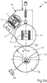
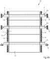
- FIGS. 1a . 1b . 3a . 3b and 4a are machining units 10 with three processing cylinders 11, 12, 13 shown in alternative embodiments.
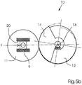
- FIGS. 5a and 5b Machining works 10 are shown with two processing cylinders 11, 12 in alternative embodiments. Common to all embodiments is the use of spiral support members 14.
- the cylinders 11, 12, 13 are preferably rotatably mounted on the respective axes of rotation 16 by means of rolling bearings (not shown).
- the support members 14, 15 are supported by these axles 16.
- FIG. 1a shows a first embodiment of a processing unit 10 according to the invention with three processing cylinders 11, 12, 13. This may be, for example, a printing unit 110, as in FIG. 6 is shown.
- the second processing cylinder 12 and the third processing cylinder 13 each spiral support 14 are assigned.
- the first processing cylinder 11 are also Assigned supporting body 15, which may for example be designed as support rings, but in FIG. 1a are not shown.
- the spiral support 14 act together with the supporting bodies 15, not shown, of the first cylinder 11.
- FIG. 1b shows the contact points 22 are respectively designated between the spiral support body 14 and the support body 15 of the first cylinder. Analogous to in FIG.
- the first cylinder 11 is mounted in a pivotable about a pivot point 21 linear guide 20.
- the second cylinder 12 and the third cylinder 13 are stationarily mounted in the machine frame 9. If the gap between the cylinders 11, 12, 13, ie, the distance between the first cylinder 11 and the second cylinder 12 and between the first cylinder 11 and third cylinder 13 are changed, the disk-shaped spiral support 14 are rotated, which is a movement of the first cylinder 11 in its suspension 20, 21 causes. If the first cylinder 11 is to be replaced by a smaller cylinder 11 ', for example for adaptation of the format when the first cylinder 11 or 11' is the pressure cylinder, then the first cylinder 11 'of smaller diameter assumes the in FIG.
- a biasing force F is applied.
- a power-operated actuator 19 is provided for hiring and parking the cylinder and for generating a biasing force.
- FIG. 3a is a manual adjusting device 18 for rotating the spiral support 14 indicated in FIG. 3b a motorized adjustment device 18.
- the spiral support members 14 are annular or disk-shaped in the form of a circular spiral 17 with a constant pitch.
- the outer contour of the spiral support body 14, which represents the surface in contact with the support bodies 15 of the first cylinder 11, has the shape of a constant spiral circular spiral, that is, the shape of an Arithmetic or Archimedean spiral.
- the spiral support body 14 is formed only partial circular, ie, includes only a portion or a segment of the entire circular spiral 17, in the illustrated embodiment of about 125 °.
- FIG. 1a shows an embodiment of the processing unit 10 with two stationary mounted in the machine frame 9 cylinders 12, 13 and a bearing means of linear guide 20 and pivot 21 in the machine frame 9 cylinder 11.
- the cylinder 11 is supported only by means of a linear guide 20.
- the cylinders 11 and 13 are mounted in a common bearing plate.
- first cylinder 11 and third cylinder 13 are arranged in a horizontal and first cylinder 11 and second cylinder 12 with their axes 16 in a vertical.
- the two cylinders 11 and 13 are movably mounted in the linear guide 20.
- the axes of rotation 16 of all cylinders 11, 12, 13 are arranged in a vertical.
- FIG. 5a A corresponding arrangement shows FIG. 5a for the use of only two cylinders 11, 12.
- FIG. 5b A 90 ° rotated arrangement, according to which the axes 16 of the first cylinder 11 and the second cylinder 12 are arranged in a horizontal, is in FIG. 5b shown.
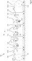
- FIG. 6 Figure 11 is a view of a preferred embodiment of a printing machine 100, more specifically, a narrow web label printing machine in a series construction, with printing units 110 following in the horizontal direction.
- the label printing machine is used to process a substrate 1000 in web form.
- the substrate is unrolled from a substrate roll 146 in a feed section 148 of the printing press 142 and fed through a press machine 142 along a machine direction M path.
- the printing press 142 may comprise a plurality of frame modules 126, here by way of example three frame modules 126, which together form the machine frame 9.
- two printing units 110 or a printing unit 110 and a processing unit 150 in this case a punching unit for punching out the labels on the web-shaped substrate 100, are received on a rack module 126.
- a processing unit 150 in this case a punching unit for punching out the labels on the web-shaped substrate 100
- rack module 126 After the individual processing stations follows an outlet part 152, in which the finished products are wound up in a label roll 154.
- Feeding part 148, rack modules 126 and outlet part 152 are detachably connected to each other so that a modular structure of the printing press 142 results.
- the printing units 110 in addition to the printing cylinders, the impression cylinders and the inking rollers and chamber doctor blade are shown. Furthermore, the printing units 110 in the printing press 100 have various drying devices: The counterpressure cylinders are assigned downstream of the respective printing gap of the printing unit 110 UV drying devices, so that the printed substrate 1000 can be dried directly on the impression cylinder.
- the printing units 110 also have web guiding rollers 160 for guiding the web-shaped substrate 1000.
- the fifth printing unit 110 comprises a hot air drying device 162. Alternatively, a UV or an IR drying device could also be used here.
- a punching unit 150 which has a punching cylinder and a counter-punching cylinder as rotating tools.
- a stamping mill for example a hot foil stamping mill.
- gravure printing, offset printing units and rotary screen printing units it is also possible to use gravure printing, offset printing units and rotary screen printing units.
- At least one of the printing units 110 or the stamping unit 150 have the structure of the above-described processing plants 10.
Landscapes
- Engineering & Computer Science (AREA)
- Mechanical Engineering (AREA)
- Rotary Presses (AREA)
Description
- Die Erfindung betrifft ein Bearbeitungswerk zur rotativen Bearbeitung mit den oberbegrifflichen Merkmalen von Anspruch 1 sowie eine Etikettendruckmaschine mit einem solchen Bearbeitungswerk gemäß Anspruch 6.
- Bei Etikettendruckmaschinen, wie sie z.B. in der
EP 2 103 429 B1 beschrieben sind kommen Druckwerke und Stanzwerke zum Einsatz. Die Druckwerke umfassen mindestens drei Zylinder, nämlich Farbauftragswalze, Druckzylinder und Gegendruckzylinder. Die rotative Bearbeitung bewirkt hierbei ein Aufbringen von Farbe auf ein Substrat. Die Stanzwerke umfassen mindestens zwei Zylinder, nämlich Stanzzylinder und Stanzgegenzylinder. Die rotative Bearbeitung bewirkt hierbei ein Einbringen von Stanz- und/oder Rilllinien. Zur Anpassung an das zu verarbeitende Substrat sowie zur Einstellung der Stanztiefe muss der Spalt, d.h. der Abstand zwischen den Zylindern einstellbar sein. Dazu werden Stützkörper verwendet, welche als Laufringe, Stützringe und als sogenannte Schmitzringe ausgebildet sein können. Beispiele für Einstelleinrichtungen finden sich in derDE 10 2005 015 046 A1 und derWO 2012/016758 A1 .
Nachteilig an derartigen Einstelleinrichtungen ist zum einen deren komplizierter und aufwändiger Aufbau. Zum anderen lässt die Einstellgenauigkeit zu wünschen übrig. Daraus ergibt sich auch eine schlechte Wiederholgenauigkeit. D.h. soll für einen Wiederholauftrag exakt dasselbe Spaltmaß wie bei dessen letzter Ausführung gewählt werden, so gestaltet sich eine derart exakte Einstellung schwierig. - Aufgabe der vorliegenden Erfindung ist es daher ein Bearbeitungswerk und eine Etikettendruckmaschine mit einem solchen Bearbeitungswerk zu schaffen, bei welcher das Spaltmaß zwischen den Bearbeitungszylindern des Bearbeitungswerks einfach, exakt und wiederholgenau einstellbar ist.
- Gelöst wird diese Aufgabe durch ein Bearbeitungswerk mit den Merkmalen von Anspruch 1. Das erfindungsgemäße Bearbeitungswerk zur rotativen Bearbeitung eines bahnförmigen oder bogenförmigen Substrats mit mindestens zwei rotierbaren Bearbeitungszylindern und einem Maschinengestell besitzt einen ersten Zylinder, welcher beweglich, insbesondere verschieblich, im Maschinengestell gelagert ist und einen zweiten, mit dem ersten zusammenwirkenden Zylinder, welcher stationär im Maschinengestell gelagert ist. Jedem Zylinder sind Stützkörper zugeordnet, wobei insbesondere ein Paar von auf der Rotationsachse angeordneter Stützkörper vorgesehen ist, wobei die Stützkörper zusammenwirken zur Abstützung der Zylinder gegeneinander. In vorteilhafter Weise sind die Stützkörper des zweiten Zylinders als Spiralstützkörper als verdrehbare, ring- bzw. scheibenförmige Körper in Form einer Kreisspirale mit konstanter Steigung ausgeformt. Das heißt, die Spiralstützkörper haben die Form einer sogenannten arithmetischen bzw. archimedischen Spirale. Die Steigung der Spirale ist abhängig vom zu verstellenden Weg und der gewünschten Verstellauflösung auszuwählen. Die Verwendung derartiger Spiralstützkörper hat den Vorteil, dass ein lineares, präzises Verstellverhalten des Spaltmaßes ermöglicht wird. Die Spiralstützkörper weisen dabei einen einfachen und kostengünstigen Aufbau auf. Durch die erfindungsgemäße Zuordnung der Spiralstützkörper zum zweiten Zylinder wird ein vorteilhafter Kraftfluss erreicht, welcher die Aufnahme hoher Kräfte erlaubt.
- Erfindungsgemäß weist das Bearbeitungswerk einen dritten Zylinder auf, wobei jeweils erster und zweiter sowie erster und dritter Zylinder tangieren, d. h. in Wirkkontakt zueinander stehen. Diesem dritten Zylinder sind ebenfalls Spiralstützkörper zugeordnet, die den gleichen Aufbau haben wie die Spiralstützkörper des zweiten Zylinders. Während ein Bearbeitungswerk mit zwei Bearbeitungszylindern beispielsweise als Stanz- bzw. Prägewerk eingesetzt werden kann, kann ein Bearbeitungswerk mit drei Bearbeitungszylindern als Druckwerk eingesetzt werden.
- In der erfindungsgemäßen Ausgestaltung des Bearbeitungswerks ist der dritte Bearbeitungszylinder stationär im Maschinengestell gelagert und der erste Bearbeitungszylinder entlang einer Linearführung verschieblich und um einen Drehpunkt schwenkbar im Maschinengestell gelagert. Dadurch ergibt sich eine stabile Zweipunktanlage des Druckzylinders, welche die Verwendung von ersten Bearbeitungszylindern unterschiedlicher Durchmesser ermöglicht.
- In einer besonders vorteilhaften und daher bevorzugten Weiterbildung des erfindungsgemäßen Bearbeitungswerks ist ein jeweiliger Spiralstützkörper teilkreisförmig ausgeformt, d.h. der Spiralstützkörper wird nur durch ein Teilsegment einer Kreisspirale gebildet, z.B. durch einen Viertelkreis, einen Halbkreis oder einen dazwischen liegenden Teilkreis. Während ein kreisförmiger Spiralstützkörper einen größeren Verstellbereich zur Einstellung des Spaltmaßes zwischen den Zylindern eröffnet, ist der Verstellbereich eines teilkreisförmig ausgeformten Spiralstützkörpers zwar begrenzt, jedoch für die konkreten Erfordernisse ausreichend. Durch die Verwendung der teilkreisförmigen Ausgestaltung kann somit Material und Bauraum eingespart werden.
- Besonders vorteilhaft ist es, wenn jedem Zylinder mit Spiralstützkörpern eine Verstelleinrichtung zugeordnet ist zum Verdrehen der Spiralstützkörper relativ zur Rotationsachse des jeweiligen Bearbeitungszylinders, im Sinne einer Winkeleinstellung der Spiralstützkörper. Bei der Verstelleinrichtung kann es sich um eine manuell oder motorisch betätigbare Einrichtung handeln. Im Fall von paarweise einem Zylinder zugeordneten Spiralstützkörpern kann insbesondere jeder Spiralstützkörper einzeln verdrehbar und einstellbar sein zur Bewirkung einer Verschränkung der Bearbeitungszylinder.
- In Weiterbildung des Bearbeitungswerkes ist zumindest eine Betätigungseinrichtung vorgesehen zum An- und Abstellen der Bearbeitungszylinder und zum Aufbringen einer Vorspannkraft auf mindestens einen der Zylinder.
- In einer Ausgestaltung des Bearbeitungswerks sind die Stützkörper des ersten Bearbeitungszylinders als mit der Rotationsachse verbundene und darauf drehbar gelagerte ring- bzw. scheibenförmige Körper ausgeführt, insbesondere als sogenannte Stützringe. Diese Stützkörper des ersten Zylinders wirken zusammen mit den Spiralstüzkörpern des zweiten und gegebenenfalls des dritten Zylinders und stehen mit diesen in Wirkkontakt.
- In einer bevorzugten Ausführungsvariante des Bearbeitungswerks ist der erste Bearbeitungszylinder als Druckzylinder, der zweite Bearbeitungszylinder als Gegendruckzylinder und der dritte Zylinder als Farbauftragswalze, insbesondere als Rasterwalze ausgeführt. Das Bearbeitungswerk bildet somit ein Druckwerk, beispielsweise ein Flexodruckwerk, welches dem Bedrucken von bahnförmigen oder bogenförmigen Substraten dient.
- Gegenstand der Erfindung ist auch eine Etikettendruckmaschine mit mindestens einem wie vorstehend beschriebenen Bearbeitungswerk.
- Die beschriebene Erfindung und die beschriebenen vorteilhaften Weiterbildungen der Erfindung stellen auch in Kombination miteinander - soweit dies technisch sinnvoll ist - vorteilhafte Weiterbildungen der Erfindung dar.
- Hinsichtlich weiterer Vorteile und in konstruktiver und funktioneller Hinsicht vorteilhafter Ausgestaltungen der Erfindung wird auf die Unteransprüche sowie die Beschreibung von Ausführungsbeispielen unter Bezugnahme auf die beiliegenden Figuren verwiesen.
- Die Erfindung soll an Hand beigefügter Figuren noch näher erläutert werden. Einander entsprechende Elemente und Bauteile sind in den Figuren mit gleichen Bezugszeichen versehen. Zugunsten einer besseren Übersichtlichkeit der Figuren wurde auf eine maßstabsgetreue Darstellung verzichtet.
Es zeigen in schematischer Darstellung - Fig. 1 a und b
- ein erfindungsgemäßes Bearbeitungswerk mit drei Bearbeitungszylindern in zwei alternativen Ausführungsformen
- Fig. 2
- einen spiralförmigen Stützkörper
- Fig. 3 a und b
- zwei weitere Alternativen eines erfindungsgemäßen Bearbeitungswerks mit drei Bearbeitungszylindern
- Fig. 4 a und b
- eine weitere Alternative eines erfindungsgemäßen Bearbeitungswerks mit drei Bearbeitungszylindern in einer Ansicht und einer Schnittdarstellung
- Fig. 5 a und b
- ein Bearbeitungswerk mit zwei Bearbeitungszylindern in zwei alternativen Ausführungsformen
- Fig. 6
- eine erfindungsgemäße Etikettendruckmaschine
- In den
Figuren 1a ,1b ,3a ,3b und4a sind Bearbeitungswerke 10 mit drei Bearbeitungszylindern 11, 12, 13 in alternativen Ausführungsformen dargestellt.
In denFiguren 5a und5b sind Bearbeitungswerke 10 mit zwei Bearbeitungszylindern 11, 12 in alternativen Ausführungsformen dargestellt. Allen Ausführungsformen gemeinsam ist die Verwendung von Spiralstützkörpern 14. - Die Zylinder 11, 12, 13 werden bevorzugt mittels Wälzlagern (nicht dargestellt) auf den jeweiligen Rotationsachsen 16 rotierbar gelagert. Auch die Stützkörper 14, 15 werden von diesen Achsen 16 getragen.
-
Figur 1a zeigt eine erste Ausführungsform eines erfindungsgemäßen Bearbeitungswerks 10 mit drei Bearbeitungszylindern 11, 12, 13. Dabei kann es sich beispielsweise um ein Druckwerk 110 handeln, wie es inFigur 6 dargestellt ist. Dem zweiten Bearbeitungszylinder 12 und dem dritten Bearbeitungszylinder 13 sind jeweils Spiralstützkörper 14 zugeordnet. Dem ersten Bearbeitungszylinder 11 sind ebenfalls Stützkörper 15 zugeordnet, welche beispielsweise als Stützringe ausgeführt sein können, allerdings inFigur 1a nicht dargestellt sind. Die Spiralstützkörper 14 wirken zusammen mit den nicht dargestellten Stützkörpern 15 des ersten Zylinders 11. Das Zusammenwirken der Stützkörper 14, 15 ergibt sich ausFigur 1b , in welcher die Kontaktpunkte 22 jeweils zwischen Spiralstützkörper 14 und dem Stützkörper 15 des ersten Zylinders bezeichnet sind. Analog zur inFigur 4b dargestellten Ausführung, gemäß der die Spiralstützkörper 14 und die Stützkörper 15 jeweils stirnseitig zu den Zylindern 11, 12, 13 auf den Rotationsachsen 16 angeordnet sind, können die Spiralstützkörper 14 und die Stützkörper 15 auch in den Ausführungsvarianten gemäß derFiguren 1a ,1b ,3a ,3b ,5a und5b auf den Rotationsachsen 16 angeordnet sein. - In der Ausführungsvariante von
Figur 1a ist der erste Zylinder 11 in einer um einen Drehpunkt 21 schwenkbaren Linearführung 20 gelagert. Der zweite Zylinder 12 und der dritte Zylinder 13 sind stationär im Maschinengestell 9 gelagert. Soll das Spaltmaß zwischen den Zylindern 11, 12, 13, d. h. der Abstand zwischen erstem Zylinder 11 und zweitem Zylinder 12 bzw. zwischen erstem Zylinder 11 und drittem Zylinder 13 verändert werden, so werden die scheibenförmigen Spiralstützkörper 14 verdreht, was eine Bewegung des ersten Zylinders 11 in seiner Aufhängung 20, 21 bewirkt. Soll der erste Zylinder 11 durch einen kleineren Zylinder 11' ersetzt werden, beispielsweise zur Formatanpassung wenn es sich bei dem ersten Zylinder 11 bzw. 11' um den Druckzylinder handelt, so nimmt der erste Zylinder 11' mit kleinerem Durchmesser die inFigur 1a gezeigte Position ein und das Spaltmaß zwischen diesem ersten Zylinder11' und dem zweiten Zylinder 12 bzw. dem dritten Zylinder 13 kann ebenfalls mittels der Spiralstützkörper 14 eingestellt werden. Um eine sichere Anlage des ersten Zylinders 11 bzw. 11' am zweiten Zylinder 12 und dritten Zylinder 13 an den beiden inFigur 1b dargestellten Kontaktpunkten 22 sicher zu stellen, wird eine Vorspannkraft F aufgebracht. Dazu ist eine kraftbetätigte Betätigungseinrichtung 19 vorgesehen zum Anstellen und Abstellen der Zylinder sowie zum Erzeugen einer Vorspannkraft. In den Ausführungsvarianten gemäßFigur 3a und3b ist eine solche Betätigungseinrichtung 19 angedeutet. InFigur 3a ist eine manuelle Verstelleinrichtung 18 zum Verdrehen der Spiralstützkörper 14 angedeutet, inFigur 3b eine motorische Verstelleinrichtung 18. - Die Wirkweise der Abstandseinstellung sowie die Ausgestaltung der Spiralstützkörper 14 ergibt sich aus
Figur 2 : Die Spiralstützkörper 14 sind ring- bzw. scheibenförmig in Form einer Kreisspirale 17 mit konstanter Steigung ausgebildet. In anderen Worten: Die Außenkontur der Spiralstützkörper 14, welche die mit den Stützkörpern 15 des ersten Zylinders 11 in Kontakt stehende Fläche darstellt, hat die Form einer Kreisspirale mit konstanter Steigung, d. h. die Form einer arithmetischen bzw. archimedischen Spirale. Wie es sich ausFigur 2 ergibt, ist der Spiralstützkörper 14 nur teilkreisförmig ausgeformt, d. h. umfasst nur einen Teil bzw. ein Segment der ganzen Kreisspirale 17, im dargestellten Ausführungsbeispiel von ca. 125°. Durch eine Drehbewegung d der Spiralstützkörper 14, welche durch eine Verstelleinrichtung 18 realisiert wird, wird der Radius r zwischen der Rotationsachse 16 und dem Kontaktpunkt 22 verändert, wie dies exemplarisch inFigur 3a eingezeichnet ist. -
Figur 1a zeigt eine Ausführung des Bearbeitungswerks 10 mit zwei stationär im Maschinengestell 9 gelagerten Zylindern 12, 13 und einem mittels Linearführung 20 und Drehpunkt 21 im Maschinengestell 9 gelagerten Zylinder 11. Bei der Ausführungsform gemäßFigur 1b ist der Zylinder 11 nur mittels einer Linearführung 20 gelagert. In der Ausführungsform vonFigur 3a sind die Zylinder 11 und 13 in einer gemeinsamen Lagerplatte gelagert. So können die Zylinder 11 und 13 relativ zueinander und gemeinsam zum Zylinder 12 bewegt werden. Die Lagerung der Ausführungsform gemäßFigur 3b ist ähnlich, wobei erster Zylinder 11 und dritter Zylinder 13 in einer Horizontalen und erster Zylinder 11 und zweiter Zylinder 12 mit ihren Achsen 16 in einer Vertikalen angeordnet sind. In der Ausführungsform gemäßFigur 4a ist nur der zweite Zylinder 12 stationär im Maschinengestell 9 gelagert, die beiden Zylinder 11 und 13 sind in Linearführung 20 beweglich gelagert. Die Rotationsachsen 16 aller Zylinder 11, 12, 13 sind dabei in einer Vertikalen angeordnet. - Eine entsprechende Anordnung zeigt
Figur 5a für die Verwendung von nur zwei Zylindern 11, 12. Eine um 90° gedrehte Anordnung, gemäß welcher die Achsen 16 von erstem Zylinder 11 und zweitem Zylinder 12 in einer Horizontalen angeordnet sind, ist inFigur 5b dargestellt. - In der
Figur 6 ist eine Ansicht einer bevorzugten Ausführungsform einer Druckmaschine 100, genauer einer Schmalbahn-Etikettendruckmaschine in Reihenbauweise, mit in horizontaler Richtung folgenden Druckwerken 110 gezeigt. Die Etikettendruckmaschine dient der Bearbeitung eines Substrats 1000 in Bahnform. Das Substrat wird von einer Substratrolle 146 in einem Zuführteil 148 der Druckmaschine 142 abgerollt und entlang eines Weges in Maschinenlaufrichtung M durch die Druckmaschine 142 geführt. Die Druckmaschine 142 kann eine Mehrzahl von Gestellmodulen 126, hier beispielhaft drei Gestellmodule 126, aufweisen, welche zusammen das Maschinengestell 9 bilden. In dieser Ausführungsform sind jeweils zwei Druckwerke 110 beziehungsweise ein Druckwerk 110 und ein Bearbeitungswerk 150, hier ein Stanzwerk zum Ausstanzen der Etiketten auf dem bahnförmigen Substrat 100, an einem Gestellmodul 126 aufgenommen. Nach den einzelnen Bearbeitungsstationen folgt ein Auslaufteil 152, in welchem die fertigen Produkte in eine Etikettenrolle 154 aufgewickelt werden. Zuführteil 148, Gestellmodule 126 und Auslaufteil 152 sind lösbar bzw. trennbar miteinander verbunden sodass sich ein modularer Aufbau der Druckmaschine 142 ergibt. - In der Darstellung der einzelnen Druckwerke 110, hier Flexodruckwerke sind neben den Druckzylindern, den Gegendruckzylindern und den Farbauftragswalzen auch Kammerrakel gezeigt. Des Weiteren weisen die Druckwerke 110 in der Druckmaschine 100 diverse Trocknungseinrichtungen auf: Den Gegendruckzylindern sind an dem jeweiligen Druckspalt des Druckwerks 110 nachgeordnet UV-Trocknungseinrichtungen zugeordnet, so dass das bedruckte Substrat 1000 direkt auf dem Gegendruckzylinder getrocknet werden kann. Die Druckwerke 110 weisen auch Bahnleitwalzen 160 zur Führung des bahnförmigen Substrats 1000 auf. In der gezeigten Ausführungsform umfasst das fünfte Druckwerk 110 eine Heißlufttrocknungseinrichtung 162. Alternativ könnte auch hier eine UV- oder eine IR-Trocknungseinrichtung eingesetzt werden. Nachfolgend ist ein Stanzwerk 150 angeordnet, welches als rotierende Werkzeuge einen Stanzzylinder und einen Gegenstanzzylinder aufweist. Zusätzlich bzw. alternativ zu dem Stanzwerk kann auch ein Prägewerk, beispielsweise ein Heißfolienprägewerk Verwendung finden. Alternativ zu den dargestellten Flexodruckwerken können auch Tiefdruck-, Offset-Druckwerke und Rotationssiebdruckwerke eingesetzt werden.
- Zumindest eines der Druckwerke 110 oder das Stanzwerk 150 haben dabei den Aufbau der obenstehend beschriebenen Bearbeitungswerke 10.
-
- 9
- Maschinengestell
- 10
- Bearbeitungswerk
- 11
- erster Zylinder
- 11'
- erster Zylinder mit kleinerem Durchmesser
- 12
- zweiter Zylinder
- 13
- dritter Zylinder
- 14
- Spiralstützkörper
- 15
- Stützkörper des 1. Zylinders (Stützringe)
- 16
- Rotationsachse
- 17
- Kreisspirale
- 18
- Verstelleinrichtung
- 19
- Betätigungseinrichtung
- 20
- Linearführung
- 21
- Drehpunkt
- 22
- Kontaktpunkt
- 23
- Steuereinrichtung
- 100
- Druckmaschine
- 110
- Druckwerk
- 126
- Gestellmodul
- 146
- Substratrolle
- 148
- Zuführstation
- 150
- Stanzwerk
- 152
- Auslaufstation
- 154
- Etikettenrolle
- 160
- Bahnleitwalze
- 162
- Heißlufttrockner
- 1000
- Substrat
- F
- Vorspannkraft
- M
- Maschinenlaufrichtung
- d
- Drehbewegung
Claims (6)
- Bearbeitungswerk (10) zur rotativen Bearbeitung eines bahnförmigen oder bogenförmigen Substrats (1000) mit drei Bearbeitungszylindern (11, 12, 13) und einem Maschinengestell (9),
wobei ein erster Bearbeitungszylinder (11) ausgeführt als Druckzylinder beweglich im Maschinengestell (9), und ein zweiter Bearbeitungszylinder (12) ausgeführt als Gegendruckzylinder und eine dritter Bearbeitungszylinder (13) ausgeführt als Farbauftragswalze stationär im Maschinengestell (9) gelagert sind, wobei jedem Bearbeitungszylinder (11, 12, 13) Stützkörper (14, 15) zugeordnet sind,
wobei der erste Bearbeitungszylinder (11) entlang einer Linearführung (20) verschieblich und um einen Drehpunkt (21) schwenkbar im Maschinengestell (9) gelagert ist,
dadurch gekennzeichnet,
dass die Stützkörper (14) des zweiten Bearbeitungszylinders (12) und des dritten Bearbeitungsyzlinders (13) als Spiralstützkörper als verdrehbare (d), ring- oder scheibenförmige Körper in Form einer Kreisspirale (17) mit konstanter Steigung ausgeformt sind. - Bearbeitungswerk nach einem der vorangehenden Ansprüche,
dadurch gekennzeichnet,
dass ein jeweiliger Spiralstützkörper (14) teilkreisförmig ausgeformt ist. - Bearbeitungswerk nach einem der vorangehenden Ansprüche,
dadurch gekennzeichnet,
dass jedem Bearbeitungszylinder (12, 13) mit Spiralstützkörpern (14) eine Verstelleinrichtung (18) zugeordnet ist zum Verdrehen der Spiralstützkörper (14) relativ zur Rotationsachse (16) des jeweiligen Bearbeitungszylinders (12, 13). - Bearbeitungswerk nach einem der vorangehenden Ansprüche,
dadurch gekennzeichnet,
dass zumindest eine Betätigungseinrichtung (19) vorgesehen ist zum An- und Abstellen mindestens eines der Zylinder (11, 12, 13) und zum Aufbringen einer Vorspannkraft (F). - Bearbeitungswerk nach einem der vorangehenden Ansprüche,
dadurch gekennzeichnet,
dass die Stützkörper (15) des ersten Bearbeitungszylinders (11) als mit der Rotationsachse (16) des ersten Bearbeitungszylinders (11) verbundene ring- oder scheibenförmige Körper ausgeführt sind. - Etikettendruckmaschine (100) mit mindestens einem Bearbeitungswerk (10) nach einem der vorangehenden Ansprüche.
Applications Claiming Priority (1)
| Application Number | Priority Date | Filing Date | Title |
|---|---|---|---|
| DE102015212572.6A DE102015212572A1 (de) | 2015-07-06 | 2015-07-06 | Bearbeitungswerk zur rotativen Bearbeitung |
Publications (2)
| Publication Number | Publication Date |
|---|---|
| EP3115203A1 EP3115203A1 (de) | 2017-01-11 |
| EP3115203B1 true EP3115203B1 (de) | 2018-01-31 |
Family
ID=56344975
Family Applications (1)
| Application Number | Title | Priority Date | Filing Date |
|---|---|---|---|
| EP16173855.4A Not-in-force EP3115203B1 (de) | 2015-07-06 | 2016-06-10 | Bearbeitungswerk zur rotativen bearbeitung |
Country Status (2)
| Country | Link |
|---|---|
| EP (1) | EP3115203B1 (de) |
| DE (1) | DE102015212572A1 (de) |
Families Citing this family (3)
| Publication number | Priority date | Publication date | Assignee | Title |
|---|---|---|---|---|
| DE102016215986A1 (de) * | 2016-08-25 | 2018-03-01 | Gallus Druckmaschinen Gmbh | Bearbeitungswerk und Etikettendruckmaschine mit einem solchen Bearbeitungswerk |
| DE102016215988A1 (de) * | 2016-08-25 | 2018-03-01 | Gallus Druckmaschinen Gmbh | Bearbeitungswerk und Etikettendruckmaschine mit einem solchen Bearbeitungswerk |
| DE102017216793A1 (de) * | 2017-09-22 | 2019-03-28 | Gallus Druckmaschinen Gmbh | Vorrichtung zur Bearbeitung eines bahnförmigen oder bogenförmigen Substrats |
Family Cites Families (5)
| Publication number | Priority date | Publication date | Assignee | Title |
|---|---|---|---|---|
| DE3317746C2 (de) * | 1983-05-16 | 1986-10-09 | Jürgen 1000 Berlin Schulz | Druckwerk und Verfahren zum Drucken |
| DE102005015046A1 (de) | 2005-03-31 | 2006-10-05 | Gallus Ferd. Rüesch AG | Farbauftragswalze für ein Offsetdruckwerk |
| DE102007045876A1 (de) * | 2007-09-25 | 2009-04-09 | Gallus Druckmaschinen Gmbh | Druckwerk und Druckmaschine |
| DE102008013315A1 (de) | 2008-03-10 | 2009-09-17 | Gallus Druckmaschinen Gmbh | Druckwerk und Druckmaschine |
| IT1401510B1 (it) | 2010-08-03 | 2013-07-26 | Nuova Gidue S R L | Gruppo di stampa perfezionato, particolarmente per stampe flessografiche con cilindro di stampa rimovibile. |
-
2015
- 2015-07-06 DE DE102015212572.6A patent/DE102015212572A1/de not_active Withdrawn
-
2016
- 2016-06-10 EP EP16173855.4A patent/EP3115203B1/de not_active Not-in-force
Non-Patent Citations (1)
| Title |
|---|
| None * |
Also Published As
| Publication number | Publication date |
|---|---|
| EP3115203A1 (de) | 2017-01-11 |
| DE102015212572A1 (de) | 2017-01-12 |
Similar Documents
| Publication | Publication Date | Title |
|---|---|---|
| DE102007005340B4 (de) | Druckverfahren und Vorrichtung zum Bedrucken von Hohlkörpern | |
| EP2103429B1 (de) | Druckwerk und Druckmaschine mit Formatänderung | |
| EP2100733A1 (de) | Modular aufgebaute Lineardruckmaschine zum Bedrucken von Hohlkörpern mit unterschiedlichen Druckverfahren | |
| DE102004004665B4 (de) | Vorrichtung zum Einstellen einer von einer Walze in einem Walzenstreifen auf einen benachbarten Rotationskörper ausgeübten Anpresskraft und zum Anstellen der Walze an den Rotationskörper oder zum Abstellen der Walze von dem Rotationskörper | |
| EP3115203A1 (de) | Bearbeitungswerk zur rotativen bearbeitung | |
| EP2551078B1 (de) | Vorrichtung zum Stanzen mit einstellbarem Zylinderabstand | |
| EP3287281B1 (de) | Bearbeitungswerk und etikettendruckmaschine mit einem solchen bearbeitungswerk | |
| EP3287280B1 (de) | Bearbeitungswerk und etikettendruckmaschine mit einem solchen bearbeitungswerk | |
| EP2464518A1 (de) | Rotationssiebdruckvorrichtung und -verfahren | |
| EP3196021A1 (de) | Vorrichtung zum heissfolienprägen | |
| EP0512267A2 (de) | Kaschiermaschine | |
| DE102011108954A1 (de) | Vorrichtung zum Stanzen mit hydrostatischer Zylinderlagerung | |
| DE10244046B4 (de) | Vorrichtung zum Einstellen des Anpressdrucks einer verstellbar gelagerten Walze | |
| EP3459738A1 (de) | Vorrichtung zur bearbeitung eines bahnförmigen oder bogenförmigen substrats | |
| EP1989052B1 (de) | Druckmaschine | |
| EP3411236B1 (de) | Druckmaschine und verfahren zum trocknen eines bandmaterials einer druckmaschine | |
| DE3148667C1 (de) | Vorrichtung zum Druckmittelaustausch zwischen, in Walzenlängsrichtung zueinander versetzten Zonen im Farbwerk einer Rotationsdruckmaschine | |
| DE2953287A1 (en) | Motion translation apparatus | |
| DE102005027543B3 (de) | Rollenrotationshochdruckmaschine | |
| DE10210561B4 (de) | Vorrichtung zum Einstellen und Halten der Abstände der Gummituchzylinder einer Mehrzahl von Druckwerken einer Satelliten- Bogenrotationsdruckeinheit zu einem gemeinsamen Gegendruckzylinder | |
| EP3235641B1 (de) | Bearbeitungsmaschine mit freigebbarem bearbeitungszylinder | |
| DE102006061394B4 (de) | Farbwerk einer Druckmaschine | |
| DE2337257C3 (de) | Rotationsdruckwerk zum Bedrucken unebener Körper | |
| AT9035U1 (de) | Vorrichtung zum auftragen eines mittels auf bahnförmiges material, insbesondere zum beschichten, imprägnieren und drucken | |
| DE3131392A1 (de) | "vorrichtung zum winkelsynchronen drehen wenigstens zweier koerper, insbesondere fuer teile von druckmaschinen od.dgl." |
Legal Events
| Date | Code | Title | Description |
|---|---|---|---|
| PUAI | Public reference made under article 153(3) epc to a published international application that has entered the european phase |
Free format text: ORIGINAL CODE: 0009012 |
|
| STAA | Information on the status of an ep patent application or granted ep patent |
Free format text: STATUS: THE APPLICATION HAS BEEN PUBLISHED |
|
| AK | Designated contracting states |
Kind code of ref document: A1 Designated state(s): AL AT BE BG CH CY CZ DE DK EE ES FI FR GB GR HR HU IE IS IT LI LT LU LV MC MK MT NL NO PL PT RO RS SE SI SK SM TR |
|
| AX | Request for extension of the european patent |
Extension state: BA ME |
|
| STAA | Information on the status of an ep patent application or granted ep patent |
Free format text: STATUS: REQUEST FOR EXAMINATION WAS MADE |
|
| 17P | Request for examination filed |
Effective date: 20170711 |
|
| RBV | Designated contracting states (corrected) |
Designated state(s): AL AT BE BG CH CY CZ DE DK EE ES FI FR GB GR HR HU IE IS IT LI LT LU LV MC MK MT NL NO PL PT RO RS SE SI SK SM TR |
|
| GRAP | Despatch of communication of intention to grant a patent |
Free format text: ORIGINAL CODE: EPIDOSNIGR1 |
|
| STAA | Information on the status of an ep patent application or granted ep patent |
Free format text: STATUS: GRANT OF PATENT IS INTENDED |
|
| RIC1 | Information provided on ipc code assigned before grant |
Ipc: B41F 13/28 20060101ALI20170816BHEP Ipc: B41F 13/24 20060101AFI20170816BHEP |
|
| INTG | Intention to grant announced |
Effective date: 20170906 |
|
| GRAS | Grant fee paid |
Free format text: ORIGINAL CODE: EPIDOSNIGR3 |
|
| GRAA | (expected) grant |
Free format text: ORIGINAL CODE: 0009210 |
|
| STAA | Information on the status of an ep patent application or granted ep patent |
Free format text: STATUS: THE PATENT HAS BEEN GRANTED |
|
| AK | Designated contracting states |
Kind code of ref document: B1 Designated state(s): AL AT BE BG CH CY CZ DE DK EE ES FI FR GB GR HR HU IE IS IT LI LT LU LV MC MK MT NL NO PL PT RO RS SE SI SK SM TR |
|
| REG | Reference to a national code |
Ref country code: GB Ref legal event code: FG4D Free format text: NOT ENGLISH Ref country code: CH Ref legal event code: EP |
|
| REG | Reference to a national code |
Ref country code: AT Ref legal event code: REF Ref document number: 966974 Country of ref document: AT Kind code of ref document: T Effective date: 20180215 |
|
| REG | Reference to a national code |
Ref country code: IE Ref legal event code: FG4D Free format text: LANGUAGE OF EP DOCUMENT: GERMAN |
|
| REG | Reference to a national code |
Ref country code: DE Ref legal event code: R096 Ref document number: 502016000537 Country of ref document: DE |
|
| REG | Reference to a national code |
Ref country code: NL Ref legal event code: MP Effective date: 20180131 |
|
| REG | Reference to a national code |
Ref country code: LT Ref legal event code: MG4D |
|
| PG25 | Lapsed in a contracting state [announced via postgrant information from national office to epo] |
Ref country code: HR Free format text: LAPSE BECAUSE OF FAILURE TO SUBMIT A TRANSLATION OF THE DESCRIPTION OR TO PAY THE FEE WITHIN THE PRESCRIBED TIME-LIMIT Effective date: 20180131 Ref country code: FI Free format text: LAPSE BECAUSE OF FAILURE TO SUBMIT A TRANSLATION OF THE DESCRIPTION OR TO PAY THE FEE WITHIN THE PRESCRIBED TIME-LIMIT Effective date: 20180131 Ref country code: ES Free format text: LAPSE BECAUSE OF FAILURE TO SUBMIT A TRANSLATION OF THE DESCRIPTION OR TO PAY THE FEE WITHIN THE PRESCRIBED TIME-LIMIT Effective date: 20180131 Ref country code: NO Free format text: LAPSE BECAUSE OF FAILURE TO SUBMIT A TRANSLATION OF THE DESCRIPTION OR TO PAY THE FEE WITHIN THE PRESCRIBED TIME-LIMIT Effective date: 20180430 Ref country code: LT Free format text: LAPSE BECAUSE OF FAILURE TO SUBMIT A TRANSLATION OF THE DESCRIPTION OR TO PAY THE FEE WITHIN THE PRESCRIBED TIME-LIMIT Effective date: 20180131 Ref country code: NL Free format text: LAPSE BECAUSE OF FAILURE TO SUBMIT A TRANSLATION OF THE DESCRIPTION OR TO PAY THE FEE WITHIN THE PRESCRIBED TIME-LIMIT Effective date: 20180131 |
|
| PG25 | Lapsed in a contracting state [announced via postgrant information from national office to epo] |
Ref country code: GR Free format text: LAPSE BECAUSE OF FAILURE TO SUBMIT A TRANSLATION OF THE DESCRIPTION OR TO PAY THE FEE WITHIN THE PRESCRIBED TIME-LIMIT Effective date: 20180501 Ref country code: PL Free format text: LAPSE BECAUSE OF FAILURE TO SUBMIT A TRANSLATION OF THE DESCRIPTION OR TO PAY THE FEE WITHIN THE PRESCRIBED TIME-LIMIT Effective date: 20180131 Ref country code: IS Free format text: LAPSE BECAUSE OF FAILURE TO SUBMIT A TRANSLATION OF THE DESCRIPTION OR TO PAY THE FEE WITHIN THE PRESCRIBED TIME-LIMIT Effective date: 20180531 Ref country code: SE Free format text: LAPSE BECAUSE OF FAILURE TO SUBMIT A TRANSLATION OF THE DESCRIPTION OR TO PAY THE FEE WITHIN THE PRESCRIBED TIME-LIMIT Effective date: 20180131 Ref country code: LV Free format text: LAPSE BECAUSE OF FAILURE TO SUBMIT A TRANSLATION OF THE DESCRIPTION OR TO PAY THE FEE WITHIN THE PRESCRIBED TIME-LIMIT Effective date: 20180131 Ref country code: RS Free format text: LAPSE BECAUSE OF FAILURE TO SUBMIT A TRANSLATION OF THE DESCRIPTION OR TO PAY THE FEE WITHIN THE PRESCRIBED TIME-LIMIT Effective date: 20180131 Ref country code: BG Free format text: LAPSE BECAUSE OF FAILURE TO SUBMIT A TRANSLATION OF THE DESCRIPTION OR TO PAY THE FEE WITHIN THE PRESCRIBED TIME-LIMIT Effective date: 20180430 |
|
| PG25 | Lapsed in a contracting state [announced via postgrant information from national office to epo] |
Ref country code: MT Free format text: LAPSE BECAUSE OF FAILURE TO SUBMIT A TRANSLATION OF THE DESCRIPTION OR TO PAY THE FEE WITHIN THE PRESCRIBED TIME-LIMIT Effective date: 20180131 |
|
| PG25 | Lapsed in a contracting state [announced via postgrant information from national office to epo] |
Ref country code: EE Free format text: LAPSE BECAUSE OF FAILURE TO SUBMIT A TRANSLATION OF THE DESCRIPTION OR TO PAY THE FEE WITHIN THE PRESCRIBED TIME-LIMIT Effective date: 20180131 Ref country code: IT Free format text: LAPSE BECAUSE OF FAILURE TO SUBMIT A TRANSLATION OF THE DESCRIPTION OR TO PAY THE FEE WITHIN THE PRESCRIBED TIME-LIMIT Effective date: 20180131 Ref country code: RO Free format text: LAPSE BECAUSE OF FAILURE TO SUBMIT A TRANSLATION OF THE DESCRIPTION OR TO PAY THE FEE WITHIN THE PRESCRIBED TIME-LIMIT Effective date: 20180131 Ref country code: AL Free format text: LAPSE BECAUSE OF FAILURE TO SUBMIT A TRANSLATION OF THE DESCRIPTION OR TO PAY THE FEE WITHIN THE PRESCRIBED TIME-LIMIT Effective date: 20180131 |
|
| REG | Reference to a national code |
Ref country code: DE Ref legal event code: R097 Ref document number: 502016000537 Country of ref document: DE |
|
| PG25 | Lapsed in a contracting state [announced via postgrant information from national office to epo] |
Ref country code: CZ Free format text: LAPSE BECAUSE OF FAILURE TO SUBMIT A TRANSLATION OF THE DESCRIPTION OR TO PAY THE FEE WITHIN THE PRESCRIBED TIME-LIMIT Effective date: 20180131 Ref country code: SK Free format text: LAPSE BECAUSE OF FAILURE TO SUBMIT A TRANSLATION OF THE DESCRIPTION OR TO PAY THE FEE WITHIN THE PRESCRIBED TIME-LIMIT Effective date: 20180131 Ref country code: DK Free format text: LAPSE BECAUSE OF FAILURE TO SUBMIT A TRANSLATION OF THE DESCRIPTION OR TO PAY THE FEE WITHIN THE PRESCRIBED TIME-LIMIT Effective date: 20180131 Ref country code: SM Free format text: LAPSE BECAUSE OF FAILURE TO SUBMIT A TRANSLATION OF THE DESCRIPTION OR TO PAY THE FEE WITHIN THE PRESCRIBED TIME-LIMIT Effective date: 20180131 |
|
| PLBE | No opposition filed within time limit |
Free format text: ORIGINAL CODE: 0009261 |
|
| STAA | Information on the status of an ep patent application or granted ep patent |
Free format text: STATUS: NO OPPOSITION FILED WITHIN TIME LIMIT |
|
| 26N | No opposition filed |
Effective date: 20181102 |
|
| PG25 | Lapsed in a contracting state [announced via postgrant information from national office to epo] |
Ref country code: SI Free format text: LAPSE BECAUSE OF FAILURE TO SUBMIT A TRANSLATION OF THE DESCRIPTION OR TO PAY THE FEE WITHIN THE PRESCRIBED TIME-LIMIT Effective date: 20180131 |
|
| REG | Reference to a national code |
Ref country code: BE Ref legal event code: MM Effective date: 20180630 |
|
| REG | Reference to a national code |
Ref country code: IE Ref legal event code: MM4A |
|
| PG25 | Lapsed in a contracting state [announced via postgrant information from national office to epo] |
Ref country code: LU Free format text: LAPSE BECAUSE OF NON-PAYMENT OF DUE FEES Effective date: 20180610 Ref country code: MC Free format text: LAPSE BECAUSE OF FAILURE TO SUBMIT A TRANSLATION OF THE DESCRIPTION OR TO PAY THE FEE WITHIN THE PRESCRIBED TIME-LIMIT Effective date: 20180131 |
|
| PG25 | Lapsed in a contracting state [announced via postgrant information from national office to epo] |
Ref country code: FR Free format text: LAPSE BECAUSE OF NON-PAYMENT OF DUE FEES Effective date: 20180630 Ref country code: IE Free format text: LAPSE BECAUSE OF NON-PAYMENT OF DUE FEES Effective date: 20180610 |
|
| PG25 | Lapsed in a contracting state [announced via postgrant information from national office to epo] |
Ref country code: BE Free format text: LAPSE BECAUSE OF NON-PAYMENT OF DUE FEES Effective date: 20180630 |
|
| PG25 | Lapsed in a contracting state [announced via postgrant information from national office to epo] |
Ref country code: TR Free format text: LAPSE BECAUSE OF FAILURE TO SUBMIT A TRANSLATION OF THE DESCRIPTION OR TO PAY THE FEE WITHIN THE PRESCRIBED TIME-LIMIT Effective date: 20180131 |
|
| PG25 | Lapsed in a contracting state [announced via postgrant information from national office to epo] |
Ref country code: PT Free format text: LAPSE BECAUSE OF FAILURE TO SUBMIT A TRANSLATION OF THE DESCRIPTION OR TO PAY THE FEE WITHIN THE PRESCRIBED TIME-LIMIT Effective date: 20180131 |
|
| PG25 | Lapsed in a contracting state [announced via postgrant information from national office to epo] |
Ref country code: HU Free format text: LAPSE BECAUSE OF FAILURE TO SUBMIT A TRANSLATION OF THE DESCRIPTION OR TO PAY THE FEE WITHIN THE PRESCRIBED TIME-LIMIT; INVALID AB INITIO Effective date: 20160610 Ref country code: CY Free format text: LAPSE BECAUSE OF FAILURE TO SUBMIT A TRANSLATION OF THE DESCRIPTION OR TO PAY THE FEE WITHIN THE PRESCRIBED TIME-LIMIT Effective date: 20180131 Ref country code: MK Free format text: LAPSE BECAUSE OF NON-PAYMENT OF DUE FEES Effective date: 20180131 |
|
| PGFP | Annual fee paid to national office [announced via postgrant information from national office to epo] |
Ref country code: CH Payment date: 20200618 Year of fee payment: 5 |
|
| PGFP | Annual fee paid to national office [announced via postgrant information from national office to epo] |
Ref country code: DE Payment date: 20200630 Year of fee payment: 5 |
|
| GBPC | Gb: european patent ceased through non-payment of renewal fee |
Effective date: 20200610 |
|
| PG25 | Lapsed in a contracting state [announced via postgrant information from national office to epo] |
Ref country code: GB Free format text: LAPSE BECAUSE OF NON-PAYMENT OF DUE FEES Effective date: 20200610 |
|
| REG | Reference to a national code |
Ref country code: DE Ref legal event code: R119 Ref document number: 502016000537 Country of ref document: DE |
|
| REG | Reference to a national code |
Ref country code: CH Ref legal event code: PL |
|
| PG25 | Lapsed in a contracting state [announced via postgrant information from national office to epo] |
Ref country code: LI Free format text: LAPSE BECAUSE OF NON-PAYMENT OF DUE FEES Effective date: 20210630 Ref country code: DE Free format text: LAPSE BECAUSE OF NON-PAYMENT OF DUE FEES Effective date: 20220101 Ref country code: CH Free format text: LAPSE BECAUSE OF NON-PAYMENT OF DUE FEES Effective date: 20210630 |
|
| REG | Reference to a national code |
Ref country code: AT Ref legal event code: MM01 Ref document number: 966974 Country of ref document: AT Kind code of ref document: T Effective date: 20210610 |
|
| PG25 | Lapsed in a contracting state [announced via postgrant information from national office to epo] |
Ref country code: AT Free format text: LAPSE BECAUSE OF NON-PAYMENT OF DUE FEES Effective date: 20210610 |