EP3115507A1 - Machine de travail du sol et procede de fonctionnement optimise contre l'usure d'une machine de travail du sol - Google Patents
Machine de travail du sol et procede de fonctionnement optimise contre l'usure d'une machine de travail du sol Download PDFInfo
- Publication number
- EP3115507A1 EP3115507A1 EP16175421.3A EP16175421A EP3115507A1 EP 3115507 A1 EP3115507 A1 EP 3115507A1 EP 16175421 A EP16175421 A EP 16175421A EP 3115507 A1 EP3115507 A1 EP 3115507A1
- Authority
- EP
- European Patent Office
- Prior art keywords
- machine
- wear
- parameter
- milling
- parameters
- Prior art date
- Legal status (The legal status is an assumption and is not a legal conclusion. Google has not performed a legal analysis and makes no representation as to the accuracy of the status listed.)
- Granted
Links
Images


Classifications
-
- E—FIXED CONSTRUCTIONS
- E01—CONSTRUCTION OF ROADS, RAILWAYS, OR BRIDGES
- E01C—CONSTRUCTION OF, OR SURFACES FOR, ROADS, SPORTS GROUNDS, OR THE LIKE; MACHINES OR AUXILIARY TOOLS FOR CONSTRUCTION OR REPAIR
- E01C23/00—Auxiliary devices or arrangements for constructing, repairing, reconditioning, or taking-up road or like surfaces
- E01C23/06—Devices or arrangements for working the finished surface; Devices for repairing or reconditioning the surface of damaged paving; Recycling in place or on the road
- E01C23/08—Devices or arrangements for working the finished surface; Devices for repairing or reconditioning the surface of damaged paving; Recycling in place or on the road for roughening or patterning; for removing the surface down to a predetermined depth high spots or material bonded to the surface, e.g. markings; for maintaining earth roads, clay courts or like surfaces by means of surface working tools, e.g. scarifiers, levelling blades
- E01C23/085—Devices or arrangements for working the finished surface; Devices for repairing or reconditioning the surface of damaged paving; Recycling in place or on the road for roughening or patterning; for removing the surface down to a predetermined depth high spots or material bonded to the surface, e.g. markings; for maintaining earth roads, clay courts or like surfaces by means of surface working tools, e.g. scarifiers, levelling blades using power-driven tools, e.g. vibratory tools
- E01C23/088—Rotary tools, e.g. milling drums
-
- E—FIXED CONSTRUCTIONS
- E21—EARTH OR ROCK DRILLING; MINING
- E21C—MINING OR QUARRYING
- E21C25/00—Cutting machines, i.e. for making slits approximately parallel or perpendicular to the seam
- E21C25/06—Machines slitting solely by one or more cutting rods or cutting drums which rotate, move through the seam, and may or may not reciprocate
- E21C25/10—Rods; Drums
-
- E—FIXED CONSTRUCTIONS
- E21—EARTH OR ROCK DRILLING; MINING
- E21C—MINING OR QUARRYING
- E21C35/00—Details of, or accessories for, machines for slitting or completely freeing the mineral from the seam, not provided for in groups E21C25/00 - E21C33/00, E21C37/00 or E21C39/00
- E21C35/18—Mining picks; Holders therefor
-
- E—FIXED CONSTRUCTIONS
- E21—EARTH OR ROCK DRILLING; MINING
- E21C—MINING OR QUARRYING
- E21C47/00—Machines for obtaining or the removal of materials in open-pit mines
-
- G—PHYSICS
- G05—CONTROLLING; REGULATING
- G05B—CONTROL OR REGULATING SYSTEMS IN GENERAL; FUNCTIONAL ELEMENTS OF SUCH SYSTEMS; MONITORING OR TESTING ARRANGEMENTS FOR SUCH SYSTEMS OR ELEMENTS
- G05B19/00—Program-control systems
- G05B19/02—Program-control systems electric
- G05B19/04—Program control other than numerical control, i.e. in sequence controllers or logic controllers
-
- G—PHYSICS
- G05—CONTROLLING; REGULATING
- G05D—SYSTEMS FOR CONTROLLING OR REGULATING NON-ELECTRIC VARIABLES
- G05D1/00—Control of position, course, altitude or attitude of land, water, air or space vehicles, e.g. using automatic pilots
- G05D1/02—Control of position or course in two dimensions
- G05D1/021—Control of position or course in two dimensions specially adapted to land vehicles
- G05D1/0212—Control of position or course in two dimensions specially adapted to land vehicles with means for defining a desired trajectory
- G05D1/0219—Control of position or course in two dimensions specially adapted to land vehicles with means for defining a desired trajectory ensuring the processing of the whole working surface
-
- G—PHYSICS
- G05—CONTROLLING; REGULATING
- G05D—SYSTEMS FOR CONTROLLING OR REGULATING NON-ELECTRIC VARIABLES
- G05D1/00—Control of position, course, altitude or attitude of land, water, air or space vehicles, e.g. using automatic pilots
- G05D1/60—Intended control result
- G05D1/648—Performing a task within a working area or space, e.g. cleaning
Definitions
- the wear condition of the chisels and bit holders can be assessed by visual inspection by the operator.
- the state of wear of the bit holder is usually assessed by so-called wear marks.
- the state of wear of the chisels is assessed by the length wear and the rotational symmetry of the wear pattern.
- the wear of the tillage tools is significantly influenced by the material properties of the substrate to be processed and the machine parameters with which the tillage machine is operated.
- a machine operator will try to set the machine parameters so that economic requirements, such as the processing of a certain area in a given or in the shortest possible time, are met, without burdening the tillage machine more than necessary.
- this setting is subjective and depends essentially on the experience of the respective machine operator.
- Often settings of the machine parameters are chosen, which result in a high performance, but do not take sufficient account of the wear of tillage tools.
- the tillage tools wear prematurely and must be replaced. It may also happen that different setting combinations of the machine parameters lead to comparable performance, but to very different wear behavior.
- the material properties of the substrate to be processed can change. For example, it may happen in mining that the hardness of the raw material suddenly rises when driving over a raw material deposit to be removed (hard spot). Then occurs on the tools increased wear.
- the DE 10 2014 015 661 A1 describes a milling machine for tillage, for example in road construction.
- the mobile milling machine has a rotor with attached milling tools.
- the working height of the rotor and thus the milling depth, the speed of the rotor and the driving speed are adjustable. Furthermore, the distance of a design mechanism to the rotor can be adjusted and the degree of comminution of the milled material can be influenced.
- the milling machine is assigned various sensors for determining the ground characteristics (eg the density, the material thickness or the detection of objects located underground), the driving speed, the working height of the rotor, the rotational speed of the rotor or the orientation of the dimensioning mechanism.
- the milling machine can be controlled in such a way that a collision of the rotor with objects located underground and thus damage to the rotor is avoided. Furthermore, the milling machine can be controlled in dependence on the soil density or the material thickness such that a desired mixing ratio of the removed material is achieved.
- the speed of the milling machine and the speed of the rotor are adjusted depending on the soil characteristics so as to cut the material to the required grade or grain in the most efficient manner.
- the driving speed and / or the rotational speed of the rotor can be reduced in order to achieve the required gradation.
- the disadvantage here is that in the adjustment of the machine parameters of the wear of the rotor or the attached milling tools is not taken into account. Machine parameters, which provide high efficiency of Cutting performance, so can lead to high wear with correspondingly short change intervals and the associated high costs.
- the object is achieved by a method for wear-optimized operation of a soil tillage machine, in particular a road milling machine, a surface miner or the like, wherein at least one material property of the material to be removed is detected in a processing device and wherein at least one machine parameter of a machine parameter set of tillage machine depending on at least the a material property is determined as a desired machine parameter for setting the wear-optimized operation.
- the speed at which the tillage tools of the tillage machine wear depends essentially on two factors. On the one hand, the material properties of the material to be removed, on the other hand, the present machine parameters, with which the tillage machine is operated.
- the machine parameters are set in accordance with the invention such that the tillage machine is operated with as little wear as possible or with a predetermined or permissible wear rate of the soil tillage tools.
- the respectively suitable machine parameters depend on the existing material properties. It is therefore provided that the material properties are detected by the processing device and taken into account when determining the at least one desired machine parameter.
- the detection of the material properties in the context of the invention means that they are for example input or supplied to the processing device via corresponding signal lines or that the processing device data is input or supplied, from which it determines the material properties.
- Various, Machine parameters influencing wear are advantageously combined in a machine parameter set with which the soil tillage machine is operated.
- different setpoint values are respectively provided for one or more machine parameters of the machine parameter set, which with the present material properties lead to a low or a predetermined wear rate of the soil tillage tools.
- the invention thus enables a wear-optimized operation of the soil cultivation machine, through which the maintenance costs for the review and replacement of the processing tools are kept low. Inspection cycles to control the state of wear of the tillage tools can be extended. Tillage tools require less frequent replacement, resulting in extended maintenance intervals and lower parts costs. Furthermore, the wear can be influenced so that maintenance or replacement of the tillage tools at a convenient time, for example, during a standstill of the tillage machine provided anyway, can take place. As a result, the downtime costs can be kept low.
- An economical operation of the soil tillage machine which takes into account both the wear and thus the maintenance costs as well as the work done by the tillage machine and thus the sales achieved, can be achieved by optimizing the working performance of the tillage machine in addition to the wear.
- the one or more machine parameters can for example be set so that the highest possible performance is achieved with the least possible wear of the tillage tools.
- the at least one desired machine parameter or a calculation thereof of an operating person preferably during the operating process, indicated, in particular displayed, or processed in an acting on the soil tillage machine control unit to set at least one desired machine parameters or pretend.
- the operator can thus be shown, for example during a milling process, a potential optimization potential in the selection of the machine parameters.
- the operating person may be recommended during the milling process, to change one or more machine parameters, such as a Fräswalzenitchiere. This can be done by a direct display of the value to be set or by displaying an adjustment of the machine parameter, for example by displaying a corresponding arrow.
- the operator may then enter the one or more desired machine parameters into the control unit via existing input means.
- provision may be made for the determined machine parameter or parameters determined to be forwarded directly to the control unit of the soil cultivation machine and set by it.
- provision may be made for the operator to input at least one material property of the material to be removed and one or more default machine parameters and / or job parameters into the processing device before or during a working process of the soil tillage implement the offsetting of the setpoint or machine parameters are taken into account.
- the specification of machine parameters or job parameters make it possible to take account of economic requirements which are to be achieved by the work of the soil tillage machine. For example, a feed rate can be specified as the default machine parameter.
- the other machine parameters of the machine parameter set are then adjusted so that a wear-optimized operation takes place. It is also possible to specify, for example, a required work performance as a job parameter, for which purpose the machine parameters are determined with which this work performance can be achieved with the least possible wear of the soil working tools.
- the wear of the tillage tools is essentially determined by the depth of cut, the feed rate and the milling roll speed and thus connected and transferred to the milling drum machine parameters engine power and torque influences. It can therefore be provided that the machine parameter set comprises at least one milling depth and / or one feed rate and / or one milling drum rotational speed and / or one motor power and / or one torque.
- the material properties mainly influencing the wear of the soil tillage machine can be taken into account by determining as the material property an abrasiveness and / or a hardness and / or a material type and / or a material composition and / or a temperature and / or a layer structure.
- material types for example, information such as asphalt or concrete with their known material properties can be considered.
- a tillage machine is subject to further requirements, for example, to comply with economic or time requirements.
- the resulting machine parameters are often at odds with those that result in the least possible wear.
- a planned change in the material to be processed for example a milling path, a milling performance, a milling work and / or a working time, is used as the job parameter.
- a milling work for example, a mass or milling volume of the material to be removed can be specified. This can then lead to a required milling path and milling depth.
- one work per time can be specified, for example, a mass to be processed per time, a volume of material to be processed per time or a surface to be machined or distance per time.
- Working time can include when a given work must be completed. It can also indicate when a favorable time for a change of tillage tools is present, for example at a shift end or a planned downtime of the soil tillage implement.
- the machine parameters can then be adjusted so that the tillage tools do not need to be changed before that time, thereby avoiding additional downtime.
- the remaining machine parameters can be adjusted so that an economic operation of the soil tillage machine is made possible with the least possible wear of the tillage tools or the lowest possible maintenance costs.
- At least one characteristic value is determined from the at least one material property and / or from at least one machine parameter of the machine parameter set and / or from a change in a wear state of at least one soil cultivation tool, in particular a chisel and / or a chisel holder representing a relationship between a wear of the tilling tool caused by a performed milling work of the tillage machine and the performed milling work, and that the at least one desired machine parameter is determined such that the characteristic value takes a value as small as possible.
- This wear can be determined from the material properties and the present machine parameters or determined directly, for example by a visual inspection of the tillage tools.
- the characteristic value can be stored in a database, for example as a function of machine parameters or machine parameter sets and material properties. For existing material properties, the machine parameters or the machine parameter set to which the smallest characteristic value is assigned can thus be selected. If specific machine parameters of a machine parameter set are specified on the basis of default machine parameters or job parameters set by the operator and can therefore not be optimized with respect to wear, the machine parameter set with the smallest characteristic value can be selected and set from the remaining setting options.
- the determination of the change in the state of wear additionally gives the possibility of determining further characteristic values for the material data and machine parameters with which a milling work has been carried out and of adding them to the database.
- a learning system is created, which can be supplied with values for future optimization of the machine parameters, for example, for previously unrecognized material properties and machine parameter settings.
- the milling work performed is output from the control unit of the tillage machine or is entered by the operator into the processing device.
- the milling work performed can thus be taken into account, for example, when determining the characteristic value.
- the determination of the state of wear of the tillage tools can be done in various ways. For example, it can be provided that the change in the state of wear is determined by a non-contact measuring method. Furthermore, it is conceivable that the state of wear is determined when changing the at least one tillage tool. It is also possible to draw a conclusion on the state of wear from the required change intervals for the at least one tillage tool or from the number of tillage tools to be replaced per change interval, in particular chisels. In particular, the non-contact measuring method allows a rapid determination of the state of wear without long downtime of the tillage machine. The alternative variants, however, are inexpensive to implement.
- the current state of wear of at least one soil working tool is detected, that a residual wear capacity is determined from the current state of wear until a predetermined wear limit is reached and the residual wear capacity is taken into account in the determination of the at least one desired machine parameter.
- the machine parameters can thereby be designed, for example, so that the wear limit at a favorable time for a change of tillage tools, for example, to a shift, an already planned downtime of the tillage machine or a completion of a work to be performed is achieved.
- the characteristic value described can be used as the ratio between the wear and the milling work performed to determine the suitable machine parameters.
- a characteristic value can be selected, taking into account the material properties, according to which the execution of the predetermined milling work is made possible so that the wear limit of the soil working tools is reached after completion of the milling work.
- the machine parameters associated with the characteristic value can then be set on the soil tillage implement.
- a simple and up-to-date determination of the material properties of the substrate to be processed can be achieved by the material properties during operation of the soil tillage machine based on machine parameters, in particular the milling depth and / or the feed rate and / or the Fräswalzenfitiere and / or the currently applied to a soil tillage tool torque and / or the from Drive motor currently delivered power can be determined.
- machine parameters give a conclusion on the material properties, in particular the abrasiveness or the hardness of the substrate to be processed.
- the number of revolutions, the torque and the output power can be directly taken from the electronic engine control (ECU) of the drive motor.
- the first two parameters may be provided by the machine control.
- the determination of the material properties can be improved by taking into account, in addition to the machine parameters, also the wear of the tillage tools, as occurs during the milling work on the material to be determined with the present machine parameters.
- a simple detection of the material properties can be carried out by the fact that the operator from a list of different subsoil categories can select the suitable for the current surface to be processed subsurface or subsurface categories and that these subsoil categories are assigned the material properties and / or that the operator material properties can specify directly. As a result, the machine operator can easily assess the ground, taking into account his wealth of experience, and make an appropriate selection.
- the at least one material property is determined from a change in the state of wear of at least one tilling tool, in particular a bit and / or a bit holder.
- the change in the state of wear can be determined by means of a non-contact measuring method or by manual monitoring.
- At least one job parameter is taken into account for determining the material property. From the job parameter, such as a completed milling work, and the associated change in the state of wear, the material properties of the substrate can be easily determined.
- the material properties are determined by means of at least one sensor, in particular by means of radar or ultrasound, and / or that the sensors are attached to the soil cultivation machine.
- different sensors can be used to determine different properties of the substrate can.
- ultrasound and radar it is also possible to determine the material properties of deeper lying material and to take this into account when choosing the machine parameters.
- the wear of the tillage tools can be further reduced by the fact that the material properties of the material to be removed within a work area are determined locally assigned and that the at least one desired machine parameters depending on the position within the work area and the existing material properties is determined.
- the machine parameters can be adapted in each case to the local material properties, so that the tillage machine can be operated wear-optimized even with changing substrates.
- At least one computing unit and a memory unit are assigned to the processing unit, that in the memory unit the at least one material property and / or the at least one job parameter and / or at least one default machine parameter is stored, that in the memory unit maps or functional relationships for determining the at least one desired machine parameter from the at least one material property and / or from the at least one job parameter and / or from the at least one default machine parameter and / or from at least one machine parameter are stored and that the arithmetic unit the at least one target -Machine parameters determined using the maps or the functional relationships.
- the wear of the tillage tools depends on the machine parameter (s) to be optimized, the default machine parameters, the material properties and the job parameters.
- This relationship can be found in the maps, for example in the form of a database, or the functional relationships.
- the wear is predetermined, for example, by the requirement for the lowest possible wear or a "target wear", so that, as described, a favorable change time for the tillage tools is achieved.
- the desired machine parameter (s) for which the required wear behavior is present can be determined with the aid of the characteristic diagrams or the functional relationships.
- the method can be implemented advantageously and with little effort as a software solution in an existing processing device of an existing machine control system.
- the tillage machine related object of the invention is achieved in that in the memory unit at least one material property is ein arrivedbar that in the memory unit at least one map and / or at least one function is stored, the map and / or the function is a correlation between wear describe the tilling tools and at least one material property and at least one machine parameter, and that the arithmetic unit is adapted to determine on the basis of the characteristic map and / or the function and the material property at least one desired machine parameter, in which the lowest possible or a predetermined wear of Soil cultivation tools is present.
- a tillage machine configured in this way makes it possible to determine desired machine parameters in which the tillage tools are subject to the least possible or a predetermined wear.
- one or more machine parameters are determined in dependence on the existing material properties of the material to be removed by means of the characteristic diagram or the function such that the desired wear behavior is present.
- At least one default machine parameter can be stored in the memory unit, that the at least one characteristic diagram and / or the function additionally has a correlation of the wear of the Describes tillage tools for the default machine parameters and that the arithmetic unit takes into account the default machine parameters in the determination of the desired machine parameter.
- the default machine parameter may be specified by an operator of the tillage machine.
- the map or the function then represents a relationship between at least the material properties, the machine parameter (s) to be optimized, the default machine parameter and the wear behavior.
- the machine parameters to be optimized can be varied as variable variables while maintaining the default machine parameter (s) be achieved that the least possible or the predetermined wear of tillage tools.
- the working process of the tillage machine can be further improved by the fact that a job parameter can be stored in the storage unit, that the at least one characteristic field and / or the function additionally describes a correlation of the wear of the tillage tools to the job parameter and that the arithmetic unit determines the job parameter in determining the tillage parameter Target machine parameters taken into account.
- a planned change in the material to be processed for example a milling path, a milling volume, a milling performance, a milling work and / or a working time can be stored as a job parameter.
- a planned change in the material to be processed for example a milling path, a milling volume, a milling performance, a milling work and / or a working time
- the job parameter or economic parameters can be taken into account when operating the soil tillage implement when selecting the desired machine parameters.
- the selection range for the possible target machine parameters can be limited, so that the specifications from the job parameter are achieved.
- the desired machine parameters are determined by the processing device.
- the processing device is connected to the control unit and that the processing device is designed to transmit the desired machine parameter to the control unit and / or that the Processing device is connected to a display unit and that the processing device is adapted to display the desired machine parameter or a calculation of the target machine parameter with the display unit.
- the displayed desired machine parameters can then be entered by an operator in the control device.
- the controller then sets the machine parameters to the desired machine parameters.
- the processing device is assigned an input device directly or indirectly.
- the input can be made for example via the connected control unit, so that an already existing and the control unit associated input device can be used.
- the processing device In order to provide the processing device with the data required for determining the desired machine parameters, provision can be made for the processing device to be designed to receive actual machine parameters and / or default machine parameters and / or material properties from the control unit. Thus, data which is present anyway to the control unit, for example the actual machine parameters, as well as data, which are supplied to the control unit, can be forwarded to the processing device.
- Essential for the optimization of the machine parameters is the knowledge of the material properties of the substrate to be processed. These material properties can be detected without additional effort by the fact that the processing device and / or the control unit is adapted to material properties during operation of the soil tillage machine based on machine parameters, in particular the milling depth and / or the feed rate and / or the Fräswalzenfitiere and / or the current to determine torque applied to a soil working tool and / or the currently delivered by the drive motor power.
- To the processing device or the control unit can, for example, the milling depth, the machine feed, the speed of the milling drum, to the Operating tools applied torque and / or the current output from the drive motor power supplied.
- the processing or the control device can then draw a conclusion on the material properties, in particular the abrasiveness or the hardness of the substrate to be processed.
- the number of revolutions, the torque and the output power can be directly taken from the electronic engine control (ECU) of the drive motor.
- the milling depth and the machine feed are in the control unit of the tillage machine or can be entered in this.
- the determination of the material properties can be improved by taking into account, in addition to the machine parameters, also the wear of the tillage tools, as occurs during the milling work on the material to be determined with the present machine parameters.
- the processing device may be associated with the tillage machine or with a separate system unit.
- a separate system unit may, for example, be connected via a wireless connection to one or more tillage machines and specify the desired machine parameters for them.
- a milling machine 10 for example, a surface miner, a road milling machine or the like, symbolizes, in which a machine frame 12 of four height-adjustable lifting columns 11 connected to the machine frame 12 chassis 11.1, for example, chain drives is worn.
- the road milling machine 10 can be operated starting from a control station 13.
- a milling drum 15 is arranged in a Fräswalzenkasten 14 .
- the milling machine 10 offers the possibility of the state of wear of in Fig. 2 shown chisel 20 and chisel holders 22 to measure without contact.
- a light source 30 and a camera 31 of the milling drum 15 are assigned.
- the machine frame 12 is moved at a predetermined feed rate over the substrate to be processed.
- the chisels 20 arranged on the rotating milling drum 15 bear the substrate.
- the height position and the rotational speed of the milling drum 15 can be adjusted.
- the milling drum 15 is shown more clearly.
- a plurality of bit holders 22 are attached on the surface of a milling tube 15.1 of the milling drum 15, a plurality of bit holders 22 are attached.
- a chisel 20 is held in each bit holder 22, a chisel 20 is held.
- the chisel 20 has a chisel tip 21 made of a hard material, in particular hard metal.
- the bit holders 22 are welded directly onto the milling drum 15.
- swap-holder systems conceivable.
- a base part is welded onto the milling drum 15, in which then the bit holder 22 is releasably attached.
- the wear behavior of the tillage tools can be influenced for given material properties 61.
- an expert system for assisting a machine operator in the selection of suitable machine parameters 18.1, 18.2, 18.3, 18.4 for optimizing the wear of the soil cultivation tools is provided.
- the tillage machine must have performed a certain milling work.
- This milling work can be measured, namely, for example, as a milled mass (milled mass), as a milling volume and / or as a milled path etc.
- the determination of the milling work performed can be carried out in particular directly on a tillage machine.
- the control of the milling machine via the control unit 19th The machine operator can use these to influence or directly adjust the current machine parameters 18.1, 18.2, 18.3, 18.4.
- Fig. 3 shown target machine parameters 71.1, 71.2, 71.3, 71.4 for a wear-optimized operation of the tillage machine, the material properties 61 must be known. These can be recorded indirectly. For example, samples (eg test bores) can be taken and evaluated in the area to be milled. If, for example, the ground to be processed is a traffic route, it may be possible to resort to data that was stored during the installation process of the traffic area (eg characteristics of the installed surfacing).
- the material properties 61 can also be determined by evaluating the machine parameters 18.1, 18.2, 18.3, 18.4, since the material properties 61 correlate directly with these machine data. For example, a hard material with the same milling depth, milling roll speed and feed speed will require higher engine power and higher torque than a soft material.
- the material characteristics can be advantageously divided into categories. For example, you can Categories such as "hard / non-abrasive” or "soft / abrasive” be provided. The categories are advantageously displayed to the operator for selection, for example on a display.
- the machine operator can specify further soil parameters which limit the material properties 61.
- the type of material such as concrete or asphalt, etc.
- These material types are then assigned the associated material properties 61.
- the material properties 61 can be determined in more detail by specifying further parameters, for example a soil temperature or an ambient temperature.
- the information about a layer structure for example, a 2cm thick top layer over a 8cm thick binder layer, and possibly the composition of these layers can be done by the machine operator.
- the material properties 61 can also be determined from the previous wear of the tillage tools.
- the wear behavior can be determined with the aid of a wear scanner, as shown in FIGS. 1 and 2 in the form of the non-contact measuring system consisting of the camera 31 and the light source 30.
- the wear scanner preferably determines the profile of at least one bit 20. From the comparison of the profile between two measurements, the wear behavior can be determined and from this the material properties 61 can be determined.
- a change in length or a change in volume of the bit 20 relative to an initial length or an initial volume or between two states of wear can be determined.
- the work which has been carried out by the soil working machine and has led to the wear is taken into account.
- a further possibility for determining the previous wear behavior and therefrom the material properties 61 consists in a manual monitoring of the tillage tools, for example by the machine operator.
- the wear behavior may be based on the change intervals of the bit 20 or by recording the state of wear of the bit 20, for example when Chisel change, done.
- the number of chisels 20 to be replaced during maintenance can be evaluated. The number can be determined by counting by the respective technician.
- the chisels 20 may be equipped with an RFID chip, so that the number of changed chisels 20 can be determined automatically.
- a further possibility for the automated determination of the number of exchanged bits 20 is to arrange a sensor in a tool (bit ejector, hammer) for driving the bits 20 out of the bit holder 22 or to evaluate acoustic signals which occur during the bit change.
- a tool bit ejector, hammer
- the material properties 61 are comprehensively described and processed independently of the nature of their determination, for example in the form of the abovementioned categories or of suitable characteristic numbers.
- Job parameters 63 characterize a required performance of the tillage machine. This can be, for example, in the form of a surface or distance to be milled per unit time or a volume to be removed per unit time. As a job parameter 63 also a milling work to be done or an available working time can be specified. Furthermore, job parameters 63 can be included indirectly via the specification of the associated machine parameters 18.1, 18.2, 18.3, 18.4, for example the feed rate and the milling depth. Job parameters 63 ultimately describe a planned change to the material to be processed. The requirements for the machine parameters 18.1, 18.2, 18.3, 18.4, which result from a given job parameter 63, often contradict the requirements resulting from a desired low wear. When optimizing the machine parameters 18.1, 18.2, 18.3, 18.4, the setpoint machine parameters 71.1, 71.2, 71, 3, 71.4 are therefore preferably selected so that the job parameters 63 are maintained and the least possible wear of the soil working tools is present.
- Fig. 3 shows a schematic representation of a processing device 50 with a memory unit 51 and a computing unit 52.
- the memory unit 51 and the arithmetic unit 52 are, symbolized by an arrow, bidirectionally connected by means of data lines. Both are optional, symbolized by dashed arrows, with the control unit 19 of the tillage machine in bidirectional connection.
- a display unit 17 is connected to the processing device 50.
- the control unit 19 is associated with an input unit 19.1.
- the material properties 61 In the storage unit 51, the material properties 61, a default machine parameter set 62, job parameters 63 and maps 64, for example in the form of databases, can be stored.
- the default machine parameter set 62 in the present embodiment, three default machine parameters 62.1, 62.2, 62.3 and optionally other default machine parameters 62.4 assigned.
- the material properties 61, the default machine parameter set 62 and the job parameters 63 together form a default data set 60, as symbolized by the dashed border.
- maps 64 describe the relationship between the wear of tillage tools and at least one material property 61 and at least one machine parameters 18.1, 18.2, 18.3, 18.4.
- maps 64 are present that take into account a plurality of material properties 61 and machine parameters 18.1, 18.2, 18.3, 18.4. It can also be taken into account in the maps 64 that machine parameters 18.1, 18.2, 18.3, 18.4 can influence one another.
- the maps 64 and functional relationships in the Storage unit 51 be deposited, on the basis of which, taking into account at least one material property 61 and a machine parameter 18.1, 18.2, 18.3, 18.4 on the wear of the tillage tools can be concluded.
- the arithmetic unit 52 is preferably designed as a microprocessor. It determines a target machine parameter set 70 from the default data set 60 and characteristic diagrams 64 stored in the memory unit 51.
- the target machine parameter set 70 contains three desired machine parameters 71.1, 71.2, 71.3 in the exemplary embodiment shown. However, other desired machine parameters 71.4 may also be provided.
- the one or more determined machine parameters 71.1, 71.2, 71.3, 71.4 determined in this way can be transmitted directly to the control unit 19.
- the target machine parameters 71.1, 71.2, 71.3, 71.4 can be displayed on a display unit 17 of the operator. This can be done as a direct display of the determined setpoint machine parameters 71.1, 71.2, 71.3, 71.4.
- the expected effect on acceptance of the proposed target machine parameter 71.1, 71.2, 71.3, 71.4 can also be displayed on the display unit 17. If the desired machine parameters 71.1, 71.2, 71.3, 71.4 are transmitted directly to the control unit 19, it can preferably be provided that an acknowledgment by the operator must be made prior to the setting of the setpoint machine parameters 71.1, 71.2, 71.3, 71.4 in order to prevent undesired interventions to prevent in the machine control.
- the default data set 60 thus comprises only this at least one material property 61. In this case, too only considers this one material property 61 in the determination of the desired machine parameters 71.1, 71.2, 71.3, 71.4.
- all setpoint machine parameters 71.1, 71.2, 71.3, 71.4 are thus determined in such a way that wear-optimized operation of the soil-working machine is possible.
- the material properties 61 can, as described above, be determined and entered directly or indirectly by an operator into the processing device 50. Alternatively, the material properties 61 can be determined as described and transmitted to the memory unit 51. This is symbolized by arrows, which is supplied to the block material properties 61.
- the machine operator in addition to the one or more material properties 61 by the machine operator at least one default machine parameters 62.1, 62.2, 62.3, 62.4, z. B. a milling depth or a feed rate is specified.
- the default machine parameters 62.1, 62.2, 62.3, 62.4 thus represent the machine parameters that are fixed and are not optimized.
- the default data record 60 thus includes the material properties 61 as well as the one or more default machine parameters 62.1, 62.2, 62.3, 62.4.
- the default machine parameters 62.1, 62.2, 62.3, 62.4 are then adopted as setpoint machine parameters 71.1, 71.2, 71.3, 71.4.
- the at least one default machine parameter 62.1, 62.2, 62.3, 62.4 is considered as part of the default data record 60 together with the at least one material property 61 in the determination of the remaining target machine parameters 71.1, 71.2, 71.3, 71.4.
- the machine parameters not specified by the machine operator are thus determined as desired machine parameters 71.1, 71.2, 71.3, 71.4 such that, taking into account the at least one material property 61 and the one or more Default machine parameters 62.1, 62.2, 62.3, 62.4 a wear-optimized operation of the tillage machine is possible.
- the default machine parameters 62.1, 62.2, 62.3, 62.4 of the default machine parameter set 62 may be input by an operator, again symbolized by an arrow supplied to the default machine parameter set 62.
- the default machine parameters 62.1, 62.2, 62.3, 62.4 or a part of the default machine parameters 62.1, 62.2, 62.3, 62.4 can be transmitted by the control unit 19 or derived from the job parameters 63 and stored in the memory unit 51.
- the job parameters 63 may also be specified by an operator.
- a machine setting for example a feed rate
- further actual machine parameters 18.1, 18.2, 18.3, 18.4, such as the milling depth or the rotational speed of the milling drum 15, can be taken over by the control unit 19 as the default machine parameters 62.1, 62.2, 62.3, 62.4 into the memory unit 51.
- the illustrated processing device 50 also makes it possible to optimize the wear of the tillage tools during ongoing operation of the soil tillage implement.
- the machine parameters 18.1, 18.2, 18.3, 18.4 currently set on the control unit 19 are taken over into the memory unit 51 as default machine parameters 62.1, 62.2, 62.3, 62.4 and taken into account in the preparation of the default data record 60.
- the arithmetic unit 51 can thus determine an optimized target machine parameter set 70, in which at least one machine parameter deviates from the currently set machine parameters 18.1, 18.2, 18.3, 18.4 in order to optimize the operation of the machine.
- the deviating parameter can be transmitted to the operator, as indicated above, or directly to the control unit 19.
- job parameters 63 are specified, then these too are assigned as part of the Default data set 60 in the determination of the desired machine parameters 71.1, 71.2, 71.3, 71.4 considered.
- the storage unit 51 is thus supplied with at least one material property 61 for carrying out the method according to the invention.
- further material properties 61 as well as default machine parameters 62.1, 62.2, 62.3, 62.4 and / or job parameters 63 can be stored in the memory unit 51.
- the arithmetic unit 52 reads out the preselected data record 60 thus formed from the memory unit 51 and determines therefrom, with the aid of the maps 64 or the functional relationships, the desired machine parameter set 70 for the wear-optimized operation of the soil tillage machine.
- the material properties 61 change and this is determined by the tillage machine, for example by determining the material properties 61 on the machine parameters 18.1, 18.2, 18.3, 18.4, the occurring during milling work wear, or by stored maps with material properties 61 and a Position determination by means of GPS, there is a change in the default data record 60.
- the changed default data set 60 maps optimized target machine parameters 71.1, 71.2, 71.3, 71.4 are determined for the changed conditions.
- the in Fig. 3 shown scheme also applicable if no information about the material properties of 61 to at the beginning of the work working underground.
- the machine operator sets the machine parameters 18.1, 18.2, 18.3, 18.4 based on his experience and starts the milling work.
- the set machine parameters 18.1, 18.2, 18.3, 18.4 and additional parameters of the tillage machine are monitored.
- the motor control can be monitored.
- the occurring at a certain milling work on the milling tools wear can be considered.
- the material properties 61 have been determined in this way, the default data set 60 can be created and the nominal machine parameters 71.1, 71.2, 71.3, 71.4 can be determined taking into account the maps 64. These can then be displayed to the machine operator as a recommendation for a wear-optimized operation of the tillage machine or set via the control unit 19.
- the wear rate can then be influenced by a suitable choice of the desired machine parameters 71.1, 71.2, 71.3, 71.4 so that the tillage tools have reached their wear limit at the favorable changeover time. This can be avoided, for example, that shortly before completion of a milling work, such as the dismantling of a road, the tillage tools must be exchanged. Furthermore, a job with a higher milling performance and thus be completed faster if at the end of the work the tillage tools reach a state of wear even when operating with the least possible wear, make a change of tillage tools before the start of a new milling work make sense.
- the current state of wear or residual wear capacity of the tillage tools must be known. This can for example by the in the Figures 1 and 2 shown non-contact measuring method done. Alternatively, the state of wear can also be detected by a visual inspection or it can be calculated with knowledge of the previous operating conditions of the tillage machine, in particular the used machine parameters 18.1, 18.2, 18.3, 18.4, and the material properties 61 of the excavated ground.
- a characteristic value can be determined, which describes the wear behavior.
- the characteristic value represents a ratio between the wear and the work done. It can be formed, for example, as a change in length or volume of a bit 20 relative to a processed milling volume or a milling mass.
- Such characteristic values can then be assigned to different material properties 61 and settings of machine parameter sets.
- the machine parameter set can then be selected which has the smallest or the suitable characteristic value for the material properties and which fulfills the default machine parameters 62.1 62.2, 62.3, 62.4.
- the suitable characteristic value and thus the suitable machine parameters 18.1, 18.2, 18.3, 18.4 result, for example, from the remaining residual wear capacity of the tillage tools and the work to be performed until a suitable changeover time is reached the tools.
- the maps 64 can be composed of several characteristic values for different conditions, such as different material properties.
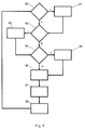
- Fig. 4 shows a flow chart for determining the suitable for a wear-optimized operation of the tillage machine parameters.
- a first query 80 it is determined whether the material properties 61 of the substrate to be removed are unknown, or whether changes in the material properties 61 may have resulted or have resulted in comparison to the previous determination of the optimum operating parameters. If a detection of the material properties 61 is necessary, this takes place in the first block 81. In this case, the material properties 61 can be entered, for example, by the operator, determined from a stored map or determined by the soil cultivation machine.
- the second query 82 determines whether default machine parameters 62.1 62.2, 62.3, 62.4 are to be taken into account. If this is the case, the default machine parameters 62.1 62.2, 62.3, 62.4 can be entered in the second block 83, for example by the machine operator, or determined from the machine parameters 18.1, 18.2, 18.3, 18.4 currently set in the control unit 19 of the soil tillage implement.
- third query 84 it is determined whether additional job parameters 63 are to be taken into account for the planned work operation of the tillage machine. These may then be entered by the operator in the third block 85.
- the default data record 60 is created in the fourth block 86. This takes into account the at least one material property 61 and optionally the present default machine parameters 62.1 62.2, 62.3, 62.4 and / or the job parameters 63.
- the default data record 60 is compared with the characteristic fields 64 stored in the memory unit 51, and the wear-optimized desired machine parameters 71.1, 71.2, 71.3, 71.4 are determined therefrom.
- the output of the desired machine parameters 71.1, 71.2, 71.3, 71.4 takes place. These can be displayed to the operator on the display unit 17 either directly or the operator can be given recommendations for changing machine parameters, for example a reduction in the feed rate or an increase in the rotational speed of the milling drum 15. Alternatively, the desired machine parameters 71.1, 71.2, 71.3 , 71.4 also be transmitted to the control unit 19 and, preferably after confirmation by the operator, be set directly.
- the previous steps, starting with the first query 80, can be run through again. This is particularly useful if the material properties 61 can change during the processing of the substrate.
- changes made manually by the operator to machine parameters 18.1, 18.2, 18.3, 18.4 as new default machine parameters 62.1 62.2, 62.3, 62.4 can be taken over into the default data record 60 and taken into account in the determination of the wear-optimized desired machine parameters 71.1, 71.2, 71.3, 71.4 become.
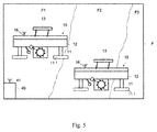
- Fig. 5 illustrates a milling area F, for example a mine, in which several milling machines 10 work.
- the milling area F includes a raw material deposit, wherein the material properties 61 change in subareas F1, F2, F3.
- An external system unit 40 is shown symbolically at the edge of the milling area F. It is connected via a transmitting and receiving device 41 wirelessly in connection with the milling machines 10.
- the system unit 40 is the in Fig. 3 Processing device 50 shown associated with the arithmetic unit 52 and the memory unit 51.
- the sub-areas F1, F2, F3 are assigned in mining maps hardness and abrasion categories as material parameters. These mine cards are stored in the storage unit 51 of the processing device 50. On the basis of the hardness and abrasion categories, the processing device 50 determines the suitable target machine parameters 71.1, 71.2, 71.3, 71.4 for the subareas F1, F2, F3 and sends them to the milling machines 10. In so doing, it takes into account predetermined job parameters 63 and default machine parameters 62.1 62.2, 62.3, 62.4. These can be sent, for example, from the milling machines 10 to the system unit 40 by means of second transmitting and receiving devices 16 provided thereon, or transmitted to the system unit 40 directly or from a further input device.
- the milling machines 10 can thus be operated in the different subareas F1, F2, F3 with different current machine parameters 18.1, 18.2, 18.3, 18.4, so that in each case the most favorable or the desired wear behavior of the tillage tools is present.
- the material properties 61 of the various subareas F1, F2, F3 can be determined, for example, by a preceding milling machine 10. As described above, this can be done on the basis of the present actual machine parameters 18.1, 18.2, 18.3, 18.4.
- the material properties 61 are then sent to the system unit 40, whereupon the computer unit 52 determines the optimized setpoint machine parameters 71.1, 71.2, 71.3, 71.4. These can then be transmitted spatially resolved to the two milling machines 10.
- the milling machines 10 may also be in direct radio contact with each other, so that the system unit 40 can be dispensed with.
- the desired machine parameters 71.1, 71.2, 71.3, 71.4 are then preferably determined by a milling machine 10 and sent to the second milling machine 10. It is possible to determine desired machine parameters 71.1, 71.2, 71.3, 71.4 adapted to the different subareas F1, F2, F3 or uniform setpoint machine parameters 71.1, 71.2, 71.3, 71.4 for the entire milling area F can be determined.
- the processing device 50 may be arranged on the milling machine 10.
- a mine card is processed electronically in the storage unit 51 and thus deposited.
- the milling machine 10 has a position detection system (for example GPS system) and additionally determines the desired machine parameters 71.1, 71.2, 71.3, 71.4 as a function of the current position and the stored mine data.
Landscapes
- Engineering & Computer Science (AREA)
- Mining & Mineral Resources (AREA)
- Mechanical Engineering (AREA)
- Life Sciences & Earth Sciences (AREA)
- General Life Sciences & Earth Sciences (AREA)
- Geochemistry & Mineralogy (AREA)
- Geology (AREA)
- Physics & Mathematics (AREA)
- General Physics & Mathematics (AREA)
- Automation & Control Theory (AREA)
- Architecture (AREA)
- Civil Engineering (AREA)
- Structural Engineering (AREA)
- Radar, Positioning & Navigation (AREA)
- Remote Sensing (AREA)
- Aviation & Aerospace Engineering (AREA)
- Numerical Control (AREA)
- Lifting Devices For Agricultural Implements (AREA)
- Management, Administration, Business Operations System, And Electronic Commerce (AREA)
- Soil Working Implements (AREA)
Priority Applications (2)
| Application Number | Priority Date | Filing Date | Title |
|---|---|---|---|
| EP23198969.0A EP4290010A3 (fr) | 2015-07-10 | 2016-06-21 | Machine de traitement du sol et procédé de fonctionnement optimisé en terme d'usure d'une machine de traitement du sol |
| EP20152400.6A EP3670748B1 (fr) | 2015-07-10 | 2016-06-21 | Machine de traitement du sol et procédé de fonctionnement optimisé en terme d'usure d'une machine de traitement du sol |
Applications Claiming Priority (1)
| Application Number | Priority Date | Filing Date | Title |
|---|---|---|---|
| DE102015111249.3A DE102015111249A1 (de) | 2015-07-10 | 2015-07-10 | Bodenbearbeitungsmaschine und Verfahren zum verschleißoptimierten Betrieb einer Bodenbearbeitungsmaschine |
Related Child Applications (3)
| Application Number | Title | Priority Date | Filing Date |
|---|---|---|---|
| EP23198969.0A Division EP4290010A3 (fr) | 2015-07-10 | 2016-06-21 | Machine de traitement du sol et procédé de fonctionnement optimisé en terme d'usure d'une machine de traitement du sol |
| EP20152400.6A Division EP3670748B1 (fr) | 2015-07-10 | 2016-06-21 | Machine de traitement du sol et procédé de fonctionnement optimisé en terme d'usure d'une machine de traitement du sol |
| EP20152400.6A Division-Into EP3670748B1 (fr) | 2015-07-10 | 2016-06-21 | Machine de traitement du sol et procédé de fonctionnement optimisé en terme d'usure d'une machine de traitement du sol |
Publications (2)
| Publication Number | Publication Date |
|---|---|
| EP3115507A1 true EP3115507A1 (fr) | 2017-01-11 |
| EP3115507B1 EP3115507B1 (fr) | 2020-03-11 |
Family
ID=56194318
Family Applications (3)
| Application Number | Title | Priority Date | Filing Date |
|---|---|---|---|
| EP23198969.0A Pending EP4290010A3 (fr) | 2015-07-10 | 2016-06-21 | Machine de traitement du sol et procédé de fonctionnement optimisé en terme d'usure d'une machine de traitement du sol |
| EP20152400.6A Active EP3670748B1 (fr) | 2015-07-10 | 2016-06-21 | Machine de traitement du sol et procédé de fonctionnement optimisé en terme d'usure d'une machine de traitement du sol |
| EP16175421.3A Active EP3115507B1 (fr) | 2015-07-10 | 2016-06-21 | Machine de travail du sol et procede de fonctionnement optimise contre l'usure d'une machine de travail du sol |
Family Applications Before (2)
| Application Number | Title | Priority Date | Filing Date |
|---|---|---|---|
| EP23198969.0A Pending EP4290010A3 (fr) | 2015-07-10 | 2016-06-21 | Machine de traitement du sol et procédé de fonctionnement optimisé en terme d'usure d'une machine de traitement du sol |
| EP20152400.6A Active EP3670748B1 (fr) | 2015-07-10 | 2016-06-21 | Machine de traitement du sol et procédé de fonctionnement optimisé en terme d'usure d'une machine de traitement du sol |
Country Status (4)
| Country | Link |
|---|---|
| US (3) | US10287882B2 (fr) |
| EP (3) | EP4290010A3 (fr) |
| CN (3) | CN106337355A (fr) |
| DE (1) | DE102015111249A1 (fr) |
Cited By (5)
| Publication number | Priority date | Publication date | Assignee | Title |
|---|---|---|---|---|
| EP3205773A1 (fr) * | 2016-02-15 | 2017-08-16 | Wirtgen GmbH | Procédé de planification pour des travaux de fraisage de routes et programme informatique associé |
| US10323516B2 (en) | 2016-11-11 | 2019-06-18 | Wirtgen Gmbh | System and method for the tracking of milling material |
| US10329910B2 (en) | 2016-11-25 | 2019-06-25 | Wirtgen Gmbh | System and method for the tracking of milling material |
| EP3501744A1 (fr) * | 2017-12-20 | 2019-06-26 | Wirtgen GmbH | Outil pour le montage d'un ciseau à et / ou le démontage d'un ciseau d'un système de porte-ciseau d'une fraiseuse |
| US10927513B2 (en) | 2016-11-11 | 2021-02-23 | Wirtgen Gmbh | System and method for the tracking of milling material |
Families Citing this family (17)
| Publication number | Priority date | Publication date | Assignee | Title |
|---|---|---|---|---|
| DE102015111249A1 (de) * | 2015-07-10 | 2017-01-12 | Wirtgen Gmbh | Bodenbearbeitungsmaschine und Verfahren zum verschleißoptimierten Betrieb einer Bodenbearbeitungsmaschine |
| DE102016113251A1 (de) | 2015-10-27 | 2017-04-27 | Wirtgen Gmbh | Fräsmaschine und Verfahren zum Betrieb einer Fräsmaschine |
| US10385688B2 (en) * | 2016-12-21 | 2019-08-20 | Caterpillar Paving Products Inc. | Wear monitoring system for milling drum |
| US11208771B2 (en) | 2019-11-20 | 2021-12-28 | Caterpillar Paving Products Inc. | System and method for controlling plunge velocity for milling and reclaiming machines |
| US11555403B2 (en) | 2020-03-13 | 2023-01-17 | Joy Global Underground Mining Llc | Cutting pick monitoring system and method for longwall mining system |
| US11732426B2 (en) * | 2020-12-11 | 2023-08-22 | Caterpillar Paving Products Inc. | Systems and methods for counting work machine bit removal |
| US11661846B2 (en) | 2021-02-01 | 2023-05-30 | Caterpillar Paving Products Inc. | Systems and methods for replacing wear parts |
| DE102021117493A1 (de) | 2021-07-07 | 2023-01-12 | Wirtgen Gmbh | Verfahren zum Betrieb einer Bodenfräsmaschine |
| DE102021133306A1 (de) | 2021-12-15 | 2023-06-15 | Wirtgen Gmbh | Verfahren zur Aufwands-Abschätzung einer geplanten Fräsaufgabe, die mit einer Straßenfräsmaschine durchgeführt wird oder durchgeführt werden soll |
| US20230196851A1 (en) * | 2021-12-22 | 2023-06-22 | Cnh Industrial Canada, Ltd. | Agricultural system and method for monitoring wear rates of agricultural implements |
| CN114993635B (zh) * | 2022-04-18 | 2023-04-18 | 湖南三一中益机械有限公司 | 铣刨刀具检测方法、检测系统、电子设备和铣刨机 |
| US12351995B2 (en) | 2022-04-28 | 2025-07-08 | Caterpillar Paving Products Inc. | Auto scratch height for work machines |
| DE102022114940A1 (de) | 2022-06-14 | 2023-12-14 | RockFeel GmbH | Verfahren und Abtragsystem |
| DE102022122472B4 (de) | 2022-09-05 | 2024-03-28 | Wirtgen Gmbh | Selbstfahrende Bodenbearbeitungsmaschine mit Zwillingsmotoren und einem deren Leistung unterschiedlich übertragenden Arbeitsgetriebe |
| US12540834B2 (en) | 2023-04-12 | 2026-02-03 | Deere & Company | Automated recognition and performance of vehicle to camera calibration |
| US12596384B2 (en) | 2024-03-05 | 2026-04-07 | Deere & Company | System and method for mapping obstructions in a work area to corresponding locations |
| DE102024111241A1 (de) | 2024-04-22 | 2025-10-23 | Benninghoven Zweigniederlassung Der Wirtgen Mineral Technologies Gmbh | Verfahren zur einzelprozessübergreifenden Optimierung eines multiprozessualen Verarbeitungsvorgangs unter Beteiligung eines Recyclings von mineralischem Verarbeitungsmaterial |
Citations (4)
| Publication number | Priority date | Publication date | Assignee | Title |
|---|---|---|---|---|
| DE10213017A1 (de) * | 2002-03-22 | 2003-10-09 | Wirtgen Gmbh | Verfahren zum Optimieren eines Schneidprozesses bei Straßenfräsmaschinen, sowie Fräsmaschine zum Bearbeiten von Straßendecken |
| US20040120766A1 (en) * | 2002-12-24 | 2004-06-24 | Silay Louis E. | Closed loop control system for pavement surfacing machine |
| DE102008045470A1 (de) | 2008-09-03 | 2010-03-04 | Wirtgen Gmbh | Verfahren zur Bestimmung des Verschleißzustandes |
| DE102014015661A1 (de) | 2013-10-25 | 2015-04-30 | Caterpillar Paving Products Inc. | Fräsmaschinensteuerung gemäss bodencharakteristik |
Family Cites Families (30)
| Publication number | Priority date | Publication date | Assignee | Title |
|---|---|---|---|---|
| US4006936A (en) | 1975-11-06 | 1977-02-08 | Dresser Industries, Inc. | Rotary cutter for a road planer |
| DE3218754C2 (de) | 1982-05-18 | 1985-11-28 | Friedrich Deckel AG, 8000 München | Verfahren und Einrichtung zur Vermessung eines in einem zustellbaren Werkzeughalter einer Werkzeugmaschine eingespannten Werkzeugs |
| DE3411892C2 (de) | 1984-03-30 | 1986-06-19 | Oerlikon-Boehringer GmbH, 7320 Göppingen | Vorrichtung zum Messen des Verschleißes der Werkzeuge einer Fräsmaschine |
| DE3505408A1 (de) | 1985-02-16 | 1986-08-21 | Gebr. Eickhoff Maschinenfabrik U. Eisengiesserei Mbh, 4630 Bochum | Verfahren zum feststellen des verschleisses von schraemmeisseln einer schraemwalze |
| AT382683B (de) | 1985-08-16 | 1987-03-25 | Voest Alpine Ag | Einrichtung zur ueberwachung des abnuetzungsgrades von meisseln eines schraemkopfes |
| US4655634A (en) | 1985-09-23 | 1987-04-07 | Dresser Industries, Inc. | Road planer control and safety system |
| DE3818213A1 (de) | 1988-05-28 | 1989-11-30 | Gewerk Eisenhuette Westfalia | Meissel, insbesondere fuer bergbau-gewinnungsmaschinen, vortriebsmaschinen u. dgl. |
| JP3184432B2 (ja) | 1995-07-28 | 2001-07-09 | 株式会社奥村組 | ローラビットの摩耗検知装置 |
| JPH09168944A (ja) | 1995-12-20 | 1997-06-30 | Komatsu Ltd | ターンブローチの異常検出装置 |
| US6149342A (en) | 1999-03-25 | 2000-11-21 | Cmi Corporation | Anti-bridging mechanism |
| DE10015005A1 (de) | 2000-03-20 | 2001-10-18 | Georg Wendland | Einrichtung zur Online-Messung des Werkzeugverschleisses beim Spanen von abrasiven Materialien |
| JP2002082033A (ja) * | 2000-06-30 | 2002-03-22 | Abe Yorimasa | 荷重移動試験装置及び荷重移動試験方法 |
| DE10203732A1 (de) | 2002-01-30 | 2003-08-21 | Wirtgen Gmbh | Baumaschine |
| DE10241067B3 (de) | 2002-09-05 | 2004-04-22 | Wirtgen Gmbh | Vorrichtung zum Bearbeiten von Böden oder Fahrbahnen |
| US6990390B2 (en) | 2004-05-19 | 2006-01-24 | Caterpillar Inc. | Method and apparatus to detect change in work tool |
| DE102005016346B3 (de) | 2005-04-09 | 2007-01-04 | Hochtief Construction Ag | Diskenmeißel-Verschleißmessvorrichtung und Verfahren zur Messung eines Diskenmeißelverschleißes |
| US7731450B2 (en) * | 2006-09-07 | 2010-06-08 | Caterpillar Inc. | Method of operating a compactor machine via path planning based on compaction state data and mapping information |
| US20080153402A1 (en) | 2006-12-20 | 2008-06-26 | Christopher Arcona | Roadway grinding/cutting apparatus and monitoring system |
| DE102007007970B4 (de) | 2007-02-17 | 2009-11-26 | Wirtgen Gmbh | Baumaschine, insbesondere Straßenbaumaschine |
| CN201155077Y (zh) * | 2008-01-31 | 2008-11-26 | 吴骏 | 用于路面摊铺机的数字找平仪 |
| CN201181417Y (zh) * | 2008-02-29 | 2009-01-14 | 陈军 | 用于摊铺机或铣刨机的工业控制器 |
| US8794867B2 (en) | 2011-05-26 | 2014-08-05 | Trimble Navigation Limited | Asphalt milling machine control and method |
| US8738304B2 (en) | 2011-08-02 | 2014-05-27 | David R. Hall | System for acquiring data from a component |
| US8608250B2 (en) * | 2011-09-30 | 2013-12-17 | Joy Mm Delaware, Inc. | Slow turning drum for a miner |
| US9022140B2 (en) | 2012-10-31 | 2015-05-05 | Resource Energy Solutions Inc. | Methods and systems for improved drilling operations using real-time and historical drilling data |
| DE102013112972A1 (de) | 2013-11-25 | 2015-05-28 | Wirtgen Gmbh | Verschleißprognoseverfahren und Wartungsverfahren |
| CN204212037U (zh) * | 2014-10-31 | 2015-03-18 | 徐州徐工筑路机械有限公司 | 铣刨机边板及刮板的电控系统 |
| US20160258119A1 (en) * | 2015-03-03 | 2016-09-08 | Caterpillar Inc. | Automatic Rotor Speed Control |
| AU2016202171A1 (en) * | 2015-04-09 | 2016-10-27 | Joy Global Underground Mining Llc | System and method of detecting dull and worn cutter bits |
| DE102015111249A1 (de) * | 2015-07-10 | 2017-01-12 | Wirtgen Gmbh | Bodenbearbeitungsmaschine und Verfahren zum verschleißoptimierten Betrieb einer Bodenbearbeitungsmaschine |
-
2015
- 2015-07-10 DE DE102015111249.3A patent/DE102015111249A1/de active Pending
-
2016
- 2016-06-21 EP EP23198969.0A patent/EP4290010A3/fr active Pending
- 2016-06-21 EP EP20152400.6A patent/EP3670748B1/fr active Active
- 2016-06-21 EP EP16175421.3A patent/EP3115507B1/fr active Active
- 2016-06-29 US US15/196,317 patent/US10287882B2/en active Active
- 2016-07-08 CN CN201610537714.5A patent/CN106337355A/zh active Pending
- 2016-07-08 CN CN201620719704.9U patent/CN206279431U/zh active Active
- 2016-07-08 CN CN202110692018.2A patent/CN113373779A/zh active Pending
-
2019
- 2019-05-09 US US16/407,556 patent/US11401808B2/en active Active
-
2022
- 2022-07-12 US US17/862,565 patent/US12398641B2/en active Active
Patent Citations (4)
| Publication number | Priority date | Publication date | Assignee | Title |
|---|---|---|---|---|
| DE10213017A1 (de) * | 2002-03-22 | 2003-10-09 | Wirtgen Gmbh | Verfahren zum Optimieren eines Schneidprozesses bei Straßenfräsmaschinen, sowie Fräsmaschine zum Bearbeiten von Straßendecken |
| US20040120766A1 (en) * | 2002-12-24 | 2004-06-24 | Silay Louis E. | Closed loop control system for pavement surfacing machine |
| DE102008045470A1 (de) | 2008-09-03 | 2010-03-04 | Wirtgen Gmbh | Verfahren zur Bestimmung des Verschleißzustandes |
| DE102014015661A1 (de) | 2013-10-25 | 2015-04-30 | Caterpillar Paving Products Inc. | Fräsmaschinensteuerung gemäss bodencharakteristik |
Cited By (10)
| Publication number | Priority date | Publication date | Assignee | Title |
|---|---|---|---|---|
| EP3205773A1 (fr) * | 2016-02-15 | 2017-08-16 | Wirtgen GmbH | Procédé de planification pour des travaux de fraisage de routes et programme informatique associé |
| US10156046B2 (en) | 2016-02-15 | 2018-12-18 | Wirtgen Gmbh | Planning system and method for coordinating road milling tasks |
| US10794010B2 (en) | 2016-02-15 | 2020-10-06 | Wirtgen Gmbh | Planning system and method for coordinating road milling tasks |
| US11346062B2 (en) | 2016-02-15 | 2022-05-31 | Wirtgen Gmbh | Planning system and method for coordinating road milling tasks |
| US10323516B2 (en) | 2016-11-11 | 2019-06-18 | Wirtgen Gmbh | System and method for the tracking of milling material |
| US10927513B2 (en) | 2016-11-11 | 2021-02-23 | Wirtgen Gmbh | System and method for the tracking of milling material |
| US10329910B2 (en) | 2016-11-25 | 2019-06-25 | Wirtgen Gmbh | System and method for the tracking of milling material |
| EP3501744A1 (fr) * | 2017-12-20 | 2019-06-26 | Wirtgen GmbH | Outil pour le montage d'un ciseau à et / ou le démontage d'un ciseau d'un système de porte-ciseau d'une fraiseuse |
| CN109944145A (zh) * | 2017-12-20 | 2019-06-28 | 维特根有限公司 | 用于将凿刀在凿刀支架系统上安装和/或拆卸的工具 |
| CN109944145B (zh) * | 2017-12-20 | 2021-06-25 | 维特根有限公司 | 用于将凿刀在凿刀支架系统上安装和/或拆卸的工具 |
Also Published As
| Publication number | Publication date |
|---|---|
| DE102015111249A1 (de) | 2017-01-12 |
| US12398641B2 (en) | 2025-08-26 |
| EP3670748A1 (fr) | 2020-06-24 |
| EP4290010A3 (fr) | 2024-02-28 |
| US20170009578A1 (en) | 2017-01-12 |
| US20190360333A1 (en) | 2019-11-28 |
| EP3670748C0 (fr) | 2023-12-06 |
| EP4290010A2 (fr) | 2023-12-13 |
| EP3115507B1 (fr) | 2020-03-11 |
| CN106337355A (zh) | 2017-01-18 |
| US10287882B2 (en) | 2019-05-14 |
| US20230105339A1 (en) | 2023-04-06 |
| CN113373779A (zh) | 2021-09-10 |
| US11401808B2 (en) | 2022-08-02 |
| EP3670748B1 (fr) | 2023-12-06 |
| CN206279431U (zh) | 2017-06-27 |
Similar Documents
| Publication | Publication Date | Title |
|---|---|---|
| EP3670748B1 (fr) | Machine de traitement du sol et procédé de fonctionnement optimisé en terme d'usure d'une machine de traitement du sol | |
| EP2887049B1 (fr) | Procédé de pronostic d'usure pour une machine de travail de sols | |
| EP3205773B1 (fr) | Système de commande pour l'opération de fraiseuses routières | |
| EP2514871B1 (fr) | Procédé pour la pose et le compactage d'une couche d'asphalte | |
| DE102020117095A1 (de) | Automatische breiteneingabe für strassenfertigungsvorgänge | |
| DE102018128923A1 (de) | Automatische Steuerung der Eintauchgeschwindigkeit auf Basis der Frästiefe | |
| DE102016113251A1 (de) | Fräsmaschine und Verfahren zum Betrieb einer Fräsmaschine | |
| EP3456167A1 (fr) | Engin agricole | |
| DE102016006351A1 (de) | Kaltfräse mit einem Transportnutzlastüberwachungssystem | |
| DE102016002700A1 (de) | Steuersystem mit Hindernisdetektion und Aufzeichnung | |
| DE102006053388A1 (de) | Arbeitsmaschine mit einem Übergangsregionsteuersystem | |
| EP3290586A1 (fr) | Fraiseuse et procédé de fonctionnement d'une fraiseuse | |
| DE102014001885A1 (de) | Verfahren zur Optimierung einer Betriebsfunktion einer Bodenfräsmaschine und Bodenfräsmaschine | |
| DE112016004648T5 (de) | Lastkraftwagenpositionskontrollsystem für fräsvorgänge | |
| EP3162959B1 (fr) | Fraiseuse et procede de fonctionnement d'une fraiseuse | |
| EP2696173A1 (fr) | Engin avec unité de détection | |
| DE112015003533T5 (de) | Kaltfräse mit unabhängig gesteuerten Fördereinrichtungen | |
| DE102016009201A1 (de) | Systeme und verfahren zur überwachung einer abbauhöhe und eines volumens eines gewonnenen materials für eine abbaumaschine | |
| DE102013112973A1 (de) | Verschleißprognoseverfahren und Wartungsverfahren | |
| EP3208382B1 (fr) | Engin automobile et procédé de fonctionnement d'un engin automobile | |
| DE102015017137A1 (de) | Bodenbearbeitungsmaschine und Verfahren zum verschleißoptimierten Betrieb einer Bodenbearbeitungsmaschine | |
| EP4116494B1 (fr) | Procédé permettant de faire fonctionner une machine à fraiser le sol | |
| DE20010498U1 (de) | Straßenfertiger | |
| EP2982796A1 (fr) | Finisseuse de route et procédé d'opération d'une finisseuse de route | |
| EP4198850A1 (fr) | Procédé d'estimation de la paroi d'une tâche de fraisage planifiée effectuée ou devant être effectuée à l'aide d'une fraiseuse routière |
Legal Events
| Date | Code | Title | Description |
|---|---|---|---|
| PUAI | Public reference made under article 153(3) epc to a published international application that has entered the european phase |
Free format text: ORIGINAL CODE: 0009012 |
|
| STAA | Information on the status of an ep patent application or granted ep patent |
Free format text: STATUS: THE APPLICATION HAS BEEN PUBLISHED |
|
| AK | Designated contracting states |
Kind code of ref document: A1 Designated state(s): AL AT BE BG CH CY CZ DE DK EE ES FI FR GB GR HR HU IE IS IT LI LT LU LV MC MK MT NL NO PL PT RO RS SE SI SK SM TR |
|
| AX | Request for extension of the european patent |
Extension state: BA ME |
|
| STAA | Information on the status of an ep patent application or granted ep patent |
Free format text: STATUS: REQUEST FOR EXAMINATION WAS MADE |
|
| 17P | Request for examination filed |
Effective date: 20170711 |
|
| RBV | Designated contracting states (corrected) |
Designated state(s): AL AT BE BG CH CY CZ DE DK EE ES FI FR GB GR HR HU IE IS IT LI LT LU LV MC MK MT NL NO PL PT RO RS SE SI SK SM TR |
|
| STAA | Information on the status of an ep patent application or granted ep patent |
Free format text: STATUS: EXAMINATION IS IN PROGRESS |
|
| 17Q | First examination report despatched |
Effective date: 20180425 |
|
| GRAP | Despatch of communication of intention to grant a patent |
Free format text: ORIGINAL CODE: EPIDOSNIGR1 |
|
| STAA | Information on the status of an ep patent application or granted ep patent |
Free format text: STATUS: GRANT OF PATENT IS INTENDED |
|
| INTG | Intention to grant announced |
Effective date: 20191217 |
|
| GRAS | Grant fee paid |
Free format text: ORIGINAL CODE: EPIDOSNIGR3 |
|
| GRAA | (expected) grant |
Free format text: ORIGINAL CODE: 0009210 |
|
| STAA | Information on the status of an ep patent application or granted ep patent |
Free format text: STATUS: THE PATENT HAS BEEN GRANTED |
|
| AK | Designated contracting states |
Kind code of ref document: B1 Designated state(s): AL AT BE BG CH CY CZ DE DK EE ES FI FR GB GR HR HU IE IS IT LI LT LU LV MC MK MT NL NO PL PT RO RS SE SI SK SM TR |
|
| REG | Reference to a national code |
Ref country code: GB Ref legal event code: FG4D Free format text: NOT ENGLISH |
|
| REG | Reference to a national code |
Ref country code: CH Ref legal event code: EP |
|
| REG | Reference to a national code |
Ref country code: AT Ref legal event code: REF Ref document number: 1243276 Country of ref document: AT Kind code of ref document: T Effective date: 20200315 |
|
| REG | Reference to a national code |
Ref country code: IE Ref legal event code: FG4D Free format text: LANGUAGE OF EP DOCUMENT: GERMAN |
|
| REG | Reference to a national code |
Ref country code: DE Ref legal event code: R096 Ref document number: 502016009090 Country of ref document: DE |
|
| REG | Reference to a national code |
Ref country code: SE Ref legal event code: TRGR |
|
| PG25 | Lapsed in a contracting state [announced via postgrant information from national office to epo] |
Ref country code: FI Free format text: LAPSE BECAUSE OF FAILURE TO SUBMIT A TRANSLATION OF THE DESCRIPTION OR TO PAY THE FEE WITHIN THE PRESCRIBED TIME-LIMIT Effective date: 20200311 Ref country code: RS Free format text: LAPSE BECAUSE OF FAILURE TO SUBMIT A TRANSLATION OF THE DESCRIPTION OR TO PAY THE FEE WITHIN THE PRESCRIBED TIME-LIMIT Effective date: 20200311 Ref country code: NO Free format text: LAPSE BECAUSE OF FAILURE TO SUBMIT A TRANSLATION OF THE DESCRIPTION OR TO PAY THE FEE WITHIN THE PRESCRIBED TIME-LIMIT Effective date: 20200611 |
|
| REG | Reference to a national code |
Ref country code: NL Ref legal event code: MP Effective date: 20200311 |
|
| PG25 | Lapsed in a contracting state [announced via postgrant information from national office to epo] |
Ref country code: GR Free format text: LAPSE BECAUSE OF FAILURE TO SUBMIT A TRANSLATION OF THE DESCRIPTION OR TO PAY THE FEE WITHIN THE PRESCRIBED TIME-LIMIT Effective date: 20200612 Ref country code: BG Free format text: LAPSE BECAUSE OF FAILURE TO SUBMIT A TRANSLATION OF THE DESCRIPTION OR TO PAY THE FEE WITHIN THE PRESCRIBED TIME-LIMIT Effective date: 20200611 Ref country code: HR Free format text: LAPSE BECAUSE OF FAILURE TO SUBMIT A TRANSLATION OF THE DESCRIPTION OR TO PAY THE FEE WITHIN THE PRESCRIBED TIME-LIMIT Effective date: 20200311 Ref country code: LV Free format text: LAPSE BECAUSE OF FAILURE TO SUBMIT A TRANSLATION OF THE DESCRIPTION OR TO PAY THE FEE WITHIN THE PRESCRIBED TIME-LIMIT Effective date: 20200311 |
|
| REG | Reference to a national code |
Ref country code: LT Ref legal event code: MG4D |
|
| PG25 | Lapsed in a contracting state [announced via postgrant information from national office to epo] |
Ref country code: NL Free format text: LAPSE BECAUSE OF FAILURE TO SUBMIT A TRANSLATION OF THE DESCRIPTION OR TO PAY THE FEE WITHIN THE PRESCRIBED TIME-LIMIT Effective date: 20200311 |
|
| PG25 | Lapsed in a contracting state [announced via postgrant information from national office to epo] |
Ref country code: PT Free format text: LAPSE BECAUSE OF FAILURE TO SUBMIT A TRANSLATION OF THE DESCRIPTION OR TO PAY THE FEE WITHIN THE PRESCRIBED TIME-LIMIT Effective date: 20200805 Ref country code: CZ Free format text: LAPSE BECAUSE OF FAILURE TO SUBMIT A TRANSLATION OF THE DESCRIPTION OR TO PAY THE FEE WITHIN THE PRESCRIBED TIME-LIMIT Effective date: 20200311 Ref country code: IS Free format text: LAPSE BECAUSE OF FAILURE TO SUBMIT A TRANSLATION OF THE DESCRIPTION OR TO PAY THE FEE WITHIN THE PRESCRIBED TIME-LIMIT Effective date: 20200711 Ref country code: SM Free format text: LAPSE BECAUSE OF FAILURE TO SUBMIT A TRANSLATION OF THE DESCRIPTION OR TO PAY THE FEE WITHIN THE PRESCRIBED TIME-LIMIT Effective date: 20200311 Ref country code: LT Free format text: LAPSE BECAUSE OF FAILURE TO SUBMIT A TRANSLATION OF THE DESCRIPTION OR TO PAY THE FEE WITHIN THE PRESCRIBED TIME-LIMIT Effective date: 20200311 Ref country code: SK Free format text: LAPSE BECAUSE OF FAILURE TO SUBMIT A TRANSLATION OF THE DESCRIPTION OR TO PAY THE FEE WITHIN THE PRESCRIBED TIME-LIMIT Effective date: 20200311 Ref country code: RO Free format text: LAPSE BECAUSE OF FAILURE TO SUBMIT A TRANSLATION OF THE DESCRIPTION OR TO PAY THE FEE WITHIN THE PRESCRIBED TIME-LIMIT Effective date: 20200311 Ref country code: EE Free format text: LAPSE BECAUSE OF FAILURE TO SUBMIT A TRANSLATION OF THE DESCRIPTION OR TO PAY THE FEE WITHIN THE PRESCRIBED TIME-LIMIT Effective date: 20200311 |
|
| REG | Reference to a national code |
Ref country code: DE Ref legal event code: R097 Ref document number: 502016009090 Country of ref document: DE |
|
| PLBE | No opposition filed within time limit |
Free format text: ORIGINAL CODE: 0009261 |
|
| STAA | Information on the status of an ep patent application or granted ep patent |
Free format text: STATUS: NO OPPOSITION FILED WITHIN TIME LIMIT |
|
| PG25 | Lapsed in a contracting state [announced via postgrant information from national office to epo] |
Ref country code: MC Free format text: LAPSE BECAUSE OF FAILURE TO SUBMIT A TRANSLATION OF THE DESCRIPTION OR TO PAY THE FEE WITHIN THE PRESCRIBED TIME-LIMIT Effective date: 20200311 Ref country code: ES Free format text: LAPSE BECAUSE OF FAILURE TO SUBMIT A TRANSLATION OF THE DESCRIPTION OR TO PAY THE FEE WITHIN THE PRESCRIBED TIME-LIMIT Effective date: 20200311 Ref country code: DK Free format text: LAPSE BECAUSE OF FAILURE TO SUBMIT A TRANSLATION OF THE DESCRIPTION OR TO PAY THE FEE WITHIN THE PRESCRIBED TIME-LIMIT Effective date: 20200311 |
|
| REG | Reference to a national code |
Ref country code: CH Ref legal event code: PL |
|
| 26N | No opposition filed |
Effective date: 20201214 |
|
| PG25 | Lapsed in a contracting state [announced via postgrant information from national office to epo] |
Ref country code: PL Free format text: LAPSE BECAUSE OF FAILURE TO SUBMIT A TRANSLATION OF THE DESCRIPTION OR TO PAY THE FEE WITHIN THE PRESCRIBED TIME-LIMIT Effective date: 20200311 Ref country code: SI Free format text: LAPSE BECAUSE OF FAILURE TO SUBMIT A TRANSLATION OF THE DESCRIPTION OR TO PAY THE FEE WITHIN THE PRESCRIBED TIME-LIMIT Effective date: 20200311 |
|
| PG25 | Lapsed in a contracting state [announced via postgrant information from national office to epo] |
Ref country code: LU Free format text: LAPSE BECAUSE OF NON-PAYMENT OF DUE FEES Effective date: 20200621 |
|
| REG | Reference to a national code |
Ref country code: BE Ref legal event code: MM Effective date: 20200630 |
|
| PG25 | Lapsed in a contracting state [announced via postgrant information from national office to epo] |
Ref country code: IE Free format text: LAPSE BECAUSE OF NON-PAYMENT OF DUE FEES Effective date: 20200621 Ref country code: LI Free format text: LAPSE BECAUSE OF NON-PAYMENT OF DUE FEES Effective date: 20200630 Ref country code: CH Free format text: LAPSE BECAUSE OF NON-PAYMENT OF DUE FEES Effective date: 20200630 |
|
| PG25 | Lapsed in a contracting state [announced via postgrant information from national office to epo] |
Ref country code: BE Free format text: LAPSE BECAUSE OF NON-PAYMENT OF DUE FEES Effective date: 20200630 |
|
| PG25 | Lapsed in a contracting state [announced via postgrant information from national office to epo] |
Ref country code: TR Free format text: LAPSE BECAUSE OF FAILURE TO SUBMIT A TRANSLATION OF THE DESCRIPTION OR TO PAY THE FEE WITHIN THE PRESCRIBED TIME-LIMIT Effective date: 20200311 Ref country code: MT Free format text: LAPSE BECAUSE OF FAILURE TO SUBMIT A TRANSLATION OF THE DESCRIPTION OR TO PAY THE FEE WITHIN THE PRESCRIBED TIME-LIMIT Effective date: 20200311 Ref country code: CY Free format text: LAPSE BECAUSE OF FAILURE TO SUBMIT A TRANSLATION OF THE DESCRIPTION OR TO PAY THE FEE WITHIN THE PRESCRIBED TIME-LIMIT Effective date: 20200311 |
|
| PG25 | Lapsed in a contracting state [announced via postgrant information from national office to epo] |
Ref country code: MK Free format text: LAPSE BECAUSE OF FAILURE TO SUBMIT A TRANSLATION OF THE DESCRIPTION OR TO PAY THE FEE WITHIN THE PRESCRIBED TIME-LIMIT Effective date: 20200311 Ref country code: AL Free format text: LAPSE BECAUSE OF FAILURE TO SUBMIT A TRANSLATION OF THE DESCRIPTION OR TO PAY THE FEE WITHIN THE PRESCRIBED TIME-LIMIT Effective date: 20200311 |
|
| REG | Reference to a national code |
Ref country code: AT Ref legal event code: MM01 Ref document number: 1243276 Country of ref document: AT Kind code of ref document: T Effective date: 20210621 |
|
| PG25 | Lapsed in a contracting state [announced via postgrant information from national office to epo] |
Ref country code: AT Free format text: LAPSE BECAUSE OF NON-PAYMENT OF DUE FEES Effective date: 20210621 |
|
| P01 | Opt-out of the competence of the unified patent court (upc) registered |
Effective date: 20230525 |
|
| PGFP | Annual fee paid to national office [announced via postgrant information from national office to epo] |
Ref country code: DE Payment date: 20250618 Year of fee payment: 10 |
|
| PGFP | Annual fee paid to national office [announced via postgrant information from national office to epo] |
Ref country code: GB Payment date: 20250620 Year of fee payment: 10 |
|
| PGFP | Annual fee paid to national office [announced via postgrant information from national office to epo] |
Ref country code: FR Payment date: 20250618 Year of fee payment: 10 |
|
| PGFP | Annual fee paid to national office [announced via postgrant information from national office to epo] |
Ref country code: SE Payment date: 20250618 Year of fee payment: 10 |
|
| PGFP | Annual fee paid to national office [announced via postgrant information from national office to epo] |
Ref country code: IT Payment date: 20250630 Year of fee payment: 10 |