EP3116067B1 - Dispositif de connexion comprenant une borne enfichable - Google Patents
Dispositif de connexion comprenant une borne enfichable Download PDFInfo
- Publication number
- EP3116067B1 EP3116067B1 EP16174157.4A EP16174157A EP3116067B1 EP 3116067 B1 EP3116067 B1 EP 3116067B1 EP 16174157 A EP16174157 A EP 16174157A EP 3116067 B1 EP3116067 B1 EP 3116067B1
- Authority
- EP
- European Patent Office
- Prior art keywords
- clamping
- contact
- latching
- spring
- insulating profile
- Prior art date
- Legal status (The legal status is an assumption and is not a legal conclusion. Google has not performed a legal analysis and makes no representation as to the accuracy of the status listed.)
- Active
Links
Images


Classifications
-
- H—ELECTRICITY
- H01—ELECTRIC ELEMENTS
- H01R—ELECTRICALLY-CONDUCTIVE CONNECTIONS; STRUCTURAL ASSOCIATIONS OF A PLURALITY OF MUTUALLY-INSULATED ELECTRICAL CONNECTING ELEMENTS; COUPLING DEVICES; CURRENT COLLECTORS
- H01R9/00—Structural associations of a plurality of mutually-insulated electrical connecting elements, e.g. terminal strips or terminal blocks; Terminals or binding posts mounted upon a base or in a case; Bases therefor
- H01R9/22—Bases, e.g. strip, block, panel
- H01R9/24—Terminal blocks
- H01R9/2458—Electrical interconnections between terminal blocks
-
- H—ELECTRICITY
- H01—ELECTRIC ELEMENTS
- H01R—ELECTRICALLY-CONDUCTIVE CONNECTIONS; STRUCTURAL ASSOCIATIONS OF A PLURALITY OF MUTUALLY-INSULATED ELECTRICAL CONNECTING ELEMENTS; COUPLING DEVICES; CURRENT COLLECTORS
- H01R4/00—Electrically-conductive connections between two or more conductive members in direct contact, i.e. touching one another; Means for effecting or maintaining such contact; Electrically-conductive connections having two or more spaced connecting locations for conductors and using contact members penetrating insulation
- H01R4/28—Clamped connections, spring connections
- H01R4/48—Clamped connections, spring connections utilising a spring, clip, or other resilient member
- H01R4/4809—Clamped connections, spring connections utilising a spring, clip, or other resilient member using a leaf spring to bias the conductor toward the busbar
- H01R4/48185—Clamped connections, spring connections utilising a spring, clip, or other resilient member using a leaf spring to bias the conductor toward the busbar adapted for axial insertion of a wire end
- H01R4/4819—Clamped connections, spring connections utilising a spring, clip, or other resilient member using a leaf spring to bias the conductor toward the busbar adapted for axial insertion of a wire end the spring shape allowing insertion of the conductor end when the spring is unbiased
- H01R4/4821—Single-blade spring
-
- H—ELECTRICITY
- H01—ELECTRIC ELEMENTS
- H01R—ELECTRICALLY-CONDUCTIVE CONNECTIONS; STRUCTURAL ASSOCIATIONS OF A PLURALITY OF MUTUALLY-INSULATED ELECTRICAL CONNECTING ELEMENTS; COUPLING DEVICES; CURRENT COLLECTORS
- H01R4/00—Electrically-conductive connections between two or more conductive members in direct contact, i.e. touching one another; Means for effecting or maintaining such contact; Electrically-conductive connections having two or more spaced connecting locations for conductors and using contact members penetrating insulation
- H01R4/28—Clamped connections, spring connections
- H01R4/48—Clamped connections, spring connections utilising a spring, clip, or other resilient member
- H01R4/4809—Clamped connections, spring connections utilising a spring, clip, or other resilient member using a leaf spring to bias the conductor toward the busbar
- H01R4/4828—Spring-activating arrangements mounted on or integrally formed with the spring housing
- H01R4/483—Pivoting arrangements, e.g. lever pushing on the spring
Definitions
- the invention is based on a connecting device which has at least one installation switching device with a housing and with at least one screwless terminal and at least one connecting element, the connecting element having at least one connecting conductor with at least one contact lug arranged thereon, according to the preamble of claim 1.
- connection device is known in connection with circuit breakers, residual current circuit breakers, motor protection switches, relays or contactors, in particular for use in distributors or switchgear in industrial use, for example in the power supply or control of motors or in low-voltage switchgear.
- An example of a connecting element that can be used in a generic connecting device is a busbar.
- a busbar is a device for simultaneously electrically connecting a plurality of lined-up connections of one or more lined-up installation switching devices to one another.
- the pole rail of the busbar and the contact lugs which usually protrude from the pole rail in an approximately comb-like manner, are made of a rigid and electrically highly conductive material, for example a rigid guide plate, preferably made of copper or a highly conductive copper alloy.
- the pole rail is housed in an insulating profile from which the contact tabs protrude through openings at the designated locations.
- Plug connectors are used to establish an electrical connection between the connection terminals of, for example, a motor protection switch and a contactor.
- a connector for connecting two three-phase devices has, for example, three connecting conductors, which can be arranged together in an insulating housing, with two contact tabs protruding from each connecting conductor, one for insertion into the connection terminal of the motor protection switch and one for insertion into the connection terminal of the contactor.
- a connecting element that can be used in a generic connecting device for the electrical connection of a three-pole contactor is a so-called reversible connector.
- this is a three-pole connector in which the connecting conductors between the individual poles of the two devices to be connected are arranged in such a way that the running direction of a connected motor is reversed.
- screw terminals are used for installation switchgear used in industrial environments. Connecting a connecting element takes place in two steps. First, the connecting element is placed on the open screw terminals, and the contact lugs of the busbar are inserted into the open screw terminals. The clamping screws are then tightened one after the other.
- the spring-loaded terminal has a clamping frame and an approximately Q-shaped clamping spring, which has a support wing, a clamping wing with a slot for clamping the connecting conductor and a loop that forms a spring and connects the support wing with the clamping wing.
- the DE 20 2014 103 797 U1 shows a spring-loaded terminal designed as a direct plug-in terminal, in particular for connecting a stranded conductor, which has a housing and a busbar arranged therein for contacting an electrical conductor and a clamping spring acting as a compression spring for fixing the electrical conductor in the spring-loaded terminal,
- the clamping spring rotating around a pivot axis has a pivoting clamping leg which can be adjusted from a locking state in which it is locked to a holding means by moving the electrical conductor into a clamping state in which it is unlocked from the holding means and presses the electrical conductor against the busbar
- the spring-loaded clamp has a sliding sleeve that serves as an insertion aid for the conductor.
- the DE 201 01 435 81 shows an electrical device with connections for a single wire and a busbar, in which a connection for a single wire end piece and a connection for a busbar lug are provided on a narrow side of the connection perpendicular to a foot area, in which the connection for the busbar lug is in one
- the receptacle which is open towards the narrow side of the connection, has an inclined piece acted upon by a spring, which forms an angle ⁇ 90 ° with the insertion direction of the busbar lug, is positioned at an angle towards the narrow side of the connection and is in a contact position with the end facing away from the narrow side of the connection along a contact strip on the busbar.
- WO 2010/015308 A1 describes an installation switching device with a screwless terminal connection.
- EP 1 667 286 A2 describes a device for the conductive connection of two connections with busbars.
- the clamp is of the type that has at least one clamping spring acting as a compression spring on a clamping point of the contact lug for clamping the contact lug and for pressing a contact point of the contact lug on a busbar, and the connecting element is designed with a manually operable opening member, which When actuated, the clamping spring pushes away from the clamping point and thus enables the contact lug to be removed from the clamp without the use of an additional tool.
- the problem is solved by two measures.
- the first relates to the use of another type of screwless spring clamp, namely the type which has at least one clamping spring acting as a compression spring on a clamping point of the contact lug for clamping a connecting conductor.
- This type is also known as a spring-loaded clamp, also known as a "push-in" clamp.
- a rigid connection conductor for example a contact lug
- the spring clamp has one Support wing, a clamping wing for clamping the connecting conductor or the contact lug at the free end of the clamping wing and a loop that forms a spring and connects the support with the clamping wing.
- a connecting element for example a busbar with its plurality of juxtaposed rigid contact lugs or a plug connector or a reversible connector, can be easily inserted into a plurality of juxtaposed clamping openings and clamped without the need for a tool.
- the clamping end of the clamping wing When pressed, the clamping end of the clamping wing could press into the material of the contact tab, especially if it is made of a highly conductive copper alloy. The clamping end of the clamping wing could then get caught a little in the contact tab. This can mean that it is no longer easy to pull out the busbar and only possible with considerable effort against the snagging resistance, whereby the clamping spring or the contact tab could be damaged if pulled out repeatedly.
- the second inventive measure is therefore to design the connecting element with a manually operable opening member which, when actuated, pushes the clamping spring away from the clamping point and thus enables the contact tab to be removed from the clamp without the use of an additional tool. If the connecting element has an insulating profile in which the connecting conductor or conductors is or are embedded with the contact lug or lugs, then in an advantageous further development the insulating profile is designed with the manually operable opening member.
- the connecting element When operating a connecting device according to the invention in an industrial environment, under unfavorable circumstances, for example due to strong vibrations, the pressure force at the clamping point could loosen or the contact tab could "shake out" of the connection terminal.
- the locking element prevents the connecting element from shaking loose.
- the connecting element has an insulating profile in which the connecting conductor or conductors is or are embedded with the contact lug or lugs
- the insulating profile is designed with the manually operable opening member.
- this can be implemented in a busbar with an insulating profile.
- the locking element also prevents the busbar as a whole from shaking loose.
- the latching element is designed to form a releasable latching connection with the latching means on the housing, so that the connecting element, for example the busbar or the plug connector or the reversible connector, can also be removed again.
- An advantageous example of a locking element according to the invention is a locking lug on a locking bar that is resiliently clamped on one side, and the corresponding locking means on the housing can, in an advantageous example, be a corresponding locking lug or a locking opening formed on the housing.
- busbar can easily be transferred to other connecting elements, in particular to plug connectors and reversible connectors, without the need for further figurative explanations.
- the Figure 7 shows a connection device 100 according to the invention.
- this has two three-phase motor protection switches 1, 1' lined up on their broad sides.
- Each of the two motor protection switches 1, 1' has three access terminals 3, 4, 5, 3', 4', 5' and three outlet terminals opposite each other, only two can be seen in the figure, with the reference numbers 6, 7.
- On the access side A busbar 8 should be connected.
- the busbar 8 has an insulating profile 9, in which a pole rail 10 (see Figure 8 ) is arranged, on which six contact tabs 11, 12, 13, 14, 15, 16 are formed like a comb and protrude perpendicular to the longitudinal direction of the pole rail.
- the busbar 8 with the contact lugs 11, 12, 13, 14, 15, 16 in front is plugged vertically onto the front 17 of the motor protection switch, the contact lugs then engage in the terminal openings a.
- Figure 8 shows a detailed view of one of the connection terminals from diagonally above.
- the insulating profile is removed from the busbar here, you can see the pole rail 10 and two of the contact lugs 12, 13.
- the connection terminal is a spring plug-in terminal as a clamping spring 40. You can see the upper part of the loop 18 and part of the clamping wing 19.
- the contact tabs 12 and 13 are located shortly before being inserted into the respective terminal openings.
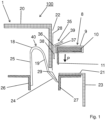
- Figure 1 shows schematically and by way of example a cross section through a part of the connecting device 100 as in Figure 7 and 8th shown.
- An insertion opening 28 is formed on the rear narrow side 21 for inserting the contact lug 11 of the busbar 8 into the Clamping point in the direction of arrow P.
- the clamping point is formed by a spring clip.
- This has a clamping spring 40 with a support wing 25, a clamping wing 19 and a loop 18 which connects the clamping wing 19 to the support wing 25 and which forms a spring and effects the restoring spring force on the clamping wing 19.
- the clamping wing 19 has a slight bend, its clamping end 24 is bent slightly upwards towards the front 21.
- the clamping spring 40 With the support wing 25, the clamping spring 40 is supported on a support rail 26 inside the installation switching device 1. With the clamping end 24, the clamping spring 40 presses an inserted connecting conductor, for example the contact lug 11, against a busbar 27. The electrical contact takes place between the busbar 27 and the contact lug 11, see Figure 2 and 3 .
- the busbar 27 and the support rail 26 can be parts of a common terminal frame, but they can also be designed as individual parts.
- the support rail 26 could also be designed as a housing projection. Further conductor pieces are then connected to the busbar 27 inside the installation switching device, which continue the current path from the terminal point inside the installation switching device 1.
- busbar 8 and the motor protection switch 1 are still separated from each other.
- the bus bar 8 can be inserted into the insertion opening 28 in the direction of arrow P, with the contact tab 11 in front become.
- Figure 2 shows the state in which the busbar 8 is inserted into the insertion opening 28 with the contact tab 11 first.
- the contact tab 11 pushes the clamping end 24 of the clamping spring 40 away.
- the free end of the contact tab 11 has a flat side that slides along the busbar 27, which is also designed with a flat surface.
- When inserted, see Figure 2 presses the clamping end 24 of the clamping wing 19 against the side of the end piece of the contact lug 11 facing the clamping wing 19.
- the area in which the clamping end 24 rests on the contact lug 11 is referred to as the clamping point 29.
- the contact point 30 Due to the pressure effect of the clamping end 24 of the clamping wing 19 on the contact lug 11, the side of the contact lug 11 opposite the clamping point 29 is pressed flat against the busbar 27.
- the area in which the side of the contact tab 11 opposite the clamping point 29 lies flat against the busbar 27 is referred to as the contact point 30.
- the electrical contact between the contact lug 11 and the busbar 27 takes place at the contact point 30. There the current flows from the contact lug 11 into the installation switching device 1 or out of the installation switching device 1 into the contact lug 11. There should therefore be a low electrical contact resistance at the contact point 30. If the pole rail with the contact lugs 11 is made of a highly conductive material, for example copper or a copper alloy, this can be achieved with a sufficiently large contact pressure from the clamping spring 40 and its clamping end 24 on the clamping point 29.
- a spring steel used to produce the clamping spring 40 is usually not a good electrical conductor; it is specifically optimized with regard to its spring-elastic properties.
- the clamping end 24 of the clamping spring 40 can cut into the contact lug 11, which is made of a highly conductive but less hard material, in the area of the clamping point 29.
- the clamping end 24 of the clamping wing 19 of the clamping spring 40 then becomes clamped.
- the busbar could then only be pulled out of the insertion opening 28 with increased effort; if pulled out several times, the clamping spring 40 or the Contact flag 11 takes damage.
- the insulating profile 9 is designed with a manually operable opening member 35, which, when actuated, pushes the clamping end 24 of the clamping spring away from the clamping point 29 and thus enables the contact tab 11 to be removed from the clamp without using an additional tool.
- the insulating profile 9 is designed with a manually operable opening member, as shown in FIG Figures 1 - 3 is shown.
- the opening member 35 is in the form of a double arm lever 35. Its pivot axis 36 is located on a molding 37 on the insulating profile 9, which protrudes a little from the insulating profile 9. This creates a pivot point for the double arm lever 35 that is spaced from the insulating profile 9 and is firmly connected to the insulating profile 9 and allows pivoting towards the insulating profile 9 and away from the insulating profile 9.
- a first arm 38 of the double arm lever 35 extends approximately parallel to the contact tab 11 in the direction of the clamping wing 19 of the clamping spring 40.
- a second arm 39 of the double arm lever 35 extends into the space outside the insulating profile 9 and can be operated by hand from the outside when the busbar 8 is inserted. In the embodiment shown here, which is only shown as an example, the second arm 39 is slightly angled so that it is easier to reach with a finger for actuation.
- Figure 1 shows the busbar separated from the installation switching device 1.
- Figure 2 shows the busbar 8 plugged onto the insertion opening 28 of the installation switching device 1.
- the free end of the first arm 38 of the opening member 35 ends here shortly before the clamping wing 19 of the clamping spring 40.
- Figure 3 shows the situation when the opening member 35 is actuated. Pressure on the second arm 39 in the direction of arrow D pivots the first arm 38 clockwise, which pushes the clamping end 24 of the clamping wing 19 away from the clamping point 29, indicated by the arrow F, and The contact tab 11 can be pulled out upwards, see arrow E.
- FIGS 4 - 6 differs from that in the Figures 1 -3 shown embodiment in that here the insulating profile 9 is additionally formed with a locking element 31, which has a locking element 32 adapted to it on the housing of the installation switching device 1, here in the example on the rear narrow side 23, interacts in a latching manner when the clamping spring 40 clamps the contact tab 11 with the clamping end 24 at the clamping point 29 and presses it against the busbar 27 at the contact point 30.
- the latching element 31 is a latching lug 33 on a latching bar 34 which is resiliently clamped on one side.
- the latching element 32 corresponding to it on the housing is a corresponding latching lug or a latching opening formed on the housing (not shown here in the figure).
- the locking element 31 in locking with the locking element 32 prevents the insulating profile 9 from shaking loose and thus also the busbar from shaking loose in an industrial environment, and thus supports the clamping effect of the clamping end 24 of the clamping spring 40 on the contact tab 11.
- the locking element can be used to remove the busbar 8 31 can be bent away without tools with one or more fingers so that the locking lug 33 releases the locking element 32, and the bus bar 8 can then be pulled out of the insertion opening 28 with the same hand or the other hand.
Landscapes
- Connections Arranged To Contact A Plurality Of Conductors (AREA)
Claims (6)
- Dispositif de connexion (100), qui présente au moins un appareil de commutation d'installation (1) avec un boîtier et avec au moins une borne sans vis et au moins un élément de connexion (8), l'élément de connexion (8) ayant un profilé isolant (9) et, disposé dans celui-ci, au moins un conducteur de connexion (10) avec au moins une languette de contact (11) disposée sur lui, la borne étant du type qui présente au moins un ressort de serrage (40) agissant comme ressort de pression sur un point de serrage (29) de la languette de contact (11) pour serrer la languette de contact (11) et pour presser un point de contact (30) de la languette de contact (11) sur une barre conductrice (27), et en ce que l'élément de connexion (8) est réalisé avec un organe d'ouverture (35) apte à être actionné manuellement, qui, lorsqu'il est actionné, éloigne le ressort de serrage (40) du point de serrage (29) et permet ainsi le retrait de la languette de contact (11) de la borne sans utiliser d'outil supplémentaire, caractérisé en ce que l'organe d'ouverture (35) est réalisé sous la forme d'un levier à double bras dont l'axe de pivotement (36) se trouve sur une conformation (37) sur le profilé isolant (9), la conformation (37) s'étendant sur une distance du profilé isolant (9), un premier bras (38) du levier à double bras s'étendant sensiblement parallèlement à la languette de contact (11) en direction d'une aile de serrage (19) du ressort de serrage (40), un deuxième bras (39) du levier à double bras (35) s'étendant dans l'espace situé à l'extérieur du profilé isolant (9) et étant apte à être actionné de l'extérieur manuellement lorsque l'élément de connexion (8) est enfiché.
- Dispositif de connexion (100) selon la revendication 1, caractérisé en ce que l'élément de connexion (8) est réalisé avec un organe d'encliquetage (31) qui coopère par encliquetage avec un élément d'encliquetage (32) adapté à lui sur le boîtier de l'appareil de commutation d'installation (1) lorsque le ressort de serrage (40) serre la languette de contact (11) au niveau du point de serrage (29) et la presse contre le rail conducteur (27) au niveau du point de contact (30).
- Dispositif de connexion (100) selon la revendication 2, caractérisé en ce que l'organe d'encliquetage (31) est un ergot d'encliquetage (33) sur une barre d'encliquetage (34) serrée élastiquement d'un côté, et en ce que l'élément d'encliquetage (32) correspondant sur le boîtier est un ergot d'encliquetage ou une ouverture d'encliquetage correspondant(e) formé(e) sur le boîtier.
- Dispositif de connexion (100) selon l'une quelconque des revendications précédentes, caractérisé en ce que l'élément de connexion (8) est une barre omnibus qui a un profilé isolant (9) et dans lequel le conducteur de connexion est une barre polaire disposée dans le profilé isolant (9), et en ce que l'organe d'ouverture (35) actionnable manuellement est formé sur le profilé isolant (9) .
- Dispositif de connexion (100) selon l'une des revendications 1 à 3, caractérisé en ce que l'élément de connexion est un connecteur à fiche pour établir une connexion électrique entre les bornes d'un disjoncteur moteur et d'un contacteur.
- Dispositif de connexion (100) selon l'une des revendications 1 à 3, caractérisé en ce que l'élément de connexion est un connecteur réversible.
Applications Claiming Priority (2)
| Application Number | Priority Date | Filing Date | Title |
|---|---|---|---|
| DE102015111229 | 2015-07-10 | ||
| DE102016110189.3A DE102016110189B4 (de) | 2015-07-10 | 2016-06-02 | Verbindungsvorrichtung mit Steckklemme |
Publications (2)
| Publication Number | Publication Date |
|---|---|
| EP3116067A1 EP3116067A1 (fr) | 2017-01-11 |
| EP3116067B1 true EP3116067B1 (fr) | 2024-02-28 |
Family
ID=56119419
Family Applications (1)
| Application Number | Title | Priority Date | Filing Date |
|---|---|---|---|
| EP16174157.4A Active EP3116067B1 (fr) | 2015-07-10 | 2016-06-13 | Dispositif de connexion comprenant une borne enfichable |
Country Status (1)
| Country | Link |
|---|---|
| EP (1) | EP3116067B1 (fr) |
Citations (2)
| Publication number | Priority date | Publication date | Assignee | Title |
|---|---|---|---|---|
| EP1667286A2 (fr) * | 2004-12-04 | 2006-06-07 | Weidmüller Interface GmbH & Co. KG | Dispositif pour une connexion électrique conductrice de deux bornes avec des barres conductrices |
| WO2010015308A1 (fr) * | 2008-08-05 | 2010-02-11 | Abb Ag | Appareil de commutation d'installation doté d'une connexion de bornes sans vis |
Family Cites Families (5)
| Publication number | Priority date | Publication date | Assignee | Title |
|---|---|---|---|---|
| FR2773274B1 (fr) | 1997-12-29 | 2000-02-11 | Schneider Electric Sa | Dispositif de connexion a cage elastique |
| DE20101435U1 (de) * | 2001-01-26 | 2002-06-06 | ABL SURSUM Bayerische Elektrozubehör GmbH & Co. KG, 91207 Lauf | Elektrogerät mit Anschlüssen für Einzeldraht und Sammelschiene |
| DE202010008028U1 (de) * | 2009-07-18 | 2010-12-30 | Weidmüller Interface GmbH & Co. KG | Anschlussvorrichtung für Leiter |
| FR2971097B1 (fr) * | 2011-01-31 | 2013-03-08 | Hager Electro Sas | Appareils electriques dotes de moyens de maintien d'un dispositif de pontage. |
| EP2843764B1 (fr) * | 2013-08-27 | 2020-11-11 | Weidmüller Interface GmbH & Co. KG | Borne de connexion électrique à ressort |
-
2016
- 2016-06-13 EP EP16174157.4A patent/EP3116067B1/fr active Active
Patent Citations (2)
| Publication number | Priority date | Publication date | Assignee | Title |
|---|---|---|---|---|
| EP1667286A2 (fr) * | 2004-12-04 | 2006-06-07 | Weidmüller Interface GmbH & Co. KG | Dispositif pour une connexion électrique conductrice de deux bornes avec des barres conductrices |
| WO2010015308A1 (fr) * | 2008-08-05 | 2010-02-11 | Abb Ag | Appareil de commutation d'installation doté d'une connexion de bornes sans vis |
Also Published As
| Publication number | Publication date |
|---|---|
| EP3116067A1 (fr) | 2017-01-11 |
Similar Documents
| Publication | Publication Date | Title |
|---|---|---|
| DE102008017245B4 (de) | Steckadapter für ein elektrisches Schaltgerät | |
| EP3324490B1 (fr) | Contact à serrage par ressort pour connecter un conducteur électrique, borne de connexion de conducteur et méthode de fabrication d'un contact à serrage par ressort | |
| EP3298659B1 (fr) | Borne de connexion de conducteur | |
| EP1515397B1 (fr) | Borne de connexion électrique à raccordement enfichable directe de conducteur électrique | |
| DE102006049773B4 (de) | Modulares Installationsschaltgerät | |
| DE202010008028U1 (de) | Anschlussvorrichtung für Leiter | |
| EP3275049B2 (fr) | Ensemble de serrage, borne à ressort et interrupteur comprenant cet ensemble de serrage | |
| EP2975708B1 (fr) | Systeme d'adaptateur dote d'un adaptateur pour rails collecteurs et module de raccordement d'adaptateur | |
| EP1818964B1 (fr) | Barrette de fusibles avec contacts de sortie latéraux et module adaptateur latéral | |
| EP3164913B1 (fr) | Adaptateur de connexion pour appareil électrique pour connecter des lignes d'alimentation électrique et système constitué d'un adaptateur de connexion et d'un appareil | |
| DE102013105263B3 (de) | Steckverbinder | |
| EP1949502A1 (fr) | Borne electrique pour cartes de circuits imprimes | |
| DE102006049772B4 (de) | Installationsschaltgerät | |
| EP3038213B1 (fr) | Borne de connection de cable destinee a serrer au moins un conducteur electrique | |
| DE102016110189B4 (de) | Verbindungsvorrichtung mit Steckklemme | |
| EP3116067B1 (fr) | Dispositif de connexion comprenant une borne enfichable | |
| DE202015102561U1 (de) | Leiteranschlussklemme | |
| DE102009045121B4 (de) | System zur Verteilung von elektrischer Energie und Verfahren zur Anbringung eines Adapters an einer Sammelschiene | |
| DE29916001U1 (de) | Installationsschalter | |
| EP3118933B1 (fr) | Dispositif de connexion comprenant une borne enfichable | |
| DE102005010662B4 (de) | System mit zumindest zwei mehrpoligen Leistungsschaltern, Schützen, Zeitrelais,Überlastrealis oder sonstigen Realis, Sanftstartern, Schaltgerätekombinationen | |
| EP1818963B1 (fr) | Colonne de sécurité dotée de contacts de sortie latéraux | |
| DE102016110176A1 (de) | Verbindungsvorrichtung mit Steckklemme | |
| DE1590086B2 (de) | Federklemme zur befestigung von zwei leitungsdrahtenden in elektrischen installationsgeraeten | |
| DE102016110174A1 (de) | Verbindungsvorrichtung mit Steckklemme |
Legal Events
| Date | Code | Title | Description |
|---|---|---|---|
| PUAI | Public reference made under article 153(3) epc to a published international application that has entered the european phase |
Free format text: ORIGINAL CODE: 0009012 |
|
| STAA | Information on the status of an ep patent application or granted ep patent |
Free format text: STATUS: THE APPLICATION HAS BEEN PUBLISHED |
|
| AK | Designated contracting states |
Kind code of ref document: A1 Designated state(s): AL AT BE BG CH CY CZ DE DK EE ES FI FR GB GR HR HU IE IS IT LI LT LU LV MC MK MT NL NO PL PT RO RS SE SI SK SM TR |
|
| AX | Request for extension of the european patent |
Extension state: BA ME |
|
| STAA | Information on the status of an ep patent application or granted ep patent |
Free format text: STATUS: REQUEST FOR EXAMINATION WAS MADE |
|
| 17P | Request for examination filed |
Effective date: 20170627 |
|
| STAA | Information on the status of an ep patent application or granted ep patent |
Free format text: STATUS: EXAMINATION IS IN PROGRESS |
|
| 17Q | First examination report despatched |
Effective date: 20190311 |
|
| GRAP | Despatch of communication of intention to grant a patent |
Free format text: ORIGINAL CODE: EPIDOSNIGR1 |
|
| STAA | Information on the status of an ep patent application or granted ep patent |
Free format text: STATUS: GRANT OF PATENT IS INTENDED |
|
| INTG | Intention to grant announced |
Effective date: 20231010 |
|
| GRAS | Grant fee paid |
Free format text: ORIGINAL CODE: EPIDOSNIGR3 |
|
| GRAA | (expected) grant |
Free format text: ORIGINAL CODE: 0009210 |
|
| STAA | Information on the status of an ep patent application or granted ep patent |
Free format text: STATUS: THE PATENT HAS BEEN GRANTED |
|
| RAP3 | Party data changed (applicant data changed or rights of an application transferred) |
Owner name: ABB SCHWEIZ AG |
|
| AK | Designated contracting states |
Kind code of ref document: B1 Designated state(s): AL AT BE BG CH CY CZ DE DK EE ES FI FR GB GR HR HU IE IS IT LI LT LU LV MC MK MT NL NO PL PT RO RS SE SI SK SM TR |
|
| REG | Reference to a national code |
Ref country code: GB Ref legal event code: FG4D Free format text: NOT ENGLISH |
|
| REG | Reference to a national code |
Ref country code: CH Ref legal event code: EP |
|
| REG | Reference to a national code |
Ref country code: DE Ref legal event code: R096 Ref document number: 502016016389 Country of ref document: DE |
|
| REG | Reference to a national code |
Ref country code: IE Ref legal event code: FG4D Free format text: LANGUAGE OF EP DOCUMENT: GERMAN |
|
| REG | Reference to a national code |
Ref country code: LT Ref legal event code: MG9D |
|
| PG25 | Lapsed in a contracting state [announced via postgrant information from national office to epo] |
Ref country code: IS Free format text: LAPSE BECAUSE OF FAILURE TO SUBMIT A TRANSLATION OF THE DESCRIPTION OR TO PAY THE FEE WITHIN THE PRESCRIBED TIME-LIMIT Effective date: 20240628 |
|
| REG | Reference to a national code |
Ref country code: NL Ref legal event code: MP Effective date: 20240228 |
|
| PG25 | Lapsed in a contracting state [announced via postgrant information from national office to epo] |
Ref country code: LT Free format text: LAPSE BECAUSE OF FAILURE TO SUBMIT A TRANSLATION OF THE DESCRIPTION OR TO PAY THE FEE WITHIN THE PRESCRIBED TIME-LIMIT Effective date: 20240228 |
|
| PG25 | Lapsed in a contracting state [announced via postgrant information from national office to epo] |
Ref country code: GR Free format text: LAPSE BECAUSE OF FAILURE TO SUBMIT A TRANSLATION OF THE DESCRIPTION OR TO PAY THE FEE WITHIN THE PRESCRIBED TIME-LIMIT Effective date: 20240529 |
|
| PG25 | Lapsed in a contracting state [announced via postgrant information from national office to epo] |
Ref country code: HR Free format text: LAPSE BECAUSE OF FAILURE TO SUBMIT A TRANSLATION OF THE DESCRIPTION OR TO PAY THE FEE WITHIN THE PRESCRIBED TIME-LIMIT Effective date: 20240228 Ref country code: NL Free format text: LAPSE BECAUSE OF FAILURE TO SUBMIT A TRANSLATION OF THE DESCRIPTION OR TO PAY THE FEE WITHIN THE PRESCRIBED TIME-LIMIT Effective date: 20240228 Ref country code: RS Free format text: LAPSE BECAUSE OF FAILURE TO SUBMIT A TRANSLATION OF THE DESCRIPTION OR TO PAY THE FEE WITHIN THE PRESCRIBED TIME-LIMIT Effective date: 20240528 |
|
| PG25 | Lapsed in a contracting state [announced via postgrant information from national office to epo] |
Ref country code: ES Free format text: LAPSE BECAUSE OF FAILURE TO SUBMIT A TRANSLATION OF THE DESCRIPTION OR TO PAY THE FEE WITHIN THE PRESCRIBED TIME-LIMIT Effective date: 20240228 |
|
| PG25 | Lapsed in a contracting state [announced via postgrant information from national office to epo] |
Ref country code: RS Free format text: LAPSE BECAUSE OF FAILURE TO SUBMIT A TRANSLATION OF THE DESCRIPTION OR TO PAY THE FEE WITHIN THE PRESCRIBED TIME-LIMIT Effective date: 20240528 Ref country code: NO Free format text: LAPSE BECAUSE OF FAILURE TO SUBMIT A TRANSLATION OF THE DESCRIPTION OR TO PAY THE FEE WITHIN THE PRESCRIBED TIME-LIMIT Effective date: 20240528 Ref country code: NL Free format text: LAPSE BECAUSE OF FAILURE TO SUBMIT A TRANSLATION OF THE DESCRIPTION OR TO PAY THE FEE WITHIN THE PRESCRIBED TIME-LIMIT Effective date: 20240228 Ref country code: LT Free format text: LAPSE BECAUSE OF FAILURE TO SUBMIT A TRANSLATION OF THE DESCRIPTION OR TO PAY THE FEE WITHIN THE PRESCRIBED TIME-LIMIT Effective date: 20240228 Ref country code: IS Free format text: LAPSE BECAUSE OF FAILURE TO SUBMIT A TRANSLATION OF THE DESCRIPTION OR TO PAY THE FEE WITHIN THE PRESCRIBED TIME-LIMIT Effective date: 20240628 Ref country code: HR Free format text: LAPSE BECAUSE OF FAILURE TO SUBMIT A TRANSLATION OF THE DESCRIPTION OR TO PAY THE FEE WITHIN THE PRESCRIBED TIME-LIMIT Effective date: 20240228 Ref country code: GR Free format text: LAPSE BECAUSE OF FAILURE TO SUBMIT A TRANSLATION OF THE DESCRIPTION OR TO PAY THE FEE WITHIN THE PRESCRIBED TIME-LIMIT Effective date: 20240529 Ref country code: FI Free format text: LAPSE BECAUSE OF FAILURE TO SUBMIT A TRANSLATION OF THE DESCRIPTION OR TO PAY THE FEE WITHIN THE PRESCRIBED TIME-LIMIT Effective date: 20240228 Ref country code: ES Free format text: LAPSE BECAUSE OF FAILURE TO SUBMIT A TRANSLATION OF THE DESCRIPTION OR TO PAY THE FEE WITHIN THE PRESCRIBED TIME-LIMIT Effective date: 20240228 Ref country code: BG Free format text: LAPSE BECAUSE OF FAILURE TO SUBMIT A TRANSLATION OF THE DESCRIPTION OR TO PAY THE FEE WITHIN THE PRESCRIBED TIME-LIMIT Effective date: 20240228 |
|
| PG25 | Lapsed in a contracting state [announced via postgrant information from national office to epo] |
Ref country code: PT Free format text: LAPSE BECAUSE OF FAILURE TO SUBMIT A TRANSLATION OF THE DESCRIPTION OR TO PAY THE FEE WITHIN THE PRESCRIBED TIME-LIMIT Effective date: 20240628 Ref country code: PL Free format text: LAPSE BECAUSE OF FAILURE TO SUBMIT A TRANSLATION OF THE DESCRIPTION OR TO PAY THE FEE WITHIN THE PRESCRIBED TIME-LIMIT Effective date: 20240228 |
|
| PG25 | Lapsed in a contracting state [announced via postgrant information from national office to epo] |
Ref country code: SE Free format text: LAPSE BECAUSE OF FAILURE TO SUBMIT A TRANSLATION OF THE DESCRIPTION OR TO PAY THE FEE WITHIN THE PRESCRIBED TIME-LIMIT Effective date: 20240228 Ref country code: PT Free format text: LAPSE BECAUSE OF FAILURE TO SUBMIT A TRANSLATION OF THE DESCRIPTION OR TO PAY THE FEE WITHIN THE PRESCRIBED TIME-LIMIT Effective date: 20240628 Ref country code: PL Free format text: LAPSE BECAUSE OF FAILURE TO SUBMIT A TRANSLATION OF THE DESCRIPTION OR TO PAY THE FEE WITHIN THE PRESCRIBED TIME-LIMIT Effective date: 20240228 Ref country code: LV Free format text: LAPSE BECAUSE OF FAILURE TO SUBMIT A TRANSLATION OF THE DESCRIPTION OR TO PAY THE FEE WITHIN THE PRESCRIBED TIME-LIMIT Effective date: 20240228 |
|
| PG25 | Lapsed in a contracting state [announced via postgrant information from national office to epo] |
Ref country code: DK Free format text: LAPSE BECAUSE OF FAILURE TO SUBMIT A TRANSLATION OF THE DESCRIPTION OR TO PAY THE FEE WITHIN THE PRESCRIBED TIME-LIMIT Effective date: 20240228 |
|
| PG25 | Lapsed in a contracting state [announced via postgrant information from national office to epo] |
Ref country code: SM Free format text: LAPSE BECAUSE OF FAILURE TO SUBMIT A TRANSLATION OF THE DESCRIPTION OR TO PAY THE FEE WITHIN THE PRESCRIBED TIME-LIMIT Effective date: 20240228 |
|
| PG25 | Lapsed in a contracting state [announced via postgrant information from national office to epo] |
Ref country code: EE Free format text: LAPSE BECAUSE OF FAILURE TO SUBMIT A TRANSLATION OF THE DESCRIPTION OR TO PAY THE FEE WITHIN THE PRESCRIBED TIME-LIMIT Effective date: 20240228 Ref country code: CZ Free format text: LAPSE BECAUSE OF FAILURE TO SUBMIT A TRANSLATION OF THE DESCRIPTION OR TO PAY THE FEE WITHIN THE PRESCRIBED TIME-LIMIT Effective date: 20240228 |
|
| PG25 | Lapsed in a contracting state [announced via postgrant information from national office to epo] |
Ref country code: SK Free format text: LAPSE BECAUSE OF FAILURE TO SUBMIT A TRANSLATION OF THE DESCRIPTION OR TO PAY THE FEE WITHIN THE PRESCRIBED TIME-LIMIT Effective date: 20240228 |
|
| PG25 | Lapsed in a contracting state [announced via postgrant information from national office to epo] |
Ref country code: SM Free format text: LAPSE BECAUSE OF FAILURE TO SUBMIT A TRANSLATION OF THE DESCRIPTION OR TO PAY THE FEE WITHIN THE PRESCRIBED TIME-LIMIT Effective date: 20240228 Ref country code: SK Free format text: LAPSE BECAUSE OF FAILURE TO SUBMIT A TRANSLATION OF THE DESCRIPTION OR TO PAY THE FEE WITHIN THE PRESCRIBED TIME-LIMIT Effective date: 20240228 Ref country code: RO Free format text: LAPSE BECAUSE OF FAILURE TO SUBMIT A TRANSLATION OF THE DESCRIPTION OR TO PAY THE FEE WITHIN THE PRESCRIBED TIME-LIMIT Effective date: 20240228 Ref country code: EE Free format text: LAPSE BECAUSE OF FAILURE TO SUBMIT A TRANSLATION OF THE DESCRIPTION OR TO PAY THE FEE WITHIN THE PRESCRIBED TIME-LIMIT Effective date: 20240228 Ref country code: DK Free format text: LAPSE BECAUSE OF FAILURE TO SUBMIT A TRANSLATION OF THE DESCRIPTION OR TO PAY THE FEE WITHIN THE PRESCRIBED TIME-LIMIT Effective date: 20240228 Ref country code: CZ Free format text: LAPSE BECAUSE OF FAILURE TO SUBMIT A TRANSLATION OF THE DESCRIPTION OR TO PAY THE FEE WITHIN THE PRESCRIBED TIME-LIMIT Effective date: 20240228 |
|
| REG | Reference to a national code |
Ref country code: DE Ref legal event code: R097 Ref document number: 502016016389 Country of ref document: DE |
|
| PLBE | No opposition filed within time limit |
Free format text: ORIGINAL CODE: 0009261 |
|
| STAA | Information on the status of an ep patent application or granted ep patent |
Free format text: STATUS: NO OPPOSITION FILED WITHIN TIME LIMIT |
|
| PG25 | Lapsed in a contracting state [announced via postgrant information from national office to epo] |
Ref country code: MC Free format text: LAPSE BECAUSE OF FAILURE TO SUBMIT A TRANSLATION OF THE DESCRIPTION OR TO PAY THE FEE WITHIN THE PRESCRIBED TIME-LIMIT Effective date: 20240228 |
|
| REG | Reference to a national code |
Ref country code: CH Ref legal event code: PL |
|
| 26N | No opposition filed |
Effective date: 20241129 |
|
| PG25 | Lapsed in a contracting state [announced via postgrant information from national office to epo] |
Ref country code: LU Free format text: LAPSE BECAUSE OF NON-PAYMENT OF DUE FEES Effective date: 20240613 |
|
| GBPC | Gb: european patent ceased through non-payment of renewal fee |
Effective date: 20240613 |
|
| PG25 | Lapsed in a contracting state [announced via postgrant information from national office to epo] |
Ref country code: IE Free format text: LAPSE BECAUSE OF NON-PAYMENT OF DUE FEES Effective date: 20240613 |
|
| PG25 | Lapsed in a contracting state [announced via postgrant information from national office to epo] |
Ref country code: CH Free format text: LAPSE BECAUSE OF NON-PAYMENT OF DUE FEES Effective date: 20240630 Ref country code: SI Free format text: LAPSE BECAUSE OF FAILURE TO SUBMIT A TRANSLATION OF THE DESCRIPTION OR TO PAY THE FEE WITHIN THE PRESCRIBED TIME-LIMIT Effective date: 20240228 Ref country code: BE Free format text: LAPSE BECAUSE OF NON-PAYMENT OF DUE FEES Effective date: 20240630 |
|
| PG25 | Lapsed in a contracting state [announced via postgrant information from national office to epo] |
Ref country code: GB Free format text: LAPSE BECAUSE OF NON-PAYMENT OF DUE FEES Effective date: 20240613 |
|
| REG | Reference to a national code |
Ref country code: BE Ref legal event code: MM Effective date: 20240630 |
|
| PGFP | Annual fee paid to national office [announced via postgrant information from national office to epo] |
Ref country code: DE Payment date: 20250618 Year of fee payment: 10 |
|
| PGFP | Annual fee paid to national office [announced via postgrant information from national office to epo] |
Ref country code: FR Payment date: 20250625 Year of fee payment: 10 |
|
| REG | Reference to a national code |
Ref country code: AT Ref legal event code: MM01 Ref document number: 1662116 Country of ref document: AT Kind code of ref document: T Effective date: 20240613 |
|
| PGFP | Annual fee paid to national office [announced via postgrant information from national office to epo] |
Ref country code: IT Payment date: 20250624 Year of fee payment: 10 |
|
| PG25 | Lapsed in a contracting state [announced via postgrant information from national office to epo] |
Ref country code: AT Free format text: LAPSE BECAUSE OF NON-PAYMENT OF DUE FEES Effective date: 20240613 |
|
| PG25 | Lapsed in a contracting state [announced via postgrant information from national office to epo] |
Ref country code: CY Free format text: LAPSE BECAUSE OF FAILURE TO SUBMIT A TRANSLATION OF THE DESCRIPTION OR TO PAY THE FEE WITHIN THE PRESCRIBED TIME-LIMIT; INVALID AB INITIO Effective date: 20160613 |
|
| PG25 | Lapsed in a contracting state [announced via postgrant information from national office to epo] |
Ref country code: HU Free format text: LAPSE BECAUSE OF FAILURE TO SUBMIT A TRANSLATION OF THE DESCRIPTION OR TO PAY THE FEE WITHIN THE PRESCRIBED TIME-LIMIT; INVALID AB INITIO Effective date: 20160613 |