EP3118979A1 - Elektromotor - Google Patents
Elektromotor Download PDFInfo
- Publication number
- EP3118979A1 EP3118979A1 EP15761469.4A EP15761469A EP3118979A1 EP 3118979 A1 EP3118979 A1 EP 3118979A1 EP 15761469 A EP15761469 A EP 15761469A EP 3118979 A1 EP3118979 A1 EP 3118979A1
- Authority
- EP
- European Patent Office
- Prior art keywords
- angle
- phase
- coil
- advance
- coils
- Prior art date
- Legal status (The legal status is an assumption and is not a legal conclusion. Google has not performed a legal analysis and makes no representation as to the accuracy of the status listed.)
- Granted
Links
- 238000004804 winding Methods 0.000 claims abstract description 68
- 239000013598 vector Substances 0.000 claims description 41
- 239000003638 chemical reducing agent Substances 0.000 description 9
- 230000009467 reduction Effects 0.000 description 8
- 230000007246 mechanism Effects 0.000 description 7
- 230000002093 peripheral effect Effects 0.000 description 5
- 230000006866 deterioration Effects 0.000 description 4
- 230000006872 improvement Effects 0.000 description 4
- 238000000034 method Methods 0.000 description 3
- 230000001846 repelling effect Effects 0.000 description 3
- 230000000694 effects Effects 0.000 description 2
- 230000002411 adverse Effects 0.000 description 1
- 230000008859 change Effects 0.000 description 1
- 239000004020 conductor Substances 0.000 description 1
- 210000003298 dental enamel Anatomy 0.000 description 1
- 238000010586 diagram Methods 0.000 description 1
- 239000000428 dust Substances 0.000 description 1
- 239000000696 magnetic material Substances 0.000 description 1
- 239000006247 magnetic powder Substances 0.000 description 1
- 238000004519 manufacturing process Methods 0.000 description 1
- 239000002184 metal Substances 0.000 description 1
- 238000012986 modification Methods 0.000 description 1
- 230000004048 modification Effects 0.000 description 1
- 238000003825 pressing Methods 0.000 description 1
- 238000000926 separation method Methods 0.000 description 1
Images



Classifications
-
- H—ELECTRICITY
- H02—GENERATION; CONVERSION OR DISTRIBUTION OF ELECTRIC POWER
- H02K—DYNAMO-ELECTRIC MACHINES
- H02K23/00—DC commutator motors or generators having mechanical commutator; Universal AC/DC commutator motors
- H02K23/26—DC commutator motors or generators having mechanical commutator; Universal AC/DC commutator motors characterised by the armature windings
- H02K23/38—DC commutator motors or generators having mechanical commutator; Universal AC/DC commutator motors characterised by the armature windings having winding or connection for improving commutation, e.g. equipotential connection
-
- H—ELECTRICITY
- H02—GENERATION; CONVERSION OR DISTRIBUTION OF ELECTRIC POWER
- H02K—DYNAMO-ELECTRIC MACHINES
- H02K1/00—Details of the magnetic circuit
- H02K1/06—Details of the magnetic circuit characterised by the shape, form or construction
- H02K1/12—Stationary parts of the magnetic circuit
- H02K1/17—Stator cores with permanent magnets
-
- H—ELECTRICITY
- H02—GENERATION; CONVERSION OR DISTRIBUTION OF ELECTRIC POWER
- H02K—DYNAMO-ELECTRIC MACHINES
- H02K1/00—Details of the magnetic circuit
- H02K1/06—Details of the magnetic circuit characterised by the shape, form or construction
- H02K1/22—Rotating parts of the magnetic circuit
- H02K1/24—Rotor cores with salient poles ; Variable reluctance rotors
-
- H—ELECTRICITY
- H02—GENERATION; CONVERSION OR DISTRIBUTION OF ELECTRIC POWER
- H02K—DYNAMO-ELECTRIC MACHINES
- H02K1/00—Details of the magnetic circuit
- H02K1/06—Details of the magnetic circuit characterised by the shape, form or construction
- H02K1/22—Rotating parts of the magnetic circuit
- H02K1/26—Rotor cores with slots for windings
-
- H—ELECTRICITY
- H02—GENERATION; CONVERSION OR DISTRIBUTION OF ELECTRIC POWER
- H02K—DYNAMO-ELECTRIC MACHINES
- H02K13/00—Structural associations of current collectors with motors or generators, e.g. brush mounting plates or connections to windings; Disposition of current collectors in motors or generators; Arrangements for improving commutation
- H02K13/006—Structural associations of commutators
-
- H—ELECTRICITY
- H02—GENERATION; CONVERSION OR DISTRIBUTION OF ELECTRIC POWER
- H02K—DYNAMO-ELECTRIC MACHINES
- H02K23/00—DC commutator motors or generators having mechanical commutator; Universal AC/DC commutator motors
- H02K23/26—DC commutator motors or generators having mechanical commutator; Universal AC/DC commutator motors characterised by the armature windings
-
- H—ELECTRICITY
- H02—GENERATION; CONVERSION OR DISTRIBUTION OF ELECTRIC POWER
- H02K—DYNAMO-ELECTRIC MACHINES
- H02K3/00—Details of windings
- H02K3/04—Windings characterised by the conductor shape, form or construction, e.g. with bar conductors
- H02K3/12—Windings characterised by the conductor shape, form or construction, e.g. with bar conductors arranged in slots
-
- H—ELECTRICITY
- H02—GENERATION; CONVERSION OR DISTRIBUTION OF ELECTRIC POWER
- H02K—DYNAMO-ELECTRIC MACHINES
- H02K3/00—Details of windings
- H02K3/04—Windings characterised by the conductor shape, form or construction, e.g. with bar conductors
- H02K3/18—Windings for salient poles
-
- H—ELECTRICITY
- H02—GENERATION; CONVERSION OR DISTRIBUTION OF ELECTRIC POWER
- H02K—DYNAMO-ELECTRIC MACHINES
- H02K3/00—Details of windings
- H02K3/04—Windings characterised by the conductor shape, form or construction, e.g. with bar conductors
- H02K3/28—Layout of windings or of connections between windings
-
- H—ELECTRICITY
- H02—GENERATION; CONVERSION OR DISTRIBUTION OF ELECTRIC POWER
- H02K—DYNAMO-ELECTRIC MACHINES
- H02K7/00—Arrangements for handling mechanical energy structurally associated with dynamo-electric machines, e.g. structural association with mechanical driving motors or auxiliary dynamo-electric machines
- H02K7/08—Structural association with bearings
-
- H—ELECTRICITY
- H02—GENERATION; CONVERSION OR DISTRIBUTION OF ELECTRIC POWER
- H02K—DYNAMO-ELECTRIC MACHINES
- H02K7/00—Arrangements for handling mechanical energy structurally associated with dynamo-electric machines, e.g. structural association with mechanical driving motors or auxiliary dynamo-electric machines
- H02K7/10—Structural association with clutches, brakes, gears, pulleys or mechanical starters
-
- H—ELECTRICITY
- H02—GENERATION; CONVERSION OR DISTRIBUTION OF ELECTRIC POWER
- H02K—DYNAMO-ELECTRIC MACHINES
- H02K2213/00—Specific aspects, not otherwise provided for and not covered by codes H02K2201/00 - H02K2211/00
- H02K2213/03—Machines characterised by numerical values, ranges, mathematical expressions or similar information
-
- H—ELECTRICITY
- H02—GENERATION; CONVERSION OR DISTRIBUTION OF ELECTRIC POWER
- H02K—DYNAMO-ELECTRIC MACHINES
- H02K7/00—Arrangements for handling mechanical energy structurally associated with dynamo-electric machines, e.g. structural association with mechanical driving motors or auxiliary dynamo-electric machines
- H02K7/10—Structural association with clutches, brakes, gears, pulleys or mechanical starters
- H02K7/116—Structural association with clutches, brakes, gears, pulleys or mechanical starters with gears
- H02K7/1163—Structural association with clutches, brakes, gears, pulleys or mechanical starters with gears where at least two gears have non-parallel axes without having orbital motion
- H02K7/1166—Structural association with clutches, brakes, gears, pulleys or mechanical starters with gears where at least two gears have non-parallel axes without having orbital motion comprising worm and worm-wheel
Definitions
- the present invention relates to an electric motor.
- a DC motor with a brush in which motor magnets are disposed on the inner peripheral surface of a bottomed cylindrical yoke and an armature is rotatably provided on the inside of the motor magnets in a radial direction, is known as an electric motor (for example, see PTL 1).
- the armature includes an armature core, armature coils, and a commutator.
- the armature core includes a plurality of teeth that are provided on the outer periphery of an annular core body externally fitted and fixed to a rotating shaft and radially extend outward in the radial direction.
- the armature coil is wound on each tooth of the armature core via a slot between the teeth.
- the commutator is provided on the rotating shaft so as to rotate integrally with the armature core.
- the commutator includes a plurality of segments that are disposed side by side in a circumferential direction in a state in which the segments are insulated from each other. Terminal portions of the respective armature coils are connected to these segments.
- a plurality of brushes come into sliding contact with the segments.
- DC current is supplied to each armature coil through the segment by the brushes, the armature and the rotating shaft are rotated by a magnetic attractive force or a repelling force that is generated between a magnetic field formed on the armature core and the motor magnets. Since the segments with which the brushes come into sliding contact are sequentially changed by the rotation of the armature and the rotating shaft, the switching of the direction of current flowing in the armature coil, that is, so-called rectification is performed. Then, the armature is continuously rotated and a rotational output is taken out of the rotating shaft.
- An object of the invention is to provide an electric motor that can lengthen the lifespan of brushes by the improvement of rectification performance.
- an electric motor includes: a motor magnet in which a plurality of magnetic poles are arranged in a circumferential direction; a rotating shaft that is rotatably provided inside the motor magnet; an armature core that is mounted on the rotating shaft and includes a plurality of teeth radially extending outward in a radial direction and a plurality of slots formed between the teeth; coils that are wound on each of the teeth in a concentrated winding manner; a commutator which is provided so as to rotate integrally with the rotating shaft and on which a plurality of segments are disposed in the circumferential direction; and an anode brush and a cathode brush that supply power to the coils through the segments.
- Three coils are wound on each of the teeth, and the number of turns of one coil among the three coils is set to be smaller than the number of turns of each of the other two coils.
- the number of the magnetic poles is set to four, the number of the slots is set to six, and the number of the segments is set to eighteen; and the three coils wound on each tooth are formed of one forward winding coil that is wound in a forward direction and two reverse winding coils wound in a reverse direction.
- the forward winding coils wound to the respective phases are respectively referred to as a U phase, a V phase, and a W phase
- the reverse winding coils wound to the respective phases are respectively referred to as a -U phase, a -V phase, and a -W phase
- the coils of the U phase, the -W phase, the -W phase, the V phase, the -U phase, the -U phase, the W phase, the -V phase, and the -V phase are electrically connected in this order between the adjacent segments.
- the number of turns of one coil among the one forward winding coil and the two reverse winding coils, which are wound is set to be smaller than the number of turns of each of the other two coils.
- the three coils are an advance-angle coil of which a magnetomotive force vector is directed to an advance-angle side, a delay-angle coil of which a magnetomotive force vector is directed to a delay-angle side, and a normal coil of which a magnetomotive force vector is not directed to either the advance-angle side or the delay-angle side.
- T1 the number of turns of the advance-angle coil
- T2 the number of turns of the normal coil
- T3 the number of turns of the delay-angle coil
- the three coils are an advance-angle coil of which a magnetomotive force vector is directed to an advance-angle side, a delay-angle coil of which a magnetomotive force vector is directed to a delay-angle side, and a normal coil of which a magnetomotive force vector is not directed to either the advance-angle side or the delay-angle side.
- T1 the number of turns of the advance-angle coil
- T2 the number of turns of the normal coil
- T3 the number of turns of the delay-angle coil
- an advance angle ⁇ 1 of the magnetomotive force vector of the advance-angle coil satisfies 0° ⁇ 1 ⁇ 20°
- a delay angle ⁇ 2 of the magnetomotive force vector of the delay-angle coil satisfies 0° ⁇ 2 ⁇ 20°
- an advance angle ⁇ 3 of the position of the anode brush satisfies 3° ⁇ 10°
- T1, T2, and T3 are set so as to satisfy T2>T3>T1.
- the three coils are an advance-angle coil of which a magnetomotive force vector is directed to an advance-angle side, a delay-angle coil of which a magnetomotive force vector is directed to a delay-angle side, and a normal coil of which a magnetomotive force vector is not directed to either the advance-angle side or the delay-angle side.
- T1 the number of turns of the advance-angle coil
- T2 the number of turns of the normal coil
- T3 the number of turns of the delay-angle coil
- the electric motor since the number of turns of one coil is set to be smaller than the number of turns of each of the other two coils, it is possible to reduce an influence of the deterioration of rectification performance that is caused by the discordance of the magnetomotive force vectors generated by the three coils. Further, it is possible to lengthen the lifespan of the brushes by the improvement of rectification.
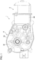
- FIG. 1 is a side view showing the appearance of a motor with a speed reducer to which an electric motor according to the invention is applied.
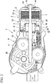
- FIG. 2 is a longitudinal sectional view of the motor with a speed reducer.
- a motor 1 with a speed reducer is used to drive, for example, windshield wipers of an automobile.
- the motor 1 with a speed reducer includes an electric motor 2 and a speed reduction mechanism 4 that is connected to a rotating shaft 3 of the electric motor 2.
- the electric motor 2 includes a yoke 5 that also functions as a bottomed cylindrical motor housing and an armature 6 that is rotatably provided in the yoke 5.
- a cylinder portion 53 of the yoke 5 is formed in a substantially cylindrical shape, and a motor magnet 7 is provided on the inner peripheral surface of the cylinder portion 53.
- Four magnetic poles are arranged on the inner peripheral surface of the motor magnet 7 so that N poles and S poles are alternated in a circumferential direction.
- the sliding bearing 18 has a function to align the rotating shaft 3.
- An outer flange 52 is provided at an opening of the cylinder portion 53, and an end portion of a gear housing 23 of the speed reduction mechanism 4 is fixed to the outer flange 52. Accordingly, the electric motor 2 and the speed reduction mechanism 4 are integrally connected to each other.
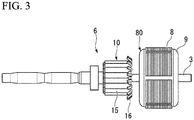
- FIG. 3 is a side view showing the appearance of the armature.
- the armature 6 includes an armature body 80 that is externally fitted and fixed to the rotating shaft 3, and a commutator 10 that is disposed at the other end side of the rotating shaft 3 (the speed reduction mechanism 4 side of the rotating shaft 3).
- the armature body 80 includes an armature core 8 and an armature coil 9 that is wound on the armature core 8.
- the armature core 8 is formed of a laminated core in which core plates punched by pressing or the like and made of a magnetic material are laminated in the axial direction, or a dust core that is press-molded with soft magnetic powder.
- an armature core 8 includes an annular core body 11.
- a through hole 11a into which the rotating shaft 3 is press-fitted is formed at the center of the core body 11.
- six teeth 12 are radially provided on the outer peripheral portion of the core body 11 at regular intervals in the circumferential direction.
- Each of the teeth 12 is formed in a substantially T shape in a plan view when seen in the axial direction.
- Each of the teeth 12 includes a winding drum part 12a that radially protrudes from the core body 11 in the radial direction, and a flange portion 12b that extends from the end of the winding drum part 12a in the circumferential direction and forms the outer periphery of the armature core 8.
- the commutator 10 is externally fitted and fixed to a side of the rotating shaft 3 closer to the other end side of the rotating shaft 3 (the speed reduction mechanism 4 side of the rotating shaft 3) than the armature core 8.
- a plurality of segments 15, which are made of a conductive material, are mounted on the outer peripheral surface of the commutator 10. Eighteen segments 15, of which the number is three times the number of the teeth 12 and the slots 13 of the armature core 8, are mounted.
- the segment 15 is formed of a plate-like metal piece that is long in the axial direction, and the segments 15 are fixed in parallel at regular intervals in the circumferential direction in a state in which the segments 15 are insulated from each other.
- the electric motor 2 is formed as a so-called 4-pole, 6-slot, 18-segment electric motor of which the number of magnetic poles is set to four, the number of slots 13 is set to six, and the number of segments 15 is set to eighteen.
- a riser 16 which is bent so as to be folded back toward the outer diameter side, is molded integrally with an end portion of each segment 15 facing the armature core 8. Terminal portions of the armature coil 9 are wound around the risers 16 and are fixed to the risers 16 by fusing or the like. Accordingly, the segment 15 and the armature coil 9 corresponding thereto are electrically connected to each other.
- the commutator 10 having the above-mentioned structure faces the gear housing 23 of the speed reduction mechanism 4.
- a gear group 41 of the speed reduction mechanism 4 is housed in the gear housing 23.
- a brush housing portion 22 is molded integrally with the side of the gear housing 23 facing the electric motor 2, and the commutator 10 of the electric motor 2 faces the brush housing portion 22.
- a brush 21 is housed in the brush housing portion 22 so as to freely protrude/recede through a holder stay or a brush holder (not shown).
- the brush 21 is used to supply power from an external power source (for example, a battery mounted on an automobile, or the like) to the commutator 10.
- the brush 21 is biased toward the commutator 10 by a spring (not shown), and an end of the brush 21 comes into sliding contact with the segments 15.
- the brush 21 includes a low-speed brush (an anode brush) 21a and a high-speed brush (an anode brush) 21b that are connected to an anode, and a common brush (a cathode brush) 21c that is connected to a cathode used in common to the low-speed brush 21a and the high-speed brush 21b.
- the low-speed brush 21a and the common brush 21c are disposed at an interval of 90° as a mechanical angle in a circumferential direction so as to correspond to the magnetic pole pitch of the motor magnet 7 (an electrical angle of 180°).
- the high-speed brush 21b is disposed at a position that is advanced from the common brush 21c by an angle slightly larger than the magnetic pole pitch of the motor magnet 7. Additionally, the advance angle of the high-speed brush 21b is set to, for example, 30°.
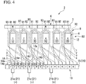
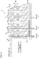
- FIG. 4 is a development view of the armature. A gap between the adjacent teeth corresponds to the slot.
- FIG. 5 is a view showing the winding direction of the winding wire and is a view showing the armature from the rear side on which the commutator is not disposed.
- each segment 15, each tooth 12, and the formed armature coil 9 will be described by denoting reference numerals in FIG. 4 .
- the segments which are disposed at positions opposite to each other by 180°, are electrically connected to each other by a connecting wire (not shown) or the like. Accordingly, the segments 15 which have the same condition with respect to the brush are denoted by the same reference numerals of 1 to 9.
- a U phase, a V phase, and a W phase are assigned to each tooth 12 in this order in the circumferential direction. That is, the first tooth 12 and the fourth tooth 12 correspond to a U phase, the second tooth 12 and the fifth tooth 12 correspond to a V phase, and the third tooth 12 and the sixth tooth 12 correspond to a W phase.
- the position corresponding to the first is regarded as a position corresponding to the first tooth 12.
- a direction in which the winding wire 14 is wound on each tooth 12 clockwise will be described as a forward direction and a direction in which the winding wire 14 is wound on each tooth 12 counterclockwise will be described as a reverse direction.
- the winding wire 14 is led into the slot 13 between the first and sixth teeth 12 existing near the first segment 15. Further, the winding wire 14 is wound on each tooth 12 in the forward direction in a concentrated winding manner.
- the winding wire 14 is led out of the slot 13 between the first and second teeth 12, and is wound around the riser 16 of the second segment 15 adjacent to the first segment 15. Then, a winding terminal end 14b is connected to the second segment 15. Accordingly, a U-phase first coil 91, which is wound on the first tooth 12 in the forward direction, is formed between the first and second segments 15.
- the winding wire 14 of which the winding start end 14a is wound around the riser 16 of the fifth segment 15 is led into the slot 13 between the first and second teeth 12. Then, the winding wire 14 is wound on the first tooth 12 in the reverse direction in a concentrated winding manner.
- the winding wire 14 is led out of the slot 13 between the first and sixth teeth 12, and is wound around the riser 16 of the sixth segment 15 adjacent to the fifth segment 15. Then, the winding terminal end 14b is connected to the sixth segment 15. Accordingly, a "-U"-phase second coil 92, which is wound on the first tooth 12 in the reverse direction, is formed between the fifth and sixth segments 15.
- the winding wire 14 of which the winding start end 14a is wound around the riser 16 of the sixth segment 15 is led into the slot 13 between the first and second teeth 12. Then, the winding wire 14 is wound on the first tooth 12 in the reverse direction in a concentrated winding manner.
- the winding wire 14 is led out of the slot 13 between the first and sixth teeth 12, and is wound around the riser 16 of the seventh segment 15 adjacent to the sixth segment 15. Then, the winding terminal end 14b is connected to the seventh segment 15. Accordingly, a "-U"-phase third coil 93, which is wound on the first tooth 12 in the reverse direction, is formed between the sixth and seventh segments 15.
- the armature coil 9, which includes the U-phase first coil 91, the "-U"-phase second coil 92, and the "-U"-phase third coil 93, is formed on the first tooth 12 corresponding to a U phase.
- the U-phase first coil 91 is formed of the winding wire 14 that is wound in the forward direction; and the "-U"-phase second coil 92 and the "-U"-phase third coil 93 are formed of the winding wires 14 that are wound in the reverse direction.
- the armature coil 9 having a 3-phase structure including the first coil 91, the second coil 92, and the third coil 93 is formed on the armature core 8. Accordingly, the coils 91 to 93, which correspond to a U phase, a "-W” phase, a "-W” phase, a V phase, a "-U” phase, a “-U” phase, a W phase, a "-V” phase, and a "-V” phase, are electrically and sequentially connected in this order between the adjacent segments 15.
- the coils 91 to 93 which correspond to a U phase, a "-W” phase, a “-W” phase, a V phase, a "-U” phase, a "-U” phase, a W phase, a "-V” phase, and a "-V” phase, may be electrically and sequentially connected in this order between the adjacent segments 15.
- n is a natural number that is a multiple of 3
- the number of turns of each of the three coils that is, the first, second, and third coils 91, 92, and 93 is set to "n/3".
- the number of turns of one coil is set to be smaller than the number of turns of each of the other two coils under a condition in which the total number of turns of the coils, that is, n is maintained constant.
- the U-phase first coil 91 short-circuits.
- a magnetic field is formed on each of the second, third, fifth, and sixth teeth 12.
- the directions of these magnetic fields are in series in the circumferential direction.
- a magnetic attractive force or a repelling force between the magnetic field formed on each tooth 12 and the motor magnet 7 acts in the same direction at symmetrical positions with respect to the rotating shaft 3 as a center .
- the rotating shaft 3 is rotated by the magnetic attractive force or the repelling force.
- a voltage is applied to the high-speed brush 21b, since the high-speed brush 21b has been advanced, the rotating shaft 3 is rotated at a high speed as that much.
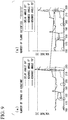
- the second coil 92 provided between the fifth and sixth segments is short-circuited by the brush 21.
- the tooth 12 corresponding to a U phase is present at a position that deviates by an electrical angle of 20° from a position where the advance angle is 0° (a position where the tooth 12 directly faces a magnetic pole).
- the first coil 91 provided between the first and second segments short-circuits.
- the tooth 12 corresponding to a U phase is present at a position where the advance angle is 0°, and rectification is performed at the position. Accordingly, a magnetomotive force vector of the advance angle 0° is generated on the tooth 12 corresponding to a U phase.
- the third coil 93 provided between the sixth and seventh segments short-circuits.
- the tooth 12 corresponding to a U phase is present at a position where the delay angle is 20°, and rectification is performed at the position. Accordingly, a magnetomotive force vector of the delay angle 20° is generated on the tooth 12 corresponding to a U phase.
- one coil is a 0°-advance-angle coil (a normal coil) that generates a magnetomotive force vector having no advance angle
- another coil is a 20°-advance-angle coil (an advance-angle coil) that generates a magnetomotive force vector of the advance angle 20°
- the other coil is a 20°-delay-angle coil (a delay-angle coil) that generates a magnetomotive force vector of the delay angle 20°.
- SEG The classification of the coils is shown in Table 1.
- "SEG” shown in Table 1 is the abbreviation for the segment. [Table 1] 0°-ADVANCE-ANGLE COIL WINDING WIRE CONNECTED BETWEEN FIRST AND SECOND SEG WINDING WIRE CONNECTED BETWEEN FOURTH AND FIFTH SEG WINDING WIRE CONNECTED BETWEEN SEVENTH AND EIGHTH SEG 20°-ADVANCE-ANGLE COIL WINDING WIRE CONNECTED BETWEEN FIFTH AND SIXTH SEG WINDING WIRE CONNECTED BETWEEN EIGHTH AND NINTH SEG WINDING WIRE CONNECTED BETWEEN SECOND AND THIRD SEG 20°-DELAY-ANGLE COIL WINDING WIRE CONNECTED BETWEEN SIXTH AND SEVENTH SEG WINDING WIRE CONNECTED BETWEEN NINTH AND FIRST SEG WINDING WIRE CONNECTED BETW
- T1 the number of turns (the number of turns of the winding wire 14) of the 20°-advance-angle coil
- T2 the number of turns of the 0°-advance-angle coil
- T3 the number of turns of the 20°-delay-angle coil
- condition (1) corresponds to the case of the low-speed brush 21a of which the position of the brush 21 is not advanced, and it is understood that the condition (1) needs to be changed according to the magnitude of the advance angle when the position of the low-speed brush 21a is advanced. Accordingly, the following conditions can be obtained.
- the advance angle ⁇ of the low-speed brush 21a is set as follows:
- an advance angle is set at the position of the high-speed brush 21b from the first, but the frequency of use of the advance angle is lower than that of an advance angle set at the position of the low-speed brush 21a. Accordingly, the above-mentioned conditions are set on the basis of the low-speed brush 21a.
- the number of turns of one coil among the three coils 91, 92, and 93 is set to be smaller than the number of turns of each of the other two coils. Accordingly, it is possible to reduce an influence of the deterioration of rectification performance that is caused by the discordance of the magnetomotive force vectors generated by the three coils 91, 92, and 93 wound on each tooth 12. Further, it is possible to lengthen the lifespan of the brushes by the improvement of rectification.
- the structure of the three coils 91, 92, and 93 is applied to the electric motor 2 of the motor 1 with a speed reducer that is used to drive windshield wipers of an automobile has been described in the above-mentioned embodiment.
- the invention is not limited to the embodiment, and the structure of the three coils 91, 92, and 93 can be applied to various electric motors in which three coils are formed on each tooth.
- the brush 21 includes three brushes, that is, the low-speed brush (the anode brush) 21a, the high-speed brush (the anode brush) 21b, and the common brush (the cathode brush) 21c has been described in the above-mentioned embodiment.
- the invention is not limited to the embodiment, and the structure of the three coils 91, 92, and 93 can also be applied to an electric motor in which an anode brush and a cathode brush are provided so as to make a pair.
- the electric motor since the number of turns of one coil is set to be smaller than the number of turns of each of the other two coils, it is possible to reduce an influence of the deterioration of rectification performance that is caused by the discordance of the magnetomotive force vectors generated by three coils. Further, it is possible to lengthen the lifespan of the brushes by the improvement of rectification.
Landscapes
- Engineering & Computer Science (AREA)
- Power Engineering (AREA)
- Dc Machiner (AREA)
- Windings For Motors And Generators (AREA)
Applications Claiming Priority (2)
| Application Number | Priority Date | Filing Date | Title |
|---|---|---|---|
| JP2014052304A JP6316032B2 (ja) | 2014-03-14 | 2014-03-14 | 電動モータ |
| PCT/JP2015/056494 WO2015137230A1 (ja) | 2014-03-14 | 2015-03-05 | 電動モータ |
Publications (3)
| Publication Number | Publication Date |
|---|---|
| EP3118979A1 true EP3118979A1 (de) | 2017-01-18 |
| EP3118979A4 EP3118979A4 (de) | 2017-12-06 |
| EP3118979B1 EP3118979B1 (de) | 2019-06-05 |
Family
ID=54071676
Family Applications (1)
| Application Number | Title | Priority Date | Filing Date |
|---|---|---|---|
| EP15761469.4A Active EP3118979B1 (de) | 2014-03-14 | 2015-03-05 | Elektromotor |
Country Status (5)
| Country | Link |
|---|---|
| US (1) | US10367401B2 (de) |
| EP (1) | EP3118979B1 (de) |
| JP (1) | JP6316032B2 (de) |
| CN (1) | CN106104990B (de) |
| WO (1) | WO2015137230A1 (de) |
Families Citing this family (2)
| Publication number | Priority date | Publication date | Assignee | Title |
|---|---|---|---|---|
| JP6928563B2 (ja) * | 2018-01-10 | 2021-09-01 | 株式会社ミツバ | モータ |
| JP7327947B2 (ja) * | 2019-02-25 | 2023-08-16 | ニデックプレシジョン株式会社 | モータ |
Family Cites Families (19)
| Publication number | Priority date | Publication date | Assignee | Title |
|---|---|---|---|---|
| US2509746A (en) * | 1949-03-29 | 1950-05-30 | Gen Electric | Rotor winding |
| JPS601824B2 (ja) * | 1977-12-22 | 1985-01-17 | 株式会社セコ−技研 | 重畳しない電機子巻線を備えた直流電動機 |
| JPS5499906A (en) * | 1978-01-23 | 1979-08-07 | Sekoh Giken Kk | Dc motor equipped with armature coil free from overlapping |
| US4447751A (en) * | 1981-11-12 | 1984-05-08 | Itsuki Ban | Direct current motor |
| US4583016A (en) * | 1983-06-28 | 1986-04-15 | Itsuki Ban | Direct current motor |
| JPS6198379U (de) * | 1984-11-30 | 1986-06-24 | ||
| US4847526A (en) * | 1985-07-11 | 1989-07-11 | Nippon Ferrofluidics Corporation | Variant-pole electric motor |
| US5044065A (en) * | 1990-05-24 | 1991-09-03 | Black & Decker Inc. | Coil winding armatures with parallel coils |
| JPH04265653A (ja) * | 1991-02-18 | 1992-09-21 | Mitsubishi Electric Corp | 直流電動機の電機子 |
| JP3047544B2 (ja) | 1991-08-30 | 2000-05-29 | 株式会社日立製作所 | 交流整流子電動機 |
| JPH11178300A (ja) * | 1997-12-15 | 1999-07-02 | Asmo Co Ltd | アーマチャ及びそのアーマチャを備えた回転電機 |
| JP2000341892A (ja) * | 1999-05-31 | 2000-12-08 | Asmo Co Ltd | 集中巻線モータの製造方法及び集中巻線モータ |
| JP3954504B2 (ja) * | 2003-01-23 | 2007-08-08 | アスモ株式会社 | モータ |
| JP4726627B2 (ja) * | 2003-10-08 | 2011-07-20 | 株式会社ミツバ | 回転電機におけるアーマチュアおよびその製造方法 |
| JP2007189870A (ja) * | 2006-01-16 | 2007-07-26 | Nidec Copal Corp | モータ |
| JP4528825B2 (ja) | 2007-12-21 | 2010-08-25 | 日立アプライアンス株式会社 | 自己始動型永久磁石同期電動機及びこれを用いた圧縮機 |
| JP5515426B2 (ja) * | 2009-05-28 | 2014-06-11 | 日本電産株式会社 | モータ |
| JP6091058B2 (ja) * | 2011-07-27 | 2017-03-08 | 株式会社ミツバ | 電動モータ |
| JP5847485B2 (ja) * | 2011-08-10 | 2016-01-20 | 株式会社ミツバ | 電動モータ |
-
2014
- 2014-03-14 JP JP2014052304A patent/JP6316032B2/ja active Active
-
2015
- 2015-03-05 US US15/112,537 patent/US10367401B2/en active Active
- 2015-03-05 CN CN201580012749.0A patent/CN106104990B/zh not_active Expired - Fee Related
- 2015-03-05 WO PCT/JP2015/056494 patent/WO2015137230A1/ja not_active Ceased
- 2015-03-05 EP EP15761469.4A patent/EP3118979B1/de active Active
Also Published As
| Publication number | Publication date |
|---|---|
| WO2015137230A1 (ja) | 2015-09-17 |
| CN106104990A (zh) | 2016-11-09 |
| JP6316032B2 (ja) | 2018-04-25 |
| US10367401B2 (en) | 2019-07-30 |
| EP3118979A4 (de) | 2017-12-06 |
| CN106104990B (zh) | 2018-11-23 |
| JP2015177637A (ja) | 2015-10-05 |
| US20160344273A1 (en) | 2016-11-24 |
| EP3118979B1 (de) | 2019-06-05 |
Similar Documents
| Publication | Publication Date | Title |
|---|---|---|
| US8436505B2 (en) | Electric motor and reduction motor | |
| US8378547B2 (en) | Electric motor | |
| US8188632B2 (en) | Miniature motor, and its manufacturing method | |
| CN103703661B (zh) | 电动机 | |
| US10734858B2 (en) | Electric motor | |
| EP3116101B1 (de) | Ankerkern, anker und elektromotor | |
| US20160190889A1 (en) | Brushed Direct Current Motor | |
| US9118223B2 (en) | Electric motor | |
| EP3118979B1 (de) | Elektromotor | |
| EP3739735B1 (de) | Motor | |
| JP2016135015A (ja) | コンミテータ、アーマチュア、及びブラシ付モータ | |
| JP2017017804A (ja) | 電動モータおよび減速機付モータ | |
| WO2019049607A1 (ja) | モータ |
Legal Events
| Date | Code | Title | Description |
|---|---|---|---|
| STAA | Information on the status of an ep patent application or granted ep patent |
Free format text: STATUS: THE INTERNATIONAL PUBLICATION HAS BEEN MADE |
|
| PUAI | Public reference made under article 153(3) epc to a published international application that has entered the european phase |
Free format text: ORIGINAL CODE: 0009012 |
|
| STAA | Information on the status of an ep patent application or granted ep patent |
Free format text: STATUS: REQUEST FOR EXAMINATION WAS MADE |
|
| 17P | Request for examination filed |
Effective date: 20160707 |
|
| AK | Designated contracting states |
Kind code of ref document: A1 Designated state(s): AL AT BE BG CH CY CZ DE DK EE ES FI FR GB GR HR HU IE IS IT LI LT LU LV MC MK MT NL NO PL PT RO RS SE SI SK SM TR |
|
| AX | Request for extension of the european patent |
Extension state: BA ME |
|
| DAV | Request for validation of the european patent (deleted) | ||
| DAX | Request for extension of the european patent (deleted) | ||
| A4 | Supplementary search report drawn up and despatched |
Effective date: 20171108 |
|
| RIC1 | Information provided on ipc code assigned before grant |
Ipc: H02K 23/32 20060101ALI20171102BHEP Ipc: H02K 23/38 20060101AFI20171102BHEP Ipc: H02K 7/116 20060101ALN20171102BHEP |
|
| RIC1 | Information provided on ipc code assigned before grant |
Ipc: H02K 23/38 20060101AFI20181115BHEP Ipc: H02K 23/26 20060101ALI20181115BHEP Ipc: H02K 23/32 20060101ALI20181115BHEP Ipc: H02K 7/116 20060101ALN20181115BHEP |
|
| RIC1 | Information provided on ipc code assigned before grant |
Ipc: H02K 7/116 20060101ALN20181116BHEP Ipc: H02K 23/32 20060101ALI20181116BHEP Ipc: H02K 23/26 20060101ALI20181116BHEP Ipc: H02K 23/38 20060101AFI20181116BHEP |
|
| GRAP | Despatch of communication of intention to grant a patent |
Free format text: ORIGINAL CODE: EPIDOSNIGR1 |
|
| STAA | Information on the status of an ep patent application or granted ep patent |
Free format text: STATUS: GRANT OF PATENT IS INTENDED |
|
| INTG | Intention to grant announced |
Effective date: 20190108 |
|
| GRAS | Grant fee paid |
Free format text: ORIGINAL CODE: EPIDOSNIGR3 |
|
| GRAA | (expected) grant |
Free format text: ORIGINAL CODE: 0009210 |
|
| STAA | Information on the status of an ep patent application or granted ep patent |
Free format text: STATUS: THE PATENT HAS BEEN GRANTED |
|
| RAP1 | Party data changed (applicant data changed or rights of an application transferred) |
Owner name: MITSUBA CORPORATION |
|
| AK | Designated contracting states |
Kind code of ref document: B1 Designated state(s): AL AT BE BG CH CY CZ DE DK EE ES FI FR GB GR HR HU IE IS IT LI LT LU LV MC MK MT NL NO PL PT RO RS SE SI SK SM TR |
|
| REG | Reference to a national code |
Ref country code: GB Ref legal event code: FG4D |
|
| REG | Reference to a national code |
Ref country code: CH Ref legal event code: EP |
|
| REG | Reference to a national code |
Ref country code: AT Ref legal event code: REF Ref document number: 1140990 Country of ref document: AT Kind code of ref document: T Effective date: 20190615 |
|
| REG | Reference to a national code |
Ref country code: IE Ref legal event code: FG4D |
|
| REG | Reference to a national code |
Ref country code: DE Ref legal event code: R096 Ref document number: 602015031426 Country of ref document: DE |
|
| REG | Reference to a national code |
Ref country code: NL Ref legal event code: MP Effective date: 20190605 |
|
| REG | Reference to a national code |
Ref country code: LT Ref legal event code: MG4D |
|
| PG25 | Lapsed in a contracting state [announced via postgrant information from national office to epo] |
Ref country code: SE Free format text: LAPSE BECAUSE OF FAILURE TO SUBMIT A TRANSLATION OF THE DESCRIPTION OR TO PAY THE FEE WITHIN THE PRESCRIBED TIME-LIMIT Effective date: 20190605 Ref country code: AL Free format text: LAPSE BECAUSE OF FAILURE TO SUBMIT A TRANSLATION OF THE DESCRIPTION OR TO PAY THE FEE WITHIN THE PRESCRIBED TIME-LIMIT Effective date: 20190605 Ref country code: ES Free format text: LAPSE BECAUSE OF FAILURE TO SUBMIT A TRANSLATION OF THE DESCRIPTION OR TO PAY THE FEE WITHIN THE PRESCRIBED TIME-LIMIT Effective date: 20190605 Ref country code: LT Free format text: LAPSE BECAUSE OF FAILURE TO SUBMIT A TRANSLATION OF THE DESCRIPTION OR TO PAY THE FEE WITHIN THE PRESCRIBED TIME-LIMIT Effective date: 20190605 Ref country code: FI Free format text: LAPSE BECAUSE OF FAILURE TO SUBMIT A TRANSLATION OF THE DESCRIPTION OR TO PAY THE FEE WITHIN THE PRESCRIBED TIME-LIMIT Effective date: 20190605 Ref country code: NO Free format text: LAPSE BECAUSE OF FAILURE TO SUBMIT A TRANSLATION OF THE DESCRIPTION OR TO PAY THE FEE WITHIN THE PRESCRIBED TIME-LIMIT Effective date: 20190905 Ref country code: HR Free format text: LAPSE BECAUSE OF FAILURE TO SUBMIT A TRANSLATION OF THE DESCRIPTION OR TO PAY THE FEE WITHIN THE PRESCRIBED TIME-LIMIT Effective date: 20190605 |
|
| PG25 | Lapsed in a contracting state [announced via postgrant information from national office to epo] |
Ref country code: GR Free format text: LAPSE BECAUSE OF FAILURE TO SUBMIT A TRANSLATION OF THE DESCRIPTION OR TO PAY THE FEE WITHIN THE PRESCRIBED TIME-LIMIT Effective date: 20190906 Ref country code: LV Free format text: LAPSE BECAUSE OF FAILURE TO SUBMIT A TRANSLATION OF THE DESCRIPTION OR TO PAY THE FEE WITHIN THE PRESCRIBED TIME-LIMIT Effective date: 20190605 Ref country code: RS Free format text: LAPSE BECAUSE OF FAILURE TO SUBMIT A TRANSLATION OF THE DESCRIPTION OR TO PAY THE FEE WITHIN THE PRESCRIBED TIME-LIMIT Effective date: 20190605 Ref country code: BG Free format text: LAPSE BECAUSE OF FAILURE TO SUBMIT A TRANSLATION OF THE DESCRIPTION OR TO PAY THE FEE WITHIN THE PRESCRIBED TIME-LIMIT Effective date: 20190905 |
|
| REG | Reference to a national code |
Ref country code: AT Ref legal event code: MK05 Ref document number: 1140990 Country of ref document: AT Kind code of ref document: T Effective date: 20190605 |
|
| PG25 | Lapsed in a contracting state [announced via postgrant information from national office to epo] |
Ref country code: AT Free format text: LAPSE BECAUSE OF FAILURE TO SUBMIT A TRANSLATION OF THE DESCRIPTION OR TO PAY THE FEE WITHIN THE PRESCRIBED TIME-LIMIT Effective date: 20190605 Ref country code: EE Free format text: LAPSE BECAUSE OF FAILURE TO SUBMIT A TRANSLATION OF THE DESCRIPTION OR TO PAY THE FEE WITHIN THE PRESCRIBED TIME-LIMIT Effective date: 20190605 Ref country code: PT Free format text: LAPSE BECAUSE OF FAILURE TO SUBMIT A TRANSLATION OF THE DESCRIPTION OR TO PAY THE FEE WITHIN THE PRESCRIBED TIME-LIMIT Effective date: 20191007 Ref country code: NL Free format text: LAPSE BECAUSE OF FAILURE TO SUBMIT A TRANSLATION OF THE DESCRIPTION OR TO PAY THE FEE WITHIN THE PRESCRIBED TIME-LIMIT Effective date: 20190605 Ref country code: CZ Free format text: LAPSE BECAUSE OF FAILURE TO SUBMIT A TRANSLATION OF THE DESCRIPTION OR TO PAY THE FEE WITHIN THE PRESCRIBED TIME-LIMIT Effective date: 20190605 Ref country code: RO Free format text: LAPSE BECAUSE OF FAILURE TO SUBMIT A TRANSLATION OF THE DESCRIPTION OR TO PAY THE FEE WITHIN THE PRESCRIBED TIME-LIMIT Effective date: 20190605 Ref country code: SK Free format text: LAPSE BECAUSE OF FAILURE TO SUBMIT A TRANSLATION OF THE DESCRIPTION OR TO PAY THE FEE WITHIN THE PRESCRIBED TIME-LIMIT Effective date: 20190605 |
|
| PG25 | Lapsed in a contracting state [announced via postgrant information from national office to epo] |
Ref country code: SM Free format text: LAPSE BECAUSE OF FAILURE TO SUBMIT A TRANSLATION OF THE DESCRIPTION OR TO PAY THE FEE WITHIN THE PRESCRIBED TIME-LIMIT Effective date: 20190605 Ref country code: IS Free format text: LAPSE BECAUSE OF FAILURE TO SUBMIT A TRANSLATION OF THE DESCRIPTION OR TO PAY THE FEE WITHIN THE PRESCRIBED TIME-LIMIT Effective date: 20191005 Ref country code: IT Free format text: LAPSE BECAUSE OF FAILURE TO SUBMIT A TRANSLATION OF THE DESCRIPTION OR TO PAY THE FEE WITHIN THE PRESCRIBED TIME-LIMIT Effective date: 20190605 |
|
| REG | Reference to a national code |
Ref country code: DE Ref legal event code: R097 Ref document number: 602015031426 Country of ref document: DE |
|
| PG25 | Lapsed in a contracting state [announced via postgrant information from national office to epo] |
Ref country code: TR Free format text: LAPSE BECAUSE OF FAILURE TO SUBMIT A TRANSLATION OF THE DESCRIPTION OR TO PAY THE FEE WITHIN THE PRESCRIBED TIME-LIMIT Effective date: 20190605 |
|
| PLBE | No opposition filed within time limit |
Free format text: ORIGINAL CODE: 0009261 |
|
| STAA | Information on the status of an ep patent application or granted ep patent |
Free format text: STATUS: NO OPPOSITION FILED WITHIN TIME LIMIT |
|
| PG25 | Lapsed in a contracting state [announced via postgrant information from national office to epo] |
Ref country code: DK Free format text: LAPSE BECAUSE OF FAILURE TO SUBMIT A TRANSLATION OF THE DESCRIPTION OR TO PAY THE FEE WITHIN THE PRESCRIBED TIME-LIMIT Effective date: 20190605 Ref country code: PL Free format text: LAPSE BECAUSE OF FAILURE TO SUBMIT A TRANSLATION OF THE DESCRIPTION OR TO PAY THE FEE WITHIN THE PRESCRIBED TIME-LIMIT Effective date: 20190605 |
|
| 26N | No opposition filed |
Effective date: 20200306 |
|
| PG25 | Lapsed in a contracting state [announced via postgrant information from national office to epo] |
Ref country code: SI Free format text: LAPSE BECAUSE OF FAILURE TO SUBMIT A TRANSLATION OF THE DESCRIPTION OR TO PAY THE FEE WITHIN THE PRESCRIBED TIME-LIMIT Effective date: 20190605 |
|
| PG25 | Lapsed in a contracting state [announced via postgrant information from national office to epo] |
Ref country code: MC Free format text: LAPSE BECAUSE OF FAILURE TO SUBMIT A TRANSLATION OF THE DESCRIPTION OR TO PAY THE FEE WITHIN THE PRESCRIBED TIME-LIMIT Effective date: 20190605 |
|
| REG | Reference to a national code |
Ref country code: CH Ref legal event code: PL |
|
| REG | Reference to a national code |
Ref country code: BE Ref legal event code: MM Effective date: 20200331 |
|
| PG25 | Lapsed in a contracting state [announced via postgrant information from national office to epo] |
Ref country code: LU Free format text: LAPSE BECAUSE OF NON-PAYMENT OF DUE FEES Effective date: 20200305 |
|
| PG25 | Lapsed in a contracting state [announced via postgrant information from national office to epo] |
Ref country code: CH Free format text: LAPSE BECAUSE OF NON-PAYMENT OF DUE FEES Effective date: 20200331 Ref country code: LI Free format text: LAPSE BECAUSE OF NON-PAYMENT OF DUE FEES Effective date: 20200331 Ref country code: IE Free format text: LAPSE BECAUSE OF NON-PAYMENT OF DUE FEES Effective date: 20200305 |
|
| PG25 | Lapsed in a contracting state [announced via postgrant information from national office to epo] |
Ref country code: BE Free format text: LAPSE BECAUSE OF NON-PAYMENT OF DUE FEES Effective date: 20200331 |
|
| GBPC | Gb: european patent ceased through non-payment of renewal fee |
Effective date: 20200305 |
|
| PG25 | Lapsed in a contracting state [announced via postgrant information from national office to epo] |
Ref country code: GB Free format text: LAPSE BECAUSE OF NON-PAYMENT OF DUE FEES Effective date: 20200305 |
|
| PG25 | Lapsed in a contracting state [announced via postgrant information from national office to epo] |
Ref country code: MT Free format text: LAPSE BECAUSE OF FAILURE TO SUBMIT A TRANSLATION OF THE DESCRIPTION OR TO PAY THE FEE WITHIN THE PRESCRIBED TIME-LIMIT Effective date: 20190605 Ref country code: CY Free format text: LAPSE BECAUSE OF FAILURE TO SUBMIT A TRANSLATION OF THE DESCRIPTION OR TO PAY THE FEE WITHIN THE PRESCRIBED TIME-LIMIT Effective date: 20190605 |
|
| PG25 | Lapsed in a contracting state [announced via postgrant information from national office to epo] |
Ref country code: MK Free format text: LAPSE BECAUSE OF FAILURE TO SUBMIT A TRANSLATION OF THE DESCRIPTION OR TO PAY THE FEE WITHIN THE PRESCRIBED TIME-LIMIT Effective date: 20190605 |
|
| PGFP | Annual fee paid to national office [announced via postgrant information from national office to epo] |
Ref country code: FR Payment date: 20230208 Year of fee payment: 9 |
|
| PGFP | Annual fee paid to national office [announced via postgrant information from national office to epo] |
Ref country code: DE Payment date: 20230131 Year of fee payment: 9 |
|
| REG | Reference to a national code |
Ref country code: DE Ref legal event code: R119 Ref document number: 602015031426 Country of ref document: DE |
|
| PG25 | Lapsed in a contracting state [announced via postgrant information from national office to epo] |
Ref country code: DE Free format text: LAPSE BECAUSE OF NON-PAYMENT OF DUE FEES Effective date: 20241001 |
|
| PG25 | Lapsed in a contracting state [announced via postgrant information from national office to epo] |
Ref country code: FR Free format text: LAPSE BECAUSE OF NON-PAYMENT OF DUE FEES Effective date: 20240331 |
|
| PG25 | Lapsed in a contracting state [announced via postgrant information from national office to epo] |
Ref country code: FR Free format text: LAPSE BECAUSE OF NON-PAYMENT OF DUE FEES Effective date: 20240331 Ref country code: DE Free format text: LAPSE BECAUSE OF NON-PAYMENT OF DUE FEES Effective date: 20241001 |