EP3119078B1 - Dispositif de capture d'image et son procédé de mise au point automatique - Google Patents
Dispositif de capture d'image et son procédé de mise au point automatique Download PDFInfo
- Publication number
- EP3119078B1 EP3119078B1 EP16178958.1A EP16178958A EP3119078B1 EP 3119078 B1 EP3119078 B1 EP 3119078B1 EP 16178958 A EP16178958 A EP 16178958A EP 3119078 B1 EP3119078 B1 EP 3119078B1
- Authority
- EP
- European Patent Office
- Prior art keywords
- auto
- data
- mode
- image sensor
- search
- Prior art date
- Legal status (The legal status is an assumption and is not a legal conclusion. Google has not performed a legal analysis and makes no representation as to the accuracy of the status listed.)
- Active
Links
Images




Classifications
-
- G—PHYSICS
- G03—PHOTOGRAPHY; CINEMATOGRAPHY; ANALOGOUS TECHNIQUES USING WAVES OTHER THAN OPTICAL WAVES; ELECTROGRAPHY; HOLOGRAPHY
- G03B—APPARATUS OR ARRANGEMENTS FOR TAKING PHOTOGRAPHS OR FOR PROJECTING OR VIEWING THEM; APPARATUS OR ARRANGEMENTS EMPLOYING ANALOGOUS TECHNIQUES USING WAVES OTHER THAN OPTICAL WAVES; ACCESSORIES THEREFOR
- G03B13/00—Viewfinders; Focusing aids for cameras; Means for focusing for cameras; Autofocus systems for cameras
- G03B13/18—Focusing aids
- G03B13/20—Rangefinders coupled with focusing arrangements, e.g. adjustment of rangefinder automatically focusing camera
-
- G—PHYSICS
- G03—PHOTOGRAPHY; CINEMATOGRAPHY; ANALOGOUS TECHNIQUES USING WAVES OTHER THAN OPTICAL WAVES; ELECTROGRAPHY; HOLOGRAPHY
- G03B—APPARATUS OR ARRANGEMENTS FOR TAKING PHOTOGRAPHS OR FOR PROJECTING OR VIEWING THEM; APPARATUS OR ARRANGEMENTS EMPLOYING ANALOGOUS TECHNIQUES USING WAVES OTHER THAN OPTICAL WAVES; ACCESSORIES THEREFOR
- G03B13/00—Viewfinders; Focusing aids for cameras; Means for focusing for cameras; Autofocus systems for cameras
- G03B13/32—Means for focusing
- G03B13/34—Power focusing
- G03B13/36—Autofocus systems
-
- H—ELECTRICITY
- H04—ELECTRIC COMMUNICATION TECHNIQUE
- H04N—PICTORIAL COMMUNICATION, e.g. TELEVISION
- H04N13/00—Stereoscopic video systems; Multi-view video systems; Details thereof
- H04N13/20—Image signal generators
- H04N13/204—Image signal generators using stereoscopic image cameras
- H04N13/239—Image signal generators using stereoscopic image cameras using two two-dimensional [2D] image sensors having a relative position equal to or related to the interocular distance
-
- H—ELECTRICITY
- H04—ELECTRIC COMMUNICATION TECHNIQUE
- H04N—PICTORIAL COMMUNICATION, e.g. TELEVISION
- H04N13/00—Stereoscopic video systems; Multi-view video systems; Details thereof
- H04N13/20—Image signal generators
- H04N13/271—Image signal generators wherein the generated image signals comprise depth maps or disparity maps
-
- H—ELECTRICITY
- H04—ELECTRIC COMMUNICATION TECHNIQUE
- H04N—PICTORIAL COMMUNICATION, e.g. TELEVISION
- H04N23/00—Cameras or camera modules comprising electronic image sensors; Control thereof
- H04N23/60—Control of cameras or camera modules
- H04N23/667—Camera operation mode switching, e.g. between still and video, sport and normal or high- and low-resolution modes
-
- H—ELECTRICITY
- H04—ELECTRIC COMMUNICATION TECHNIQUE
- H04N—PICTORIAL COMMUNICATION, e.g. TELEVISION
- H04N23/00—Cameras or camera modules comprising electronic image sensors; Control thereof
- H04N23/60—Control of cameras or camera modules
- H04N23/67—Focus control based on electronic image sensor signals
- H04N23/672—Focus control based on electronic image sensor signals based on the phase difference signals
-
- H—ELECTRICITY
- H04—ELECTRIC COMMUNICATION TECHNIQUE
- H04N—PICTORIAL COMMUNICATION, e.g. TELEVISION
- H04N23/00—Cameras or camera modules comprising electronic image sensors; Control thereof
- H04N23/60—Control of cameras or camera modules
- H04N23/67—Focus control based on electronic image sensor signals
- H04N23/673—Focus control based on electronic image sensor signals based on contrast or high frequency components of image signals, e.g. hill climbing method
Definitions
- the disclosure relates to is directed to an image capturing device and an auto-focus (AF) method thereof.
- AF auto-focus
- the digital camera could be embedded in handheld electronic devices such as cellular phones, smart phones, tablet computers, personal digital assistants and so forth.
- handheld electronic devices such as cellular phones, smart phones, tablet computers, personal digital assistants and so forth.
- the diminutive nature of such camera allows the camera to become a convenient and popular additional feature of portable consumer electronic devices.
- the portability of such electronic devices may have prevented many more sophisticated uses or structures to be included for such cameras.
- fixed focal length lenses and small sensors would typically be used for such cameras since an optical zoom lens may be too heavy and require more physical depths than the body of the handheld electronic device would permit, and yet the speed of an auto-focus procedure is highly dependent on the maximum aperture offered by the lens. Therefore, there is a need for an effective auto-focus method for such handheld electronic device.
- This object can be achieved by the features as defined by the independent claims. Further enhancements are characterised by the dependent claims.
- an auto-focus method of an image capturing device including a distance sensor and an image sensor having a lens and a sensing array is proposed.
- the method includes the steps according to claim 1.
- an image capturing device according to claim 10 is proposed.
- a distance sensor data is obtained from the distance sensor
- disparity data is obtained according to the sensing arrays of the image sensors.
- the lenses are controlled to perform a coarse search within a focusing range by switching between a distance sensor auto-focus (DSAF) mode and a disparity detection auto-focus (DDAF) mode based on the DS data and the DD data so as to determine a fine-search range.
- the lenses are further controlled to perform a fine search within the fine-search range in a CDAF mode so as to determine an optimal focusing lens position.
- the lenses are controlled to move to the optimal focusing lens position.
- the collaboration of the two auto-focus modes based on the data obtained from the distance sensor and the sensing array would enable the lens to scan through the entire focusing range with larger steps.
- the lens is controlled to search for the optimal focusing lens position with smaller steps.
- the proposed hybrid auto-focus method is used for efficiently speed up the auto-focus procedure so as to greatly enhance user experience.
- FIG. 1 illustrates a schematic diagram of an image capturing device in accordance with one of the exemplary embodiments of the disclosure. All components of the image capturing device and their configurations are first introduced in FIG. 1 . The functionalities of the components are disclosed in more detail in conjunction with FIG. 3 .
- the image capturing device 100 could be a digital camera, a digital camcorder, a digital single lens reflex camera or other devices provided with an image capturing feature such as a smart phone, a tablet computer, a personal digital assistant, and so on.
- the image capturing device 100 may include at least one image sensor 10, a distance sensor 20, a memory 30, and a processor 40, where the image sensor 10, the distance sensor 20, and the memory 30 are respectively coupled to the processor 40.
- only one image sensor will be illustrated for simplicity.
- the image sensor 10 would include a lens 12 and a sensing array 14.
- the sensing array 14 may be charge-coupled-device (CCD) elements, complementary metal-oxide semiconductor (CMOS) elements, and yet the disclosure is not limited herein.
- An image captured by the lens 12 would be imaged onto the sensing array 14.
- the image formed on the sensing array 14 would be converted to digital signals, and the digital signals would be output to the processor 40.
- CCD charge-coupled-device
- CMOS complementary metal-oxide semiconductor
- the sensing array 14 include a plurality of pixels arranged in an array.
- some pixels are configured as phase detection pixels, where each of the phase detection pixels is partially-shielded for phase detection during an auto-focus process.
- the pixels of the sensing array 14 would be arranged in Bayer pattern with R, G, and B pixels.
- some of the G pixels are partially replaced by phase detection pixels including left-shielded pixels PDL and right-shielded pixels PDR.
- phase difference An offset between each of the left-shielded pixels PDL and its corresponding right-shielded pixel PDR is referred to as "phase difference", where the phase difference is proportional to the distance from an in-focus position (also known as “defocus distance”).
- the distance sensor 20 may be infrared, ultrasonic, or laser sensors for measuring the distance between a target object and the image sensor 10.
- the memory 30 may be one or a combination of a stationary or mobile random access memory (RAM), a read-only memory (ROM), a flash memory, a hard drive or other various forms of non-transitory, volatile, and non-volatile memories.
- RAM random access memory
- ROM read-only memory
- flash memory a hard drive or other various forms of non-transitory, volatile, and non-volatile memories.
- the processor 40 may be, for example, a central processor (CPU) or other programmable devices for general purpose or special purpose such as a microprocessor, a digital signal processor (DSP), a graphical processor (GPU), a programmable controller, an application specific integrated circuit (ASIC), a programmable logic device (PLD) or other similar or a combination of aforementioned components.
- CPU central processor
- DSP digital signal processor
- GPU graphical processor
- ASIC application specific integrated circuit
- PLD programmable logic device
- FIG. 3 illustrates a flowchart of an auto-focus method in accordance with one of the exemplary embodiments of the disclosure.
- the steps of FIG. 3 could be implemented by the proposed image capturing device 100 as illustrated in FIG. 1 .
- an infrared sensor would be the distance sensor 20 hereinafter.
- the processor 40 obtains distance sensor data (DS data) from the distance sensor 20 (Step S302) and phase detection data (PD data) from the image sensor 10 (Step S304).
- DS data distance sensor data
- PD data phase detection data
- the processor 40 would control the distance sensor 20 to emit infrared light toward a target object in the target scene and receive the reflected infrared light from the target object and thereby obtain the DS data.
- the DS data may include a measured distance between the distance sensor 20 and the target object (referred to as “an object distance” hereinafter) as well as a surface reflectance of the target object (referred to as “an object reflectance” hereinafter).
- the processor 40 would obtain the PD data corresponding to the phase detection pixels of the sensing array 14.
- the PD data may include a phase difference value (PD value) and a confidence level.
- the PD value describes an offset between a left-shielded pixel and its corresponding right-shielded pixels, and the confidence level is a reference index in proportion to the number of easy-to-detect phase difference vertical edge inside an auto-focus window.
- the DS data and the PD data are used as auxiliary information for speeding up the entire auto-focus process. That is, the processor 40 controls the lens 12 to perform a coarse search within a focusing range by switching the image sensor 10 between a distance sensor auto-focus (DSAF) mode and a phase detection auto-focus (PDAF) mode based on the DS data and the PD data so as to determine a fine-search range (Step S306).
- the DSAF mode corresponding to the distance sensor 20 may work efficiently and provide precise measurement for a short-distance target object.
- the PDAF mode corresponding to the phase detection pixels of the image sensor 10 may be relatively suitable for a long-distance target object since the PD value between the phase detection pixels are more comparable.
- the collaboration of the two auto-focus modes would enable the lens 12 to scan through the entire focusing range with large steps to first determine the coarse-search focusing position and then identify the fine-search range in which an optimal-focusing lens position is located according to the coarse-search focusing position.
- the processor 40 After the fine-search range is determined, the processor 40 would control the lens 12 to perform a fine search within the fine-search range in a contrast detection auto-focus (CDAF) mode so as to determine an optimal focusing lens position (Step S308). Next, the processor 40 would control the lens 12 to move to the optimal focusing lens position (Step S310), and the AF process is then completed.
- the optimal focusing lens position represents a lens position where the contrast of a frame appears to be the peak or the maximum value.
- CDAF is relatively slower than PDAF or DSAF since multiple frame readings would be necessary to determine the optimal focusing lens position and yet provides a more precise auto-focus result.
- the proposed method could reduce the entire auto-focus process to 200ms or so.
- the following embodiments are included to demonstrate the proposed auto-focus method for capturing a still image and a video stream with more particularity.
- FIG. 4 illustrates a flowchart of an auto-focus method upon capturing a still image in accordance with one of the exemplary embodiments of the disclosure.
- the method in the present exemplary embodiment may also be implemented by the electronic device 100 in FIG. 1 .
- the processor 40 obtains DS data by using the distance sensor 20 (Step S402) and PD data by using the image sensor 10 (Step S404).
- Detailed steps for obtaining the DS data and the PD data may refer to the related description in Step S302 and Step S304 as explained in the previous paragraphs and would not be repeated herein.
- the processor 40 determines whether an auto-focus window is located at the center of a target scene (Step S406), where the auto-focus window is usually a rectangle. This can be done by determining whether the coordinates of the auto-focus window are located at the center or other positions at the corners of the target scene.
- the processor 40 determines that the auto-focus window is located at the center of the target scene, there would be a high possibility that the target object is located within a short distance from the image sensor 10.
- the processor 40 would switch the image sensor 10 to the DSAF mode and then decide whether to start performing a coarse search in a focusing range by determining whether the DS data satisfies a DSAF condition (Step S408).
- the determination could be based on an object reflectance and an object distance of the target object.
- the processor 40 may determine whether the object reflectance exceeds a rate threshold given that the object distance is within a detecting range of the distance sensor 20.
- the processor 40 may determine whether the object distance is less than a distance threshold.
- the DSAF condition may be set as follows:
- Step S410 When the determination of Step S408 is YES, it represents that the object distance is short or the object reflectance is high enough for the distance sensor auto-focus mode. Under such circumstance, the processor 40 would start performing the coarse search in the focusing range by controlling the lens 12 to move to a coarse-search focusing position based on a distance-DAC relationship stored in the memory 30 (Step S410).
- the distance-DAC relationship includes different code values (referred to as DAC values), where each of the DAC values is an indicative of a signal that must be applied to move the lens to a position corresponding to the object distance for auto-focus adjustment.
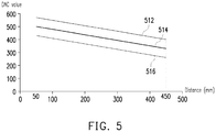
- the distance-DAC relationship may be constructed based on Table 1, where the distance-DAC relationships corresponding to object distances of 100mm and 400mm with respect to different lens postures are given. Table 1 Lens Posture Upward Forward Downward 400 (mm) 400 420 350 280 Macro(mm) 100 548 478 408 mm/DAC -0.42667 -0.42667 -0.42667
- the distance-DAC relationship corresponding to other object distances may be acquired by an interpolation method as illustrated in FIG. 5 , where lines 512, 514, and 516 respectively represents the distance-DAC relationships with respect to an upward posture, a forward posture, and a downward posture of the lens 12.
- the processor 40 would switch the image sensor 10 to the PDAF mode for auto-focus accuracy verification based on the PD data. The description of which will be provided later on.
- Step S406 when the processor 40 determines that the auto-focus window is not located at the center of the target scene in Step S406, the processor 40 would directly switch the image sensor 10 to the PDAF mode and perform Step S412.
- Step S412 When the determination of Step S412 is YES, it represents that the PD data is valid for the PDAF mode. Under such circumstance, the processor 40 would obtain a predicted DAC value by inputting the PD value into a PD value-DAC relationship stored in the memory 30 (Step S414) and then control the lens 12 to move to a coarse-search focusing position based on the predicted DAC value and the current DAC value (Step S416).
- the PD value-DAC relationship includes different predicted DAC values, where each of the predicted DAC values corresponding to a PD value for auto-focus adjustment. In other words, the summation of the current DAC value and the predicted DAC value corresponds to the coarse-search focusing position.
- Step S410 the processor 40 would verify auto-focus accuracy based on the PD data (Step S418) and the number of PD count (Step S419), where the PD count is the number of iterations where Step S414 and Step S416 are performed.
- the processor 40 may return to Step S414.
- the processor 40 may perform auto-focus accuracy verification and the number of PD count based on the following expression: PD value ⁇ 1 PD pixel & & PD count ⁇ 3
- Step S420 the processor 40 may set the search range from 500mm to infinity.
- Step S412 the determination of Step S412 is NO, it represents that the PD data is invalid for the PDAF mode, the processor 40 would also perform Step S420 to switch the image sensor 10 to the CDAF mode.
- the processor 40 would set a fine search range for the CDAF mode based on ambient light.
- the processor 40 would first determine whether an ISO/gain value is less than or equal to an ISO threshold (e.g. 800) (Step S422). If the determination is YES (i.e. the ambient light is sufficient), the processor 40 would set a smaller fine search range for the CDAF mode (Step S424).
- the fine search range may be 1 PD pixel DCC step with respect to the coarse-search focusing position. If the determination is NO (i.e.
- the processor 40 would set a larger fine search range for the CDAF mode (Step S426) so as to compensate the inaccuracy of PDAF due to a large analog gain.
- the fine search range may be set based on Table 2 as illustrated below: Table 2 CDAF ISO800 ISO1600 ISO3200 AF_Range ⁇ 16 ⁇ 32 ⁇ 64 A F_Ste p 4 8 12
- Step S420 After the fine search range for the CDAF mode is set, either from Step S420, Step S424, or Step S426, the processor 40 would perform a fine search within the fine-search range and control the lens 12 to move to an optimal focusing lens position (Step S428), and the auto-focus process is then completed.
- FIG. 6 illustrates a flowchart of an auto-focus method upon capturing a video stream in accordance with one of the exemplary embodiments of the disclosure.
- the method in the present exemplary embodiment may also be implemented by the electronic device 100 in FIG. 1 .
- the processor 40 obtains DS data by using the distance sensor 20 (Step S602) and PD data by using the image sensor 10 (Step S604). Next, the processor 40 determines whether an auto-focus window is located at the center of a target scene (Step S606).
- the processor 40 determines that the auto-focus window is located at the center of the target scene, the processor 40 would switch the image sensor 10 to the DSAF mode and then decide whether to start performing a coarse search in a focusing range by determining whether the DS data satisfies a DSAF condition (Step S608).
- Step S608 When the determination of Step S608 is YES, the processor 40 would start performing the coarse search in the focusing range by controlling the lens 12 to move to a coarse-search focusing position based on a distance-DAC relationship stored in the memory 30 (Step S610). Once the lens 12 is moved to the coarse-search focusing position, the processor 40 would switch the image sensor 10 to the PDAF mode for auto-focus accuracy verification.
- Step S608 when the determination of Step S608 is NO, the processor 40 would switch the image sensor 10 to the PDAF mode and decide whether to start performing the coarse search in the focusing range by determining whether the PD data satisfies a PDAF condition (Step S612). It should be noted that, when the processor 40 determines that the auto-focus window is not located at the center of the target scene in Step S606, the processor 40 would directly switch the image sensor 10 to the PDAF mode and perform Step S612.
- Step S612 When the determination of Step S612 is YES, the processor 40 would obtain a predicted DAC value by inputting the PD value into a PD value-DAC relationship stored in the memory 30 (Step S614) and then control the lens 12 to move to a coarse-search focusing position based on the predicted DAC value and the current DAC value (Step S616). Once the lens 12 is moved to the coarse-search focusing position, either from Step S610 or from Step S616, the processor 40 would verify auto-focus accuracy based on the PD data (Step S618) and the number of PD count (Step S619). When the PD data fails the auto-focus accuracy verification and yet the PD count does not exceed the threshold number, the processor 40 may return to Step S614.
- Step S620 When both of the auto-focus accuracy verification fails in Step S618 and Step S619, the processor 40 would switch the image sensor 10 to the CDAF mode by first setting a fine-search range for the CDAF mode (Step S620). On the other hand, when the verification successes, the processor 40 would set a fine search range for the CDAF mode based on ambient light. The processor 40 would first determine whether an ISO/gain value is less than or equal to an ISO threshold (Step S622). If the determination is NO (i.e. the ambient light is insufficient), the processor 40 would set a larger fine search range for the CDAF mode (Step S626) so as to compensate the inaccuracy of PDAF due to a large analog gain.
- Step S602-S622 and S626 may refer to the related description in S402-S422 and S426 as explained in the previous paragraphs and would not be repeated herein.
- the processor 40 prior to a fine search, the processor 40 would determine whether to control the lens 12 to move forward or backward by determining whether the PD value is positive or negative (Step S623). In the case of capturing a near object, such that the PD value is positive, the processor 40 would control the lens 12 to start moving forward to a macro distance (Step S625). In the case of capturing a far object, such that the PD value is negative, the processor 40 would control the lens 12 to start moving backward to an infinity distance (Step S627).
- Step S628 the processor 40 controls the lens 12 to start moving forward or backward
- the processor 40 would perform the fine search within the fine-search range and control the lens 12 to move to an optimal focusing lens position according to the moving direction (Step S628), and the auto-focus process is then completed. It should be noted that, when the processor 40 switches the image sensor 10 to the CDAF mode in Step S620, it would directly perform Step S628.
- FIG. 7 illustrates a schematic diagram of another image capturing device in accordance with one of the exemplary embodiments of the disclosure.
- a mobile electronic device 700 would include an image sensor 710a having a lens 712a and a sensing array 714a, an image sensor 710b having a lens 712b and a sensing array 714b, a distance sensor 720, a memory 730, and a processor 740, where the image sensors 710a and 710b, the distance sensor 720, and the memory 730 are respectively coupled to the processor 740, wherein similar components to FIG. 1 are designated with similar numbers having a "7" prefix.
- phase detection pixels are not necessarily to be included in the sensing arrays 714a and 714b.
- the processor 40 would use the disparity between two images concurrently captured by the two image sensors 710a and 710b in conjunction with DS data obtained from the distance sensor 10 as auxiliary information for speeding up the entire auto-focus process.
- the auto-focus process would be similar to the auto-focus method illustrated in FIG. 3 , FIG. 4 , and FIG. 6 .
- the only differences are that the PD data, the PDAF condition, and PD value-DAC relationship would be replaced by disparity data, disparity data verification, and disparity-DAC relationship.
- FIG. 8 illustrates a flowchart of an auto-focus method in accordance with one of the exemplary embodiments of the disclosure.
- the processor 40 obtains DS data from the distance sensor 720 (Step S802) and disparity data (DD data) according to the image sensors 710a and 710b (Step S804).
- the processor 740 would control the distance sensor 720 to emit infrared light toward a target object in the target scene and receive the reflected infrared light from the target object and thereby obtain the DS data.
- the DS data may include an object distance as well as an object reflectance.
- the processor 740 would obtain the DD data corresponding to the disparity between the image data generated by the sensing array 714a and 714b.
- the DS data and the DD data are used as auxiliary information for speeding up the entire auto-focus process. That is, the processor 740 controls the lenses 712a and 712b to perform a coarse search within a focusing range by switching the image sensors 710a and 710b between a DSAF mode and a disparity detection auto-focus (DDAF) mode based on the DS data and the DD data so as to determine a fine-search range (Step S806).
- the DSAF mode corresponding to the distance sensor 720 may work efficiently and provide precise measurement for a short-distance target object.
- the DDAF mode corresponding to the disparity between the two images generated by the two image sensors 710a and 710b may be relatively suitable for a long-distance target object.
- the collaboration of the two auto-focus modes would enable the lenses 712a and 712b to scan through the entire focusing range with large steps to first determine the coarse-search focusing position and then identify the fine-search range in which an optimal-focusing lens position is located according to the coarse-search focusing position.
- the processor 740 would control the lenses 712a and 712b to perform a fine search within the fine-search range in a CDAF mode so as to determine an optimal focusing lens position (Step S808).
- the processor 740 would control the lenses 712a and 712b to move to the optimal focusing lens position (Step S810), and the auto-focus process is then completed.
- the collaboration of the two auto-focus modes based on the data obtained from the image sensor and the distance sensor would enable the lens to scan through the entire focusing range with larger steps.
- the lens is controlled to search for the optimal focusing lens position with smaller steps.
- the proposed hybrid auto-focus method is used for efficiently speed up the auto-focus procedure so as to greatly enhance user experience.
Landscapes
- Engineering & Computer Science (AREA)
- Multimedia (AREA)
- Signal Processing (AREA)
- Physics & Mathematics (AREA)
- General Physics & Mathematics (AREA)
- Studio Devices (AREA)
- Automatic Focus Adjustment (AREA)
Claims (12)
- Un procédé de mise au point automatique, conçu pour un dispositif de capture d'image comprenant un capteur de distance (20) qui est un capteur infrarouge, ultrasonore ou laser pour la mesure d'une distance entre un objet cible et un capteur d'image (10), et le capteur d'image ayant une lentille (12) et une matrice de captation (14), le procédé comprenant les étapes consécutives suivantes :l'obtention de données de capteur de distance, données DS, et de données de détection de phase, données PD, provenant respectivement du capteur de distance (20) et de la matrice de captation (14) ;la détermination quant à savoir si une fenêtre de mise au point automatique est située au niveau d'un centre d'une scène cible comprenant l'objet cible ;dans la négative, la commutation du capteur d'image (10) vers un mode de mise au point automatique par détection de phase, PDAF, sur la base des données PD ;dans l'affirmative, la commutation du capteur d'image (10) vers un mode de mise au point automatique par capteur de distance, DSAF, sur la base des données DS ;la commande de la lentille (12) pour exécuter une recherche grossière dans une plage de mise au point après ladite commutation du capteur d'image (10) entre le mode DSAF et le mode PDAF pour déterminer une plage de recherche fine ;la commande de la lentille (12) pour exécuter une recherche fine à l'intérieur de la plage de recherche fine dans un mode de mise au point automatique par détection de contraste, CDAF, pour déterminer une position de lentille de mise au point optimale ; etla commande de la lentille (12) pour se déplacer jusqu'à la position de lentille de mise au point optimale.
- Le procédé de mise au point automatique selon la revendication 1, dans lequel lorsque le capteur d'image (10) est commuté vers le mode DSAF et avant que la plage de recherche fine soit déterminée, l'étape de commande de la lentille (12) pour exécuter la recherche grossière dans la plage de mise au point par commutation du capteur d'image (10) entre le mode DSAF et le mode PDAF sur la base des données DS et des données PD comprend :la détermination quant à savoir si les données DS satisfont à une condition DASF, la condition DASF étant associée à une réflexion d'objet et à une distance d'objet de l'objet cible ;dans la négative, la commutation du capteur d'image (10) vers le mode PDAF ; etdans l'affirmative, l'exécution d'un processus DSAF par commande de la lentille pour se déplacer jusqu'à la position de mise au point par recherche grossière sur la base d'une relation distance-convertisseur numérique-analogique, distance-DAC, et la commutation du capteur d'image vers le mode PDAF.
- Le procédé de mise au point automatique selon l'une quelconque des revendications précédentes, dans lequel lorsque le capteur d'image est commuté vers le mode PDAF et avant que la plage de recherche fine soit déterminée, l'étape de commande de la lentille pour exécuter la recherche grossière dans la plage de mise au point par commutation du capteur d'image entre le mode DSAF et le mode PDAF sur la base des données DS et des données PD comprend :la détermination quant à savoir si les données PD satisfont à une condition PDAF, la condition PDAF étant associée à une valeur PD et à un niveau de confiance des données PD ;dans la négative, la commutation du capteur d'image vers le mode CDAF ; etdans l'affirmative, l'exécution d'un processus PDAF par obtention d'une valeur de convertisseur numérique-analogique, DAC, prédite sur la base d'une relation valeur PD-DAC et la commande de la lentille pour se déplacer jusqu'à la position de mise au point par recherche grossière sur la base de la valeur DAC prédite et d'une valeur DAC courante.
- Le procédé de mise au point automatique selon l'une quelconque des revendications précédentes, dans lequel avant que la plage de recherche fine soit déterminée, l'étape de commande de la lentille pour exécuter la recherche grossière dans la plage de mise au point par commutation du capteur d'image entre le mode DSAF et le mode PDAF sur la base des données DS et des données PD, le procédé de mise au point automatique comprend en outre les étapes suivantes :l'obtention de données PD mises à jour provenant de la matrice de captation ;la vérification d'une précision de mise au point automatique sur la base des données PD mises à jour ; ets'il est vérifié que la précision de mise au point automatique est précise, le réglage de commutation du capteur d'image vers le mode CDAF pour déterminer la plage de recherche fine.
- Le procédé de mise au point automatique selon la revendication 4, dans lequel lorsqu'il est vérifié que la précision de mise au point automatique est imprécise, le procédé de mise au point automatique comprend en outre les étapes suivantes :la détermination quant à savoir si un compte PD courant est inférieur à un seuil de compte PD, le compte PD courant étant le nombre de fois que le processus PDAF a été exécuté ;dans l'affirmative, l'incrémentation du compte PD courant d'une unité et la réexécution du processus PDAF ;dans la négative, la commutation du capteur d'image vers le mode CDAF.
- Le procédé de mise au point automatique selon l'une quelconque des revendications précédentes, dans lequel lorsqu'une position de mise au point par recherche grossière existe dans la plage de mise au point, l'étape de détermination de la plage de recherche fine comprend :
le réglage de la plage de recherche fine par rapport à la position de mise au point par recherche grossière. - Le procédé de mise au point automatique selon la revendication 6, dans lequel l'étape de détermination de la plage de recherche fine comprend en outre les étapes suivantes :la détermination quant à savoir si une valeur ISO/gain est inférieure ou égale à un seuil ISO ;dans l'affirmative, la décrémentation de la plage de recherche fine ; etdans la négative, l'incrémentation de la plage de recherche fine.
- Le procédé de mise au point automatique selon l'une quelconque des revendications précédentes, dans lequel lorsque la position de mise au point par recherche grossière n'existe pas dans la plage de mise au point, l'étape de détermination de la plage de recherche fine comprend :
le réglage de la plage de mise au point comme plage de recherche fine. - Le procédé de mise au point automatique selon l'une quelconque des revendications 6 à 8, dans lequel pendant que le dispositif de capture d'image est en train de capturer un flux vidéo, après que la plage de recherche fine a été réglée, le procédé de mise au point automatique comprend en outre les étapes suivantes :l'obtention de données PD mises à jour provenant de la matrice de captation et la détermination quant à savoir si les données PD mises à jour sont supérieures à zéro ;dans l'affirmative, la commande de la lentille pour se déplacer vers l'avant ; etdans la négative, la commande de la lentille pour se déplacer vers l'arrière.
- Un dispositif de capture d'image conçu pour exécuter un procédé de mise au point automatique selon la revendication 1, le dispositif de capture d'image comprend :un capteur de distance (20), configuré pour mesurer une distance entre un objet cible etun capteur d'image (10), et le capteur d'image (10) comprenant une lentille (12) et une matrice de captation (14), la matrice de captation (14) comprenant une pluralité de pixels, et une partie des pixels étant configurés comme pixels de détection de phase partiellement masqués pour détection de phase ;une mémoire (30) ; etun processeur (40), couplé au capteur de distance (20), au capteur d'image (10) et à la mémoire (30), et le processeur (40) est configuré pour :l'obtention de données de capteur de distance, données DS, et de données de détection de phase, données PD, provenant respectivement du capteur de distance (20) et de la matrice de captation (14), etla détermination quant à savoir si une fenêtre de mise au point automatique est située au niveau d'un centre d'une scène cible comprenant l'objet cible, etdans la négative, la commutation du capteur d'image (10) vers un mode de mise au point automatique par détection de phase, PDAF, sur la base des données PD, etdans l'affirmative, la commutation du capteur d'image (10) vers un mode de mise au point automatique par capteur de distance, DSAF, sur la base des données DS, etla commande de la lentille (12) pour exécuter une recherche grossière à l'intérieur d'une plage de mise au point après ladite commutation entre le mode DSAF et le mode PDAF pour déterminer une plage de recherche fine, etla commande de la lentille (12) pour exécuter une recherche fine à l'intérieur de la plage de recherche fine dans un mode de mise au point automatique par détection de contraste, CDAF, pour déterminer une position de lentille de mise au point optimale ; etla commande de la lentille (12) pour se déplacer jusqu'à la position de lentille de mise au point optimale.
- Le dispositif de capture d'image selon la revendication 10, dans lequel la mémoire (30) est configurée pour stocker une relation distance-convertisseur numérique-analogique, distance-DAC, et dans lequel lorsque le capteur d'image (10) est commuté vers le mode DSAF et avant que la plage de recherche fine soit déterminée, le processeur (40) est configuré pour :la détermination quant à savoir si les données DS satisfont à une condition DASF, la condition DASF étant associée à une réflexion d'objet et à une distance d'objet de l'objet cible ;dans la négative, la commutation du capteur d'image (10) vers le mode PDAF ; etdans l'affirmative, l'exécution d'un processus DSAF par commande de la lentille (12) pour se déplacer jusqu'à la position de mise au point par recherche grossière sur la base de la relation distance-DAC et la commutation du capteur d'image (10) vers le mode PDAF.
- Le dispositif de capture d'image selon l'une quelconque des revendications 10 à 11, dans lequel la mémoire (30) est configurée pour stocker une relation valeur PD-DAC, et dans lequel lorsque le capteur d'image (10) est commuté vers le mode PDAF et avant que la plage de recherche fine soit déterminée, le processeur (40) est configuré pour :la détermination quant à savoir si les données PD satisfont à une condition PDAF, la condition PDAF étant associée à une valeur PD et à un niveau de confiance des données PD ;dans la négative, la commutation du capteur d'image (10) vers le mode CDAF ; etdans l'affirmative, l'exécution d'un processus PDAF par obtention d'une valeur de convertisseur numérique-analogique, DAC, prédite sur la base de la relation valeur PD-DAC et la commande de la lentille pour se déplacer jusqu'à la position de mise au point par recherche grossière sur la base de la relation distance-DAC.
Applications Claiming Priority (2)
| Application Number | Priority Date | Filing Date | Title |
|---|---|---|---|
| US201562192057P | 2015-07-13 | 2015-07-13 | |
| US15/187,802 US9866745B2 (en) | 2015-07-13 | 2016-06-21 | Image capturing device and hybrid auto-focus method thereof |
Publications (3)
| Publication Number | Publication Date |
|---|---|
| EP3119078A2 EP3119078A2 (fr) | 2017-01-18 |
| EP3119078A3 EP3119078A3 (fr) | 2017-05-03 |
| EP3119078B1 true EP3119078B1 (fr) | 2021-05-05 |
Family
ID=56851342
Family Applications (1)
| Application Number | Title | Priority Date | Filing Date |
|---|---|---|---|
| EP16178958.1A Active EP3119078B1 (fr) | 2015-07-13 | 2016-07-12 | Dispositif de capture d'image et son procédé de mise au point automatique |
Country Status (4)
| Country | Link |
|---|---|
| US (1) | US9866745B2 (fr) |
| EP (1) | EP3119078B1 (fr) |
| CN (1) | CN106357969B (fr) |
| TW (1) | TWI609208B (fr) |
Cited By (1)
| Publication number | Priority date | Publication date | Assignee | Title |
|---|---|---|---|---|
| EP4636473A4 (fr) * | 2023-01-20 | 2026-03-18 | Samsung Electronics Co Ltd | Dispositif électronique, procédé et support de stockage non transitoire lisible par ordinateur pour ajuster l'emplacement d'un ensemble lentille sur la base de données indiquant la fiabilité obtenues à l'aide d'un capteur laser |
Families Citing this family (28)
| Publication number | Priority date | Publication date | Assignee | Title |
|---|---|---|---|---|
| US9910247B2 (en) * | 2016-01-21 | 2018-03-06 | Qualcomm Incorporated | Focus hunting prevention for phase detection auto focus (AF) |
| CN107079102B (zh) | 2016-09-26 | 2019-02-22 | 深圳市大疆创新科技有限公司 | 对焦方法、摄像装置和无人机 |
| US10044926B2 (en) * | 2016-11-04 | 2018-08-07 | Qualcomm Incorporated | Optimized phase detection autofocus (PDAF) processing |
| US10284761B2 (en) | 2016-11-17 | 2019-05-07 | Motorola Mobility Llc | Multi-camera capture of a high dynamic range image |
| US10250794B2 (en) | 2017-01-04 | 2019-04-02 | Motorola Mobility Llc | Capturing an image using multi-camera automatic focus |
| US10250795B2 (en) * | 2017-03-15 | 2019-04-02 | Motorola Mobility Llc | Identifying a focus point in a scene utilizing a plurality of cameras |
| US10423049B2 (en) * | 2017-06-12 | 2019-09-24 | Qualcomm Incorporated | Systems and methods for enabling transmission of phase detection data |
| CN107172352B (zh) * | 2017-06-16 | 2020-04-24 | Oppo广东移动通信有限公司 | 对焦控制方法、装置、计算机可存储介质和移动终端 |
| US20190033555A1 (en) * | 2017-07-28 | 2019-01-31 | Qualcomm Incorporated | Phase detection autofocus with diagonal line detection |
| US10397465B2 (en) | 2017-09-01 | 2019-08-27 | Qualcomm Incorporated | Extended or full-density phase-detection autofocus control |
| US10410374B2 (en) * | 2017-12-28 | 2019-09-10 | Semiconductor Components Industries, Llc | Image sensors with calibrated phase detection pixels |
| KR102628415B1 (ko) | 2018-06-01 | 2024-01-23 | 한화비전 주식회사 | 감시 시스템 및 그 동작 방법 |
| CN109696788B (zh) * | 2019-01-08 | 2021-12-14 | 武汉精立电子技术有限公司 | 一种基于显示面板的快速自动对焦方法 |
| CN110062144A (zh) * | 2019-05-14 | 2019-07-26 | 德淮半导体有限公司 | 相位对焦图像传感器及其形成方法、工作方法 |
| CN112153271B (zh) * | 2019-06-27 | 2022-05-20 | Oppo广东移动通信有限公司 | 电子设备的光学镜头的控制方法、控制装置及存储介质 |
| CN110475071B (zh) * | 2019-09-19 | 2021-06-04 | 厦门美图之家科技有限公司 | 相位对焦方法、装置、电子设备和机器可读存储介质 |
| CN112866542B (zh) * | 2019-11-12 | 2022-08-12 | Oppo广东移动通信有限公司 | 追焦方法和装置、电子设备、计算机可读存储介质 |
| CN111491105B (zh) * | 2020-04-24 | 2021-07-27 | Oppo广东移动通信有限公司 | 移动终端的对焦方法、移动终端及计算机存储介质 |
| US11726392B2 (en) * | 2020-09-01 | 2023-08-15 | Sorenson Ip Holdings, Llc | System, method, and computer-readable medium for autofocusing a videophone camera |
| US11490000B2 (en) * | 2020-10-13 | 2022-11-01 | Qualcomm Incorporated | Depth-assisted auto focus |
| CN116724261A (zh) * | 2021-01-15 | 2023-09-08 | 富士胶片株式会社 | 摄像装置、摄像方法及摄像程序 |
| CN114827462B (zh) * | 2022-04-15 | 2024-04-16 | 深圳市道通智能航空技术股份有限公司 | 对焦方法、对焦装置、电子设备及无人机 |
| DE112023004223T5 (de) * | 2022-10-06 | 2025-08-14 | Google LLC | Hybrid-autofokussystem mit robuster makroobjektprioritätsfokussierung |
| CN116709014B (zh) * | 2022-12-30 | 2024-04-12 | 荣耀终端有限公司 | 一种微距模式识别方法及电子设备 |
| WO2024263152A1 (fr) * | 2023-06-23 | 2024-12-26 | Google Llc | Prédiction de mise au point automatique de caméra basée sur l'apprentissage pour capteurs d'imagerie à détection de phase clairsemée |
| CN117850174B (zh) * | 2024-03-07 | 2024-05-10 | 合肥安迅精密技术有限公司 | 自动对焦运动控制方法、系统、存储介质及处理器 |
| US12537925B1 (en) * | 2024-05-10 | 2026-01-27 | Amazon Technologies, Inc. | Automatically focusing cameras to compensate for temperature or orientation changes |
| DE102024123116B3 (de) | 2024-08-13 | 2025-12-24 | Carl Zeiss Meditec Ag | Disparität-basierte autofokus-techniken für medizinisches visualisierungssystem |
Family Cites Families (12)
| Publication number | Priority date | Publication date | Assignee | Title |
|---|---|---|---|---|
| JPH11326744A (ja) | 1998-05-18 | 1999-11-26 | Minolta Co Ltd | オートフォーカスカメラ |
| JP4324402B2 (ja) | 2003-04-08 | 2009-09-02 | Hoya株式会社 | カメラの自動焦点調節装置 |
| JP4861057B2 (ja) | 2006-05-29 | 2012-01-25 | キヤノン株式会社 | 撮像装置およびその制御方法 |
| JP2010015024A (ja) * | 2008-07-04 | 2010-01-21 | Canon Inc | 撮像装置、その制御方法、プログラム及び記憶媒体 |
| JP5495683B2 (ja) * | 2009-09-10 | 2014-05-21 | キヤノン株式会社 | 撮像装置および測距方法 |
| KR101653588B1 (ko) | 2009-12-23 | 2016-09-02 | 엘지이노텍 주식회사 | 카메라 모듈 |
| JP2012123296A (ja) * | 2010-12-10 | 2012-06-28 | Sanyo Electric Co Ltd | 電子機器 |
| US8760567B2 (en) | 2010-12-21 | 2014-06-24 | Samsung Electronics Co., Ltd. | Photographing apparatus and method to reduce auto-focus time |
| TW201344327A (zh) | 2012-04-23 | 2013-11-01 | Hon Hai Prec Ind Co Ltd | 自動對焦裝置及自動對焦方法 |
| KR102033171B1 (ko) | 2012-06-22 | 2019-10-16 | 엘지이노텍 주식회사 | 카메라 모듈 |
| US9638984B2 (en) * | 2015-03-10 | 2017-05-02 | Qualcomm Incorporated | Search range extension for depth assisted autofocus |
| US20160295097A1 (en) * | 2015-03-31 | 2016-10-06 | Qualcomm Incorporated | Dual camera autofocus |
-
2016
- 2016-06-21 US US15/187,802 patent/US9866745B2/en active Active
- 2016-06-27 TW TW105120125A patent/TWI609208B/zh active
- 2016-07-08 CN CN201610537845.3A patent/CN106357969B/zh active Active
- 2016-07-12 EP EP16178958.1A patent/EP3119078B1/fr active Active
Cited By (1)
| Publication number | Priority date | Publication date | Assignee | Title |
|---|---|---|---|---|
| EP4636473A4 (fr) * | 2023-01-20 | 2026-03-18 | Samsung Electronics Co Ltd | Dispositif électronique, procédé et support de stockage non transitoire lisible par ordinateur pour ajuster l'emplacement d'un ensemble lentille sur la base de données indiquant la fiabilité obtenues à l'aide d'un capteur laser |
Also Published As
| Publication number | Publication date |
|---|---|
| TW201702669A (zh) | 2017-01-16 |
| US9866745B2 (en) | 2018-01-09 |
| CN106357969A (zh) | 2017-01-25 |
| EP3119078A2 (fr) | 2017-01-18 |
| TWI609208B (zh) | 2017-12-21 |
| US20170017136A1 (en) | 2017-01-19 |
| CN106357969B (zh) | 2019-09-17 |
| EP3119078A3 (fr) | 2017-05-03 |
Similar Documents
| Publication | Publication Date | Title |
|---|---|---|
| EP3119078B1 (fr) | Dispositif de capture d'image et son procédé de mise au point automatique | |
| TWI625564B (zh) | 多鏡頭系統及具有該多鏡頭系統之可攜式電子裝置 | |
| CN101241222B (zh) | 焦点调节装置、摄像设备和焦点调节方法 | |
| CN108989649B (zh) | 具有自动聚焦的纤薄多孔径成像系统及其使用方法 | |
| US8416317B2 (en) | Automatic focus system calibration for image capture systems | |
| JP5421691B2 (ja) | 焦点調節装置および焦点調節方法 | |
| US8648961B2 (en) | Image capturing apparatus and image capturing method | |
| CN100359357C (zh) | 摄影装置 | |
| CN114026841A (zh) | 自动焦距延伸 | |
| CN108139562B (zh) | 对焦控制装置、对焦控制方法、存储介质、镜头装置、摄像装置 | |
| CN106791373B (zh) | 对焦处理方法、装置及终端设备 | |
| JP2003167182A (ja) | オートフォーカス装置 | |
| US11808561B2 (en) | Electronic apparatus for controlling a projector to project an image onto a screen at an actual size length, control method thereof and computer readable storage medium | |
| JP5056168B2 (ja) | 焦点調節装置および撮像装置 | |
| KR20140134498A (ko) | 이미징 시스템 및 그것의 자동초점 방법 | |
| CN105704365A (zh) | 焦点检测设备和用于焦点检测设备的控制方法 | |
| JP5871196B2 (ja) | 焦点調節装置、および、撮像装置 | |
| JP6234016B2 (ja) | 焦点調節装置、撮像装置及びその制御方法 | |
| TW201642008A (zh) | 影像擷取裝置及其動態對焦方法 | |
| JP5256847B2 (ja) | 撮像装置 | |
| US20110310288A1 (en) | Method of determining auto-focusing failure | |
| JP5981898B2 (ja) | 撮像装置およびその制御方法 | |
| KR20110003891A (ko) | 자동 초점 조절을 이용한 영상촬상장치의 공간감지장치 및 공간감지방법 | |
| JP2010122358A (ja) | オートフォーカス装置、オートフォーカス方法及び撮像装置 | |
| JP7195783B2 (ja) | 撮像装置、アクセサリ装置およびそれらの制御方法 |
Legal Events
| Date | Code | Title | Description |
|---|---|---|---|
| PUAI | Public reference made under article 153(3) epc to a published international application that has entered the european phase |
Free format text: ORIGINAL CODE: 0009012 |
|
| STAA | Information on the status of an ep patent application or granted ep patent |
Free format text: STATUS: REQUEST FOR EXAMINATION WAS MADE |
|
| 17P | Request for examination filed |
Effective date: 20160712 |
|
| AK | Designated contracting states |
Kind code of ref document: A2 Designated state(s): AL AT BE BG CH CY CZ DE DK EE ES FI FR GB GR HR HU IE IS IT LI LT LU LV MC MK MT NL NO PL PT RO RS SE SI SK SM TR |
|
| AX | Request for extension of the european patent |
Extension state: BA ME |
|
| PUAL | Search report despatched |
Free format text: ORIGINAL CODE: 0009013 |
|
| AK | Designated contracting states |
Kind code of ref document: A3 Designated state(s): AL AT BE BG CH CY CZ DE DK EE ES FI FR GB GR HR HU IE IS IT LI LT LU LV MC MK MT NL NO PL PT RO RS SE SI SK SM TR |
|
| AX | Request for extension of the european patent |
Extension state: BA ME |
|
| RIC1 | Information provided on ipc code assigned before grant |
Ipc: G03B 13/20 20060101ALI20170329BHEP Ipc: G03B 13/36 20060101ALI20170329BHEP Ipc: H04N 13/02 20060101ALI20170329BHEP Ipc: H04N 5/232 20060101AFI20170329BHEP Ipc: H04N 9/04 20060101ALI20170329BHEP |
|
| RBV | Designated contracting states (corrected) |
Designated state(s): AL AT BE BG CH CY CZ DE DK EE ES FI FR GB GR HR HU IE IS IT LI LT LU LV MC MK MT NL NO PL PT RO RS SE SI SK SM TR |
|
| STAA | Information on the status of an ep patent application or granted ep patent |
Free format text: STATUS: EXAMINATION IS IN PROGRESS |
|
| 17Q | First examination report despatched |
Effective date: 20190328 |
|
| GRAP | Despatch of communication of intention to grant a patent |
Free format text: ORIGINAL CODE: EPIDOSNIGR1 |
|
| STAA | Information on the status of an ep patent application or granted ep patent |
Free format text: STATUS: GRANT OF PATENT IS INTENDED |
|
| RIC1 | Information provided on ipc code assigned before grant |
Ipc: G03B 13/36 20060101ALI20201113BHEP Ipc: H04N 9/04 20060101ALI20201113BHEP Ipc: G03B 13/20 20060101ALI20201113BHEP Ipc: H04N 5/232 20060101AFI20201113BHEP Ipc: H04N 13/00 20180101ALI20201113BHEP |
|
| INTG | Intention to grant announced |
Effective date: 20201211 |
|
| RIN1 | Information on inventor provided before grant (corrected) |
Inventor name: KAO, YU-KAI Inventor name: LIN, CHI-KUAN |
|
| GRAS | Grant fee paid |
Free format text: ORIGINAL CODE: EPIDOSNIGR3 |
|
| GRAA | (expected) grant |
Free format text: ORIGINAL CODE: 0009210 |
|
| STAA | Information on the status of an ep patent application or granted ep patent |
Free format text: STATUS: THE PATENT HAS BEEN GRANTED |
|
| AK | Designated contracting states |
Kind code of ref document: B1 Designated state(s): AL AT BE BG CH CY CZ DE DK EE ES FI FR GB GR HR HU IE IS IT LI LT LU LV MC MK MT NL NO PL PT RO RS SE SI SK SM TR |
|
| REG | Reference to a national code |
Ref country code: GB Ref legal event code: FG4D |
|
| REG | Reference to a national code |
Ref country code: CH Ref legal event code: EP |
|
| REG | Reference to a national code |
Ref country code: AT Ref legal event code: REF Ref document number: 1391308 Country of ref document: AT Kind code of ref document: T Effective date: 20210515 |
|
| REG | Reference to a national code |
Ref country code: IE Ref legal event code: FG4D |
|
| REG | Reference to a national code |
Ref country code: DE Ref legal event code: R096 Ref document number: 602016057250 Country of ref document: DE |
|
| REG | Reference to a national code |
Ref country code: NL Ref legal event code: FP |
|
| REG | Reference to a national code |
Ref country code: LT Ref legal event code: MG9D |
|
| REG | Reference to a national code |
Ref country code: AT Ref legal event code: MK05 Ref document number: 1391308 Country of ref document: AT Kind code of ref document: T Effective date: 20210505 |
|
| PG25 | Lapsed in a contracting state [announced via postgrant information from national office to epo] |
Ref country code: LT Free format text: LAPSE BECAUSE OF FAILURE TO SUBMIT A TRANSLATION OF THE DESCRIPTION OR TO PAY THE FEE WITHIN THE PRESCRIBED TIME-LIMIT Effective date: 20210505 Ref country code: FI Free format text: LAPSE BECAUSE OF FAILURE TO SUBMIT A TRANSLATION OF THE DESCRIPTION OR TO PAY THE FEE WITHIN THE PRESCRIBED TIME-LIMIT Effective date: 20210505 Ref country code: BG Free format text: LAPSE BECAUSE OF FAILURE TO SUBMIT A TRANSLATION OF THE DESCRIPTION OR TO PAY THE FEE WITHIN THE PRESCRIBED TIME-LIMIT Effective date: 20210805 Ref country code: AT Free format text: LAPSE BECAUSE OF FAILURE TO SUBMIT A TRANSLATION OF THE DESCRIPTION OR TO PAY THE FEE WITHIN THE PRESCRIBED TIME-LIMIT Effective date: 20210505 Ref country code: HR Free format text: LAPSE BECAUSE OF FAILURE TO SUBMIT A TRANSLATION OF THE DESCRIPTION OR TO PAY THE FEE WITHIN THE PRESCRIBED TIME-LIMIT Effective date: 20210505 |
|
| PG25 | Lapsed in a contracting state [announced via postgrant information from national office to epo] |
Ref country code: RS Free format text: LAPSE BECAUSE OF FAILURE TO SUBMIT A TRANSLATION OF THE DESCRIPTION OR TO PAY THE FEE WITHIN THE PRESCRIBED TIME-LIMIT Effective date: 20210505 Ref country code: SE Free format text: LAPSE BECAUSE OF FAILURE TO SUBMIT A TRANSLATION OF THE DESCRIPTION OR TO PAY THE FEE WITHIN THE PRESCRIBED TIME-LIMIT Effective date: 20210505 Ref country code: PL Free format text: LAPSE BECAUSE OF FAILURE TO SUBMIT A TRANSLATION OF THE DESCRIPTION OR TO PAY THE FEE WITHIN THE PRESCRIBED TIME-LIMIT Effective date: 20210505 Ref country code: NO Free format text: LAPSE BECAUSE OF FAILURE TO SUBMIT A TRANSLATION OF THE DESCRIPTION OR TO PAY THE FEE WITHIN THE PRESCRIBED TIME-LIMIT Effective date: 20210805 Ref country code: PT Free format text: LAPSE BECAUSE OF FAILURE TO SUBMIT A TRANSLATION OF THE DESCRIPTION OR TO PAY THE FEE WITHIN THE PRESCRIBED TIME-LIMIT Effective date: 20210906 Ref country code: ES Free format text: LAPSE BECAUSE OF FAILURE TO SUBMIT A TRANSLATION OF THE DESCRIPTION OR TO PAY THE FEE WITHIN THE PRESCRIBED TIME-LIMIT Effective date: 20210505 Ref country code: IS Free format text: LAPSE BECAUSE OF FAILURE TO SUBMIT A TRANSLATION OF THE DESCRIPTION OR TO PAY THE FEE WITHIN THE PRESCRIBED TIME-LIMIT Effective date: 20210905 Ref country code: LV Free format text: LAPSE BECAUSE OF FAILURE TO SUBMIT A TRANSLATION OF THE DESCRIPTION OR TO PAY THE FEE WITHIN THE PRESCRIBED TIME-LIMIT Effective date: 20210505 Ref country code: GR Free format text: LAPSE BECAUSE OF FAILURE TO SUBMIT A TRANSLATION OF THE DESCRIPTION OR TO PAY THE FEE WITHIN THE PRESCRIBED TIME-LIMIT Effective date: 20210806 |
|
| PG25 | Lapsed in a contracting state [announced via postgrant information from national office to epo] |
Ref country code: SK Free format text: LAPSE BECAUSE OF FAILURE TO SUBMIT A TRANSLATION OF THE DESCRIPTION OR TO PAY THE FEE WITHIN THE PRESCRIBED TIME-LIMIT Effective date: 20210505 Ref country code: SM Free format text: LAPSE BECAUSE OF FAILURE TO SUBMIT A TRANSLATION OF THE DESCRIPTION OR TO PAY THE FEE WITHIN THE PRESCRIBED TIME-LIMIT Effective date: 20210505 Ref country code: EE Free format text: LAPSE BECAUSE OF FAILURE TO SUBMIT A TRANSLATION OF THE DESCRIPTION OR TO PAY THE FEE WITHIN THE PRESCRIBED TIME-LIMIT Effective date: 20210505 Ref country code: DK Free format text: LAPSE BECAUSE OF FAILURE TO SUBMIT A TRANSLATION OF THE DESCRIPTION OR TO PAY THE FEE WITHIN THE PRESCRIBED TIME-LIMIT Effective date: 20210505 Ref country code: CZ Free format text: LAPSE BECAUSE OF FAILURE TO SUBMIT A TRANSLATION OF THE DESCRIPTION OR TO PAY THE FEE WITHIN THE PRESCRIBED TIME-LIMIT Effective date: 20210505 Ref country code: RO Free format text: LAPSE BECAUSE OF FAILURE TO SUBMIT A TRANSLATION OF THE DESCRIPTION OR TO PAY THE FEE WITHIN THE PRESCRIBED TIME-LIMIT Effective date: 20210505 |
|
| REG | Reference to a national code |
Ref country code: DE Ref legal event code: R097 Ref document number: 602016057250 Country of ref document: DE |
|
| REG | Reference to a national code |
Ref country code: CH Ref legal event code: PL |
|
| PLBE | No opposition filed within time limit |
Free format text: ORIGINAL CODE: 0009261 |
|
| STAA | Information on the status of an ep patent application or granted ep patent |
Free format text: STATUS: NO OPPOSITION FILED WITHIN TIME LIMIT |
|
| PG25 | Lapsed in a contracting state [announced via postgrant information from national office to epo] |
Ref country code: MC Free format text: LAPSE BECAUSE OF FAILURE TO SUBMIT A TRANSLATION OF THE DESCRIPTION OR TO PAY THE FEE WITHIN THE PRESCRIBED TIME-LIMIT Effective date: 20210505 |
|
| REG | Reference to a national code |
Ref country code: BE Ref legal event code: MM Effective date: 20210731 |
|
| 26N | No opposition filed |
Effective date: 20220208 |
|
| PG25 | Lapsed in a contracting state [announced via postgrant information from national office to epo] |
Ref country code: LI Free format text: LAPSE BECAUSE OF NON-PAYMENT OF DUE FEES Effective date: 20210731 Ref country code: CH Free format text: LAPSE BECAUSE OF NON-PAYMENT OF DUE FEES Effective date: 20210731 |
|
| PG25 | Lapsed in a contracting state [announced via postgrant information from national office to epo] |
Ref country code: IS Free format text: LAPSE BECAUSE OF FAILURE TO SUBMIT A TRANSLATION OF THE DESCRIPTION OR TO PAY THE FEE WITHIN THE PRESCRIBED TIME-LIMIT Effective date: 20210905 Ref country code: LU Free format text: LAPSE BECAUSE OF NON-PAYMENT OF DUE FEES Effective date: 20210712 Ref country code: AL Free format text: LAPSE BECAUSE OF FAILURE TO SUBMIT A TRANSLATION OF THE DESCRIPTION OR TO PAY THE FEE WITHIN THE PRESCRIBED TIME-LIMIT Effective date: 20210505 |
|
| PG25 | Lapsed in a contracting state [announced via postgrant information from national office to epo] |
Ref country code: IT Free format text: LAPSE BECAUSE OF FAILURE TO SUBMIT A TRANSLATION OF THE DESCRIPTION OR TO PAY THE FEE WITHIN THE PRESCRIBED TIME-LIMIT Effective date: 20210505 Ref country code: IE Free format text: LAPSE BECAUSE OF NON-PAYMENT OF DUE FEES Effective date: 20210712 Ref country code: BE Free format text: LAPSE BECAUSE OF NON-PAYMENT OF DUE FEES Effective date: 20210731 |
|
| REG | Reference to a national code |
Ref country code: DE Ref legal event code: R079 Ref document number: 602016057250 Country of ref document: DE Free format text: PREVIOUS MAIN CLASS: H04N0005232000 Ipc: H04N0023600000 |
|
| REG | Reference to a national code |
Ref country code: DE Ref legal event code: R082 Ref document number: 602016057250 Country of ref document: DE Representative=s name: WAGNER & GEYER PARTNERSCHAFT MBB PATENT- UND R, DE |
|
| PG25 | Lapsed in a contracting state [announced via postgrant information from national office to epo] |
Ref country code: HU Free format text: LAPSE BECAUSE OF FAILURE TO SUBMIT A TRANSLATION OF THE DESCRIPTION OR TO PAY THE FEE WITHIN THE PRESCRIBED TIME-LIMIT; INVALID AB INITIO Effective date: 20160712 |
|
| PG25 | Lapsed in a contracting state [announced via postgrant information from national office to epo] |
Ref country code: CY Free format text: LAPSE BECAUSE OF FAILURE TO SUBMIT A TRANSLATION OF THE DESCRIPTION OR TO PAY THE FEE WITHIN THE PRESCRIBED TIME-LIMIT Effective date: 20210505 |
|
| P01 | Opt-out of the competence of the unified patent court (upc) registered |
Effective date: 20230602 |
|
| PG25 | Lapsed in a contracting state [announced via postgrant information from national office to epo] |
Ref country code: MK Free format text: LAPSE BECAUSE OF FAILURE TO SUBMIT A TRANSLATION OF THE DESCRIPTION OR TO PAY THE FEE WITHIN THE PRESCRIBED TIME-LIMIT Effective date: 20210505 |
|
| PG25 | Lapsed in a contracting state [announced via postgrant information from national office to epo] |
Ref country code: TR Free format text: LAPSE BECAUSE OF FAILURE TO SUBMIT A TRANSLATION OF THE DESCRIPTION OR TO PAY THE FEE WITHIN THE PRESCRIBED TIME-LIMIT Effective date: 20210505 |
|
| PG25 | Lapsed in a contracting state [announced via postgrant information from national office to epo] |
Ref country code: MT Free format text: LAPSE BECAUSE OF FAILURE TO SUBMIT A TRANSLATION OF THE DESCRIPTION OR TO PAY THE FEE WITHIN THE PRESCRIBED TIME-LIMIT Effective date: 20210505 |
|
| PGFP | Annual fee paid to national office [announced via postgrant information from national office to epo] |
Ref country code: GB Payment date: 20250605 Year of fee payment: 10 |
|
| PGFP | Annual fee paid to national office [announced via postgrant information from national office to epo] |
Ref country code: NL Payment date: 20250613 Year of fee payment: 10 |
|
| PGFP | Annual fee paid to national office [announced via postgrant information from national office to epo] |
Ref country code: FR Payment date: 20250610 Year of fee payment: 10 |
|
| PGFP | Annual fee paid to national office [announced via postgrant information from national office to epo] |
Ref country code: DE Payment date: 20250604 Year of fee payment: 10 |