EP3119310B1 - Neurochirurgische vorrichtung - Google Patents
Neurochirurgische vorrichtung Download PDFInfo
- Publication number
- EP3119310B1 EP3119310B1 EP15713221.8A EP15713221A EP3119310B1 EP 3119310 B1 EP3119310 B1 EP 3119310B1 EP 15713221 A EP15713221 A EP 15713221A EP 3119310 B1 EP3119310 B1 EP 3119310B1
- Authority
- EP
- European Patent Office
- Prior art keywords
- guide tube
- tube
- neurosurgical
- neurosurgical instrument
- catheter
- Prior art date
- Legal status (The legal status is an assumption and is not a legal conclusion. Google has not performed a legal analysis and makes no representation as to the accuracy of the status listed.)
- Active
Links
Images


Classifications
-
- A—HUMAN NECESSITIES
- A61—MEDICAL OR VETERINARY SCIENCE; HYGIENE
- A61B—DIAGNOSIS; SURGERY; IDENTIFICATION
- A61B90/00—Instruments, implements or accessories specially adapted for surgery or diagnosis and not covered by any of the groups A61B1/00 - A61B50/00, e.g. for luxation treatment or for protecting wound edges
- A61B90/10—Instruments, implements or accessories specially adapted for surgery or diagnosis and not covered by any of the groups A61B1/00 - A61B50/00, e.g. for luxation treatment or for protecting wound edges for stereotaxic surgery, e.g. frame-based stereotaxis
- A61B90/11—Instruments, implements or accessories specially adapted for surgery or diagnosis and not covered by any of the groups A61B1/00 - A61B50/00, e.g. for luxation treatment or for protecting wound edges for stereotaxic surgery, e.g. frame-based stereotaxis with guides for needles or instruments, e.g. arcuate slides or ball joints
-
- A—HUMAN NECESSITIES
- A61—MEDICAL OR VETERINARY SCIENCE; HYGIENE
- A61B—DIAGNOSIS; SURGERY; IDENTIFICATION
- A61B17/00—Surgical instruments, devices or methods
- A61B17/34—Trocars; Puncturing needles
- A61B17/3417—Details of tips or shafts, e.g. grooves, expandable, bendable; Multiple coaxial sliding cannulas, e.g. for dilating
-
- A—HUMAN NECESSITIES
- A61—MEDICAL OR VETERINARY SCIENCE; HYGIENE
- A61M—DEVICES FOR INTRODUCING MEDIA INTO, OR ONTO, THE BODY; DEVICES FOR TRANSDUCING BODY MEDIA OR FOR TAKING MEDIA FROM THE BODY; DEVICES FOR PRODUCING OR ENDING SLEEP OR STUPOR
- A61M25/00—Catheters; Hollow probes
- A61M25/0021—Catheters; Hollow probes characterised by the form of the tubing
- A61M25/0023—Catheters; Hollow probes characterised by the form of the tubing by the form of the lumen, e.g. cross-section, variable diameter
- A61M25/0026—Multi-lumen catheters with stationary elements
-
- A—HUMAN NECESSITIES
- A61—MEDICAL OR VETERINARY SCIENCE; HYGIENE
- A61M—DEVICES FOR INTRODUCING MEDIA INTO, OR ONTO, THE BODY; DEVICES FOR TRANSDUCING BODY MEDIA OR FOR TAKING MEDIA FROM THE BODY; DEVICES FOR PRODUCING OR ENDING SLEEP OR STUPOR
- A61M25/00—Catheters; Hollow probes
- A61M25/0043—Catheters; Hollow probes characterised by structural features
-
- A—HUMAN NECESSITIES
- A61—MEDICAL OR VETERINARY SCIENCE; HYGIENE
- A61M—DEVICES FOR INTRODUCING MEDIA INTO, OR ONTO, THE BODY; DEVICES FOR TRANSDUCING BODY MEDIA OR FOR TAKING MEDIA FROM THE BODY; DEVICES FOR PRODUCING OR ENDING SLEEP OR STUPOR
- A61M25/00—Catheters; Hollow probes
- A61M25/01—Introducing, guiding, advancing, emplacing or holding catheters
- A61M25/06—Body-piercing guide needles or the like
- A61M25/0662—Guide tubes
-
- A—HUMAN NECESSITIES
- A61—MEDICAL OR VETERINARY SCIENCE; HYGIENE
- A61M—DEVICES FOR INTRODUCING MEDIA INTO, OR ONTO, THE BODY; DEVICES FOR TRANSDUCING BODY MEDIA OR FOR TAKING MEDIA FROM THE BODY; DEVICES FOR PRODUCING OR ENDING SLEEP OR STUPOR
- A61M39/00—Tubes, tube connectors, tube couplings, valves, access sites or the like, specially adapted for medical use
- A61M39/02—Access sites
- A61M39/0247—Semi-permanent or permanent transcutaneous or percutaneous access sites to the inside of the body
-
- A—HUMAN NECESSITIES
- A61—MEDICAL OR VETERINARY SCIENCE; HYGIENE
- A61B—DIAGNOSIS; SURGERY; IDENTIFICATION
- A61B90/00—Instruments, implements or accessories specially adapted for surgery or diagnosis and not covered by any of the groups A61B1/00 - A61B50/00, e.g. for luxation treatment or for protecting wound edges
- A61B90/10—Instruments, implements or accessories specially adapted for surgery or diagnosis and not covered by any of the groups A61B1/00 - A61B50/00, e.g. for luxation treatment or for protecting wound edges for stereotaxic surgery, e.g. frame-based stereotaxis
- A61B2090/103—Cranial plugs for access to brain
-
- A—HUMAN NECESSITIES
- A61—MEDICAL OR VETERINARY SCIENCE; HYGIENE
- A61M—DEVICES FOR INTRODUCING MEDIA INTO, OR ONTO, THE BODY; DEVICES FOR TRANSDUCING BODY MEDIA OR FOR TAKING MEDIA FROM THE BODY; DEVICES FOR PRODUCING OR ENDING SLEEP OR STUPOR
- A61M25/00—Catheters; Hollow probes
- A61M25/0021—Catheters; Hollow probes characterised by the form of the tubing
- A61M2025/0042—Microcatheters, cannula or the like having outside diameters around 1 mm or less
-
- A—HUMAN NECESSITIES
- A61—MEDICAL OR VETERINARY SCIENCE; HYGIENE
- A61M—DEVICES FOR INTRODUCING MEDIA INTO, OR ONTO, THE BODY; DEVICES FOR TRANSDUCING BODY MEDIA OR FOR TAKING MEDIA FROM THE BODY; DEVICES FOR PRODUCING OR ENDING SLEEP OR STUPOR
- A61M25/00—Catheters; Hollow probes
- A61M25/01—Introducing, guiding, advancing, emplacing or holding catheters
- A61M25/02—Holding devices, e.g. on the body
- A61M2025/0213—Holding devices, e.g. on the body where the catheter is attached by means specifically adapted to a part of the human body
- A61M2025/0233—Holding devices, e.g. on the body where the catheter is attached by means specifically adapted to a part of the human body specifically adapted for attaching to a body wall by means which are on both sides of the wall, e.g. for attaching to an abdominal wall
-
- A—HUMAN NECESSITIES
- A61—MEDICAL OR VETERINARY SCIENCE; HYGIENE
- A61M—DEVICES FOR INTRODUCING MEDIA INTO, OR ONTO, THE BODY; DEVICES FOR TRANSDUCING BODY MEDIA OR FOR TAKING MEDIA FROM THE BODY; DEVICES FOR PRODUCING OR ENDING SLEEP OR STUPOR
- A61M39/00—Tubes, tube connectors, tube couplings, valves, access sites or the like, specially adapted for medical use
- A61M39/02—Access sites
- A61M39/0247—Semi-permanent or permanent transcutaneous or percutaneous access sites to the inside of the body
- A61M2039/025—Semi-permanent or permanent transcutaneous or percutaneous access sites to the inside of the body through bones or teeth, e.g. through the skull
-
- A—HUMAN NECESSITIES
- A61—MEDICAL OR VETERINARY SCIENCE; HYGIENE
- A61M—DEVICES FOR INTRODUCING MEDIA INTO, OR ONTO, THE BODY; DEVICES FOR TRANSDUCING BODY MEDIA OR FOR TAKING MEDIA FROM THE BODY; DEVICES FOR PRODUCING OR ENDING SLEEP OR STUPOR
- A61M39/00—Tubes, tube connectors, tube couplings, valves, access sites or the like, specially adapted for medical use
- A61M39/02—Access sites
- A61M39/0247—Semi-permanent or permanent transcutaneous or percutaneous access sites to the inside of the body
- A61M2039/027—Semi-permanent or permanent transcutaneous or percutaneous access sites to the inside of the body having a particular valve, seal or septum
-
- A—HUMAN NECESSITIES
- A61—MEDICAL OR VETERINARY SCIENCE; HYGIENE
- A61M—DEVICES FOR INTRODUCING MEDIA INTO, OR ONTO, THE BODY; DEVICES FOR TRANSDUCING BODY MEDIA OR FOR TAKING MEDIA FROM THE BODY; DEVICES FOR PRODUCING OR ENDING SLEEP OR STUPOR
- A61M39/00—Tubes, tube connectors, tube couplings, valves, access sites or the like, specially adapted for medical use
- A61M39/02—Access sites
- A61M39/0247—Semi-permanent or permanent transcutaneous or percutaneous access sites to the inside of the body
- A61M2039/0273—Semi-permanent or permanent transcutaneous or percutaneous access sites to the inside of the body for introducing catheters into the body
-
- A—HUMAN NECESSITIES
- A61—MEDICAL OR VETERINARY SCIENCE; HYGIENE
- A61M—DEVICES FOR INTRODUCING MEDIA INTO, OR ONTO, THE BODY; DEVICES FOR TRANSDUCING BODY MEDIA OR FOR TAKING MEDIA FROM THE BODY; DEVICES FOR PRODUCING OR ENDING SLEEP OR STUPOR
- A61M39/00—Tubes, tube connectors, tube couplings, valves, access sites or the like, specially adapted for medical use
- A61M39/02—Access sites
- A61M39/0247—Semi-permanent or permanent transcutaneous or percutaneous access sites to the inside of the body
- A61M2039/0282—Semi-permanent or permanent transcutaneous or percutaneous access sites to the inside of the body with implanted tubes connected to the port
-
- A—HUMAN NECESSITIES
- A61—MEDICAL OR VETERINARY SCIENCE; HYGIENE
- A61M—DEVICES FOR INTRODUCING MEDIA INTO, OR ONTO, THE BODY; DEVICES FOR TRANSDUCING BODY MEDIA OR FOR TAKING MEDIA FROM THE BODY; DEVICES FOR PRODUCING OR ENDING SLEEP OR STUPOR
- A61M2210/00—Anatomical parts of the body
- A61M2210/06—Head
- A61M2210/0693—Brain, cerebrum
-
- A—HUMAN NECESSITIES
- A61—MEDICAL OR VETERINARY SCIENCE; HYGIENE
- A61M—DEVICES FOR INTRODUCING MEDIA INTO, OR ONTO, THE BODY; DEVICES FOR TRANSDUCING BODY MEDIA OR FOR TAKING MEDIA FROM THE BODY; DEVICES FOR PRODUCING OR ENDING SLEEP OR STUPOR
- A61M25/00—Catheters; Hollow probes
-
- A—HUMAN NECESSITIES
- A61—MEDICAL OR VETERINARY SCIENCE; HYGIENE
- A61M—DEVICES FOR INTRODUCING MEDIA INTO, OR ONTO, THE BODY; DEVICES FOR TRANSDUCING BODY MEDIA OR FOR TAKING MEDIA FROM THE BODY; DEVICES FOR PRODUCING OR ENDING SLEEP OR STUPOR
- A61M25/00—Catheters; Hollow probes
- A61M25/01—Introducing, guiding, advancing, emplacing or holding catheters
- A61M25/02—Holding devices, e.g. on the body
Definitions
- the present invention relates to improved neurosurgical apparatus, in particular to neurosurgical apparatus comprising a plurality of tubes for insertion into the brain.
- WO03/077785 describes a fine catheter that can be used to deliver a therapeutic agent to an accurately defined target site within the brain.
- the technique described in WO03/077785 comprises firstly implanting a guide tube using a stereotactic procedure that ensures the distal end of the guide tube is accurately located at a position just short of the desired brain target. After implantation of the guide tube, the fine catheter is guided along the lumen of the guide tube until the catheter tip reaches the target site. Therapeutic agent is then delivered to the target site through the catheter.
- WO2008/020241 describes a three tube variant of such a guide tube based system.
- US2010/0318061 describes a ceramic variant of the above catheter.
- US6217557 describes an alternative device for injecting fluid into the body.
- Guide tube based solutions of the type described in WO03/077785 and WO2008/020241 allow fine catheters to be very accurately guided to targets within the brain. It has, however, been found by the present inventors that inserting a pre-primed catheter (e.g. a catheter already filled with inert liquid) into a previously implanted guide tube can result in any air or liquid that is present within the lumen of the previously implanted guide tube being driven into the brain. In particular, it has been found that in certain instances the insertion of a catheter into a previously implanted guide tube can cause a bubble or bubbles of air to form at or around the catheter tip. Such air bubbles can be detrimental to delivering a uniform and predictable distribution of fluid into the brain through the catheter.
- a pre-primed catheter e.g. a catheter already filled with inert liquid
- neurosurgical apparatus is provided as defined in appended claim 1.
- the neurosurgical apparatus of the present invention thus comprises a neurosurgical instrument (e.g. a catheter or electrode) in combination with a guidance device that includes a guide tube.
- the guide tube has an inner surface that defines a lumen or channel for receiving the neurosurgical instrument.
- the neurosurgical instrument and guide tube are configured such that the neurosurgical instrument can be inserted into the guide tube.
- the inner surface of the guide tube and the outer surface of the neurosurgical device are arranged to at least partially engage each other so that the guide tube acts to guide the neurosurgical instrument along a predefined path or trajectory within the guide tube during insertion.
- the guide tube may be implanted in a subject using high precision stereotactic techniques or with a surgical robot.
- the guidance of the neurosurgical instrument along a predetermined path within the guide tube thus ensures the neurosurgical instrument is passed along the trajectory required for it to reach its target site in the brain.
- a neurosurgical instrument e.g. a catheter or electrode
- a neurosurgical instrument e.g. a catheter or electrode
- a primed catheter e.g. a catheter already filled with inert liquid
- This action can be considered a piston type effect where the close fitting catheter and guide tube form a seal such that insertion of the catheter into the proximal end of the guide tube forces fluid present in the guide tube out of the distal end of the guide tube.
- the guide tube contains any air bubbles, these typically enter the brain and congregate to form a large air bubble near the distal end of the guide tube.
- This air bubble has been found to affect how any fluid that is subsequently expelled from the catheter distributes within the brain.
- the predictable fluid distribution e.g. via convection enhanced delivery
- treatment efficacy may be reduced.
- the guide tube is configured to provide a fluid return path for carrying any fluid (e.g. liquid and/or gas) displaced from within the guide tube during insertion of the neurosurgical instrument into the guide tube.
- a fluid return path is provided by adapting the cross-sectional profile of the inner surface of the guide tube of the guidance device.
- the fluid return path of the present invention thus provides a route or conduit for carrying away fluid that is displaced by the action of inserting the neurosurgical instrument into the guide tube.
- the fluid return path provides an alternative path for fluid that is displaced during the insertion process that prevents at least some of the displaced fluid being expelled from the distal end of the guide tube into the brain.
- the return fluid path thus provides a route for displaced fluid to be carried away from the brain.
- the fluid is preferably returned in a direction that opposes the direction of neurosurgical instrument insertion (e.g. the returned fluid preferably flows in substantially the opposite direction to the direction of neurosurgical instrument insertion).
- the fluid return path removes fluid from the implantation site to a different location which may be inside or outside of the body.
- the displaced fluid that passes along the fluid path preferably does not enter the brain and is conveniently vented to outside of the skull.
- returned fluid may be expelled from a vent or aperture located at or in the vicinity of the proximal end of the guide tube.
- the provision of such a fluid return path in accordance with the present invention has the advantage of reducing the amount of unwanted liquid or air that is driven into brain during insertion of a neurosurgical instrument through a previously implanted guide tube. This is particularly advantageous when the neurosurgical instrument is a catheter because it prevents unwanted air bubbles forming near the target site that can affect the distribution of delivered therapeutic liquids.
- the apparatus of the present invention thus improves fluid distribution and can thereby enhance treatment efficacy.
- the fluid return path may be provided in a variety of ways, whilst still ensuring the guide tube performs the task of guiding the neurosurgical instrument along a predefined path.
- the fluid return path is provided by appropriately configuring the relative cross-sectional profiles of the outer surface of the neurosurgical instrument and the inner surface of the guide tube.
- the inner surface of the guide tube and the outer surface of the neurosurgical instrument preferably have cross-sectional profiles that are configured to provide, when the neurosurgical instrument is inserted into the guide tube, at least one conduit that provides the fluid return path.
- the inner surface of the guide tube and/or the outer surface of the neurosurgical instrument may be profiled so that, when the neurosurgical instrument is inserted into the guide tube, there is a gap between the neurosurgical instrument and the guide tube that runs along some or all of the length of the guide tube. This gap can thus provide the one or more conduits that form the fluid return path.
- the inner surface of the guide tube is profiled.
- the inner surface of the guide tube may be profiled.
- the inner surface of the guide tube may include slots, slits, protrusions or recesses as appropriate.
- the profile of the inner surface of the guide tube may thus provide the at least one fluid conduit when a neurosurgical instrument (e.g. having an outer surface with a circular cross-section) is inserted into the guide tube.
- the inner surface of the guide tube may be profiled, it still performs the function of engaging the neurosurgical instrument so that the neurosurgical instrument passes along the predetermined path.
- the inner surface of the guide tube has a cross-sectional profile that comprises a plurality of circumferentially spaced apart guidance regions for contacting the neurosurgical instrument. At least two, at least three, at least four or at least five circumferentially spaced apart guidance regions may be provided for contacting the neurosurgical instrument.
- the guidance regions may be circumferentially separated from each other by one or more spacer regions where there is no contact between the guide tube and the neurosurgical instrument.
- the guidance regions may thus be lobes that project inwardly from the inner surface of the guide tube wall.
- the guidance regions are preferably arranged to contact the inserted neurosurgical instrument and thereby define the location of the instrument relative to the guide tube.
- the above described guidance regions may be inwardly projecting ribs or ridges that run along the entire length of the inner surface of the guide tube.
- the guidance regions may be inwardly projecting ribs or ridges that run along at least some of the length of the inner surface of the guide tube.
- the ribs or ridges may run along only a part of the length of the inner surface of the guide tube.
- the ribs or ridges may be provided along up to 90%, 80% or 70% of the length of guide tube.
- the ribs or ridges may only be provided at the distal end of the guide tube.
- the guidance regions may comprise projections from the inner surface of the guide tube towards the central longitudinal axis of the guide tube.
- Conduits forming the return fluid path may be provided by the spacer regions between the guidance regions.
- the guidance regions may be spaced in any arrangement, but are preferably equally circumferentially spaced apart from each other.
- the inner surface of the guide tube has a cross-sectional profile that comprises three circumferentially spaced guidance regions for contacting the neurosurgical instrument. These three guidance regions may be spaced 120° apart from each other around the circumference of the guide tube.
- the inner surface of the guide tube may, in a preferred embodiment, have a cross-sectional profile having the form of a clover leaf.
- the provision of a plurality of circumferentially spaced guidance regions that contact the neurosurgical instrument provides the necessary guidance to the neurosurgical instrument when it is inserted into the guide tube.
- the guidance regions allow motion of the neurosurgical instrument along the predefined path (e.g. motion of the neurosurgical instrument along a predefined path parallel to the longitudinal axis of the guide tube) but prevent any substantial motion of the neurosurgical instrument in the plane perpendicular to the predefined path.
- the use of three guidance regions for example in a clover leaf type of arrangement, ensures the neurosurgical instrument is located centrally within the lumen of the guide tube.
- the guide tube may comprise rigid material that does not deform during insertion of the neurosurgical instrument.
- the guide tube comprises flexible material, such as plastic, to permit some deformation of the guide tube during insertion of the neurosurgical instrument.
- flexible material such as plastic
- Providing three, equally circumferentially spaced, guidance regions helps ensure any such deformations do not affect the central location of the neurosurgical instrument within the guide tube.
- the neurosurgical instrument passed through the guide tube may be rigid (e.g. a stiff tube) or flexible.
- the outer surface of the neurosurgical instrument preferably has a substantially circular cross-section.
- the neurosurgical instrument may thus be a catheter of standard type and the guide tube may be adapted to provide the fluid return path when used with such a catheter.
- the fluid return path may then be provided by appropriately profiling the inner surface of the guide tube.
- the inner surface of the guide tube may be profiled to provide one or more fluid conduits on insertion of a neurosurgical instrument having an outer surface with a substantially circular cross-section.
- the inner surface of the guide tube may be configured to have a non-circular cross-sectional profile (e.g. it may have an oval or square cross-section) such that fluid conduits are formed between the guide tube and the neurosurgical instrument.
- These fluid conduits may be formed by the guide tube comprising slots, slits or spaced apart guidance regions as described above.
- the neurosurgical instrument may have an outer surface with a non-circular cross-sectional profile (e.g. it may have an oval, square, cloverleaf or irregularly shaped cross-section).
- the outer surface of the neurosurgical instrument may have a cross-sectional profile that comprises a plurality of protrusions.
- a plurality of protruding ribs or ridges may be provided on the outer surface of the neurosurgical instrument.
- the inner surface of the guide tube has a substantially circular cross-section, then one or more gaps or conduits will be formed on insertion of a neurosurgical instrument with an outer surface having such a non-circular cross-sectional profile. It would, of course, be possible to shape the cross-sectional profiles of the outer and inner surfaces of the neurosurgical instrument and guide tube respectively in many different ways so that at least one gap or conduit is provided that forms the fluid return path.
- the neurosurgical instrument is preferably elongate and thin.
- the neurosurgical instrument may comprise a catheter or electrode that is at least 1cm long, more preferably at least 3cm centimetres long, or more preferably at least 5cm centimetres long.
- the outer diameter (OD) of the neurosurgical instrument may be less than 2mm, but is preferably less than 1mm and more preferably less than 0.7mm.
- the neurosurgical instrument may thus have a central longitudinal axis. For the case of a neurosurgical instrument in the form of a catheter having a circular cross-section, this central longitudinal axis would extend along the centre of the lumen of the catheter.
- the neurosurgical instrument may be rigid (stiff) or flexible, as required.
- the guide tube is also preferably elongate.
- it may comprise an elongate tube.
- the guide tube is preferably at least 1cm long, more preferably at least 3cm centimetres long, or more preferably at least 5cm centimetres long.
- the guide tube may be shorter than the neurosurgical instrument to allow the distal end of the neurosurgical instrument to pass completely through the guide tube and into the brain.
- the guide tube preferably has an internal diameter (ID) appropriately matched to the neurosurgical instrument.
- the ID of the guide tube may be less than 2mm, but is preferably less than 1mm and more preferably less than 0.7mm.
- the guide tube may thus have central longitudinal axis.
- the central longitudinal axis of the guide tube extends along the centre of the lumen or channel of the guide tube.
- the guide tube may be rigid (stiff) or flexible, as required.
- the inner surface of the guide tube at least partially engages the outer surface of the neurosurgical instrument thereby guiding the neurosurgical instrument along a predefined path through the guide tube.
- the guide tube is therefore not an arbitrarily dimensioned tube, but is provided to guide the neurosurgical instrument along a predefined path.
- the central longitudinal axis of the neurosurgical instrument substantially coincides with the central longitudinal axis of the guide tube.
- the guide tube comprises one or more guidance regions as described above, such guidance regions may ensure that the central longitudinal axis of the neurosurgical instrument is held so as to coincide with the central longitudinal axis of the guide tube.
- the guide tube thus preferably locates the neurosurgical instrument centrally within the guide tube but it would, of course, also be possible to provide off-centre alignment if desired.
- the guidance device of the apparatus of the invention includes a guide tube and may optionally include further components. These further components may include screws, clips, attachment devices etc.
- the guidance device may also comprise at least one additional tube (i.e. a tube in addition to the guide tube).
- an additional tube may be provided that runs parallel to the guide tube and is in fluid communication with the lumen at the distal end of the guide tube to provide the fluid return path.
- the guidance device may consist only of a guide tube.
- a guide tube may be provided that has a head at its proximal end for attachment to the skull of a subject.
- the guidance device further comprises an outermost tube.
- the guide tube is conveniently insertable into the outermost tube.
- the outermost tube may have an inner surface with a substantially circular cross-section.
- the outer surface of the guide tube may also have a substantially circular cross-section and be dimensioned to fit snugly within the outermost tube.
- the outermost tube may have a head at its proximal end for attachment to a hole formed in the skull of a patient (e.g. the head may include ridges or protrusions that allow it to be fixed within a hole formed in the skull).
- the guide tube may comprise a feature at its proximal end for securing the proximal end of the guide tube to the head of the outermost tube.
- the guide tube may, for example, clip into the outermost tube when fully inserted.
- the outermost tube may be firstly implanted in the head of the subject using guided surgery techniques (e.g. using a stereotactic frame or surgical robot).
- the guide tube may then be inserted into the outermost tube. This insertion may be performed by hand because the guide tube will be guided along the required trajectory by the outermost tube.
- the distal end of the guide tube may protrude from the end of the outermost tube when fully inserted, or it may be terminate within the outermost tube.
- the proximal end of the guide tube may, when fully inserted, clip into engagement with the head of the outermost tube. It should be noted that, during this guide tube insertion process, any fluid (e.g.
- the guide tube lumen is occluded during insertion (e.g. if an internal stiffening rod or wire is placed in the guide tube lumen during insertion into the outermost tube).
- the neurosurgical instrument is inserted into the guide tube.
- the catheter may be pre-primed (e.g. filled with inert liquid) prior to insertion.
- the catheter may also be connected to a fluid pump during insertion so that there is a continual expulsion of liquid from the catheter tip.
- any fluid within the guide tube e.g. a mixture of liquid and air that may include liquid expelled from the catheter tip
- the distal end (tip) of the neurosurgical instrument is preferably configured to protrude from the distal end of the guide tube. If an outermost tube is provided, the neurosurgical instrument may not protrude from the distal end of the outermost tube (i.e. it may remain located within the outermost tube). If an outermost tube is provided, the distal end (tip) of the neurosurgical instrument is preferably configured to protrude from the distal end of the outermost tube.
- the neurosurgical instrument protrudes at least 1cm, at least 2cm or at least 3m from the distal end of the guidance device. Preferably, the neurosurgical instrument protrudes no more than 15cm, no more than 10cm, or no more than 5cm from the distal end of the guidance device.
- the distal end of the neurosurgical instrument may not protrude at all from the guidance device (e.g. the tip of the neurosurgical instrument may be arranged to be flush or sub-flush to the distal end of the guidance device).
- the neurosurgical instrument preferably includes a stop (e.g. a hub with a tapered or flat surface) to set the depth of insertion.
- the stop may comprise any suitable feature that limits the insertion or travel of the neurosurgical instrument into the guidance device.
- the stop of the neurosurgical instrument may engage a feature of the guidance device.
- the proximal end of the guidance device e.g. the proximal end of the guide tube or of an outermost tube, if present
- the neurosurgical instrument and guidance device act together in a way that controls the insertion depth of the neurosurgical instrument into the brain.
- the fluid return path may be provided by a conduit between the neurosurgical instrument and the guide tube.
- the conduit may extend along the whole of the length of the guide tube, or the conduit may extend along only a part of the length of the guide tube. In other words, the conduit preferably extends at least partially along the length of the guide tube.
- the conduit acts as a path for fluid displaced from within the guide tube.
- the apparatus comprises a seal for sealing the fluid return path.
- a sealing means may be provided for occluding (i.e. blocking) the fluid return path.
- a fluid tight seal of the conduit(s) forming the fluid return path can thus be advantageously provided.
- the apparatus may be arranged so that the fluid return path is blocked or sealed when the neurosurgical instrument is fully inserted into the guide tube.
- the seal may cause the fluid return path to be blocked when the neurosurgical instrument is fully inserted into the guide tube.
- Engagement of a stop on the catheter with a feature on the guide tube (or outermost tube, if present) may provide the seal that seals (i.e. blocks) the fluid return path.
- seals i.e. blocks
- displaced fluid can be carried away from the brain during neurosurgical instrument insertion but the fluid return path may be sealed afterwards (e.g. by virtue of the seal) to prevent it providing a route for infection to enter the brain or for unwanted drainage of fluid from the brain.
- the fluid return path thus allows return of fluid during the act of neurosurgical instrument insertion, but preferably prevents fluid return when the neurosurgical instrument is fully inserted into the guide tube.
- the neurosurgical instrument may comprise any instrument that can be inserted directly into the brain parenchyma.
- the neurosurgical instrument may comprise an electrode.
- the neurosurgical instrument may comprise a neurosurgical catheter.
- the catheter may be a neurosurgical or intracranial catheter suitable for delivering fluid into the brain by convection enhanced delivery.
- the catheter may include one or more apertures at its distal end for dispensing a liquid.
- the catheter comprises a single aperture at its distal end.
- the catheter preferably comprises a fine tube.
- the fine tube preferably has an outer diameter of less than 1mm, or more preferably less than 0.7mm.
- the fine tube may have regions of different outer diameter. For example, the distal end of the fine tube may have a smaller outer diameter than the proximal end of the fine tube.
- the proximal end of the fine tube may have a larger diameter than the distal end. This can reduce buckling during insertion of the catheter into the guide tube. Any change in outer diameter of the fine tube may be tapered.
- the apparatus may be arranged to deliver liquid using convection enhanced delivery.
- the liquid delivered by the catheter may comprise a therapeutic agent.
- the catheter may be connected to a pump; the pump may be an external pump assembly or an internally (subcutaneously) implanted pump.
- the neurosurgical catheter may be connected to a percutaneous port or subcutaneous port.
- the neurosurgical catheter may be pre-filled with liquid prior to insertion into the guide tube.
- the apparatus of the present invention may be formed from any suitable material.
- at least one of the neurosurgical catheter and the guidance device comprise plastic material.
- the plastic may comprise polyurethane (e.g. Carbothane).
- the neurosurgical instrument and/or the guide tube may be formed by a moulding or extrusion process.
- the present invention thus also extends to a method of making such a guide tube or neurosurgical instrument by an extrusion and/or moulding process.
- a flexible catheter is inserted through the head 4 and into the tube 2.
- the flexible catheter comprises a length of fine tubing 16 having an outside diameter of 1mm or less.
- the fine tubing 16 of the catheter is inserted into the guide device 2 and advanced therethrough until the distal end 18 of the fine tube 16 protrudes a distance "d" from the distal end 12 of the tube 2 and thereby reaches the target point 15.
- the inner diameter of the tube 2 is slightly larger than the outer diameter of the fine tubing 16 of the catheter to provide the required catheter guidance.
- the fine tube 16 of the catheter is connected to a hub 20 that is screwed to the outside of the skull 8.
- a supply or connector tube 22 is in fluid communication with the fine tube 16 via a channel formed in the hub 20.
- the supply tube 22 may receive fluid from a remotely located drug pump, which is then routed along the fine tube 16 of the catheter to the target volume 14.
- the catheter can be delivered after being primed with inert fluid. It has, however, been found by the present inventors that the act of inserting the catheter into the guide tube can drive any fluid present within the guide tube (typically a mix of liquid and air bubbles) into the brain. This occurs because the catheter effective acts as a piston which drives fluid out of the distal end of the elongate tube 2 of the guide tube. If the guide tube contains air, it can form an air bubble in the brain at the distal end of the guide tube which has been found to affect the distribution of fluid subsequently expelled from the catheter tip.
- any fluid present within the guide tube typically a mix of liquid and air bubbles
- the catheter effective acts as a piston which drives fluid out of the distal end of the elongate tube 2 of the guide tube. If the guide tube contains air, it can form an air bubble in the brain at the distal end of the guide tube which has been found to affect the distribution of fluid subsequently expelled from the catheter tip.
- neurosurgical apparatus in accordance with the present invention that comprises a guide tube and catheter is illustrated.
- Figure 2a illustrates a guidance device 40 comprising an elongate guide tube 42 with a head 44 attached to its proximal end.
- the outside of the head 44 includes a screw-threaded portion 45 that allows the guide tube 42 to be secured to a hole formed in the skull of a subject.
- a slot or inlet 47 formed in the domed upper surface of the head 44 provides access to the lumen of the guide tube 42.
- the axis along which the guide tube is inserted may be accurately defined using a known stereotactic or robot based insertion procedure.
- a cross-section through the guide tube 42 is shown in the inset to figure 2a .
- the outer surface of the guide tube 42 has a circular cross-sectional profile.
- the inner surface 46 of the guide tube 42 that defines the lumen of the tube is profiled.
- the inner surface 46 of the guide tube has a cross-sectional profile that comprises three guidance regions 48a, 48b and 48c (referred to collectively as guidance regions 48) that each protrude towards the central longitudinal axis A of the guide tube 42.
- the three guidance regions 48 are spaced apart from each other by approximately 120° and are separated by gaps 50a, 50b and 50c (referred to collectively as gaps 50).
- the form of this cross-sectional profile is similar to the shape of a clover leaf.
- the guidance regions 48 are ridges or protrusions that, in this example, extend the entire length of the guide tube 42. It would, however, be possible for the guidance regions to extend only along part of the guide tube or for the cross-sectional profile to vary along the tube (e.g. in a spiral manner).
- the guide tube is formed from plastic material (e.g. Carbothane) and the required inner/outer surface profiles are generated using an extrusion fabrication process.
- the skilled person would appreciate that it would also be possible to make the guide tube 42 from a rigid material or from two or more different materials (e.g. from a combination of soft and rigid materials).
- Figure 2b shows a catheter 60 for use in combination with the guide tube illustrated in figure 2a .
- the catheter 60 comprises a length of fine tube 62 that has a fluid dispensing aperture 64 at its distal end (tip).
- the proximal end of the catheter 60 comprises a hub 66 comprising a pair of wings 68.
- the hub 66 acts as depth stop that defines how far the fine tube 62 can be inserted into the associated guidance device 40 and the wings 68 allow the catheter to be secured to the skull (e.g. using bone screws).
- the inset to figure 2b shows a cross-section through the fine tube 62. It can be seen that the inner surface 70 and the outer surface 72 of the fine tube 62 have substantially circular cross-sections.
- the fine tube 62 of the catheter 60 is inserted into the lumen of the guide tube 42 of the guidance device 40 through the inlet 47 of the head 44.
- the fine tube 62 is primed (filled) with an inert liquid prior to insertion.
- the primed fine tube 62 is then pushed into guidance device 40 until the hub 66 of the catheter engages the head 44 of the guidance device.
- the hub 66 thus acts as a depth setting feature or stop that defines how far the fine tube 62 of the catheter 60 can be inserted into the guide tube 42.
- the inner surface 46 of the guide tube 42 is dimensioned so that the guidance regions 48 engage the outer surface 72 of the fine tube 62 of the catheter 60; this may involves a small amount of elastic deformation of the guide tube 42 and/or fine tube 62.
- the three guidance regions 48a-48c thus act to engage and retain the catheter centrally within the guide tube 42.
- the central longitudinal axis A of the guide tube 42 is arranged to coincide with the central longitudinal axis B of the fine tube 62.
- the fine tube 62 is thus free to be inserted (and withdrawn) from the guide tube 42, but when being inserted (or withdrawn) it is guided along a predefined path through the guide tube 42.
- the guide tube thus performs the task of guiding the catheter to the desired target.
- the apparatus can be used to deliver fluid (e.g. liquid containing therapeutic agent) to the brain.
- the flow rate and duration of fluid delivery will be set according to the relevant clinical requirements.
- the fluid delivery may comprise convection enhanced delivery (CED) and/or intermittent, bolus or chronic delivery.
- the cross-sectional profile of the inner surface 46 of the guide tube 42 defines three gaps 50a-50c when the fine tube 62 of the catheter 60 is inserted therein. This is shown in figure 2c .
- the gaps 50a-50c act as conduits that allow any fluid present in the guide tube 42 to return back up the guide tube 42 and be expelled from the inlet 47 of the head 44.
- the conduits defined by the gaps 50a-50c thus provide a fluid return path, such that when a catheter is inserted into the guide tube 42 a reduced amount of the fluid present in the guide tube is driven into the brain.
- the fluid contained within the guide tube 42 is typically a mixture of liquid (e.g. cerebrospinal fluid) and air.
- FIG. 3a shows a guidance device 100 that comprises a head 102 and a guide tube 104.
- the guide tube 104 has a substantially circular inner surface 108 and a substantially circular outer surface 109.
- the guide tube 104 has a central longitudinal axis D.
- Figure 3b shows a catheter 110 that comprises a fine tube 112 and a depth setting hub 114 with a pair of wings 116.
- the fine tube 112 includes three ridges or protrusions 118a-118c (collectively referred to as protrusions 118) that run along the length of its outer surface 120.
- the ridges 118 extended radially outwardly from the central longitudinal axis C.
- the catheter 110 is dimensioned for insertion into the guidance device 100.
- the protrusions 118 on the outer surface 120 of the fine tube 112 are arranged to engage the inner surface 108 of the guide tube.
- the central longitudinal axis C of the fine tube 112 of the catheter 110 will thus coincide with the central longitudinal axis D of the guide tube 104.
- the guide tube 104 thus guides the catheter 110 along a predefined (central) path when inserted therein.
- gaps 122a-122c are provided between the catheter 110 and the guide tube 104 that provide fluid conduits that perform the same fluid return path function as described above with reference to figures 2a-2c .
- both the outer surface of the catheter and the inner surface of the guide tube may have non-circular profiles that provide such conduits.
- the guidance device 150 comprises a guide tube 152 with a head 154.
- the guide tube 152 include a slit or slot 156 that runs along the length of its inner surface 158.
- the slot 156 On insertion of a catheter with a circular cross-section into the guide tube 152, the slot 156 provides a fluid conduit that acts as a fluid return path.
- one slot 156 is shown, a plurality of slots may be provided.
- the fluid return path may be provided by appropriately defining the cross-sectional profiles of the outer surface of the catheter and the inner surface of the guide tube to provide a gap that acts as a conduit, the fluid return path may be provided in many different ways.
- the device 200 comprises a guide tube 202 for guiding a catheter 201 along a predetermined path.
- the device 200 may include a head for attachment to the skull, but this is not shown in figure 5 .
- a secondary venting tube 204 is provided adjacent the guide tube 202.
- a fluid cross-link 206 is provided between the guide tube 202 and the venting tube 204 near the distal end of the guide tube 202. Insertion of a close fitting catheter 201 into the guide tube 202 along the insertion direction I, forces fluid in the guide tube 202 to the distal end of the guide tube 202 but this fluid then passes through the cross-link 206 and is returned (along direction R) by the venting tube 204. This arrangement thus also provides a fluid return path.
- Figure 5b shows a cross-section of a guidance device 250 that can be considered a variant of the device shown in figure 5a .
- the guidance device 250 comprises a guide tube 260 comprising an external surface with a circular cross-section.
- the guide tube 260 comprises a first lumen 270 for receiving and guiding a catheter and a secondary lumen 280 that provides a fluid return path.
- a fluid cross-link (not shown) provided at the distal end of the guide tube 260 allows, in a similar manner to that described for the apparatus of figure 5a , fluid from the first lumen 270 to be returned along the second lumen 280 when a neurosurgical instrument is inserted into the first lumen 270.
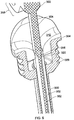
- the apparatus comprises a guidance device and a catheter 350.
- the guidance device comprises an outermost guide tube 300 and an inner guide tube 302.
- the outermost guide tube 300 has a head 304 at its proximal end that includes a screw-threaded portion 306 that allow the outermost guide tube 300 to be secured to a hole formed in the skull of a subject.
- the internal surface along the length of the outermost guide tube has a substantially circular cross-section (although this internal surface could also comprise a slot or cloverleaf profile if a fluid return path between the outermost guide tube and the inner guide tube was required).
- the inner guide tube 302 has a head 310 at its proximal end that can be snap or press fitted into a recess formed in the head 304 of the outermost guide tube 300.
- the outer surface of the inner guide tube 302 has a substantially circular cross-section and is dimensioned to fit within the lumen define by the outermost guide tube.
- the inner surface of the inner guide tube 302 has a "cloverleaf' cross-sectional profile of the type shown in figure 2c .
- a tapered opening 320 with a tapered conical profile i.e. not a cloverleaf profile
- a catheter 350 is also provided that has a fine tube 352 with an outer surface having a substantially circular cross-section.
- the catheter 350 also includes a connector tube 354 having a slighter larger outer diameter than the fine tube 352.
- a tapered region 356 is provided between the fine tube 352 and the connector tube 354.
- An attachment feature 358 e.g. wings with screw holes
- the fine tube 352 of the catheter 350 is dimensioned so as to fit inside and be guided by the inner guide tube 302.
- the cloverleaf type profile of the inner surface of the inner guide tube 302 in combination with the circular cross-section of the fine tube 352 thus provides a series of gaps or conduits that provide a fluid return path as explained above.
- the outermost guide tube 300 is firstly inserted into the brain of a subject through a hole formed in the skull.
- the guide tube 300 is inserted along a known trajectory (e.g. using stereotactic apparatus or a surgical robot) until the screw-threaded portion 306 engages and firmly secures the guide tube 300 tube within the hole formed in the skull.
- the inner guide tube 302 is then inserted into the outermost guide tube 300 until the head 310 of the inner guide tube 302 engages and is retained within the recess formed within the head 304 of the outermost guide tube 300.
- the lumen of the inner guide tube 302 provides a return path for any fluid within the guide tube during this insertion process.
- the catheter 350 is then primed with liquid (e.g. insert liquid) and inserted into the inner guide tube 302.
- the catheter 350 is connected to a fluid pump (not shown) during this insertion procedure so that liquid is pushed though the catheter at a low flow rate to ensure it remains fully primed during insertion.
- the catheter 350 advanced into the inner guide tube 302 until its tapered region 356 engages the tapered opening 320 of the inner guide tube 302. Engagement of the tapered region 356 of the catheter 350 with the tapered opening 320 of the inner guide tube 302 has the effect of sealing the fluid return path. In other words, fluid can be returned along the conduits provided between outer surface of the fine tube 352 and the inner surface of the inner guide tube 302 until the tapered seal is established.
- the fluid return path is thus open during the majority of the catheter insertion process, but is blocked when the catheter is fully inserted.
- This seal thus prevents leakage of fluid from the brain after implantation of the neurosurgical apparatus, whilst still providing a fluid return path during catheter insertion.
- a taper seal is shown in figure 6 , such a fluid seal may of course be provided in a variety of different ways.
Landscapes
- Health & Medical Sciences (AREA)
- Life Sciences & Earth Sciences (AREA)
- Heart & Thoracic Surgery (AREA)
- Animal Behavior & Ethology (AREA)
- General Health & Medical Sciences (AREA)
- Engineering & Computer Science (AREA)
- Biomedical Technology (AREA)
- Veterinary Medicine (AREA)
- Public Health (AREA)
- Surgery (AREA)
- Anesthesiology (AREA)
- Biophysics (AREA)
- Pulmonology (AREA)
- Hematology (AREA)
- Pathology (AREA)
- Molecular Biology (AREA)
- Medical Informatics (AREA)
- Nuclear Medicine, Radiotherapy & Molecular Imaging (AREA)
- Oral & Maxillofacial Surgery (AREA)
- Gastroenterology & Hepatology (AREA)
- Media Introduction/Drainage Providing Device (AREA)
Claims (15)
- Neurochirurgische Vorrichtung, umfassend:eine Führungsvorrichtung (40; 150), die ein Führungsrohr (42; 152; 302) umfasst, undein neurochirurgisches Instrument (60;350) zum Einsetzen in das Führungsrohr (42), wobei die Außenfläche (72) des neurochirurgischen Instruments einen im Wesentlichen kreisförmigen Querschnitt aufweist,wobei, wenn das neurochirurgische Instrument (60; 350) in das Führungsrohr (42; 152; 302) eingesetzt ist, die Innenfläche (46) des Führungsrohres (42; 152; 302) zumindest teilweise mit der Außenfläche des neurochirurgischen Instruments (60; 350) in Eingriff tritt, wodurch das neurochirurgische Instrument (60; 350) entlang eines vordefinierten Pfades durch das Führungsrohr (42; 152; 302) geführt ist,dadurch gekennzeichnet, dass die Führungsvorrichtung ein Führungsrohr (42; 152; 302) umfasst, das eine Innenfläche (46) mit einem Querschnittsprofil aufweist, das eine Mehrzahl von sich um den Umfang beabstandeten Führungsbereichen (48) zum Kontakt mit dem neurochirurgischen Instrument (60; 350) umfasst, wobei die Mehrzahl von Führungsbereichen (48) voneinander um den Umfang durch ein oder mehrere Abstandhalterbereiche (50; 156) getrennt sind, wobei zwischen dem Führungsrohr (42; 152; 302) und dem neurochirurgischen Instrument (60; 350) kein Kontakt besteht, wobei die Abstandhalterbereiche (50; 156) Leitungen bereitstellen, die einen Fluidrückführpfad zum Führen von jeglichem Fluid bereitstellen, das von innerhalb des Führungsrohres (42; 152; 302) während des Einsetzens des neurochirurgischen Instruments (60; 350) in das Führungsrohr (42; 152; 302) verdrängt wird.
- Vorrichtung nach einem der vorhergehenden Ansprüche, wobei die Innenfläche (46) des Führungsrohres (42; 152; 302) ein Querschnittsprofil aufweist, das zumindest drei um den Umfang beabstandete Führungsbereiche (48) zum Kontakt mit dem neurochirurgischen Instrument (60; 350) umfasst.
- Vorrichtung nach einem der vorhergehenden Ansprüche, wobei die Führungsbereiche (48) Vorsprünge von der Innenfläche (46) des Führungsrohres (42; 152; 302) zu der zentralen Längsachse (A) des Führungsrohres (42; 152; 302) umfassen.
- Vorrichtung nach einem der vorhergehenden Ansprüche, wobei die Führungsbereiche (48) nach innen vorragende Rippen oder Grate umfassen, die entlang zumindest eines Teils der Länge der Innenfläche (46) des Führungsrohres (42; 152; 302) verlaufen.
- Vorrichtung nach Anspruch 4, wobei die vorragenden Rippen oder Grate entlang der gesamten Länge der Innenfläche (46) des Führungsrohrs (42; 152; 302) verlaufen.
- Vorrichtung nach einem der vorhergehenden Ansprüche, wobei die Führungsbereiche (48) gleich um den Umfang herum voneinander beabstandet sind.
- Vorrichtung nach einem der vorhergehenden Ansprüche, wobei die Innenfläche (46) des Führungsrohres (42; 152; 302) ein Querschnittsprofil umfasst, das drei um den Umfang beabstandete Führungsbereiche (48) zum Kontakt mit dem neurochirurgischen Instrument (60; 350) umfasst, wobei das Querschnittsprofil die Form eines Kleeblatts aufweist.
- Vorrichtung nach einem der vorhergehenden Ansprüche, wobei, wenn das neurochirurgische Instrument in das Führungsrohr (42; 152; 302) eingesetzt ist, die zentrale Längsachse des neurochirurgischen Instruments im Wesentlichen mit der zentralen Längsachse des Führungsrohres (42; 152; 302) zusammenfällt.
- Vorrichtung nach einem der vorhergehenden Ansprüche, wobei die Führungsvorrichtung das Führungsrohr und ein äußerstes Rohr umfasst, wobei das Führungsrohr in das äußerste Rohr einsetzbar ist.
- Vorrichtung nach einem der vorhergehenden Ansprüche, wobei die Führungsvorrichtung eine Fixierungsvorrichtung (45) zum Fixieren des Führungsrohres (42; 152; 302) an einem Fräsloch aufweist, das in dem Schädel eines Patienten ausgebildet ist.
- Vorrichtung nach einem der vorhergehenden Ansprüche, mit einer Dichtung zum Abdichten des Fluidrückführpfades.
- Vorrichtung nach Anspruch 11, wobei der Fluidrückführpfad eine Fluidrückführung während des Einsetzens des neurochirurgischen Instruments (60; 350) in das Führungsrohr (42; 152; 302) erlaubt und die Dichtung zur Folge hat, dass der Fluidrückführpfad blockiert ist, wenn das neurochirurgische Instrument vollständig in das Führungsrohr (42; 152; 302) eingesetzt ist.
- Vorrichtung nach einem der vorhergehenden Ansprüche, wobei das neurochirurgische Instrument (60; 350) einen neurochirurgischen Katheter umfasst, der ein feines Rohr umfasst, das einen Außendurchmesser von kleiner als 1 mm aufweist.
- Vorrichtung nach Anspruch 13, wobei der neurochirurgische Katheter (60; 350) vor dem Einsetzen in das Führungsrohr (42; 152; 302) mit Flüssigkeit vorgefüllt ist.
- Vorrichtung nach einem der vorhergehenden Ansprüche, wobei zumindest eines von dem neurochirurgischen Katheter (60; 350) und der Führungsvorrichtung (40; 150) Kunststoffmaterial umfasst.
Applications Claiming Priority (2)
| Application Number | Priority Date | Filing Date | Title |
|---|---|---|---|
| GB201404978A GB201404978D0 (en) | 2014-03-20 | 2014-03-20 | Neurosurgical apparatus |
| PCT/GB2015/050798 WO2015140552A1 (en) | 2014-03-20 | 2015-03-19 | Neurosurgical apparatus |
Publications (2)
| Publication Number | Publication Date |
|---|---|
| EP3119310A1 EP3119310A1 (de) | 2017-01-25 |
| EP3119310B1 true EP3119310B1 (de) | 2018-05-02 |
Family
ID=50686585
Family Applications (1)
| Application Number | Title | Priority Date | Filing Date |
|---|---|---|---|
| EP15713221.8A Active EP3119310B1 (de) | 2014-03-20 | 2015-03-19 | Neurochirurgische vorrichtung |
Country Status (4)
| Country | Link |
|---|---|
| US (2) | US11154377B2 (de) |
| EP (1) | EP3119310B1 (de) |
| GB (1) | GB201404978D0 (de) |
| WO (1) | WO2015140552A1 (de) |
Cited By (3)
| Publication number | Priority date | Publication date | Assignee | Title |
|---|---|---|---|---|
| GB202106224D0 (en) | 2021-04-30 | 2021-06-16 | Neurochase Tech Ltd | Neurosurgical device |
| WO2022229662A1 (en) * | 2021-04-30 | 2022-11-03 | Neurochase Technologies Limited | Implantable guide device |
| WO2024089392A1 (en) | 2022-10-25 | 2024-05-02 | Neurochase Technologies Limited | Neurosurgical guide tube |
Families Citing this family (5)
| Publication number | Priority date | Publication date | Assignee | Title |
|---|---|---|---|---|
| CN107233641A (zh) * | 2016-03-29 | 2017-10-10 | 美敦力公司 | 一种用于引导穿刺的皮表留置器械 |
| WO2018044933A1 (en) | 2016-08-30 | 2018-03-08 | The Regents Of The University Of California | Methods for biomedical targeting and delivery and devices and systems for practicing the same |
| JP6868694B2 (ja) * | 2016-12-09 | 2021-05-12 | セント・ジュード・メディカル,カーディオロジー・ディヴィジョン,インコーポレイテッド | 肺静脈隔離バルーンカテーテル |
| CA3070087A1 (en) | 2017-07-17 | 2019-01-24 | Voyager Therapeutics, Inc. | Trajectory array guide system |
| KR102223085B1 (ko) * | 2017-11-01 | 2021-03-04 | 사회복지법인 삼성생명공익재단 | 뇌내 약물 주입 장치 및 뇌내 약물 주입 방법 |
Family Cites Families (19)
| Publication number | Priority date | Publication date | Assignee | Title |
|---|---|---|---|---|
| US4402684A (en) * | 1981-09-16 | 1983-09-06 | The Kendall Company | Cannula with soft tip |
| US4973321A (en) * | 1989-03-17 | 1990-11-27 | Michelson Gary K | Cannula for an arthroscope |
| CA2109955A1 (en) * | 1991-05-24 | 1992-11-26 | Toru Hayakawa | Equipment for intracerebral administration of preparations |
| US5647846A (en) | 1995-05-17 | 1997-07-15 | Scimed Life Systems, Inc. | Catheter having geometrically shaped surface and method of manufacture |
| SE9601974L (sv) * | 1996-05-23 | 1997-10-13 | Elekta Ab | Anordning för att injicera en substans i en kropp, speciellt human eller animalisk |
| DE19701546C1 (de) * | 1997-01-17 | 1998-05-14 | Rolf Dr Med Zumschlinge | Punktionsset |
| US6537205B1 (en) * | 1999-10-14 | 2003-03-25 | Scimed Life Systems, Inc. | Endoscopic instrument system having reduced backlash control wire action |
| GB9928248D0 (en) * | 1999-12-01 | 2000-01-26 | Gill Steven S | An implantable guide tube for neurosurgery |
| GB0205772D0 (en) | 2002-03-12 | 2002-04-24 | Gill Steven S | Catheter |
| AU2003295963B2 (en) * | 2002-11-25 | 2009-09-03 | Boston Scientific Limited | Injection device for treating mammalian body |
| US20100130937A1 (en) * | 2005-06-30 | 2010-05-27 | Abbott Vascular Inc. | Introducer sheath and methods of making |
| US7998128B2 (en) | 2006-05-15 | 2011-08-16 | Therataxis, LLC. | Active delivery and flow redirection: novel devices and method of delivery of materials to patients |
| GB0616411D0 (en) | 2006-08-18 | 2006-09-27 | Renishaw Plc | Neurosurgical instruments |
| JP5052105B2 (ja) | 2006-11-21 | 2012-10-17 | 株式会社スズケン | 経鼻内視鏡用ガイドチューブ |
| EP3093038B1 (de) | 2007-04-18 | 2019-05-22 | Access Scientific, Inc. | Zugangsvorrichtung |
| EP2211973A2 (de) * | 2007-10-08 | 2010-08-04 | Renishaw (Ireland) Limited | Katheter |
| US20090234227A1 (en) | 2008-03-17 | 2009-09-17 | Medtronic Vascular, Inc. | Ribbed Catheter |
| JP6009943B2 (ja) * | 2010-02-08 | 2016-10-19 | アクセス サイエンティフィック、インク. | アクセス装置 |
| GB201203426D0 (en) | 2012-02-28 | 2012-04-11 | Renishaw Plc | Neurosurgical apparatus |
-
2014
- 2014-03-20 GB GB201404978A patent/GB201404978D0/en not_active Ceased
-
2015
- 2015-03-19 WO PCT/GB2015/050798 patent/WO2015140552A1/en not_active Ceased
- 2015-03-19 EP EP15713221.8A patent/EP3119310B1/de active Active
- 2015-03-19 US US15/127,536 patent/US11154377B2/en active Active
-
2021
- 2021-10-25 US US17/509,681 patent/US11559371B2/en active Active
Non-Patent Citations (1)
| Title |
|---|
| None * |
Cited By (7)
| Publication number | Priority date | Publication date | Assignee | Title |
|---|---|---|---|---|
| GB202106224D0 (en) | 2021-04-30 | 2021-06-16 | Neurochase Tech Ltd | Neurosurgical device |
| WO2022229662A1 (en) * | 2021-04-30 | 2022-11-03 | Neurochase Technologies Limited | Implantable guide device |
| WO2022229659A1 (en) | 2021-04-30 | 2022-11-03 | Neurochase Technologies Limited | Neurosurgical device |
| EP4582119A2 (de) | 2021-04-30 | 2025-07-09 | Neurochase Technologies Limited | Neurochirurgische vorrichtung |
| EP4582119A3 (de) * | 2021-04-30 | 2025-09-03 | Neurochase Technologies Limited | Neurochirurgische vorrichtung |
| EP4616882A3 (de) * | 2021-04-30 | 2025-11-05 | Neurochase Technologies Limited | Implantierbare führungsvorrichtung |
| WO2024089392A1 (en) | 2022-10-25 | 2024-05-02 | Neurochase Technologies Limited | Neurosurgical guide tube |
Also Published As
| Publication number | Publication date |
|---|---|
| US20170135778A1 (en) | 2017-05-18 |
| US11559371B2 (en) | 2023-01-24 |
| WO2015140552A1 (en) | 2015-09-24 |
| EP3119310A1 (de) | 2017-01-25 |
| US11154377B2 (en) | 2021-10-26 |
| US20220039901A1 (en) | 2022-02-10 |
| GB201404978D0 (en) | 2014-05-07 |
Similar Documents
| Publication | Publication Date | Title |
|---|---|---|
| US11559371B2 (en) | Neurosurgical apparatus | |
| EP2819739B1 (de) | Neurochirurgische vorrichtung | |
| EP2042212B1 (de) | Katheter für reduzierten Rückfluss bei gezielter Gewebeabgabe eines Therapeutikums | |
| JP6151320B2 (ja) | 経皮薬物送達装置 | |
| EP2919680B1 (de) | Mehrkanalige kanüle | |
| US9833272B2 (en) | Multichannel cannula and methods for using same | |
| EP3157611B1 (de) | Over-the needle-kathetereinsatz | |
| EP2903681B1 (de) | Neurochirurgischen vorrichtung und verfahren | |
| CN104203336B (zh) | 药物存储设备 | |
| EP3068322B1 (de) | Mehrkanalige kanüle | |
| AU2024271158A1 (en) | Neurosurgical device |
Legal Events
| Date | Code | Title | Description |
|---|---|---|---|
| STAA | Information on the status of an ep patent application or granted ep patent |
Free format text: STATUS: THE INTERNATIONAL PUBLICATION HAS BEEN MADE |
|
| PUAI | Public reference made under article 153(3) epc to a published international application that has entered the european phase |
Free format text: ORIGINAL CODE: 0009012 |
|
| STAA | Information on the status of an ep patent application or granted ep patent |
Free format text: STATUS: REQUEST FOR EXAMINATION WAS MADE |
|
| 17P | Request for examination filed |
Effective date: 20161018 |
|
| AK | Designated contracting states |
Kind code of ref document: A1 Designated state(s): AL AT BE BG CH CY CZ DE DK EE ES FI FR GB GR HR HU IE IS IT LI LT LU LV MC MK MT NL NO PL PT RO RS SE SI SK SM TR |
|
| AX | Request for extension of the european patent |
Extension state: BA ME |
|
| DAV | Request for validation of the european patent (deleted) | ||
| DAX | Request for extension of the european patent (deleted) | ||
| GRAP | Despatch of communication of intention to grant a patent |
Free format text: ORIGINAL CODE: EPIDOSNIGR1 |
|
| STAA | Information on the status of an ep patent application or granted ep patent |
Free format text: STATUS: GRANT OF PATENT IS INTENDED |
|
| INTG | Intention to grant announced |
Effective date: 20170824 |
|
| GRAS | Grant fee paid |
Free format text: ORIGINAL CODE: EPIDOSNIGR3 |
|
| GRAA | (expected) grant |
Free format text: ORIGINAL CODE: 0009210 |
|
| STAA | Information on the status of an ep patent application or granted ep patent |
Free format text: STATUS: THE PATENT HAS BEEN GRANTED |
|
| AK | Designated contracting states |
Kind code of ref document: B1 Designated state(s): AL AT BE BG CH CY CZ DE DK EE ES FI FR GB GR HR HU IE IS IT LI LT LU LV MC MK MT NL NO PL PT RO RS SE SI SK SM TR |
|
| REG | Reference to a national code |
Ref country code: GB Ref legal event code: FG4D |
|
| REG | Reference to a national code |
Ref country code: CH Ref legal event code: EP Ref country code: CH Ref legal event code: NV Representative=s name: KIRKER AND CIE S.A., CH Ref country code: AT Ref legal event code: REF Ref document number: 994410 Country of ref document: AT Kind code of ref document: T Effective date: 20180515 |
|
| REG | Reference to a national code |
Ref country code: DE Ref legal event code: R096 Ref document number: 602015010703 Country of ref document: DE Ref country code: IE Ref legal event code: FG4D |
|
| REG | Reference to a national code |
Ref country code: SE Ref legal event code: TRGR |
|
| REG | Reference to a national code |
Ref country code: NL Ref legal event code: MP Effective date: 20180502 |
|
| REG | Reference to a national code |
Ref country code: LT Ref legal event code: MG4D |
|
| PG25 | Lapsed in a contracting state [announced via postgrant information from national office to epo] |
Ref country code: NO Free format text: LAPSE BECAUSE OF FAILURE TO SUBMIT A TRANSLATION OF THE DESCRIPTION OR TO PAY THE FEE WITHIN THE PRESCRIBED TIME-LIMIT Effective date: 20180802 Ref country code: BG Free format text: LAPSE BECAUSE OF FAILURE TO SUBMIT A TRANSLATION OF THE DESCRIPTION OR TO PAY THE FEE WITHIN THE PRESCRIBED TIME-LIMIT Effective date: 20180802 Ref country code: FI Free format text: LAPSE BECAUSE OF FAILURE TO SUBMIT A TRANSLATION OF THE DESCRIPTION OR TO PAY THE FEE WITHIN THE PRESCRIBED TIME-LIMIT Effective date: 20180502 Ref country code: LT Free format text: LAPSE BECAUSE OF FAILURE TO SUBMIT A TRANSLATION OF THE DESCRIPTION OR TO PAY THE FEE WITHIN THE PRESCRIBED TIME-LIMIT Effective date: 20180502 Ref country code: ES Free format text: LAPSE BECAUSE OF FAILURE TO SUBMIT A TRANSLATION OF THE DESCRIPTION OR TO PAY THE FEE WITHIN THE PRESCRIBED TIME-LIMIT Effective date: 20180502 |
|
| PG25 | Lapsed in a contracting state [announced via postgrant information from national office to epo] |
Ref country code: RS Free format text: LAPSE BECAUSE OF FAILURE TO SUBMIT A TRANSLATION OF THE DESCRIPTION OR TO PAY THE FEE WITHIN THE PRESCRIBED TIME-LIMIT Effective date: 20180502 Ref country code: HR Free format text: LAPSE BECAUSE OF FAILURE TO SUBMIT A TRANSLATION OF THE DESCRIPTION OR TO PAY THE FEE WITHIN THE PRESCRIBED TIME-LIMIT Effective date: 20180502 Ref country code: NL Free format text: LAPSE BECAUSE OF FAILURE TO SUBMIT A TRANSLATION OF THE DESCRIPTION OR TO PAY THE FEE WITHIN THE PRESCRIBED TIME-LIMIT Effective date: 20180502 Ref country code: LV Free format text: LAPSE BECAUSE OF FAILURE TO SUBMIT A TRANSLATION OF THE DESCRIPTION OR TO PAY THE FEE WITHIN THE PRESCRIBED TIME-LIMIT Effective date: 20180502 Ref country code: GR Free format text: LAPSE BECAUSE OF FAILURE TO SUBMIT A TRANSLATION OF THE DESCRIPTION OR TO PAY THE FEE WITHIN THE PRESCRIBED TIME-LIMIT Effective date: 20180803 |
|
| REG | Reference to a national code |
Ref country code: AT Ref legal event code: MK05 Ref document number: 994410 Country of ref document: AT Kind code of ref document: T Effective date: 20180502 |
|
| PG25 | Lapsed in a contracting state [announced via postgrant information from national office to epo] |
Ref country code: DK Free format text: LAPSE BECAUSE OF FAILURE TO SUBMIT A TRANSLATION OF THE DESCRIPTION OR TO PAY THE FEE WITHIN THE PRESCRIBED TIME-LIMIT Effective date: 20180502 Ref country code: CZ Free format text: LAPSE BECAUSE OF FAILURE TO SUBMIT A TRANSLATION OF THE DESCRIPTION OR TO PAY THE FEE WITHIN THE PRESCRIBED TIME-LIMIT Effective date: 20180502 Ref country code: AT Free format text: LAPSE BECAUSE OF FAILURE TO SUBMIT A TRANSLATION OF THE DESCRIPTION OR TO PAY THE FEE WITHIN THE PRESCRIBED TIME-LIMIT Effective date: 20180502 Ref country code: RO Free format text: LAPSE BECAUSE OF FAILURE TO SUBMIT A TRANSLATION OF THE DESCRIPTION OR TO PAY THE FEE WITHIN THE PRESCRIBED TIME-LIMIT Effective date: 20180502 Ref country code: EE Free format text: LAPSE BECAUSE OF FAILURE TO SUBMIT A TRANSLATION OF THE DESCRIPTION OR TO PAY THE FEE WITHIN THE PRESCRIBED TIME-LIMIT Effective date: 20180502 Ref country code: PL Free format text: LAPSE BECAUSE OF FAILURE TO SUBMIT A TRANSLATION OF THE DESCRIPTION OR TO PAY THE FEE WITHIN THE PRESCRIBED TIME-LIMIT Effective date: 20180502 Ref country code: SK Free format text: LAPSE BECAUSE OF FAILURE TO SUBMIT A TRANSLATION OF THE DESCRIPTION OR TO PAY THE FEE WITHIN THE PRESCRIBED TIME-LIMIT Effective date: 20180502 |
|
| REG | Reference to a national code |
Ref country code: DE Ref legal event code: R097 Ref document number: 602015010703 Country of ref document: DE |
|
| PG25 | Lapsed in a contracting state [announced via postgrant information from national office to epo] |
Ref country code: IT Free format text: LAPSE BECAUSE OF FAILURE TO SUBMIT A TRANSLATION OF THE DESCRIPTION OR TO PAY THE FEE WITHIN THE PRESCRIBED TIME-LIMIT Effective date: 20180502 Ref country code: SM Free format text: LAPSE BECAUSE OF FAILURE TO SUBMIT A TRANSLATION OF THE DESCRIPTION OR TO PAY THE FEE WITHIN THE PRESCRIBED TIME-LIMIT Effective date: 20180502 |
|
| PLBE | No opposition filed within time limit |
Free format text: ORIGINAL CODE: 0009261 |
|
| STAA | Information on the status of an ep patent application or granted ep patent |
Free format text: STATUS: NO OPPOSITION FILED WITHIN TIME LIMIT |
|
| 26N | No opposition filed |
Effective date: 20190205 |
|
| PG25 | Lapsed in a contracting state [announced via postgrant information from national office to epo] |
Ref country code: SI Free format text: LAPSE BECAUSE OF FAILURE TO SUBMIT A TRANSLATION OF THE DESCRIPTION OR TO PAY THE FEE WITHIN THE PRESCRIBED TIME-LIMIT Effective date: 20180502 |
|
| PG25 | Lapsed in a contracting state [announced via postgrant information from national office to epo] |
Ref country code: MC Free format text: LAPSE BECAUSE OF FAILURE TO SUBMIT A TRANSLATION OF THE DESCRIPTION OR TO PAY THE FEE WITHIN THE PRESCRIBED TIME-LIMIT Effective date: 20180502 |
|
| PG25 | Lapsed in a contracting state [announced via postgrant information from national office to epo] |
Ref country code: LU Free format text: LAPSE BECAUSE OF NON-PAYMENT OF DUE FEES Effective date: 20190319 Ref country code: AL Free format text: LAPSE BECAUSE OF FAILURE TO SUBMIT A TRANSLATION OF THE DESCRIPTION OR TO PAY THE FEE WITHIN THE PRESCRIBED TIME-LIMIT Effective date: 20180502 |
|
| REG | Reference to a national code |
Ref country code: BE Ref legal event code: MM Effective date: 20190331 |
|
| PG25 | Lapsed in a contracting state [announced via postgrant information from national office to epo] |
Ref country code: BE Free format text: LAPSE BECAUSE OF NON-PAYMENT OF DUE FEES Effective date: 20190331 |
|
| PG25 | Lapsed in a contracting state [announced via postgrant information from national office to epo] |
Ref country code: TR Free format text: LAPSE BECAUSE OF FAILURE TO SUBMIT A TRANSLATION OF THE DESCRIPTION OR TO PAY THE FEE WITHIN THE PRESCRIBED TIME-LIMIT Effective date: 20180502 |
|
| PG25 | Lapsed in a contracting state [announced via postgrant information from national office to epo] |
Ref country code: PT Free format text: LAPSE BECAUSE OF FAILURE TO SUBMIT A TRANSLATION OF THE DESCRIPTION OR TO PAY THE FEE WITHIN THE PRESCRIBED TIME-LIMIT Effective date: 20180903 Ref country code: MT Free format text: LAPSE BECAUSE OF NON-PAYMENT OF DUE FEES Effective date: 20190319 |
|
| PG25 | Lapsed in a contracting state [announced via postgrant information from national office to epo] |
Ref country code: CY Free format text: LAPSE BECAUSE OF FAILURE TO SUBMIT A TRANSLATION OF THE DESCRIPTION OR TO PAY THE FEE WITHIN THE PRESCRIBED TIME-LIMIT Effective date: 20180502 |
|
| PG25 | Lapsed in a contracting state [announced via postgrant information from national office to epo] |
Ref country code: IS Free format text: LAPSE BECAUSE OF FAILURE TO SUBMIT A TRANSLATION OF THE DESCRIPTION OR TO PAY THE FEE WITHIN THE PRESCRIBED TIME-LIMIT Effective date: 20180902 |
|
| PG25 | Lapsed in a contracting state [announced via postgrant information from national office to epo] |
Ref country code: HU Free format text: LAPSE BECAUSE OF FAILURE TO SUBMIT A TRANSLATION OF THE DESCRIPTION OR TO PAY THE FEE WITHIN THE PRESCRIBED TIME-LIMIT; INVALID AB INITIO Effective date: 20150319 |
|
| PG25 | Lapsed in a contracting state [announced via postgrant information from national office to epo] |
Ref country code: MK Free format text: LAPSE BECAUSE OF FAILURE TO SUBMIT A TRANSLATION OF THE DESCRIPTION OR TO PAY THE FEE WITHIN THE PRESCRIBED TIME-LIMIT Effective date: 20180502 |
|
| P01 | Opt-out of the competence of the unified patent court (upc) registered |
Effective date: 20230602 |
|
| PGFP | Annual fee paid to national office [announced via postgrant information from national office to epo] |
Ref country code: CH Payment date: 20250401 Year of fee payment: 11 |
|
| REG | Reference to a national code |
Ref country code: CH Ref legal event code: U11 Free format text: ST27 STATUS EVENT CODE: U-0-0-U10-U11 (AS PROVIDED BY THE NATIONAL OFFICE) Effective date: 20260401 |
|
| PGFP | Annual fee paid to national office [announced via postgrant information from national office to epo] |
Ref country code: SE Payment date: 20260319 Year of fee payment: 12 |
|
| PGFP | Annual fee paid to national office [announced via postgrant information from national office to epo] |
Ref country code: GB Payment date: 20260316 Year of fee payment: 12 |
|
| PGFP | Annual fee paid to national office [announced via postgrant information from national office to epo] |
Ref country code: DE Payment date: 20260319 Year of fee payment: 12 Ref country code: IE Payment date: 20260319 Year of fee payment: 12 |
|
| PGFP | Annual fee paid to national office [announced via postgrant information from national office to epo] |
Ref country code: FR Payment date: 20260320 Year of fee payment: 12 |