EP3119637B1 - Unité de couplage et procédé à préparation du couplage d'association entre véhicule éléctrique et station de charge - Google Patents
Unité de couplage et procédé à préparation du couplage d'association entre véhicule éléctrique et station de charge Download PDFInfo
- Publication number
- EP3119637B1 EP3119637B1 EP15713506.2A EP15713506A EP3119637B1 EP 3119637 B1 EP3119637 B1 EP 3119637B1 EP 15713506 A EP15713506 A EP 15713506A EP 3119637 B1 EP3119637 B1 EP 3119637B1
- Authority
- EP
- European Patent Office
- Prior art keywords
- transmitter
- electric vehicle
- charging station
- connection
- directional
- Prior art date
- Legal status (The legal status is an assumption and is not a legal conclusion. Google has not performed a legal analysis and makes no representation as to the accuracy of the status listed.)
- Active
Links
Images
Classifications
-
- B—PERFORMING OPERATIONS; TRANSPORTING
- B60—VEHICLES IN GENERAL
- B60L—PROPULSION OF ELECTRICALLY-PROPELLED VEHICLES; SUPPLYING ELECTRIC POWER FOR AUXILIARY EQUIPMENT OF ELECTRICALLY-PROPELLED VEHICLES; ELECTRODYNAMIC BRAKE SYSTEMS FOR VEHICLES IN GENERAL; MAGNETIC SUSPENSION OR LEVITATION FOR VEHICLES; MONITORING OPERATING VARIABLES OF ELECTRICALLY-PROPELLED VEHICLES; ELECTRIC SAFETY DEVICES FOR ELECTRICALLY-PROPELLED VEHICLES
- B60L53/00—Methods of charging batteries, specially adapted for electric vehicles; Charging stations or on-board charging equipment therefor; Exchange of energy storage elements in electric vehicles
- B60L53/30—Constructional details of charging stations
- B60L53/35—Means for automatic or assisted adjustment of the relative position of charging devices and vehicles
- B60L53/38—Means for automatic or assisted adjustment of the relative position of charging devices and vehicles specially adapted for charging by inductive energy transfer
-
- B—PERFORMING OPERATIONS; TRANSPORTING
- B60—VEHICLES IN GENERAL
- B60L—PROPULSION OF ELECTRICALLY-PROPELLED VEHICLES; SUPPLYING ELECTRIC POWER FOR AUXILIARY EQUIPMENT OF ELECTRICALLY-PROPELLED VEHICLES; ELECTRODYNAMIC BRAKE SYSTEMS FOR VEHICLES IN GENERAL; MAGNETIC SUSPENSION OR LEVITATION FOR VEHICLES; MONITORING OPERATING VARIABLES OF ELECTRICALLY-PROPELLED VEHICLES; ELECTRIC SAFETY DEVICES FOR ELECTRICALLY-PROPELLED VEHICLES
- B60L53/00—Methods of charging batteries, specially adapted for electric vehicles; Charging stations or on-board charging equipment therefor; Exchange of energy storage elements in electric vehicles
- B60L53/10—Methods of charging batteries, specially adapted for electric vehicles; Charging stations or on-board charging equipment therefor; Exchange of energy storage elements in electric vehicles characterised by the energy transfer between the charging station and the vehicle
- B60L53/12—Inductive energy transfer
- B60L53/126—Methods for pairing a vehicle and a charging station, e.g. establishing a one-to-one relation between a wireless power transmitter and a wireless power receiver
-
- B—PERFORMING OPERATIONS; TRANSPORTING
- B60—VEHICLES IN GENERAL
- B60L—PROPULSION OF ELECTRICALLY-PROPELLED VEHICLES; SUPPLYING ELECTRIC POWER FOR AUXILIARY EQUIPMENT OF ELECTRICALLY-PROPELLED VEHICLES; ELECTRODYNAMIC BRAKE SYSTEMS FOR VEHICLES IN GENERAL; MAGNETIC SUSPENSION OR LEVITATION FOR VEHICLES; MONITORING OPERATING VARIABLES OF ELECTRICALLY-PROPELLED VEHICLES; ELECTRIC SAFETY DEVICES FOR ELECTRICALLY-PROPELLED VEHICLES
- B60L53/00—Methods of charging batteries, specially adapted for electric vehicles; Charging stations or on-board charging equipment therefor; Exchange of energy storage elements in electric vehicles
- B60L53/30—Constructional details of charging stations
- B60L53/35—Means for automatic or assisted adjustment of the relative position of charging devices and vehicles
- B60L53/36—Means for automatic or assisted adjustment of the relative position of charging devices and vehicles by positioning the vehicle
-
- B—PERFORMING OPERATIONS; TRANSPORTING
- B60—VEHICLES IN GENERAL
- B60L—PROPULSION OF ELECTRICALLY-PROPELLED VEHICLES; SUPPLYING ELECTRIC POWER FOR AUXILIARY EQUIPMENT OF ELECTRICALLY-PROPELLED VEHICLES; ELECTRODYNAMIC BRAKE SYSTEMS FOR VEHICLES IN GENERAL; MAGNETIC SUSPENSION OR LEVITATION FOR VEHICLES; MONITORING OPERATING VARIABLES OF ELECTRICALLY-PROPELLED VEHICLES; ELECTRIC SAFETY DEVICES FOR ELECTRICALLY-PROPELLED VEHICLES
- B60L53/00—Methods of charging batteries, specially adapted for electric vehicles; Charging stations or on-board charging equipment therefor; Exchange of energy storage elements in electric vehicles
- B60L53/60—Monitoring or controlling charging stations
- B60L53/65—Monitoring or controlling charging stations involving identification of vehicles or their battery types
-
- H—ELECTRICITY
- H02—GENERATION; CONVERSION OR DISTRIBUTION OF ELECTRIC POWER
- H02J—ELECTRIC POWER NETWORKS; CIRCUIT ARRANGEMENTS OR SYSTEMS FOR SUPPLYING OR DISTRIBUTING ELECTRIC POWER; SYSTEMS FOR STORING ELECTRIC ENERGY
- H02J50/00—Circuit arrangements or systems for wireless supply or distribution of electric power
- H02J50/90—Circuit arrangements or systems for wireless supply or distribution of electric power involving detection or optimisation of position, e.g. alignment
-
- H—ELECTRICITY
- H04—ELECTRIC COMMUNICATION TECHNIQUE
- H04B—TRANSMISSION
- H04B7/00—Radio transmission systems, i.e. using radiation field
- H04B7/24—Radio transmission systems, i.e. using radiation field for communication between two or more posts
-
- H—ELECTRICITY
- H02—GENERATION; CONVERSION OR DISTRIBUTION OF ELECTRIC POWER
- H02J—ELECTRIC POWER NETWORKS; CIRCUIT ARRANGEMENTS OR SYSTEMS FOR SUPPLYING OR DISTRIBUTING ELECTRIC POWER; SYSTEMS FOR STORING ELECTRIC ENERGY
- H02J2105/00—Networks for supplying or distributing electric power characterised by their spatial reach or by the load
- H02J2105/30—Networks for supplying or distributing electric power characterised by their spatial reach or by the load the load networks being external to vehicles, i.e. exchanging power with vehicles
- H02J2105/33—Networks for supplying or distributing electric power characterised by their spatial reach or by the load the load networks being external to vehicles, i.e. exchanging power with vehicles exchanging power with road vehicles
- H02J2105/37—Networks for supplying or distributing electric power characterised by their spatial reach or by the load the load networks being external to vehicles, i.e. exchanging power with vehicles exchanging power with road vehicles exchanging power with electric vehicles [EV] or with hybrid electric vehicles [HEV]
-
- H—ELECTRICITY
- H04—ELECTRIC COMMUNICATION TECHNIQUE
- H04B—TRANSMISSION
- H04B5/00—Near-field transmission systems, e.g. inductive or capacitive transmission systems
- H04B5/70—Near-field transmission systems, e.g. inductive or capacitive transmission systems specially adapted for specific purposes
- H04B5/79—Near-field transmission systems, e.g. inductive or capacitive transmission systems specially adapted for specific purposes for data transfer in combination with power transfer
-
- Y—GENERAL TAGGING OF NEW TECHNOLOGICAL DEVELOPMENTS; GENERAL TAGGING OF CROSS-SECTIONAL TECHNOLOGIES SPANNING OVER SEVERAL SECTIONS OF THE IPC; TECHNICAL SUBJECTS COVERED BY FORMER USPC CROSS-REFERENCE ART COLLECTIONS [XRACs] AND DIGESTS
- Y02—TECHNOLOGIES OR APPLICATIONS FOR MITIGATION OR ADAPTATION AGAINST CLIMATE CHANGE
- Y02T—CLIMATE CHANGE MITIGATION TECHNOLOGIES RELATED TO TRANSPORTATION
- Y02T10/00—Road transport of goods or passengers
- Y02T10/60—Other road transportation technologies with climate change mitigation effect
- Y02T10/70—Energy storage systems for electromobility, e.g. batteries
-
- Y—GENERAL TAGGING OF NEW TECHNOLOGICAL DEVELOPMENTS; GENERAL TAGGING OF CROSS-SECTIONAL TECHNOLOGIES SPANNING OVER SEVERAL SECTIONS OF THE IPC; TECHNICAL SUBJECTS COVERED BY FORMER USPC CROSS-REFERENCE ART COLLECTIONS [XRACs] AND DIGESTS
- Y02—TECHNOLOGIES OR APPLICATIONS FOR MITIGATION OR ADAPTATION AGAINST CLIMATE CHANGE
- Y02T—CLIMATE CHANGE MITIGATION TECHNOLOGIES RELATED TO TRANSPORTATION
- Y02T10/00—Road transport of goods or passengers
- Y02T10/60—Other road transportation technologies with climate change mitigation effect
- Y02T10/7072—Electromobility specific charging systems or methods for batteries, ultracapacitors, supercapacitors or double-layer capacitors
-
- Y—GENERAL TAGGING OF NEW TECHNOLOGICAL DEVELOPMENTS; GENERAL TAGGING OF CROSS-SECTIONAL TECHNOLOGIES SPANNING OVER SEVERAL SECTIONS OF THE IPC; TECHNICAL SUBJECTS COVERED BY FORMER USPC CROSS-REFERENCE ART COLLECTIONS [XRACs] AND DIGESTS
- Y02—TECHNOLOGIES OR APPLICATIONS FOR MITIGATION OR ADAPTATION AGAINST CLIMATE CHANGE
- Y02T—CLIMATE CHANGE MITIGATION TECHNOLOGIES RELATED TO TRANSPORTATION
- Y02T90/00—Enabling technologies or technologies with a potential or indirect contribution to GHG emissions mitigation
- Y02T90/10—Technologies relating to charging of electric vehicles
- Y02T90/12—Electric charging stations
-
- Y—GENERAL TAGGING OF NEW TECHNOLOGICAL DEVELOPMENTS; GENERAL TAGGING OF CROSS-SECTIONAL TECHNOLOGIES SPANNING OVER SEVERAL SECTIONS OF THE IPC; TECHNICAL SUBJECTS COVERED BY FORMER USPC CROSS-REFERENCE ART COLLECTIONS [XRACs] AND DIGESTS
- Y02—TECHNOLOGIES OR APPLICATIONS FOR MITIGATION OR ADAPTATION AGAINST CLIMATE CHANGE
- Y02T—CLIMATE CHANGE MITIGATION TECHNOLOGIES RELATED TO TRANSPORTATION
- Y02T90/00—Enabling technologies or technologies with a potential or indirect contribution to GHG emissions mitigation
- Y02T90/10—Technologies relating to charging of electric vehicles
- Y02T90/14—Plug-in electric vehicles
-
- Y—GENERAL TAGGING OF NEW TECHNOLOGICAL DEVELOPMENTS; GENERAL TAGGING OF CROSS-SECTIONAL TECHNOLOGIES SPANNING OVER SEVERAL SECTIONS OF THE IPC; TECHNICAL SUBJECTS COVERED BY FORMER USPC CROSS-REFERENCE ART COLLECTIONS [XRACs] AND DIGESTS
- Y02—TECHNOLOGIES OR APPLICATIONS FOR MITIGATION OR ADAPTATION AGAINST CLIMATE CHANGE
- Y02T—CLIMATE CHANGE MITIGATION TECHNOLOGIES RELATED TO TRANSPORTATION
- Y02T90/00—Enabling technologies or technologies with a potential or indirect contribution to GHG emissions mitigation
- Y02T90/10—Technologies relating to charging of electric vehicles
- Y02T90/16—Information or communication technologies improving the operation of electric vehicles
- Y02T90/167—Systems integrating technologies related to power network operation and communication or information technologies for supporting the interoperability of electric or hybrid vehicles, i.e. smartgrids as interface for battery charging of electric vehicles [EV] or hybrid vehicles [HEV]
-
- Y—GENERAL TAGGING OF NEW TECHNOLOGICAL DEVELOPMENTS; GENERAL TAGGING OF CROSS-SECTIONAL TECHNOLOGIES SPANNING OVER SEVERAL SECTIONS OF THE IPC; TECHNICAL SUBJECTS COVERED BY FORMER USPC CROSS-REFERENCE ART COLLECTIONS [XRACs] AND DIGESTS
- Y04—INFORMATION OR COMMUNICATION TECHNOLOGIES HAVING AN IMPACT ON OTHER TECHNOLOGY AREAS
- Y04S—SYSTEMS INTEGRATING TECHNOLOGIES RELATED TO POWER NETWORK OPERATION, COMMUNICATION OR INFORMATION TECHNOLOGIES FOR IMPROVING THE ELECTRICAL POWER GENERATION, TRANSMISSION, DISTRIBUTION, MANAGEMENT OR USAGE, i.e. SMART GRIDS
- Y04S30/00—Systems supporting specific end-user applications in the sector of transportation
- Y04S30/10—Systems supporting the interoperability of electric or hybrid vehicles
- Y04S30/14—Details associated with the interoperability, e.g. vehicle recognition, authentication, identification or billing
Definitions
- the invention relates to means and methods for establishing an association connection between an electric vehicle and an inductive charging station.
- Inductive charging systems are known for charging an electric vehicle at a charging station. There are coil systems both on the underside of the electric vehicle and in the charging station on the floor. Energy is inductively transferred from the charging station to the electric vehicle via an alternating magnetic field that penetrates this coil system.
- An inductive charging process can be carried out after the electric vehicle has been positioned on the charging station without the driver having to get out of the vehicle or a connection with a charging cable.
- a communication link between the charging station and the electric vehicle has proven successful, which is maintained during the start-up process and during the charging process when the electric vehicle is at a standstill.
- the applicant's disclosed proposal is intended to create an association connection between an electric vehicle and a charging station by coupling a vehicle-side antenna to a charging-station-side antenna, whereby the arrangement of the vehicle-side antenna to the charging-station-side antenna is intended to ensure that only these two antennas have a common connection can build up.
- a directional characteristic of the antenna on the charging station side is designed in such a way that a signal emitted by the antenna on the charging station side can only be received in a predeterminable area around a direct line of sight between the two antennas.
- operation of the antenna on the charging station side is only activated when a predeterminable area is reached, in particular a charging position, in order to make it more difficult to compromise the association connection.
- WO 2014/010447 A1 describes a vehicle-mounted communication device that transmits a request signal while reducing the transmission power in stages. If a response signal from a single power supply device is received, a coupling is automatically carried out with a communication device on the side of the power supply device.
- US 2013/0049456 A1 describes an apparatus and method for controlling a magnetic field using two resonators in a wireless power transmission system.
- DE 10 2012 204 021 A1 describes a method for charging an energy store of an electric motor vehicle, in which energy is transferred from a charging device external to the vehicle to the energy store of the motor vehicle.
- US 2012/0095830 A1 describes an apparatus and method for collecting information about an electric vehicle in real time for auctioning ancillary services.
- the object of the invention is to create measures which ensure a compromise-proof association connection between an electric vehicle and a charging station provided for charging the electric vehicle.
- a method for establishing an association connection between an electric vehicle and a charging station comprises the steps explained below.
- the association connection is established between the electric vehicle and the charging station with the formation of a directional radio link.
- a directional radio link is to be understood as a radio link in which a directional characteristic is provided in a predefined direction on both the transmitter side and the receiver side.
- a directional radio link extends, for example, in a club-like manner from a transmitter placed near the floor of the charging station in the direction of an underside of the electric vehicle.
- the association connection between the electric vehicle and the charging station is checked in cooperation with at least one first transmitter, which effects the directional radio connection, with an omnidirectional transmitter; wherein, in order to check the association connection, a transmission strength of the directional radio link is compared with a transmission strength transmitted via the omnidirectional transmitter; and wherein a negative result of the check is output if the transmission strength transmitted via the omnidirectional transmitter exceeds the transmission strength of the directional radio link.
- Said omnidirectional transmitter is to be understood as a transmitter, that is to say for example an antenna, with an undirected, that is to say for example spherical directional characteristic.
- the previously known directional radio link supports the positioning of the electric vehicle in such a way that a transmission strength measured on the vehicle side, for example, increases progressively with a progressive approach to an intended charging position due to the directional characteristic and finally assumes a maximum value when the intended charging position is reached, the measured on the vehicle side can be used Transmission strength cannot be distinguished solely on the basis of the directional radio connection, whether the radio connection originates from the charging station provided for this purpose or from another compromising transmitter.
- the inventive step of checking the association connection eliminates this deficiency between the electric vehicle and the charging station in cooperation with an omnidirectional transmitter. With a transmission strength preferably measured on the electric vehicle side using the omnidirectional transmitter, a comparison between the transmission strength of the Omnidirectional radio link and the transmission strength of the directional radio link allows.
- connection unit according to the invention having the features of claim 8.
- connection unit for establishing an association connection between an electric vehicle and a charging station, which comprises the functional groups explained below.
- the connection unit has a first interface to at least one first transmitter, which has an essentially directional transmission characteristic.
- the connection unit also has a second interface to at least one second transmitter, which has an essentially omnidirectional, that is to say non-directional transmission characteristic.
- connection unit is set up in cooperation with the first transmitter to set up an association connection between the electric vehicle and the charging station and also set up to check the association connection in cooperation with the second transmitter, the connection unit being set up to check the association connection, a transmission strength of the directional radio connection with to compare a transmission strength transmitted via the omnidirectional transmitter and wherein the connection unit is set up to output a negative result of the check if the transmission strength transmitted via the second transmitter exceeds the transmission strength of the directional radio link.
- the invention further comprises an electric vehicle with a connection unit according to the invention and a charging station with a connection unit according to the invention.
- the directional radio connection takes place between a directional transmitter arranged on the charging station side and a directional transmitter arranged on the electric vehicle side.
- the omnidirectional transmitter is arranged on the electric vehicle side.
- an embodiment is advantageous in which omnidirectional transmitters are arranged both on the electric vehicle side and on the charging station side.
- the mentioned embodiment ensures that transmission, that is to say an opposing transmit and receive operation on both sides, that is to say on the charging station side and on the electric vehicle side, takes place symmetrically.
- This advantageous measure enables identical connection units to be provided both on the part of the electric vehicle and on the part of the charging station.
- the directional transmitter is arranged at a short distance from the omnidirectional transmitter.
- This configuration preferably relates to the electric vehicle, alternatively also to the charging station. Due to the short distance according to this embodiment, a check of the association connection is simplified to the effect that essentially similar operating conditions prevail for both the directional radio connection and for the omnidirectional radio connection, which make it easier to check the association connection.
- the method provides that, in order to check the association connection, a transmission strength of the directional radio connection is compared with a transmission strength transmitted or determined via the omnidirectional transmitter.
- the transmission strength that is to say the signal strength or field strength of the omnidirectional radio link is compared with that of the directional radio link.
- the verification of the transmission strength is the most advantageous verification of the association connection.
- the method provides that a negative result is output to check the association connection if the transmission strength of the transmission strength transmitted or determined with the omnidirectional transmitter exceeds the transmission strength of the directional radio link. It can be assumed that another compromising transmitter is attempting maliciously to override the radio signal sent by the charging station.
- association connection is released as a result of this negative result explained above and / or an error message is output.
- an association connection that has already been started between the electric vehicle and the charging station provided for this purpose is released in order to avoid an incorrect assignment due to a compromising transmitter.
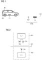
- Fig. 1 shows an electric vehicle EV which, in addition to other - not shown - functional components, has a vehicle-side induction coil C1 and a vehicle-side connection module AU1, which are each arranged, for example, on the underside of the electric vehicle EV.
- the electric vehicle EV approaches an inductive charging station EVSE in order to carry out inductive charging of batteries (not shown) of the electric vehicle EV after the electric vehicle EV has come to a standstill or while driving slowly.
- the inductive charging station EVSE has, in addition to other functional components (not shown), a connection module AU2 on the charging station side and an induction coil C2 on the charging station side.
- the two last-mentioned functional components AU2, C2 are located at the same level as, just above or below a roadway level SFC.
- the electric vehicle EV and the charging station EVSE are associated via an association connection in order to prevent an unauthorized vehicle from being charged.
- Fig. 2 shows a detailed representation of a vehicle-side connection module AU1 and a charging station-side connection module AU2, which is arranged according to the drawing below the road level SFC.
- the illustrated arrangement of both connection modules AU1, AU2 corresponds to an intended parking position in which both connection modules are aligned along their main axis. In such a parking position, the induction coil C1 on the vehicle side is also arranged directly above and essentially congruent with the induction coil C2 on the charging station side.
- connection module AU1 on the electric vehicle side comprises a connection unit CU, a first transmitter TR1 or antenna TR1 and a second transmitter TR2 or antenna TR2.
- the connection module AU2 on the charging station side comprises a connection unit CU and a first transmitter TR1 or antenna TR1.
- the respective first transmitter TR1 has an essentially directional transmission characteristic
- the second transmitter TR2 an essentially omnidirectional transmission characteristic.
- connection module AU2 on the charging station side only has a first directional transmitter TR1.
- a configuration of the charging station-side connection module AU2 that is essentially identical to the electric vehicle-side connection module AU1 is also possible, in which the charging-station-side connection module AU2 also includes a second transmitter TR2 with an essentially omnidirectional transmission characteristic.
- Omnidirectional transmitters send or receive non-directionally, i.e. essentially spherical in the direction of their main axis and are preferably designed as rod antennas.
- Directional or directional transmitters enable the transmission to be aligned in a predeterminable direction. These are preferably designed as antennas with a corresponding geometry. These usually have a lobe-shaped directional characteristic in the direction of their main axis.
- the compromising transmitter could increase its own transmission strength so that it exceeds the transmission strength of the charging station-side connection module AU2.
- a first transmitter TR1 with a directional transmission characteristic would be contained in the connection module AU1 on the electric vehicle side. With such a directional transmitter TR1 alone, however, no assessment can be made as to whether the charging station EVSE or the compromising transmitter is the correct connection partner of the association connection.
- the association connection between the electric vehicle EV and the charging station EVSE is checked by the connection module in the electric vehicle AU1 provided omnidirectional transmitter TR2 provided.
- the transmission strength received by the second transmitter TR2 on the electric vehicle side has a higher or a significantly higher value than the transmission strength received by the first transmitter TR1 on the electric vehicle side, a compromising transmitter is to be assumed.
- the radio connection to be set up for the exchange of positioning, identification and billing information between the charging station EVSE and the electric vehicle EV is preferably maintained via the respective directional first transmitter TR1.
- the approach according to the invention provides for a pair of transmitters TR1, TR2 with an omnidirectional and with a directional transmission characteristic to be provided when an association connection is set up between an electric vehicle EV and a charging station EVSE. After the association connection has been established with the formation of a directional radio connection, this is checked with the participation of an omnidirectional transmitter TR2. This measure enables an undesired association connection with a compromising transmitter to be prevented.
Landscapes
- Engineering & Computer Science (AREA)
- Power Engineering (AREA)
- Transportation (AREA)
- Mechanical Engineering (AREA)
- Computer Networks & Wireless Communication (AREA)
- Signal Processing (AREA)
- Charge And Discharge Circuits For Batteries Or The Like (AREA)
- Electric Propulsion And Braking For Vehicles (AREA)
- Radar, Positioning & Navigation (AREA)
- General Physics & Mathematics (AREA)
- Remote Sensing (AREA)
- Physics & Mathematics (AREA)
- Mobile Radio Communication Systems (AREA)
Claims (8)
- Procédé de fabrication d'un couplage d'association entre un véhicule électrique (EV) et une station de charge (EVSE), comprenant les étapes suivantes :- création du couplage d'association entre le véhicule électrique (EV) et la station de charge (EVSE) par la formation d'une liaison radio dirigée ;- contrôle du couplage d'association entre le véhicule électrique (EV) et la station de charge (EVSE) par l'interaction d'au moins un premier émetteur (TR1), effectuant la liaison radio dirigée, avec un émetteur omnidirectionnel (TR2),dans lequel pour contrôler le couplage d'association, une intensité de transmission de la liaison radio dirigée est comparée à une intensité de transmission transmise par l'émetteur omnidirectionnel (TR2) et dans lequel un résultat négatif du contrôle est fourni, si l'intensité de transmission transmise par l'émetteur omnidirectionnel (TR2) dépasse l'intensité de transmission de la liaison radio dirigée.
- Procédé selon la revendication 1, caractérisé en ce que la liaison radio dirigée se produit entre un émetteur (TR1) dirigé disposé du côté de la station de charge et un émetteur (TR1) dirigé disposé du côté du véhicule électrique.
- Procédé selon l'une des revendications précédentes, caractérisé en ce que l'émetteur omnidirectionnel (TR2) est disposé du côté du véhicule électrique.
- Procédé selon l'une des revendications précédentes 2 et 3, caractérisé en ce que l'émetteur dirigé (TR1) est disposé à faible distance par rapport à l'émetteur omnidirectionnel (TR2).
- Procédé selon l'une des revendications précédentes, caractérisé en ce que le couplage d'association est délié à la suite d'un résultat négatif et / ou un message d'erreur est émis.
- Unité de couplage pour l'établissement d'un couplage d'association entre un véhicule électrique (EV) et une station de charge (EVSE), comprenant :- une interface avec au moins un premier émetteur (TR1), le premier émetteur (TR1) présentant une caractéristique de transmission essentiellement dirigée ; et- une interface avec au moins un deuxième émetteur (TR2), le deuxième émetteur (TR2) présentant une caractéristique de transmission essentiellement omnidirectionnelle ;dans laquelle l'unité de couplage (CU) est agencée en interaction avec le premier émetteur (TR1) pour créer un couplage d'association entre le véhicule électrique (EV) et la station de charge (EVSE) ; etdans laquelle l'unité de couplage (CU) est agencée en interaction avec le deuxième émetteur (TR2) pour contrôler le couplage d'association,dans laquelle l'unité de couplage (CU) pour contrôler le couplage d'association est agencée pour comparer une intensité de transmission de la liaison radio dirigée à une intensité de transmission transmise par l'émetteur omnidirectionnel (TR2) et dans laquelle l'unité de couplage (CU) est agencée pour fournir un résultat négatif du contrôle, si l'intensité de transmission transmise par le deuxième émetteur (TR2) dépasse l'intensité de transmission de la liaison radio dirigée.
- Véhicule électrique, comprenant une unité de liaison selon la revendication 6.
- Station de charge, comprenant une unité de liaison selon la revendication 6.
Applications Claiming Priority (2)
| Application Number | Priority Date | Filing Date | Title |
|---|---|---|---|
| DE102014210813.6A DE102014210813B3 (de) | 2014-06-05 | 2014-06-05 | Mittel und Verfahren zur Herstellung einer Assoziationsverbindung |
| PCT/EP2015/057293 WO2015185244A2 (fr) | 2014-06-05 | 2015-04-02 | Moyens et procédés pour établir une liaison associative |
Publications (2)
| Publication Number | Publication Date |
|---|---|
| EP3119637A2 EP3119637A2 (fr) | 2017-01-25 |
| EP3119637B1 true EP3119637B1 (fr) | 2021-11-17 |
Family
ID=52781107
Family Applications (1)
| Application Number | Title | Priority Date | Filing Date |
|---|---|---|---|
| EP15713506.2A Active EP3119637B1 (fr) | 2014-06-05 | 2015-04-02 | Unité de couplage et procédé à préparation du couplage d'association entre véhicule éléctrique et station de charge |
Country Status (5)
| Country | Link |
|---|---|
| US (1) | US10207593B2 (fr) |
| EP (1) | EP3119637B1 (fr) |
| CN (1) | CN106458052B (fr) |
| DE (1) | DE102014210813B3 (fr) |
| WO (1) | WO2015185244A2 (fr) |
Cited By (2)
| Publication number | Priority date | Publication date | Assignee | Title |
|---|---|---|---|---|
| LU500992B1 (de) | 2021-12-12 | 2023-06-12 | Eclever Entw Ohg | Verfahren zur prüfung von ladesäulen und deren funktionsumfang |
| DE102021214171A1 (de) | 2021-12-12 | 2023-06-15 | eClever Entwicklungs OHG | Verfahren zur prüfung von ladesäulen und deren funktionsumfang |
Families Citing this family (6)
| Publication number | Priority date | Publication date | Assignee | Title |
|---|---|---|---|---|
| DE102014210813B3 (de) | 2014-06-05 | 2015-10-01 | Siemens Aktiengesellschaft | Mittel und Verfahren zur Herstellung einer Assoziationsverbindung |
| DE102015218410B4 (de) * | 2015-09-24 | 2025-11-06 | Schaeffler Technologies AG & Co. KG | Verfahren und Einrichtung zum Bestimmen der Absolutposition eines Fahrzeuges |
| CN108248436A (zh) * | 2018-02-02 | 2018-07-06 | 上海易沐科技有限公司 | 充电桩端控制设备、充电控制系统及车辆充电控制方法 |
| EP3647815A1 (fr) * | 2018-10-31 | 2020-05-06 | Hyundai Motor Company | Appareil d'alignement de position et procédé de transfert de puissance sans fil |
| US11577619B2 (en) * | 2020-12-01 | 2023-02-14 | Rivian Ip Holdings, Llc | Charging station with climate control |
| DE102021211584A1 (de) | 2021-10-14 | 2023-04-20 | Robert Bosch Gesellschaft mit beschränkter Haftung | Verfahren und Vorrichtung zum Authentifizieren eines Kraftfahrzeuges an einer Wasserstofftanksäule |
Family Cites Families (11)
| Publication number | Priority date | Publication date | Assignee | Title |
|---|---|---|---|---|
| EP0882342B1 (fr) * | 1996-02-22 | 2006-07-05 | Kvaser Consultant Ab | Dispositif pour effectuer des messages dans un protocol de reseau zonal à controleur (CAN) |
| WO2008112765A1 (fr) * | 2007-03-15 | 2008-09-18 | Compass Auto Tracker Llc | Appareil et procédé pour dispositif de recherche directionnelle |
| US10343535B2 (en) * | 2010-04-08 | 2019-07-09 | Witricity Corporation | Wireless power antenna alignment adjustment system for vehicles |
| US8594859B2 (en) | 2010-10-18 | 2013-11-26 | Qualcomm Incorporated | Method and system for real-time aggregation of electric vehicle information for real-time auctioning of ancillary services, and real-time lowest cost matching electric vehicle energy demand to charging services |
| US8513915B2 (en) * | 2010-10-21 | 2013-08-20 | GM Global Technology Operations LLC | Vehicle alignment for inductive charging |
| ES2836195T3 (es) * | 2010-10-27 | 2021-06-24 | The Aes Corp | Procedimientos para su uso con equipos eléctricos para gestionar servicios energéticos |
| KR101880030B1 (ko) * | 2011-08-25 | 2018-07-23 | 삼성전자주식회사 | 무선 전력 전송 시스템에서 2개의 소스 공진기를 이용해서 자기장을 제어하는 소스 장치 및 방법 |
| DE102012204021A1 (de) * | 2012-03-14 | 2013-09-19 | Siemens Aktiengesellschaft | Verfahren und System zum Laden eines Energiespeichers eines elektrischen Kraftwagens |
| DE102012012860B4 (de) * | 2012-06-28 | 2025-08-07 | Siemens Aktiengesellschaft | Bereitstellen einer Assoziationsverbindung |
| JP5849876B2 (ja) * | 2012-07-11 | 2016-02-03 | 株式会社豊田自動織機 | 車載通信装置、および通信方法 |
| DE102014210813B3 (de) | 2014-06-05 | 2015-10-01 | Siemens Aktiengesellschaft | Mittel und Verfahren zur Herstellung einer Assoziationsverbindung |
-
2014
- 2014-06-05 DE DE102014210813.6A patent/DE102014210813B3/de not_active Expired - Fee Related
-
2015
- 2015-04-02 US US15/316,363 patent/US10207593B2/en active Active
- 2015-04-02 EP EP15713506.2A patent/EP3119637B1/fr active Active
- 2015-04-02 CN CN201580029799.XA patent/CN106458052B/zh not_active Expired - Fee Related
- 2015-04-02 WO PCT/EP2015/057293 patent/WO2015185244A2/fr not_active Ceased
Non-Patent Citations (1)
| Title |
|---|
| None * |
Cited By (3)
| Publication number | Priority date | Publication date | Assignee | Title |
|---|---|---|---|---|
| LU500992B1 (de) | 2021-12-12 | 2023-06-12 | Eclever Entw Ohg | Verfahren zur prüfung von ladesäulen und deren funktionsumfang |
| DE102021214171A1 (de) | 2021-12-12 | 2023-06-15 | eClever Entwicklungs OHG | Verfahren zur prüfung von ladesäulen und deren funktionsumfang |
| WO2023105093A1 (fr) | 2021-12-12 | 2023-06-15 | eClever Entwicklungs OHG | Procédé de contrôle de bornes de recharge et de leur fonctionnalité |
Also Published As
| Publication number | Publication date |
|---|---|
| US20180147949A1 (en) | 2018-05-31 |
| CN106458052B (zh) | 2020-07-21 |
| WO2015185244A2 (fr) | 2015-12-10 |
| DE102014210813B3 (de) | 2015-10-01 |
| WO2015185244A3 (fr) | 2016-08-25 |
| US10207593B2 (en) | 2019-02-19 |
| EP3119637A2 (fr) | 2017-01-25 |
| CN106458052A (zh) | 2017-02-22 |
Similar Documents
| Publication | Publication Date | Title |
|---|---|---|
| EP3119637B1 (fr) | Unité de couplage et procédé à préparation du couplage d'association entre véhicule éléctrique et station de charge | |
| DE102013016880A1 (de) | Verfahren zur Positionierung eines Fahrzeugs an einer induktiven Ladestation | |
| DE102012214199A1 (de) | Vorrichtung und Verfahren zur Positionierung durch Triangulation | |
| DE102015217389A1 (de) | Verfahren und Vorrichtung zum Betreiben eines Fahrzeugs | |
| DE102016121883B4 (de) | Verfahren und System zum Laden eines Elektrofahrzeugs | |
| EP3551496B1 (fr) | Système de chargement d'un véhicule et procédé pour charger un véhicule | |
| WO2019052800A1 (fr) | Procédé pour établir une liaison de communication entre une station de charge électrique stationnaire et un véhicule automobile, dispositif de commande et système de charge | |
| WO2018041381A1 (fr) | Procédé d'implémentation d'un réseau hertzien de véhicule | |
| WO2019192995A1 (fr) | Dispositif de positionnement d'un véhicule automobile sur un emplacement pour une charge inductive | |
| DE102012221128A1 (de) | Verfahren und Vorrichtung zum Aufladen eines Elektrofahrzeugs, entsprechende Ladesäulenvorrichtung und entsprechendes Elektrofahrzeug | |
| EP3864427B1 (fr) | Dispositif pour déterminer la position d'un objet mobile relativement à un véhicule et véhicule équipé de celui-ci | |
| DE102015217275A1 (de) | Verfahren und Vorrichtung zum Bestimmen, ob ein Kraftfahrzeug momentan manuell oder automatisch geführt wird | |
| EP3079944B1 (fr) | Établissement d'une liaison de charge et d'une liaison de communication associée | |
| DE102014003098A1 (de) | Anordnung und Verfahren zur Versorgung mobiler elektrischer Verbraucher | |
| DE102014221884A1 (de) | Sensoranordnung zur Bereitstellung von Zusatzinformationen in einem induktiven Ladesystem | |
| DE102016015458A1 (de) | Vorrichtung und Verfahren zum induktiven Laden eines elektrischen Energiespeichers eines Fahrzeugs | |
| WO2019086689A1 (fr) | Procédé et système permettant une manœuvre d'évitement par des véhicules autonomes ou partiellement autonomes | |
| EP4058887B1 (fr) | Procédé de transfert de données | |
| DE102011079321A1 (de) | Überwachung von elektrischen Komponenten eines elektrisch betriebenen Kraftfahrzeugs auf Zerstörung | |
| DE102014225906A1 (de) | Bestimmen einer Ladeposition einer Ladeeinrichtung einer Ladestation | |
| WO2017016563A1 (fr) | Système et procédé pour l'alimentation en énergie d'un consommateur électrique et station d'énergie | |
| DE102013219537A1 (de) | Fahrzeugpositionierung beim Laden eines elektrisch antreibbaren Fahrzeugs | |
| DE102017011490A1 (de) | Induktive Ladevorrichtung und Fahrzeug | |
| WO2020002237A1 (fr) | Système de charge de véhicule pour charger un accumulateur d'énergie disposé dans un véhicule | |
| DE102016010931A1 (de) | Verfahren zum Erkennen eines Anhängerbetriebs bei einem Zugfahrzeug mit Anhängerkupplung |
Legal Events
| Date | Code | Title | Description |
|---|---|---|---|
| STAA | Information on the status of an ep patent application or granted ep patent |
Free format text: STATUS: THE INTERNATIONAL PUBLICATION HAS BEEN MADE |
|
| PUAI | Public reference made under article 153(3) epc to a published international application that has entered the european phase |
Free format text: ORIGINAL CODE: 0009012 |
|
| STAA | Information on the status of an ep patent application or granted ep patent |
Free format text: STATUS: REQUEST FOR EXAMINATION WAS MADE |
|
| 17P | Request for examination filed |
Effective date: 20161018 |
|
| AK | Designated contracting states |
Kind code of ref document: A2 Designated state(s): AL AT BE BG CH CY CZ DE DK EE ES FI FR GB GR HR HU IE IS IT LI LT LU LV MC MK MT NL NO PL PT RO RS SE SI SK SM TR |
|
| AX | Request for extension of the european patent |
Extension state: BA ME |
|
| RAP1 | Party data changed (applicant data changed or rights of an application transferred) |
Owner name: SIEMENS AKTIENGESELLSCHAFT |
|
| DAV | Request for validation of the european patent (deleted) | ||
| DAX | Request for extension of the european patent (deleted) | ||
| REG | Reference to a national code |
Ref country code: DE Ref legal event code: R079 Ref document number: 502015015406 Country of ref document: DE Free format text: PREVIOUS MAIN CLASS: B60L0011180000 Ipc: H02J0007020000 |
|
| STAA | Information on the status of an ep patent application or granted ep patent |
Free format text: STATUS: EXAMINATION IS IN PROGRESS |
|
| RIC1 | Information provided on ipc code assigned before grant |
Ipc: G01S 5/00 20060101ALI20200811BHEP Ipc: H02J 13/00 20060101ALI20200811BHEP Ipc: B60L 53/126 20190101ALI20200811BHEP Ipc: H04L 12/24 20060101ALI20200811BHEP Ipc: B60L 53/36 20190101ALI20200811BHEP Ipc: B60L 53/38 20190101ALI20200811BHEP Ipc: H02J 7/02 20160101AFI20200811BHEP Ipc: G01S 5/02 20100101ALI20200811BHEP Ipc: H04B 7/24 20060101ALI20200811BHEP Ipc: H02J 50/90 20160101ALI20200811BHEP Ipc: H04B 5/00 20060101ALI20200811BHEP Ipc: B60L 53/65 20190101ALI20200811BHEP |
|
| 17Q | First examination report despatched |
Effective date: 20200911 |
|
| GRAP | Despatch of communication of intention to grant a patent |
Free format text: ORIGINAL CODE: EPIDOSNIGR1 |
|
| STAA | Information on the status of an ep patent application or granted ep patent |
Free format text: STATUS: GRANT OF PATENT IS INTENDED |
|
| INTG | Intention to grant announced |
Effective date: 20210708 |
|
| GRAS | Grant fee paid |
Free format text: ORIGINAL CODE: EPIDOSNIGR3 |
|
| GRAA | (expected) grant |
Free format text: ORIGINAL CODE: 0009210 |
|
| STAA | Information on the status of an ep patent application or granted ep patent |
Free format text: STATUS: THE PATENT HAS BEEN GRANTED |
|
| AK | Designated contracting states |
Kind code of ref document: B1 Designated state(s): AL AT BE BG CH CY CZ DE DK EE ES FI FR GB GR HR HU IE IS IT LI LT LU LV MC MK MT NL NO PL PT RO RS SE SI SK SM TR |
|
| REG | Reference to a national code |
Ref country code: GB Ref legal event code: FG4D Free format text: NOT ENGLISH |
|
| REG | Reference to a national code |
Ref country code: DE Ref legal event code: R096 Ref document number: 502015015406 Country of ref document: DE |
|
| REG | Reference to a national code |
Ref country code: IE Ref legal event code: FG4D Free format text: LANGUAGE OF EP DOCUMENT: GERMAN |
|
| REG | Reference to a national code |
Ref country code: AT Ref legal event code: REF Ref document number: 1448844 Country of ref document: AT Kind code of ref document: T Effective date: 20211215 |
|
| REG | Reference to a national code |
Ref country code: LT Ref legal event code: MG9D |
|
| REG | Reference to a national code |
Ref country code: NL Ref legal event code: MP Effective date: 20211117 |
|
| PG25 | Lapsed in a contracting state [announced via postgrant information from national office to epo] |
Ref country code: RS Free format text: LAPSE BECAUSE OF FAILURE TO SUBMIT A TRANSLATION OF THE DESCRIPTION OR TO PAY THE FEE WITHIN THE PRESCRIBED TIME-LIMIT Effective date: 20211117 Ref country code: LT Free format text: LAPSE BECAUSE OF FAILURE TO SUBMIT A TRANSLATION OF THE DESCRIPTION OR TO PAY THE FEE WITHIN THE PRESCRIBED TIME-LIMIT Effective date: 20211117 Ref country code: FI Free format text: LAPSE BECAUSE OF FAILURE TO SUBMIT A TRANSLATION OF THE DESCRIPTION OR TO PAY THE FEE WITHIN THE PRESCRIBED TIME-LIMIT Effective date: 20211117 Ref country code: BG Free format text: LAPSE BECAUSE OF FAILURE TO SUBMIT A TRANSLATION OF THE DESCRIPTION OR TO PAY THE FEE WITHIN THE PRESCRIBED TIME-LIMIT Effective date: 20220217 |
|
| PG25 | Lapsed in a contracting state [announced via postgrant information from national office to epo] |
Ref country code: IS Free format text: LAPSE BECAUSE OF FAILURE TO SUBMIT A TRANSLATION OF THE DESCRIPTION OR TO PAY THE FEE WITHIN THE PRESCRIBED TIME-LIMIT Effective date: 20220317 Ref country code: SE Free format text: LAPSE BECAUSE OF FAILURE TO SUBMIT A TRANSLATION OF THE DESCRIPTION OR TO PAY THE FEE WITHIN THE PRESCRIBED TIME-LIMIT Effective date: 20211117 Ref country code: PT Free format text: LAPSE BECAUSE OF FAILURE TO SUBMIT A TRANSLATION OF THE DESCRIPTION OR TO PAY THE FEE WITHIN THE PRESCRIBED TIME-LIMIT Effective date: 20220317 Ref country code: PL Free format text: LAPSE BECAUSE OF FAILURE TO SUBMIT A TRANSLATION OF THE DESCRIPTION OR TO PAY THE FEE WITHIN THE PRESCRIBED TIME-LIMIT Effective date: 20211117 Ref country code: NO Free format text: LAPSE BECAUSE OF FAILURE TO SUBMIT A TRANSLATION OF THE DESCRIPTION OR TO PAY THE FEE WITHIN THE PRESCRIBED TIME-LIMIT Effective date: 20220217 Ref country code: NL Free format text: LAPSE BECAUSE OF FAILURE TO SUBMIT A TRANSLATION OF THE DESCRIPTION OR TO PAY THE FEE WITHIN THE PRESCRIBED TIME-LIMIT Effective date: 20211117 Ref country code: LV Free format text: LAPSE BECAUSE OF FAILURE TO SUBMIT A TRANSLATION OF THE DESCRIPTION OR TO PAY THE FEE WITHIN THE PRESCRIBED TIME-LIMIT Effective date: 20211117 Ref country code: HR Free format text: LAPSE BECAUSE OF FAILURE TO SUBMIT A TRANSLATION OF THE DESCRIPTION OR TO PAY THE FEE WITHIN THE PRESCRIBED TIME-LIMIT Effective date: 20211117 Ref country code: GR Free format text: LAPSE BECAUSE OF FAILURE TO SUBMIT A TRANSLATION OF THE DESCRIPTION OR TO PAY THE FEE WITHIN THE PRESCRIBED TIME-LIMIT Effective date: 20220218 Ref country code: ES Free format text: LAPSE BECAUSE OF FAILURE TO SUBMIT A TRANSLATION OF THE DESCRIPTION OR TO PAY THE FEE WITHIN THE PRESCRIBED TIME-LIMIT Effective date: 20211117 |
|
| PG25 | Lapsed in a contracting state [announced via postgrant information from national office to epo] |
Ref country code: SM Free format text: LAPSE BECAUSE OF FAILURE TO SUBMIT A TRANSLATION OF THE DESCRIPTION OR TO PAY THE FEE WITHIN THE PRESCRIBED TIME-LIMIT Effective date: 20211117 Ref country code: SK Free format text: LAPSE BECAUSE OF FAILURE TO SUBMIT A TRANSLATION OF THE DESCRIPTION OR TO PAY THE FEE WITHIN THE PRESCRIBED TIME-LIMIT Effective date: 20211117 Ref country code: RO Free format text: LAPSE BECAUSE OF FAILURE TO SUBMIT A TRANSLATION OF THE DESCRIPTION OR TO PAY THE FEE WITHIN THE PRESCRIBED TIME-LIMIT Effective date: 20211117 Ref country code: EE Free format text: LAPSE BECAUSE OF FAILURE TO SUBMIT A TRANSLATION OF THE DESCRIPTION OR TO PAY THE FEE WITHIN THE PRESCRIBED TIME-LIMIT Effective date: 20211117 Ref country code: DK Free format text: LAPSE BECAUSE OF FAILURE TO SUBMIT A TRANSLATION OF THE DESCRIPTION OR TO PAY THE FEE WITHIN THE PRESCRIBED TIME-LIMIT Effective date: 20211117 Ref country code: CZ Free format text: LAPSE BECAUSE OF FAILURE TO SUBMIT A TRANSLATION OF THE DESCRIPTION OR TO PAY THE FEE WITHIN THE PRESCRIBED TIME-LIMIT Effective date: 20211117 |
|
| REG | Reference to a national code |
Ref country code: DE Ref legal event code: R097 Ref document number: 502015015406 Country of ref document: DE |
|
| PLBE | No opposition filed within time limit |
Free format text: ORIGINAL CODE: 0009261 |
|
| STAA | Information on the status of an ep patent application or granted ep patent |
Free format text: STATUS: NO OPPOSITION FILED WITHIN TIME LIMIT |
|
| 26N | No opposition filed |
Effective date: 20220818 |
|
| PG25 | Lapsed in a contracting state [announced via postgrant information from national office to epo] |
Ref country code: AL Free format text: LAPSE BECAUSE OF FAILURE TO SUBMIT A TRANSLATION OF THE DESCRIPTION OR TO PAY THE FEE WITHIN THE PRESCRIBED TIME-LIMIT Effective date: 20211117 |
|
| PG25 | Lapsed in a contracting state [announced via postgrant information from national office to epo] |
Ref country code: SI Free format text: LAPSE BECAUSE OF FAILURE TO SUBMIT A TRANSLATION OF THE DESCRIPTION OR TO PAY THE FEE WITHIN THE PRESCRIBED TIME-LIMIT Effective date: 20211117 |
|
| REG | Reference to a national code |
Ref country code: CH Ref legal event code: PL |
|
| REG | Reference to a national code |
Ref country code: BE Ref legal event code: MM Effective date: 20220430 |
|
| PG25 | Lapsed in a contracting state [announced via postgrant information from national office to epo] |
Ref country code: MC Free format text: LAPSE BECAUSE OF FAILURE TO SUBMIT A TRANSLATION OF THE DESCRIPTION OR TO PAY THE FEE WITHIN THE PRESCRIBED TIME-LIMIT Effective date: 20211117 Ref country code: LU Free format text: LAPSE BECAUSE OF NON-PAYMENT OF DUE FEES Effective date: 20220402 Ref country code: LI Free format text: LAPSE BECAUSE OF NON-PAYMENT OF DUE FEES Effective date: 20220430 Ref country code: CH Free format text: LAPSE BECAUSE OF NON-PAYMENT OF DUE FEES Effective date: 20220430 |
|
| PG25 | Lapsed in a contracting state [announced via postgrant information from national office to epo] |
Ref country code: BE Free format text: LAPSE BECAUSE OF NON-PAYMENT OF DUE FEES Effective date: 20220430 |
|
| PG25 | Lapsed in a contracting state [announced via postgrant information from national office to epo] |
Ref country code: IE Free format text: LAPSE BECAUSE OF NON-PAYMENT OF DUE FEES Effective date: 20220402 |
|
| PG25 | Lapsed in a contracting state [announced via postgrant information from national office to epo] |
Ref country code: IT Free format text: LAPSE BECAUSE OF FAILURE TO SUBMIT A TRANSLATION OF THE DESCRIPTION OR TO PAY THE FEE WITHIN THE PRESCRIBED TIME-LIMIT Effective date: 20211117 |
|
| REG | Reference to a national code |
Ref country code: AT Ref legal event code: MM01 Ref document number: 1448844 Country of ref document: AT Kind code of ref document: T Effective date: 20220402 |
|
| PG25 | Lapsed in a contracting state [announced via postgrant information from national office to epo] |
Ref country code: AT Free format text: LAPSE BECAUSE OF NON-PAYMENT OF DUE FEES Effective date: 20220402 |
|
| PG25 | Lapsed in a contracting state [announced via postgrant information from national office to epo] |
Ref country code: HU Free format text: LAPSE BECAUSE OF FAILURE TO SUBMIT A TRANSLATION OF THE DESCRIPTION OR TO PAY THE FEE WITHIN THE PRESCRIBED TIME-LIMIT; INVALID AB INITIO Effective date: 20150402 |
|
| PG25 | Lapsed in a contracting state [announced via postgrant information from national office to epo] |
Ref country code: MK Free format text: LAPSE BECAUSE OF FAILURE TO SUBMIT A TRANSLATION OF THE DESCRIPTION OR TO PAY THE FEE WITHIN THE PRESCRIBED TIME-LIMIT Effective date: 20211117 Ref country code: CY Free format text: LAPSE BECAUSE OF FAILURE TO SUBMIT A TRANSLATION OF THE DESCRIPTION OR TO PAY THE FEE WITHIN THE PRESCRIBED TIME-LIMIT Effective date: 20211117 |
|
| PG25 | Lapsed in a contracting state [announced via postgrant information from national office to epo] |
Ref country code: TR Free format text: LAPSE BECAUSE OF FAILURE TO SUBMIT A TRANSLATION OF THE DESCRIPTION OR TO PAY THE FEE WITHIN THE PRESCRIBED TIME-LIMIT Effective date: 20211117 |
|
| PG25 | Lapsed in a contracting state [announced via postgrant information from national office to epo] |
Ref country code: MT Free format text: LAPSE BECAUSE OF FAILURE TO SUBMIT A TRANSLATION OF THE DESCRIPTION OR TO PAY THE FEE WITHIN THE PRESCRIBED TIME-LIMIT Effective date: 20211117 |
|
| PGFP | Annual fee paid to national office [announced via postgrant information from national office to epo] |
Ref country code: DE Payment date: 20250620 Year of fee payment: 11 |
|
| PGFP | Annual fee paid to national office [announced via postgrant information from national office to epo] |
Ref country code: GB Payment date: 20250507 Year of fee payment: 11 |
|
| PGFP | Annual fee paid to national office [announced via postgrant information from national office to epo] |
Ref country code: FR Payment date: 20250411 Year of fee payment: 11 |