EP3120060B1 - Bistabiles elektrisches ventil, insbesondere für system zur rückgewinnung von benzindämpfen in einem kraftfahrzeug - Google Patents
Bistabiles elektrisches ventil, insbesondere für system zur rückgewinnung von benzindämpfen in einem kraftfahrzeug Download PDFInfo
- Publication number
- EP3120060B1 EP3120060B1 EP15714655.6A EP15714655A EP3120060B1 EP 3120060 B1 EP3120060 B1 EP 3120060B1 EP 15714655 A EP15714655 A EP 15714655A EP 3120060 B1 EP3120060 B1 EP 3120060B1
- Authority
- EP
- European Patent Office
- Prior art keywords
- obturator
- electric valve
- main
- auxiliary
- opening
- Prior art date
- Legal status (The legal status is an assumption and is not a legal conclusion. Google has not performed a legal analysis and makes no representation as to the accuracy of the status listed.)
- Not-in-force
Links
- 230000005291 magnetic effect Effects 0.000 claims description 8
- 239000012530 fluid Substances 0.000 claims description 5
- 239000003302 ferromagnetic material Substances 0.000 claims description 4
- 238000011144 upstream manufacturing Methods 0.000 claims description 3
- 230000004907 flux Effects 0.000 claims 3
- 238000007789 sealing Methods 0.000 description 9
- 238000004804 winding Methods 0.000 description 8
- 239000004952 Polyamide Substances 0.000 description 2
- 229910000831 Steel Inorganic materials 0.000 description 2
- 230000015572 biosynthetic process Effects 0.000 description 2
- 238000006073 displacement reaction Methods 0.000 description 2
- 238000005755 formation reaction Methods 0.000 description 2
- 238000003475 lamination Methods 0.000 description 2
- 239000002991 molded plastic Substances 0.000 description 2
- 229920002647 polyamide Polymers 0.000 description 2
- 230000000717 retained effect Effects 0.000 description 2
- 239000010959 steel Substances 0.000 description 2
- 229910052779 Neodymium Inorganic materials 0.000 description 1
- 230000000694 effects Effects 0.000 description 1
- 239000000463 material Substances 0.000 description 1
- 229910052751 metal Inorganic materials 0.000 description 1
- 239000002184 metal Substances 0.000 description 1
- 238000011084 recovery Methods 0.000 description 1
Images


Classifications
-
- F—MECHANICAL ENGINEERING; LIGHTING; HEATING; WEAPONS; BLASTING
- F16—ENGINEERING ELEMENTS AND UNITS; GENERAL MEASURES FOR PRODUCING AND MAINTAINING EFFECTIVE FUNCTIONING OF MACHINES OR INSTALLATIONS; THERMAL INSULATION IN GENERAL
- F16K—VALVES; TAPS; COCKS; ACTUATING-FLOATS; DEVICES FOR VENTING OR AERATING
- F16K31/00—Actuating devices; Operating means; Releasing devices
- F16K31/02—Actuating devices; Operating means; Releasing devices electric; magnetic
- F16K31/06—Actuating devices; Operating means; Releasing devices electric; magnetic using a magnet, e.g. diaphragm valves, cutting off by means of a liquid
- F16K31/0644—One-way valve
- F16K31/0655—Lift valves
- F16K31/0658—Armature and valve member being one single element
-
- F—MECHANICAL ENGINEERING; LIGHTING; HEATING; WEAPONS; BLASTING
- F16—ENGINEERING ELEMENTS AND UNITS; GENERAL MEASURES FOR PRODUCING AND MAINTAINING EFFECTIVE FUNCTIONING OF MACHINES OR INSTALLATIONS; THERMAL INSULATION IN GENERAL
- F16K—VALVES; TAPS; COCKS; ACTUATING-FLOATS; DEVICES FOR VENTING OR AERATING
- F16K31/00—Actuating devices; Operating means; Releasing devices
- F16K31/02—Actuating devices; Operating means; Releasing devices electric; magnetic
- F16K31/06—Actuating devices; Operating means; Releasing devices electric; magnetic using a magnet, e.g. diaphragm valves, cutting off by means of a liquid
- F16K31/0644—One-way valve
- F16K31/0651—One-way valve the fluid passing through the solenoid coil
-
- F—MECHANICAL ENGINEERING; LIGHTING; HEATING; WEAPONS; BLASTING
- F16—ENGINEERING ELEMENTS AND UNITS; GENERAL MEASURES FOR PRODUCING AND MAINTAINING EFFECTIVE FUNCTIONING OF MACHINES OR INSTALLATIONS; THERMAL INSULATION IN GENERAL
- F16K—VALVES; TAPS; COCKS; ACTUATING-FLOATS; DEVICES FOR VENTING OR AERATING
- F16K31/00—Actuating devices; Operating means; Releasing devices
- F16K31/02—Actuating devices; Operating means; Releasing devices electric; magnetic
- F16K31/06—Actuating devices; Operating means; Releasing devices electric; magnetic using a magnet, e.g. diaphragm valves, cutting off by means of a liquid
- F16K31/08—Actuating devices; Operating means; Releasing devices electric; magnetic using a magnet, e.g. diaphragm valves, cutting off by means of a liquid using a permanent magnet
- F16K31/082—Actuating devices; Operating means; Releasing devices electric; magnetic using a magnet, e.g. diaphragm valves, cutting off by means of a liquid using a permanent magnet using a electromagnet and a permanent magnet
-
- F—MECHANICAL ENGINEERING; LIGHTING; HEATING; WEAPONS; BLASTING
- F16—ENGINEERING ELEMENTS AND UNITS; GENERAL MEASURES FOR PRODUCING AND MAINTAINING EFFECTIVE FUNCTIONING OF MACHINES OR INSTALLATIONS; THERMAL INSULATION IN GENERAL
- F16K—VALVES; TAPS; COCKS; ACTUATING-FLOATS; DEVICES FOR VENTING OR AERATING
- F16K31/00—Actuating devices; Operating means; Releasing devices
- F16K31/02—Actuating devices; Operating means; Releasing devices electric; magnetic
- F16K31/06—Actuating devices; Operating means; Releasing devices electric; magnetic using a magnet, e.g. diaphragm valves, cutting off by means of a liquid
- F16K31/08—Actuating devices; Operating means; Releasing devices electric; magnetic using a magnet, e.g. diaphragm valves, cutting off by means of a liquid using a permanent magnet
- F16K31/084—Actuating devices; Operating means; Releasing devices electric; magnetic using a magnet, e.g. diaphragm valves, cutting off by means of a liquid using a permanent magnet the magnet being used only as a holding element to maintain the valve in a specific position, e.g. check valves
-
- F—MECHANICAL ENGINEERING; LIGHTING; HEATING; WEAPONS; BLASTING
- F16—ENGINEERING ELEMENTS AND UNITS; GENERAL MEASURES FOR PRODUCING AND MAINTAINING EFFECTIVE FUNCTIONING OF MACHINES OR INSTALLATIONS; THERMAL INSULATION IN GENERAL
- F16K—VALVES; TAPS; COCKS; ACTUATING-FLOATS; DEVICES FOR VENTING OR AERATING
- F16K31/00—Actuating devices; Operating means; Releasing devices
- F16K31/02—Actuating devices; Operating means; Releasing devices electric; magnetic
- F16K31/06—Actuating devices; Operating means; Releasing devices electric; magnetic using a magnet, e.g. diaphragm valves, cutting off by means of a liquid
- F16K31/08—Actuating devices; Operating means; Releasing devices electric; magnetic using a magnet, e.g. diaphragm valves, cutting off by means of a liquid using a permanent magnet
- F16K31/086—Actuating devices; Operating means; Releasing devices electric; magnetic using a magnet, e.g. diaphragm valves, cutting off by means of a liquid using a permanent magnet the magnet being movable and actuating a second magnet connected to the closing element
-
- F—MECHANICAL ENGINEERING; LIGHTING; HEATING; WEAPONS; BLASTING
- F02—COMBUSTION ENGINES; HOT-GAS OR COMBUSTION-PRODUCT ENGINE PLANTS
- F02M—SUPPLYING COMBUSTION ENGINES IN GENERAL WITH COMBUSTIBLE MIXTURES OR CONSTITUENTS THEREOF
- F02M25/00—Engine-pertinent apparatus for adding non-fuel substances or small quantities of secondary fuel to combustion-air, main fuel or fuel-air mixture
- F02M25/08—Engine-pertinent apparatus for adding non-fuel substances or small quantities of secondary fuel to combustion-air, main fuel or fuel-air mixture adding fuel vapours drawn from engine fuel reservoir
- F02M2025/0845—Electromagnetic valves
-
- Y—GENERAL TAGGING OF NEW TECHNOLOGICAL DEVELOPMENTS; GENERAL TAGGING OF CROSS-SECTIONAL TECHNOLOGIES SPANNING OVER SEVERAL SECTIONS OF THE IPC; TECHNICAL SUBJECTS COVERED BY FORMER USPC CROSS-REFERENCE ART COLLECTIONS [XRACs] AND DIGESTS
- Y10—TECHNICAL SUBJECTS COVERED BY FORMER USPC
- Y10T—TECHNICAL SUBJECTS COVERED BY FORMER US CLASSIFICATION
- Y10T137/00—Fluid handling
- Y10T137/3367—Larner-Johnson type valves; i.e., telescoping internal valve in expanded flow line section
- Y10T137/3476—Internal servo-motor with internal pilot valve
-
- Y—GENERAL TAGGING OF NEW TECHNOLOGICAL DEVELOPMENTS; GENERAL TAGGING OF CROSS-SECTIONAL TECHNOLOGIES SPANNING OVER SEVERAL SECTIONS OF THE IPC; TECHNICAL SUBJECTS COVERED BY FORMER USPC CROSS-REFERENCE ART COLLECTIONS [XRACs] AND DIGESTS
- Y10—TECHNICAL SUBJECTS COVERED BY FORMER USPC
- Y10T—TECHNICAL SUBJECTS COVERED BY FORMER US CLASSIFICATION
- Y10T137/00—Fluid handling
- Y10T137/3367—Larner-Johnson type valves; i.e., telescoping internal valve in expanded flow line section
- Y10T137/3476—Internal servo-motor with internal pilot valve
- Y10T137/353—Pilot controlled passage in nose or needle
Definitions
- the present invention relates to a bistable electric valve, in particular for a system for recovering petrol vapours in a motor vehicle of the kind defined in the preamble of claim 1.
- a bistable electric valve of that kind s disclosed in DE 103 07 059 A1 A bistable electric valve of that kind s disclosed in DE 103 07 059 A1 .
- bistable electric valve is known for example from US 2004/0040547 A1 .
- bistable electric valve for use in refrigerating circuits, is known from FR 2 600 150 A1 .
- An object of the present invention is to provide a bistable electric valve of the improved type, in particular for use in a system for recovering petrol vapours in a motor vehicle.
- FIG. 1 denotes overall a bistable electric valve according to the present invention intended in particular for use in a system for recovery of petrol vapours in a motor vehicle.
- the electric valve 1 comprises a hollow support housing, denoted overall by 2, comprising an essentially tubular central portion 3 at the ends of which respective terminal portions indicated by 4 and 5 are connected.
- the portions 3 to 5 of the support housing 2 may be conveniently made of moulded plastic material, for example a polyamide 6-6.
- the intermediate portion 3 of the support housing 2 has essentially cylindrical opposite terminal parts 3a, 3b which have substantially the same diameter, and an intermediate portion 3c which is also essentially cylindrical and has a smaller diameter.
- the end portions 3a and 3b are connected to the intermediate portion 3c by means of two annular walls 3d and 3e integral therewith (see in particular Figures 2 and 3 ).
- terminal portions 4 and 5 of the support housing 2 have respective annular walls 4a and 5a from the central opening of which respective tubular connecting formations 4b and 5b acting as an outlet and an inlet, respectively, extend in opposite directions, said formations being axially aligned with each other along the axis A-A of the electric valve 1.
- a control winding or solenoid 6 is housed outside the support housing 2, inside the annular cavity defined between the walls 3c, 3d and 3e and can be connected to a control circuit (not shown) by means of electric terminals 7 connected to its ends.
- a closed magnetic circuit extends around the support housing 2, said circuit being formed with two laminations 8, for example made of metal, folded in an L-shape and having their respective ends seamed together (see also Figure 3 ).
- a chamber 10 is defined inside the housing 2 and is able to communicate with the unions 4b and 5b, as will be described more clearly below.
- the unions 4a and 5b in the embodiment shown extend through corresponding openings 9 provided in facing sections of the laminations 8 which form the external magnetic circuit (see for example Figures 1 and 2 ).
- 11 and 12 denote two annular pole shoes made of ferromagnetic material, for example steel, having respective central openings 11a and 12a which are aligned with the unions 4b and 5b, respectively, of the support housing 2.
- Two annular permanent magnets 13 and 14, for example made of FeSt, coaxial with the longitudinal axis A-A of the electric valve 1, are positioned inside the support housing 2 between the pole shoes 11, 12 and the annular walls 3d, 3e.
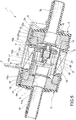
- the chamber 10 defined inside the support housing 2 contains an axially displaceable main obturator made of ferromagnetic material, for example steel, denoted overall by 15 in Figures 2 to 5 .
- the obturator 15 in the embodiment shown comprises a first axial portion 15a which is essentially cup-shaped, with its inlet opening directed towards the pole shoe 11.
- the edge of the inlet opening along the portion 15a of the obturator 15 faces a sealing O-ring 16 fixed to the surface of the pole shoe 11 which faces the obturator 15.
- the arrangement is such that when the portion 15a of the obturator 15 with its annular edge of the inlet opening presses against the sealing ring 16, the chamber 10 is disconnected from the opening 11a of the pole shoe 11 and the union 4b.
- the arrangement is moreover such that, when the obturator 15 is in the working position shown in Figures 2 and 3 and its portion 15a presses against the sealing ring 16, it is able to be retained in this position owing to the attraction exerted on it by the permanent magnet 13, via the pole shoe 11.
- the portion 15a of the obturator 15 has a transverse end wall 15c inside which a calibrated central through-hole 17 is formed, said hole allowing communication between the upstream and downstream regions of this wall.
- the main obturator 15 also has a second portion, indicated by 15b, in Figures 2 et seq. This portion is also essentially cylindrical tubular and extends on the opposite side to the portion 15a relative to the transverse wall 15c.
- a plurality of longitudinal through-slits 15d are formed in the side wall of the portion 15b of the obturator, said through-slits being able to place in communication with each other the radially inner region and the radially outer region of said portion of the obturator 15.
- This ring 18 axially faces a sealing O-ring 19 fixed to the pole shoe 12.
- annular member 18 Inside the annular member 18 there extends an essentially cup-shaped body 20 arranged so that its inlet opening is directed towards the intermediate transverse wall 15c of the main obturator 15.
- This body 20 is connected to the support element 18 by means of a plurality of spokes 18a between which a plurality of axial passages 18b are defined.
- the ring 18, the body 20 and the spokes 18a may be conveniently formed as one piece.
- the passages 18b face the opening 12a of the pole shoe 12.
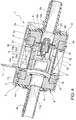
- the main obturator 15 is able to assume a second working position, shown in Figure 4 , where the support ring 18, integral therewith, presses against the sealing O-ring 19.
- the chamber 10 moreover communicates with the region inside the union 4b and the opening 11a of the pole shoe 11, since the portion 15a of the obturator 15 is spaced from the sealing O-ring 16. Therefore, in the condition shown in Figure 4 , the electric valve 1 is completely pervious between the unions 4b and 5b.
- a permanent magnet 21 is mounted axially displaceable inside the body 20.
- This permanent magnet on the side directed towards the intermediate transverse wall 15c of the main obturator 15 has an auxiliary obturator 22 operationally cooperating with the calibrated hole 17 in order to form a so-called pilot valve.
- a spring 23 may be arranged between the permanent magnet 21 and the end wall 20a of the body 20, said spring tending to push this permanent magnet and the associated obturator 22 towards the intermediate transverse wall 15c of the obturator 15 and the calibrated through-hole 17 of the latter.
- the main obturator 15 as already mentioned above, is able to assume a first and a second stable working position.
- the main obturator 15 enables communication between the chamber 10, the opening 11a and the union 4b, in fact establishing communication between the unions 4b and 5b.
- the main obturator 15 is able to be kept in the position shown in Figure 4 by the effect of the attraction exerted on it by the permanent magnet 14.
- the inlet union 5b of the electric valve 1 is intended to be connected to a fluid source under a certain pressure, for example a canister containing petrol vapours. This fluid, when the electric valve is closed, fills the chamber 16.
- the control winding or solenoid 6 is energized, by means of a current flow circulating in a first predetermined direction, the magnetic field generated by this winding or solenoid causes firstly a displacement of the permanent magnet 21 and the associated auxiliary obturator 22 away from the intermediate transverse wall 15c of the main obturator 15, as shown in Figure 3 .
- a first condition is thus assumed where the chamber 10 is placed in communication with the opening 11a and the union 4b via the small calibrated hole 17.
- the pressurized fluid contained in the chamber 10 may therefore gradually spread through the hole 17, beyond the wall 15c of the main obturator. As a result the pressure which this fluid inside the chamber 10 exerts against the main obturator 15 gradually diminishes in the direction of the sealing O-ring 16.
- the chamber 10 is placed in communication with the opening 11a and the union 4b via a very broad section such that the unions 5b and 4b fully communicate.
- the winding or solenoid 6 may therefore be de-energized, but the main obturator 15 remains in the second working position, shown in Figure 4 , owing to the attraction exerted on it now by the permanent magnet 14.
- This condition is again a stable condition in which the electric valve 1 does not use energy since the winding or solenoid 6 is de-energized.
- the auxiliary obturator 22 closes off the calibrated passage 17. This, however, does not prevent full communication between the unions 5b and 4b through the passages 18b defined in the annular support member 18, the eyelets 15d of the main obturator 15 and the opening 11a formed in the pole shoe 11.
- the electric valve 1 is then closed again.
- This counter-pressure may then be vented inside the chamber 10, through the momentarily open hole 17.
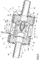
- Figure 6 shows a variation of embodiment.
- the variant according to Figure 6 differs from the embodiment described previously essentially because the two groups formed by the pole shoes 11 and 12 and by the associated permanent magnets 13 and 14 are wholly replaced by corresponding annular permanent magnets indicated by 31 and 32 in Figure 6 .
- These magnets 31 and 32 may be made of plastoferrite or plasto-neodymium.
Landscapes
- Engineering & Computer Science (AREA)
- General Engineering & Computer Science (AREA)
- Mechanical Engineering (AREA)
- Physics & Mathematics (AREA)
- Electromagnetism (AREA)
- Magnetically Actuated Valves (AREA)
Claims (7)
- Bistabiles elektrisches Ventil (1), insbesondere für ein System zum Rückgewinnen von Benzindämpfen in einem Kraftfahrzeug, das folgende Merkmale aufweist:ein hohles Gehäuse (2), in dem eine Kammer (10) definiert ist, mit einer ersten und einer zweiten Öffnung (11a, 12a);ein Hauptabschlusselement (15), das aus einem ferromagnetischen Material hergestellt ist, innerhalb der Kammer (10) angeordnet ist und zwischen einer ersten und einer zweiten Arbeitsposition (Figur 2; Figur 4) verschiebbar ist, in der dasselbe die erste Öffnung (11a) zum Aktivieren bzw. Sperren eines Flusses von Fluid von der zweiten Öffnung (12a) zu der ersten Öffnung (11a) schließt bzw. öffnet;einen ersten und einen zweiten Permanentmagneten (13, 14; 31, 32), die in dem Gehäuse (2) in der Umgebung der ersten bzw. zweiten Öffnung (11a, 12a) befestigt und entworfen sind, um das Hauptabschlusselement (15) in der ersten bzw. zweiten Arbeitsposition zu halten;wobei das elektrische Ventil (1) dadurch gekennzeichnet ist, dass es Folgendes aufweist:ein Hauptabschlusselement (15) mit zumindest einem kalibrierten Durchgangsloch (17) zum Einrichten einer Kommunikation zwischen der Region in Flussrichtung vor und der Region in Flussrichtung nach dem Abschlusselement (15);ein Hilfsabschlusselement (22), das in der Region, die zwischen dem Hauptabschlusselement (15) und der zweiten Öffnung (12a) besteht, in Flussrichtung vor dem Durchgangsloch (17) des Hauptabschlusselements (15) zwischen einer ersten und einer zweiten Position bewegbar angebracht ist, in der dasselbe das Durchgangsloch (17) schließt bzw. öffnet;einen dritten Permanentmagneten (21), der in das Hilfsabschlusselement (22) integriert ist; undein Steuersolenoid (6), das um den Weg des Hauptabschlusselements (15) und des Hilfsabschlusselements (22) herum angeordnet und entworfen ist, um einen Magnetfluss zu erzeugen, der dazu neigt, das Anziehen des Hauptabschlusselements (15) und des Hilfsabschlusselements (22) in Richtung einer oder der anderen der ersten und der zweiten Öffnung (11a, 12a) zu bewirken;wobei die Anordnung derart ist, dass, wenn eine Energieversorgung des Steuersolenoids (6) abgeschaltet ist, das elektrische Ventil (1):einen ersten stabilen Zustand, in dem das Hilfsabschlusselement (22) das Durchgangsloch (17) des Hauptabschlusselements (15) verschließt und Letzteres in der ersten Arbeitsposition angeordnet ist, in der dasselbe die erste Öffnung (11a) schließt, odereinen zweiten stabilen Zustand annimmt, in dem das Hauptabschlusselement (15) sich in dem zweiten Arbeitszustand befindet, in dem dasselbe die erste Öffnung (11a) öffnet; undwenn das Steuersolenoid (6) mit Energie versorgt wird, während sich das elektrische Ventil (1) in dem ersten stabilen Zustand (Figur 2) befindet, der Magnetfluss, der durch das Solenoid (6) erzeugt wird, bewirkt, dass der dritte Permanentmagnet (21) und das Hilfsabschlusselement (22) in den zweiten Zustand kommen, in dem das Hilfsabschlusselement (22) das Durchgangsloch (17) des Hauptabschlusselements (15) öffnet, und dass danach das Hauptabschlusselement (15) in die zuvor erwähnte zweite Position kommt und das Hilfsabschlusselement (22) in seine erste Position zurückkehrt; undwenn das Solenoid (6) mit Energie versorgt wird, während sich das elektrische Ventil (1) in dem zweiten stabilen Zustand befindet, der Magnetfluss, der durch das Solenoid (6) erzeugt wird, bewirkt, dass das Hauptabschlusselement (15) und das Hilfsabschlusselement (22) in die jeweiligen ersten Positionen zurückkehren.
- Bistabiles elektrisches Ventil gemäß Anspruch 1, bei dem das Gehäuse (2) einen ersten und einen zweiten Polschuh (11, 12; Figuren 2-5) aufweist, die aus einem ferromagnetischen Material hergestellt sind, in denen die erste bzw. zweite Öffnung (11a, 12a) vorgesehen sind, wobei der erste und der zweite Permanentmagnet (13, 14) benachbart zu den Polschuhen (11, 12) sind.
- Bistabiles elektrisches Ventil gemäß Anspruch 1, bei dem die erste und die zweite Öffnung (11a, 12a) in dem ersten bzw. zweiten Permanentmagneten (31, 32; Figur 6) vorgesehen sind.
- Bistabiles elektrisches Ventil gemäß einem der vorherigen Ansprüche, bei dem der dritte Permanentmagnet (21) in einem Körper (20) bewegbar ist, der in das Hauptabschlusselement (15) integriert ist.
- Bistabiles elektrisches Ventil gemäß einem der vorherigen Ansprüche, bei dem die erste und die zweite Öffnung (11a, 12a), die Permanentmagneten (13, 14, 21) und die Abschlusselemente (15, 22) koaxial zueinander sind.
- Bistabiles elektrisches Ventil gemäß einem der vorherigen Ansprüche, bei dem eine Federeinrichtung (23) dazu neigt, den dritten Permanentmagneten (21) in Richtung des kalibrierten Durchgangslochs (17) des Hauptabschlusselements (15) zu treiben.
- System zum Rückgewinnen von Benzindämpfen in einem Kraftfahrzeug, das ein bistabiles elektrisches Ventil (1) gemäß einem oder mehreren der vorherigen Ansprüche aufweist.
Applications Claiming Priority (2)
| Application Number | Priority Date | Filing Date | Title |
|---|---|---|---|
| ITTO20140224 | 2014-03-19 | ||
| PCT/IB2015/051976 WO2015140726A1 (en) | 2014-03-19 | 2015-03-18 | Bistable electric valve, in particular for a system for recovering petrol vapours in a motor vehicle |
Publications (2)
| Publication Number | Publication Date |
|---|---|
| EP3120060A1 EP3120060A1 (de) | 2017-01-25 |
| EP3120060B1 true EP3120060B1 (de) | 2018-02-28 |
Family
ID=50982995
Family Applications (1)
| Application Number | Title | Priority Date | Filing Date |
|---|---|---|---|
| EP15714655.6A Not-in-force EP3120060B1 (de) | 2014-03-19 | 2015-03-18 | Bistabiles elektrisches ventil, insbesondere für system zur rückgewinnung von benzindämpfen in einem kraftfahrzeug |
Country Status (4)
| Country | Link |
|---|---|
| US (1) | US9970566B2 (de) |
| EP (1) | EP3120060B1 (de) |
| CN (1) | CN106104125A (de) |
| WO (1) | WO2015140726A1 (de) |
Families Citing this family (14)
| Publication number | Priority date | Publication date | Assignee | Title |
|---|---|---|---|---|
| EP3259466B1 (de) | 2015-02-19 | 2018-12-12 | Bitron S.p.A. | Bistabiler elektronisches ventil, insbesondere für ein system zur rückführung von benzindämpfe in einem kraftfahrzeug |
| CN109416135B (zh) * | 2016-06-27 | 2020-12-25 | 康斯博格汽车股份有限公司 | 具有带第一永磁体和第二永磁体的阀的流体路由设备 |
| CN107830182A (zh) * | 2017-11-16 | 2018-03-23 | 厦门建霖健康家居股份有限公司 | 一种带有磁铁的电磁阀 |
| FR3076881B1 (fr) * | 2018-01-17 | 2020-05-22 | Delabie | Electrovanne bistable de configuration tubulaire avec entree et sortie en ligne |
| DE102018001048A1 (de) * | 2018-02-09 | 2019-08-14 | Atlas Copco Ias Gmbh | Dosierventil |
| FR3079014B1 (fr) * | 2018-03-16 | 2020-04-17 | Serac Group | Actionneur de vanne, vanne et machine correspondantes |
| DE102018109640A1 (de) | 2018-04-23 | 2019-10-24 | Tries Gmbh & Co. Kg | Monostabiles elektromagnetisches Hydraulikventil sowie Herstellungsverfahren hierfür |
| AT16929U1 (de) * | 2019-05-28 | 2020-12-15 | Zieger Dipl Ing Andreas | Kombinationsventil |
| JP7377036B2 (ja) * | 2019-09-09 | 2023-11-09 | カヤバ株式会社 | ソレノイド、電磁弁、及び緩衝器 |
| JP7172933B2 (ja) * | 2019-09-23 | 2022-11-16 | 浜名湖電装株式会社 | パージ制御弁装置 |
| CN111022401B (zh) * | 2019-11-18 | 2021-08-31 | 杭州电子科技大学 | 一种用于软体机器人的双稳态软通断阀及其使用方法 |
| US11721465B2 (en) | 2020-04-24 | 2023-08-08 | Rain Bird Corporation | Solenoid apparatus and methods of assembly |
| CN113669462B (zh) * | 2021-08-19 | 2022-07-08 | 浙江大学 | 一种低功耗的双稳态电磁阀 |
| US12404948B2 (en) * | 2022-11-24 | 2025-09-02 | Hydrotek Corporation | Solenoid valve |
Family Cites Families (14)
| Publication number | Priority date | Publication date | Assignee | Title |
|---|---|---|---|---|
| JPS54149928A (en) * | 1978-05-16 | 1979-11-24 | Aisin Seiki | Motor operation type flow quantity proportional control valve |
| US4403765A (en) * | 1979-11-23 | 1983-09-13 | John F. Taplin | Magnetic flux-shifting fluid valve |
| IT1203572B (it) | 1986-06-11 | 1989-02-15 | Elbi Int Spa | Circuito frigorigeno per impianti frigoriferi includenti una fluralilita'di ambienti refrigeranti ed elettrovalvola deviatrice bistabile utilizzabile in tale circuito |
| DE3730381C2 (de) * | 1987-09-10 | 1997-06-12 | Kuhnke Gmbh Kg H | Bistabiles Magnetventil mit dauermagnetischer Haltekraft |
| US5351934A (en) * | 1992-12-15 | 1994-10-04 | Alliedsignal, Inc. | Proportional solenoid valve |
| US5529281A (en) * | 1994-08-24 | 1996-06-25 | The United States Of America As Represented By The Administrator Of National Aeronautics And Space | Dual-latching solenoid-actuated valve assembly |
| US5529387A (en) * | 1994-09-06 | 1996-06-25 | Valcor Engineering Corporation | Solenoid operated discharging orifice shutoff valve |
| IT1308473B1 (it) | 1999-05-05 | 2001-12-17 | Bitron Spa | Elettrovalvola bistabile perfezionata |
| DE10216687A1 (de) * | 2002-02-19 | 2003-08-28 | Aweco Appliance Sys Gmbh & Co | Bistabiles elektromagnetisches Ventil |
| US20040040547A1 (en) | 2002-08-30 | 2004-03-04 | Kirk Ivens | Self latching canister vent solenoid valve |
| CN2620139Y (zh) * | 2003-05-10 | 2004-06-09 | 宜兴市四通家电配套厂 | 改进的冰箱用双稳态脉冲电磁阀 |
| US6994308B1 (en) * | 2004-08-25 | 2006-02-07 | Wei-Ching Wang | In-tube solenoid gas valve |
| CN201232774Y (zh) * | 2008-05-28 | 2009-05-06 | 浙江三花制冷集团有限公司 | 一种双稳态电磁阀 |
| EP2881636B1 (de) * | 2013-12-04 | 2016-09-07 | Sidel S.p.a. Con Socio Unico | Ventil mit magnetischem Stellglied |
-
2015
- 2015-03-18 CN CN201580012367.8A patent/CN106104125A/zh active Pending
- 2015-03-18 EP EP15714655.6A patent/EP3120060B1/de not_active Not-in-force
- 2015-03-18 WO PCT/IB2015/051976 patent/WO2015140726A1/en not_active Ceased
- 2015-03-18 US US15/123,099 patent/US9970566B2/en not_active Expired - Fee Related
Also Published As
| Publication number | Publication date |
|---|---|
| US20170067572A1 (en) | 2017-03-09 |
| US9970566B2 (en) | 2018-05-15 |
| EP3120060A1 (de) | 2017-01-25 |
| WO2015140726A1 (en) | 2015-09-24 |
| CN106104125A (zh) | 2016-11-09 |
Similar Documents
| Publication | Publication Date | Title |
|---|---|---|
| EP3120060B1 (de) | Bistabiles elektrisches ventil, insbesondere für system zur rückgewinnung von benzindämpfen in einem kraftfahrzeug | |
| EP2501970B1 (de) | Elektromagnetische ventilanordnung | |
| EP3259466B1 (de) | Bistabiler elektronisches ventil, insbesondere für ein system zur rückführung von benzindämpfe in einem kraftfahrzeug | |
| EP1582791B1 (de) | Elektromagnetisches Ventil | |
| US20040159812A1 (en) | Solenoid-operated valve | |
| EP1455127B1 (de) | Elektromagnetisches Ventil | |
| JPH0626588A (ja) | ソレノイド弁 | |
| US4322057A (en) | Electromagnetically operated valve unit | |
| JP6909805B2 (ja) | ソレノイドバルブ | |
| KR101900587B1 (ko) | 폴 피스와 플럭스 슬리브의 정렬불량에 강한 솔레노이드 | |
| JP2015223072A (ja) | 磁極片配列部材を備えた電気機械式ソレノイド | |
| US20170030475A1 (en) | Electrically operated valve | |
| US20190186651A1 (en) | Anti-latching and damping shim for an electromagnetic actuator | |
| KR20170044200A (ko) | 전자기 작동식 팽창 밸브 | |
| JP6560143B2 (ja) | 圧力流体制御装置 | |
| WO2016013537A1 (ja) | 電磁弁 | |
| JP4998315B2 (ja) | 電磁弁 | |
| KR102179015B1 (ko) | 개선된 개방 및 폐쇄 거동을 가진 솔레노이드 밸브 | |
| EP3179488B1 (de) | Magnetkreisschaltvorrichtung mit einseitiger anziehung | |
| KR101703824B1 (ko) | 전자 비례 감압 밸브 | |
| JP2017015150A (ja) | 圧力流体制御装置 | |
| KR101833859B1 (ko) | 유압식 밸브용 차단부 및 유압식 밸브 | |
| JP6028626B2 (ja) | 電磁弁 | |
| JPH04136579A (ja) | 電磁式切換弁 | |
| JP6591802B2 (ja) | 圧力流体制御装置 |
Legal Events
| Date | Code | Title | Description |
|---|---|---|---|
| PUAI | Public reference made under article 153(3) epc to a published international application that has entered the european phase |
Free format text: ORIGINAL CODE: 0009012 |
|
| 17P | Request for examination filed |
Effective date: 20160930 |
|
| AK | Designated contracting states |
Kind code of ref document: A1 Designated state(s): AL AT BE BG CH CY CZ DE DK EE ES FI FR GB GR HR HU IE IS IT LI LT LU LV MC MK MT NL NO PL PT RO RS SE SI SK SM TR |
|
| AX | Request for extension of the european patent |
Extension state: BA ME |
|
| DAV | Request for validation of the european patent (deleted) | ||
| DAX | Request for extension of the european patent (deleted) | ||
| GRAP | Despatch of communication of intention to grant a patent |
Free format text: ORIGINAL CODE: EPIDOSNIGR1 |
|
| INTG | Intention to grant announced |
Effective date: 20170905 |
|
| GRAS | Grant fee paid |
Free format text: ORIGINAL CODE: EPIDOSNIGR3 |
|
| GRAA | (expected) grant |
Free format text: ORIGINAL CODE: 0009210 |
|
| AK | Designated contracting states |
Kind code of ref document: B1 Designated state(s): AL AT BE BG CH CY CZ DE DK EE ES FI FR GB GR HR HU IE IS IT LI LT LU LV MC MK MT NL NO PL PT RO RS SE SI SK SM TR |
|
| REG | Reference to a national code |
Ref country code: GB Ref legal event code: FG4D Ref country code: CH Ref legal event code: EP |
|
| REG | Reference to a national code |
Ref country code: AT Ref legal event code: REF Ref document number: 974538 Country of ref document: AT Kind code of ref document: T Effective date: 20180315 |
|
| REG | Reference to a national code |
Ref country code: IE Ref legal event code: FG4D |
|
| REG | Reference to a national code |
Ref country code: DE Ref legal event code: R096 Ref document number: 602015008393 Country of ref document: DE |
|
| REG | Reference to a national code |
Ref country code: NL Ref legal event code: MP Effective date: 20180228 |
|
| REG | Reference to a national code |
Ref country code: LT Ref legal event code: MG4D |
|
| REG | Reference to a national code |
Ref country code: AT Ref legal event code: MK05 Ref document number: 974538 Country of ref document: AT Kind code of ref document: T Effective date: 20180228 |
|
| PG25 | Lapsed in a contracting state [announced via postgrant information from national office to epo] |
Ref country code: NO Free format text: LAPSE BECAUSE OF FAILURE TO SUBMIT A TRANSLATION OF THE DESCRIPTION OR TO PAY THE FEE WITHIN THE PRESCRIBED TIME-LIMIT Effective date: 20180528 Ref country code: FI Free format text: LAPSE BECAUSE OF FAILURE TO SUBMIT A TRANSLATION OF THE DESCRIPTION OR TO PAY THE FEE WITHIN THE PRESCRIBED TIME-LIMIT Effective date: 20180228 Ref country code: HR Free format text: LAPSE BECAUSE OF FAILURE TO SUBMIT A TRANSLATION OF THE DESCRIPTION OR TO PAY THE FEE WITHIN THE PRESCRIBED TIME-LIMIT Effective date: 20180228 Ref country code: LT Free format text: LAPSE BECAUSE OF FAILURE TO SUBMIT A TRANSLATION OF THE DESCRIPTION OR TO PAY THE FEE WITHIN THE PRESCRIBED TIME-LIMIT Effective date: 20180228 Ref country code: CY Free format text: LAPSE BECAUSE OF FAILURE TO SUBMIT A TRANSLATION OF THE DESCRIPTION OR TO PAY THE FEE WITHIN THE PRESCRIBED TIME-LIMIT Effective date: 20180228 Ref country code: NL Free format text: LAPSE BECAUSE OF FAILURE TO SUBMIT A TRANSLATION OF THE DESCRIPTION OR TO PAY THE FEE WITHIN THE PRESCRIBED TIME-LIMIT Effective date: 20180228 Ref country code: ES Free format text: LAPSE BECAUSE OF FAILURE TO SUBMIT A TRANSLATION OF THE DESCRIPTION OR TO PAY THE FEE WITHIN THE PRESCRIBED TIME-LIMIT Effective date: 20180228 |
|
| PG25 | Lapsed in a contracting state [announced via postgrant information from national office to epo] |
Ref country code: GR Free format text: LAPSE BECAUSE OF FAILURE TO SUBMIT A TRANSLATION OF THE DESCRIPTION OR TO PAY THE FEE WITHIN THE PRESCRIBED TIME-LIMIT Effective date: 20180529 Ref country code: BG Free format text: LAPSE BECAUSE OF FAILURE TO SUBMIT A TRANSLATION OF THE DESCRIPTION OR TO PAY THE FEE WITHIN THE PRESCRIBED TIME-LIMIT Effective date: 20180528 Ref country code: RS Free format text: LAPSE BECAUSE OF FAILURE TO SUBMIT A TRANSLATION OF THE DESCRIPTION OR TO PAY THE FEE WITHIN THE PRESCRIBED TIME-LIMIT Effective date: 20180228 Ref country code: SE Free format text: LAPSE BECAUSE OF FAILURE TO SUBMIT A TRANSLATION OF THE DESCRIPTION OR TO PAY THE FEE WITHIN THE PRESCRIBED TIME-LIMIT Effective date: 20180228 Ref country code: LV Free format text: LAPSE BECAUSE OF FAILURE TO SUBMIT A TRANSLATION OF THE DESCRIPTION OR TO PAY THE FEE WITHIN THE PRESCRIBED TIME-LIMIT Effective date: 20180228 Ref country code: AT Free format text: LAPSE BECAUSE OF FAILURE TO SUBMIT A TRANSLATION OF THE DESCRIPTION OR TO PAY THE FEE WITHIN THE PRESCRIBED TIME-LIMIT Effective date: 20180228 |
|
| REG | Reference to a national code |
Ref country code: DE Ref legal event code: R119 Ref document number: 602015008393 Country of ref document: DE |
|
| PG25 | Lapsed in a contracting state [announced via postgrant information from national office to epo] |
Ref country code: PL Free format text: LAPSE BECAUSE OF FAILURE TO SUBMIT A TRANSLATION OF THE DESCRIPTION OR TO PAY THE FEE WITHIN THE PRESCRIBED TIME-LIMIT Effective date: 20180228 Ref country code: IT Free format text: LAPSE BECAUSE OF FAILURE TO SUBMIT A TRANSLATION OF THE DESCRIPTION OR TO PAY THE FEE WITHIN THE PRESCRIBED TIME-LIMIT Effective date: 20180228 Ref country code: EE Free format text: LAPSE BECAUSE OF FAILURE TO SUBMIT A TRANSLATION OF THE DESCRIPTION OR TO PAY THE FEE WITHIN THE PRESCRIBED TIME-LIMIT Effective date: 20180228 Ref country code: RO Free format text: LAPSE BECAUSE OF FAILURE TO SUBMIT A TRANSLATION OF THE DESCRIPTION OR TO PAY THE FEE WITHIN THE PRESCRIBED TIME-LIMIT Effective date: 20180228 Ref country code: AL Free format text: LAPSE BECAUSE OF FAILURE TO SUBMIT A TRANSLATION OF THE DESCRIPTION OR TO PAY THE FEE WITHIN THE PRESCRIBED TIME-LIMIT Effective date: 20180228 |
|
| REG | Reference to a national code |
Ref country code: CH Ref legal event code: PL |
|
| PG25 | Lapsed in a contracting state [announced via postgrant information from national office to epo] |
Ref country code: CZ Free format text: LAPSE BECAUSE OF FAILURE TO SUBMIT A TRANSLATION OF THE DESCRIPTION OR TO PAY THE FEE WITHIN THE PRESCRIBED TIME-LIMIT Effective date: 20180228 Ref country code: SK Free format text: LAPSE BECAUSE OF FAILURE TO SUBMIT A TRANSLATION OF THE DESCRIPTION OR TO PAY THE FEE WITHIN THE PRESCRIBED TIME-LIMIT Effective date: 20180228 Ref country code: MC Free format text: LAPSE BECAUSE OF FAILURE TO SUBMIT A TRANSLATION OF THE DESCRIPTION OR TO PAY THE FEE WITHIN THE PRESCRIBED TIME-LIMIT Effective date: 20180228 Ref country code: SM Free format text: LAPSE BECAUSE OF FAILURE TO SUBMIT A TRANSLATION OF THE DESCRIPTION OR TO PAY THE FEE WITHIN THE PRESCRIBED TIME-LIMIT Effective date: 20180228 Ref country code: DK Free format text: LAPSE BECAUSE OF FAILURE TO SUBMIT A TRANSLATION OF THE DESCRIPTION OR TO PAY THE FEE WITHIN THE PRESCRIBED TIME-LIMIT Effective date: 20180228 |
|
| REG | Reference to a national code |
Ref country code: BE Ref legal event code: MM Effective date: 20180331 |
|
| REG | Reference to a national code |
Ref country code: IE Ref legal event code: MM4A |
|
| PG25 | Lapsed in a contracting state [announced via postgrant information from national office to epo] |
Ref country code: LU Free format text: LAPSE BECAUSE OF NON-PAYMENT OF DUE FEES Effective date: 20180318 |
|
| PLBE | No opposition filed within time limit |
Free format text: ORIGINAL CODE: 0009261 |
|
| STAA | Information on the status of an ep patent application or granted ep patent |
Free format text: STATUS: NO OPPOSITION FILED WITHIN TIME LIMIT |
|
| PG25 | Lapsed in a contracting state [announced via postgrant information from national office to epo] |
Ref country code: IE Free format text: LAPSE BECAUSE OF NON-PAYMENT OF DUE FEES Effective date: 20180318 Ref country code: DE Free format text: LAPSE BECAUSE OF NON-PAYMENT OF DUE FEES Effective date: 20181002 |
|
| 26N | No opposition filed |
Effective date: 20181129 |
|
| PG25 | Lapsed in a contracting state [announced via postgrant information from national office to epo] |
Ref country code: LI Free format text: LAPSE BECAUSE OF NON-PAYMENT OF DUE FEES Effective date: 20180331 Ref country code: CH Free format text: LAPSE BECAUSE OF NON-PAYMENT OF DUE FEES Effective date: 20180331 Ref country code: SI Free format text: LAPSE BECAUSE OF FAILURE TO SUBMIT A TRANSLATION OF THE DESCRIPTION OR TO PAY THE FEE WITHIN THE PRESCRIBED TIME-LIMIT Effective date: 20180228 Ref country code: BE Free format text: LAPSE BECAUSE OF NON-PAYMENT OF DUE FEES Effective date: 20180331 |
|
| PG25 | Lapsed in a contracting state [announced via postgrant information from national office to epo] |
Ref country code: FR Free format text: LAPSE BECAUSE OF NON-PAYMENT OF DUE FEES Effective date: 20180428 |
|
| GBPC | Gb: european patent ceased through non-payment of renewal fee |
Effective date: 20190318 |
|
| PG25 | Lapsed in a contracting state [announced via postgrant information from national office to epo] |
Ref country code: GB Free format text: LAPSE BECAUSE OF NON-PAYMENT OF DUE FEES Effective date: 20190318 Ref country code: MT Free format text: LAPSE BECAUSE OF NON-PAYMENT OF DUE FEES Effective date: 20180318 |
|
| PG25 | Lapsed in a contracting state [announced via postgrant information from national office to epo] |
Ref country code: TR Free format text: LAPSE BECAUSE OF FAILURE TO SUBMIT A TRANSLATION OF THE DESCRIPTION OR TO PAY THE FEE WITHIN THE PRESCRIBED TIME-LIMIT Effective date: 20180228 |
|
| PG25 | Lapsed in a contracting state [announced via postgrant information from national office to epo] |
Ref country code: PT Free format text: LAPSE BECAUSE OF FAILURE TO SUBMIT A TRANSLATION OF THE DESCRIPTION OR TO PAY THE FEE WITHIN THE PRESCRIBED TIME-LIMIT Effective date: 20180228 |
|
| PG25 | Lapsed in a contracting state [announced via postgrant information from national office to epo] |
Ref country code: HU Free format text: LAPSE BECAUSE OF FAILURE TO SUBMIT A TRANSLATION OF THE DESCRIPTION OR TO PAY THE FEE WITHIN THE PRESCRIBED TIME-LIMIT; INVALID AB INITIO Effective date: 20150318 Ref country code: MK Free format text: LAPSE BECAUSE OF NON-PAYMENT OF DUE FEES Effective date: 20180228 |
|
| PG25 | Lapsed in a contracting state [announced via postgrant information from national office to epo] |
Ref country code: IS Free format text: LAPSE BECAUSE OF FAILURE TO SUBMIT A TRANSLATION OF THE DESCRIPTION OR TO PAY THE FEE WITHIN THE PRESCRIBED TIME-LIMIT Effective date: 20180628 |