EP3120747B1 - Système de lavage pour un lave-vaisselle et lave-vaisselle doté d'un tel système de lavage - Google Patents
Système de lavage pour un lave-vaisselle et lave-vaisselle doté d'un tel système de lavage Download PDFInfo
- Publication number
- EP3120747B1 EP3120747B1 EP16180467.9A EP16180467A EP3120747B1 EP 3120747 B1 EP3120747 B1 EP 3120747B1 EP 16180467 A EP16180467 A EP 16180467A EP 3120747 B1 EP3120747 B1 EP 3120747B1
- Authority
- EP
- European Patent Office
- Prior art keywords
- washing
- dispensing
- arm segment
- axis
- rotation
- Prior art date
- Legal status (The legal status is an assumption and is not a legal conclusion. Google has not performed a legal analysis and makes no representation as to the accuracy of the status listed.)
- Active
Links
Images
Classifications
-
- A—HUMAN NECESSITIES
- A47—FURNITURE; DOMESTIC ARTICLES OR APPLIANCES; COFFEE MILLS; SPICE MILLS; SUCTION CLEANERS IN GENERAL
- A47L—DOMESTIC WASHING OR CLEANING; SUCTION CLEANERS IN GENERAL
- A47L15/00—Washing or rinsing machines for crockery or tableware
- A47L15/14—Washing or rinsing machines for crockery or tableware with stationary crockery baskets and spraying devices within the cleaning chamber
- A47L15/18—Washing or rinsing machines for crockery or tableware with stationary crockery baskets and spraying devices within the cleaning chamber with movably-mounted spraying devices
- A47L15/22—Rotary spraying devices
- A47L15/23—Rotary spraying devices moved by means of the sprays
-
- A—HUMAN NECESSITIES
- A47—FURNITURE; DOMESTIC ARTICLES OR APPLIANCES; COFFEE MILLS; SPICE MILLS; SUCTION CLEANERS IN GENERAL
- A47L—DOMESTIC WASHING OR CLEANING; SUCTION CLEANERS IN GENERAL
- A47L15/00—Washing or rinsing machines for crockery or tableware
- A47L15/42—Details
- A47L15/4278—Nozzles
Definitions
- the present invention relates to a washing system for a dishwasher and a dishwasher which is equipped with such a washing system.
- a washing system is typically designed in the form of so-called washing arms to which a fluid medium, usually a cleaning liquid, is applied, the fluid medium then being dispensed via dispensing elements, in particular nozzles, and directed onto the dishes to be cleaned.
- a fluid medium usually a cleaning liquid
- a dishwasher comprises at least one such washing system, but typically several such washing systems or wash arms are arranged at different points in the dishwasher, in particular below and / or above the positions in the dishwasher in which dishes are positioned for cleaning, for example in corresponding washing baskets.
- a washing system or washing arm is movably mounted, the washing system or washing arm usually executing a rotary movement about an axis of rotation during operation, so that a washing system or washing arm covers a certain surface area within the dishwasher.
- Such a guard system is, for example, from the DE 10 2012 104 026 A1 known.
- This document discloses a washing system and a dishwasher with a washing system, the dishwasher comprising a plurality of washing systems or washing arms, which are each rotated about an axis of rotation.
- a washing system is known in which, in addition to the nozzles, splitting or spreading elements are also provided which extend at least partially over the associated nozzles so that they influence the course of the spray.
- a washing arm for a cleaning machine for cleaning medical and pharmaceutical utensils is known, in which the nozzles on both halves of the washing arm are designed so that they are directed in the same direction.
- a dishwasher which comprises a wash arm which has a non-rectilinear main axis with a kink which is designed so that this leads to a change in the flow direction of the liquid that is transported within the wash arm in order to achieve a change in direction Apply pressure to the rinse arm so that it is driven in the direction of rotation.
- Another wash arm is known on which different spray nozzles are arranged, at least some of the spray nozzles being adjustable or coverable so that the individual spray nozzles can also be activated or deactivated so that the wash arm can be adjusted depending on the load status of a dishwasher .
- a wash arm is also known on which a plurality of nozzles can be arranged in a distributed manner on wash arm segments, these nozzles being inserted into openings in the wash arm.
- a washing system for a dishwasher in particular for a commercial dishwasher, according to claim 1
- a dishwasher in particular a commercial dishwasher, according to claim 15.
- Claims 2 to 14 relate to particularly advantageous embodiments of a washing system according to claim 1.
- a washing system for a dishwasher which comprises a wash arm which is rotatable about an axis of rotation R, the wash arm comprising at least one wash arm segment which extends from the axis of rotation R.
- the at least one wash arm segment comprises several dispensing elements for dispensing a fluid medium, wherein according to the invention each wash arm segment comprises at least three dispensing elements, ie comprises a total of N number of dispensing elements, with N ⁇ 3.
- the individual delivery elements of a wash arm segment are arranged in different positions of the wash arm segment in such a way that a connecting line between the axis of rotation R and a first delivery element A 1 of the at least one wash arm segment which has the shortest distance r 1 of all delivery elements A n of this wash arm segment to the axis of rotation , with a connecting line between the axis of rotation R and another delivery element A n of the same wash arm segment forms an interior angle ⁇ n .
- the position of a delivery element A n is therefore determined on the one hand by its distance r n from the axis of rotation R and on the other hand by an angular position relative to an angular position of the delivery element A 1 , which has the shortest distance r 1 of all delivery elements, so that each Output element A n is assigned a distance r n from the axis of rotation R and an interior angle ⁇ n .
- an associated interior angle ⁇ n is greater than an interior angle ⁇ n-1 of another delivery element A n-1 of the same wash arm segment if the distance r n of the delivery element A n from the axis of rotation R is greater than the distance r n-1 of the delivery element A n-1 from the axis of rotation R.
- a washing system with delivery elements arranged in this way has the advantage that the delivery elements are optimally arranged so that, on the one hand, sufficient and good coverage of the areas of the dishwasher in which dishes are positioned for cleaning is ensured, while at the same time it can be ensured that a Overlapping of the delivery areas of the individual delivery elements, typically delivery cones, can be greatly reduced and preferably completely avoided, at least up to a certain distance from the delivery elements that is relevant for washing the items to be washed in the dishwasher, in particular the distance between the delivery elements and the positions , in which the items to be washed are typically positioned in the dishwasher, for example in corresponding washing baskets.
- the washing system therefore provides an optimized distribution of the dispensing elements on a wash arm segment; in addition, such an arrangement of dispensing elements in a wash arm segment also has the advantage that the flow is optimized when the fluid medium is supplied within a feed channel within the wash arm segment leads to an overflow of Nozzles is greatly reduced by the fluid medium within the feed channel.
- a particularly low-loss system is made available, which thus saves energy, and on the other hand, the constancy and the quality of the delivery of the fluid medium by the delivery elements are improved.
- the washing system of the present invention therefore provides a flow-optimized and thus energy-efficient system which, moreover, delivers improved washing results with less effort, in particular with less energy expenditure.
- All the dispensing elements are preferably arranged on one side of the washing system, namely on the side facing the items to be washed.
- a washing system that has dispensing elements on both sides, i.e. above and below, for example when a washing system is arranged in such a way that items to be washed can be arranged both above and below the washing system.
- the delivery elements are arranged on a wash arm segment in such a way that an interior angle ⁇ max for the delivery element A max , which on the wash arm segment has the greatest distance r max of all delivery elements of this wash arm segment from the axis of rotation R, is at least 60 °. In a particularly preferred embodiment, this angle ⁇ max is preferably at least 80 °. The angle ⁇ max is particularly preferably in a range from 60 ° to 80 °.
- dispensing elements are arranged in such a way that items to be washed or a specific Area of items to be washed are acted upon with the fluid medium by different dispensing elements of an individual wash arm segment without the dispensing elements influencing one another or the dispensing areas or dispensing cones of the dispensing elements overlapping.
- the delivery elements are arranged on a wash arm segment in such a way that a difference between two interior angles ⁇ n and ⁇ n-1 for two different delivery elements A n and A n-1 on a wash arm segment is at least 2 °. In particularly preferred embodiments, the difference is even at least 3 ° or even at least 5 °.
- the difference between two interior angles is always at least 2 °, while in at least some other delivery elements the difference is greater, for example at least 3 ° or at least 5 °, so that differences between two interior angles between "adjacent" delivery elements, i.e. between two delivery elements, which have the smallest difference in terms of their distance r from the axis of rotation R, always amount to at least 2 °, but in some cases are also larger.
- the delivery elements A n on a wash arm segment are preferably each at different distances r n from the axis of rotation R arranged, which enables a particularly preferred distribution of the delivery elements in the radial direction and therefore intensifies the above-mentioned effects.
- the wash arm comprises at least two wash arm segments, which extend from the axis of rotation R in different directions, preferably exactly two wash arm segments are provided, which extend from the axis of rotation R in different directions, in particular in opposite directions.
- the washing system is preferably designed such that a cross section of the washing arm in a plane perpendicular to the axis of rotation R is essentially S-shaped.
- the wash arm is S-shaped, for example in a plan view, that is to say in a view of the wash arm in the direction of the axis of rotation.
- the wash arm is S-shaped or in the form of an inverse or mirror-shaped one S is trained.
- Such a design of the wash arm has the result that the wash arm, taking into account the special arrangement of the dispensing elements according to this invention, can be manufactured with little material expenditure and thus with low weight.
- the internal angle ⁇ max for the delivery element A max which has the greatest distance r max on a wash arm segment, is very large, for example 40 ° or more
- the number of dispensing elements and / or the position of the dispensing elements on one wash arm segment is different from the number and / or the position of the dispensing elements on another wash arm segment of the washing system.
- the individual wash arm segments may be identical with regard to the distance r n and the interior angle ⁇ n , a different arrangement of the dispensing elements on individual wash arm segments means that the wash ware of each of the wash arm segments differs with the fluid medium is acted upon, which improves the washing result even further.
- each wash arm segment comprises a feed channel designed as a cavity for receiving a fluid medium and for feeding the fluid medium to the delivery elements, the feed channel being designed so that the cross section of the feed channel extends in a plane perpendicular to a tangent to a center line of the Wash arm segment tapers with increasing distance from the axis of rotation R.
- the tapering can take place continuously, but it is also possible that a gradual tapering is provided, it is also possible that the tapering takes place partly continuously and partly via steps.
- the center line is to be understood as a line which, in a plan view of the washing system in the direction of the axis of rotation R, starting from the axis of rotation R in a plane that runs perpendicular to the axis of rotation R, extends in both directions of the extent of the Wash arm segments extends so that the distance between the center line and a front edge of the wash arm segment is the same as the distance between the center line and a rear edge of the wash arm segment.
- the center line therefore divides the wash arm segments, with regard to a cross-sectional plane or viewing plane that runs perpendicular to the axis of rotation R, into two largely equal partial areas.
- This refinement has the advantage that flow speeds that are as uniform as possible are generated, so that turbulence within the feed channel is largely avoided.
- the tapering of the supply channel with increasing distance from the axis of rotation is formed to an extent that is essentially proportional to the decrease in a volume flow of the fluid medium, with increasing distance from the axis of rotation, which is caused by the delivery of the fluid medium by the delivery elements .
- This ensures in a particularly effective way that the flow rate within the feed channel remains largely constant.
- the resulting avoidance or at least reduction of turbulence leads, on the one hand, to the washing system being energetically more favorable, and also to the fact that the delivery characteristics of the delivery elements can be controlled and maintained particularly precisely, and there are very slight fluctuations in the delivery characteristics.
- all delivery elements of the wash arm segment are arranged in an area from a center line of the wash arm segment to a lateral boundary of the wash arm segment, which is at the front in the direction of rotation of the wash arm or in the direction of movement of a wash arm segment.
- This arrangement of the dispensing elements in an edge region has the effect, in particular, that the fluid medium in the feed channel further reduces the overflow of the dispensing elements, which further improves the energetic efficiency and the washing result to be achieved.
- the delivery elements are preferably designed as nozzles, and at least not all of the nozzles of a wash arm segment or of a wash system preferably have the same emission characteristics.
- the radiation characteristics of a nozzle can be influenced on the one hand by the spatial positioning and the position of the nozzle.
- the radiation area which is typically a radiation cone or a radiation fan, can be essentially rotationally symmetrical, but it can also not be rotationally symmetrical, so that a rotation of the nozzle around its axis also changes the radiation characteristics.
- a selection of different radiation characteristics of nozzles therefore makes it possible, in connection with the special positioning of the delivery elements on a wash arm segment, to ensure good coverage of the different areas of the dishwasher, for example also to arrange delivery elements more densely, with an overlap of the radiation areas and a mutual negative influence of the Avoid radiation areas that would be caused by this.
- the delivery elements are preferably arranged more densely in an outer region of the wash arm segment than in an inner region of the wash arm segment. This is preferred because, due to the rotational movement of the washing system during the rinsing process, the radially outer areas must cover a larger area and a larger area than the radially inner areas. In this way, a consistently good washing result can be achieved, regardless of where the items to be washed are located within the dishwasher, for example in an outer area of a washing basket or in an inner area.
- Such a compression of delivery elements in an outer area can be provided both for a single wash arm segment, however, compression in an outer area is also particularly preferred with regard to several interacting wash arm segments or an entire wash system with different wash arm segments.
- At least one delivery element A n is designed and arranged on a wash arm segment such that a main radiation direction or a central axis of the delivery area is tilted relative to the axis of rotation R by an angle ( ⁇ 1).
- At least two dispensing elements A n are designed as nozzles on a wash arm segment, the nozzles each having an elongated dispensing opening so that a longitudinal axis of each of the dispensing openings is defined, which extends in the direction of the longest extent of the dispensing opening , the two dispensing elements being arranged in such a way that the longitudinal axes of the two dispensing elements do not run parallel to one another and a longitudinal axis of at least one dispensing opening lies in such a way that it or its extension does not intersect the axis of rotation R.
- This different design of the dispensing elements also means that overlapping of the radiation areas can be avoided even better, but at the same time all relevant areas of the dishwasher are reliably covered so that a very good washing result can be achieved.
- the present invention also relates to a dishwasher, in particular a commercial dishwasher, which comprises at least one washing system according to one of the preceding claims.
- a dishwasher generally comprises a plurality of washing systems, which are preferably arranged below and / or above, for example, washing baskets, into which items to be washed can be inserted within a dishwasher.
- a particularly preferred dishwasher comprises, for example, two washing racks, with a first washing system being arranged under a lower washing rack, while a second washing system is arranged between the two washing racks, and with an additional washing system optionally being arranged above the upper washing rack.
- the washing system which is arranged below the lower washing rack, so that items to be washed can only be positioned above the washing system, only has dispensing elements, in particular nozzles, on its upper side.
- a washing system which is arranged in such a way that items to be washed can only be positioned under this washing system in the dishwasher has dispensing elements only on its underside. Washing systems which are arranged in such a way that items to be washed can be positioned both above and below, preferably have dispensing elements on both the top and the bottom.
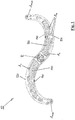
- FIGS 1 to 3 show an embodiment of a washing system 10 according to the invention, the washing system shown comprising a total of two washing arm segments.
- the washing system 10 is designed such that it can be rotated about an axis of rotation R when it is installed and operated in a dishwasher, in particular in a commercial dishwasher.
- the two wash arm segments 100 of the wash system 10 are seen in FIG Figures 1 to 3 , designed as an inverse S or question mark.
- the delivery elements A n are only arranged on one side, namely on the side facing the items to be washed after the washing system has been installed in a dishwasher.
- the delivery element that is closest to the axis of rotation R on a wash arm segment 100 is referred to as delivery element A 1
- the delivery element that is the greatest distance from the axis of rotation R is designated as delivery element A max (in the embodiment shown also delivery element A 10 ). That in the Figures 1 to 3
- the washing system 10 shown rotates when properly installed in a dishwasher, in the view shown in the figures, clockwise.
- each wash arm segment 100 which is in the direction of rotation or the direction of rotation of the wash system 10 or in the direction of movement of the wash arm segment 100, is therefore referred to as the front lateral delimitation 120, while the lateral delimitation, which is in the direction of rotation or direction of rotation of the wash system or in the direction of movement of the Wash arm segment is located at the rear, is referred to as the rear lateral boundary 140 of the respective wash arm segment 100.
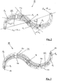
- Fig. 2 illustrates in particular the positioning of the delivery elements A n on the wash arm segments 100 and explains the interior angles ⁇ n .
- each wash arm segment 100 comprises a total of 10 delivery elements A 1 to A 10 , the delivery element A 1 being the delivery element which has the smallest distance r 1 from the axis of rotation R, while the delivery element A 10 (which corresponds to the delivery element A max ) is the delivery element that is at the greatest distance from the axis of rotation R.
- a connecting line between the axis of rotation R and a dispensing element forms an interior angle a with a connecting line between the axis of rotation R and another dispensing element.
- the washing arm segment shown on the left is shown, for example, the interior angle ⁇ 5 , which corresponds to the angle that, at the axis of rotation R, between a connecting line that extends from the axis of rotation R to the dispensing element A 1 and a connecting line that extends between the axis of rotation R and the delivery element A 5 extends, is formed.
- the interior angle ⁇ 5 which corresponds to the angle that, at the axis of rotation R, between a connecting line that extends from the axis of rotation R to the dispensing element A 1 and a connecting line that extends between the axis of rotation R and the delivery element A 5 extends, is formed.
- wash arm segment 100 On the right-hand side shown wash arm segment 100 is shown analogously an interior angle ⁇ 2 , which corresponds to the angle that, on the axis of rotation R, between a connecting line that extends from the axis of rotation R to the dispensing element A 1 and a connecting line that extends between the axis of rotation R and the delivery element A 2 is formed.
- the position of the dispensing element A 1 which is the smallest distance from the axis of rotation R, is therefore defined by the distance r 1 , while the relative positioning of all other dispensing elements A n relative to the first dispensing element A 1 is defined by the respective distance from the axis of rotation R. , namely r n , and by the corresponding interior angle ⁇ n .
- the interior angle ⁇ 1 which is assigned to the first output element A 1 , is always 0 °.
- the position of the delivery element A max which is at the greatest distance from the axis of rotation R, therefore defines the interior angle ⁇ max .
- the interior angle ⁇ max of the wash arm segment 100 which is shown in Fig. 2 shown on the right is greater than 75 ° and in this embodiment is about 80 °.
- two angles can also be defined between two connecting lines that meet in the axis of rotation R, the interior angle ⁇ n in the sense of this invention always being the smaller of the two angles.
- the other, larger angle which, however, was not referred to in the definition of this invention, has a size of 360 ° - ⁇ n .
- FIG. 13 shows a view in which a center line 130 is drawn in for each of the wash arm segments 100.
- the center line is determined in a top view or alternatively in a view from below, i.e. in a view parallel to the axis of rotation R, the center line being arranged in this view so that the distance from the center line is in a plane perpendicular to the axis of rotation R, in which the The center line runs, viewed, to a front lateral delimitation 120 of the wash arm segment is just as large as the distance to a rear lateral delimitation 140 of the wash arm segment 100.
- all the delivery members are in a range of the center line of the Why it is in a range of the center line of the Why it is in a range from the center line 130 starting in a direction towards the front lateral delimitation 120 of the wash arm segment 100.
- all dispensing elements A n are designed in the form of nozzles, the nozzles having an elongated dispensing opening so that a longitudinal axis of each dispensing opening is defined which extends in each case along the longest extent of the dispensing openings.
- the dispensing elements designed as nozzles are designed and arranged in such a way that, on each of the wash arm segments 100, the longitudinal axes of the dispensing openings of most of the dispensing elements A n extend so that they intersect the axis of rotation R.
- two delivery elements namely the delivery elements A 7 and A 9 , are designed in such a way that the longitudinal axes or their extensions do not intersect the axis of rotation R, rather the longitudinal axis of the delivery element A 7 is approximately 45 compared to such an arrangement ° rotated, while the longitudinal axis of the dispensing opening of the dispensing element A 9 is rotated approximately 90 ° with respect to such an orientation.
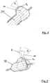
- Figure 4 shows a partial cross section through a wash arm segment of a washing system according to the invention, the partial cross section being guided through an area of the wash arm segment in which a delivery element A n is provided, which in this embodiment is designed as a nozzle.
- the nozzle is designed in such a way that it has an emission region which essentially has the shape of a cone, the opening angle of the cone being denoted by ⁇ 1.
- the opening angle ⁇ 1 can be identical for all delivery elements A n , which are arranged on a wash arm segment 100, but the opening angle can vary from nozzle to nozzle or also in the case of a nozzle as a function of the cutting plane. Preferred opening angles are in a range from 30 ° to 80 °, in particular in a range from 50 ° to 70 °. In the case of the Figure 4 The embodiment shown, the opening angle ⁇ 1 is just under 60 °.
- the dispensing device A n in this embodiment is designed in such a way that a central axis of the opening cone or a main emission direction of the dispensing area runs essentially perpendicularly, that is, parallel to the axis of rotation R.
- Fig. 5 shows another partial cross-section through a wash arm segment 100 of a washing system 10 according to the invention, a dispensing element A n also being provided in this cross-section.
- This delivery element A n also has an essentially conical delivery area, the cone having an opening angle of ⁇ 2 , which, in this embodiment, is just as large as ⁇ 1 , but in other embodiments can also be configured differently from ⁇ 1.
- a central axis of the opening cone or the radiation cone or a main radiation direction of the delivery area is tilted relative to the vertical, i.e. relative to the axis of rotation R, by an angle ⁇ 1 , which in this embodiment is about 30 °.
- the emission characteristics of the delivery elements A n can vary from one another, both by changing the opening angle ⁇ 1 , ⁇ 2 , and by changing the angle ⁇ 1 , at an angle relative to the axis of rotation R, with the nozzles also relative to the central axis, of course 180 can be rotated, which also changes the radiation characteristics in the case of non-symmetrical radiation areas of the nozzle.
Landscapes
- Washing And Drying Of Tableware (AREA)
Claims (15)
- Système de lavage pour un lave-vaisselle, qui comprend un bras de lavage, qui est rotatif autour d'un axe de rotation R, dans lequel le bras de lavage comprend au moins un segment de bras de lavage qui s'étend à partir de l'axe de rotation R,
dans lequel l'au moins un segment de bras de lavage N comprend des éléments de distribution pour la distribution d'un milieu fluide, avec N ≥ 3, dans lequel chaque élément de distribution An est disposé à une distance rn, avec n = 1... N, de l'axe de rotation R,
dans lequel une ligne de liaison entre l'axe de rotation R et un premier élément de distribution A1 de l'au moins un segment de bras de lavage, qui présente la plus courte distance n de tous les éléments de distribution An de ce segment de bras de lavage par rapport à l'axe de rotation R, forme, avec une ligne de liaison entre l'axe de rotation R et chacun des autres éléments de distribution An de ce même segment de bras de lavage, avec n = 2... N, un angle interne αn, avec n = 2... N,
dans lequel un angle interne αn pour chaque élément de distribution An, avec n = 2...N, d'un segment de bras de lavage, est supérieur à un angle interne αn-1 pour un autre élément de distribution An-1, avec n = 2... N, de ce même segment de bras de lavage, lorsque la distance rn entre l'élément de distribution An et l'axe de rotation R est supérieur à la distance rn-1 entre l'élément de distribution An-1 et l'axe de rotation R, caractérisé en ce que les éléments de distribution sont disposés sur le segment de bras de lavage de façon à ce qu'une différence entre deux angles internes αn et αn-1 soit égale à au moins 2° pour deux éléments de distribution différents An et An-1 et
les éléments de distribution sont disposés sur le segment de bras de lavage de façon à ce que l'angle interne αmax pour l'élément de distribution Amax, qui présente, sur le segment de bras de lavage, la distance la plus grande rmax de tous les éléments de distribution de ce segment de bras de lavage par rapport à l'axe de rotation R, soit d'au moins 60°. - Système de lavage selon la revendication 1, caractérisé en ce que les éléments de distribution sont disposés sur un segment de bras de lavage, de façon à ce qu'une différence entre deux angles internes αn et αn-1 pour deux éléments de distribution différents An et An-1 sur un segment de bras de lavage soit d'au moins 3°, de préférence d'au moins 5°.
- Système de lavage selon l'une des revendications précédentes, caractérisé en ce que les éléments de distribution An sont disposés sur un segment de bras de lavage chacun à une distance différente rn de l'axe de rotation R.
- Système de lavage selon l'une des revendications précédentes, caractérisé en ce que le bras de lavage comprend au moins deux segments de bras de lavage, de préférence exactement deux segments de bras de lavage, qui s'étendent de l'axe de rotation R dans différentes directions.
- Système de lavage selon la revendication 4, caractérisé en ce qu'une section transversale du bras de lavage dans un plan perpendiculaire à l'axe de rotation R présente globalement une forme de S ou la forme d'un S inversé.
- Système de lavage selon l'une des revendications 4 à 5, caractérisé en ce que le nombre d'éléments de distribution et/ou la position des éléments de distribution sur un segment de bras de lavage est différent du nombre d'éléments de distribution et/ou de la position des éléments de distribution sur un autre segment de bras de lavage.
- Système de lavage selon l'une des revendications précédentes, caractérisé en ce que chaque segment de bras de lavage comprend un canal d'alimentation conçu sous la forme d'une cavité, pour le logement d'un milieu fluide et pour l'alimentation du milieu fluide vers les éléments de distribution, dans lequel la section transversale du canal d'alimentation dans un plan perpendiculaire à une tangente d'une ligne centrale du segment de bras de lavage se rétrécit lorsque la distance par rapport l'axe de rotation R augmente.
- Système de lavage selon la revendication 7, caractérisé en ce que le rétrécissement du canal d'alimentation a lieu dans une mesure qui est globalement proportionnelle à la diminution d'un débit volumique du milieu fluide, lorsque la distance par rapport à l'axe de rotation augmente, qui est provoquée par la distribution du milieu fluide par les éléments de distribution.
- Système de lavage selon l'une des revendications précédentes, caractérisé en ce que tous les éléments de distribution An d'un segment de bras de lavage au niveau d'une ligne centrale du segment de bras de lavage, qui s'étend dans un plan perpendiculaire à l'axe de rotation R, s'étendent jusqu'à une limitation latérale du segment de bras de lavage, qui se trouve à l'avant dans la direction de déplacement du segment de bras de lavage.
- Système de lavage selon l'une des revendications précédentes, caractérisé en ce qu'au moins un des éléments de distribution, de préférence tous les éléments de distribution, sont conçus comme des buses, dans lequel, de préférence, au moins une buse présente une caractéristique d'émission différente d'une autre buse sur le même segment de bras de lavage.
- Système de lavage selon l'une des revendications précédentes, caractérisé en ce que, dans au moins un segment de bras de lavage, les éléments de distribution sont positionnés de façon à ce que, dans la zone du segment de bras de lavage qui s'étend de l'axe de rotation R jusqu'à la moitié de l'extension radiale maximale du segment de bras de lavage, soient disposés moins d'éléments de distribution que dans la zone du segment de bras de lavage qui s'étend de la moitié de l'extension radiale maximale du segment de bras de lavage jusqu'à l'extension radiale maximale du segment de bras de lavage.
- Système de lavage selon l'une des revendications précédentes, caractérisé en ce que les segments de bras de lavage sont conçus de façon à ce que, dans les zones des segments de bras de lavage qui s'étendent de l'axe de rotation R jusqu'à la moitié de l'extension radiale maximale du système de lavage, soient disposés moins d'éléments de distribution que dans les zones segments de bras de lavage qui s'étendent de la moitié de l'extension radiale maximale du système de lavage jusqu'à l'extension radiale maximale du système de lavage.
- Système de lavage selon l'une des revendications précédentes, caractérisé en ce qu'au moins un élément de distribution An est conçu et disposé sur un segment de bras de lavage de façon à ce qu'une direction d'émission principale ou un axe central de la zone de distribution de l'élément de distribution An soit basculée par rapport à l'axe de rotation R d'un angle (γ1).
- Système de lavage selon l'une des revendications précédentes, caractérisé en ce qu'au moins deux éléments de distribution An sur un segment de bras de lavage sont conçus sous la forme de buses, dans lequel les buses comprennent chacune une ouverture de distribution allongée, dans lequel un axe longitudinal de chacune des ouvertures de distribution est définie, qui s'étend dans la direction de l'extension la plus longue de l'ouverture de distribution, dans lequel les deux éléments de distribution sont disposés de façon à ce que les axes longitudinaux des deux éléments de distribution ne soient pas parallèles entre eux et l'axe longitudinal d'au moins une ouverture de distribution soit disposée de façon à ne pas croiser l'axe de rotation R.
- Lave-vaisselle, plus particulièrement lave-vaisselle professionnel, qui comprend au moins un système de lavage selon l'une des revendications précédentes.
Applications Claiming Priority (1)
| Application Number | Priority Date | Filing Date | Title |
|---|---|---|---|
| DE102015111811.4A DE102015111811B4 (de) | 2015-07-21 | 2015-07-21 | Waschsystem für eine Geschirrspülmaschine, sowie Geschirrspülmaschine mit einem solchen Waschsystem |
Publications (2)
| Publication Number | Publication Date |
|---|---|
| EP3120747A1 EP3120747A1 (fr) | 2017-01-25 |
| EP3120747B1 true EP3120747B1 (fr) | 2021-08-25 |
Family
ID=56497678
Family Applications (1)
| Application Number | Title | Priority Date | Filing Date |
|---|---|---|---|
| EP16180467.9A Active EP3120747B1 (fr) | 2015-07-21 | 2016-07-21 | Système de lavage pour un lave-vaisselle et lave-vaisselle doté d'un tel système de lavage |
Country Status (3)
| Country | Link |
|---|---|
| EP (1) | EP3120747B1 (fr) |
| DE (1) | DE102015111811B4 (fr) |
| ES (1) | ES2890679T3 (fr) |
Cited By (1)
| Publication number | Priority date | Publication date | Assignee | Title |
|---|---|---|---|---|
| EP4400025A1 (fr) * | 2023-01-10 | 2024-07-17 | Illinois Tool Works Inc. | Bras de lavage pour un lave-vaisselle, en particulier un lave-vaisselle industriel, système de bras de lavage doté d'un tel bras de lavage et lave-vaisselle |
Family Cites Families (10)
| Publication number | Priority date | Publication date | Assignee | Title |
|---|---|---|---|---|
| IT1240721B (it) * | 1990-09-06 | 1993-12-17 | Merloni Elettrodomestici Spa | Macchina lavastoviglie perfezionata |
| DE10205008A1 (de) * | 2002-02-07 | 2003-08-21 | Electrolux Home Prod Corp | Geschirrspülmaschine |
| US6869029B2 (en) * | 2002-04-02 | 2005-03-22 | Distinctive Appliances, Inc. | Water spray system for a dishwasher |
| WO2011144540A2 (fr) * | 2010-05-19 | 2011-11-24 | Electrolux Home Products Corporation N.V. | Disposition dans une machine à laver la vaisselle |
| DE102010051218A1 (de) * | 2010-11-12 | 2012-05-16 | Belimed Ag | Wascharm für eine Reinigungsmaschine zum Reinigen von medizinischen, pharmazeutischen und/oder Labor-Utensilien |
| US20120279536A1 (en) * | 2011-05-04 | 2012-11-08 | Whirlpool Corporation | Dishwasher spray arm with diverting valve |
| US20120285496A1 (en) * | 2011-05-09 | 2012-11-15 | General Electric Company | Dishwasher spray assembly |
| US9179818B2 (en) * | 2012-05-01 | 2015-11-10 | General Electric Company | Spray arm assembly for a dishwasher appliance |
| DE102012104026B4 (de) | 2012-05-08 | 2019-01-17 | Winterhalter Gastronom Gmbh | Spülsystem für Geschirrspülmaschinen, sowie Geschirrspülmaschine mit einem solchen Spülsystem |
| CN203447254U (zh) * | 2013-07-10 | 2014-02-26 | 美的集团股份有限公司 | 喷臂水路连接结构和洗碗机 |
-
2015
- 2015-07-21 DE DE102015111811.4A patent/DE102015111811B4/de active Active
-
2016
- 2016-07-21 EP EP16180467.9A patent/EP3120747B1/fr active Active
- 2016-07-21 ES ES16180467T patent/ES2890679T3/es active Active
Non-Patent Citations (1)
| Title |
|---|
| None * |
Cited By (1)
| Publication number | Priority date | Publication date | Assignee | Title |
|---|---|---|---|---|
| EP4400025A1 (fr) * | 2023-01-10 | 2024-07-17 | Illinois Tool Works Inc. | Bras de lavage pour un lave-vaisselle, en particulier un lave-vaisselle industriel, système de bras de lavage doté d'un tel bras de lavage et lave-vaisselle |
Also Published As
| Publication number | Publication date |
|---|---|
| ES2890679T3 (es) | 2022-01-21 |
| DE102015111811B4 (de) | 2017-02-09 |
| EP3120747A1 (fr) | 2017-01-25 |
| DE102015111811A1 (de) | 2017-01-26 |
Similar Documents
| Publication | Publication Date | Title |
|---|---|---|
| DE19832982C2 (de) | Spülvorrichtung für eine Geschirrspülmaschine | |
| DE112005000830B4 (de) | Spender einer Waschmittelzufuhrvorrichtung für eine Waschmaschine | |
| EP2601877B1 (fr) | Lave-vaisselle avec inversion automatique du sens de rotation du bras pulvérisateur | |
| EP2601878B1 (fr) | Lave-vaisselle avec inversion automatique du sens de rotation du bras pulvérisateur | |
| DE19608030C1 (de) | Reinigungsmaschine, insbesondere für Geschirr | |
| DE7024995U (de) | Geschirrspülmaschine | |
| WO2014029451A1 (fr) | Dispositif de consolidation hydrodynamique de non-tissés, tissus ou tricots | |
| DE102005015156A1 (de) | Transportgeschirrspülmaschine und Sprührohr dafür | |
| EP3120747B1 (fr) | Système de lavage pour un lave-vaisselle et lave-vaisselle doté d'un tel système de lavage | |
| EP3727084B1 (fr) | Procede de nettoyage de pinceaux | |
| EP1681976B1 (fr) | Dispositif pour commander des canaux de pulverisation dans des lave-vaisselle | |
| EP2353732B2 (fr) | Barre distributrice | |
| DE69330471T2 (de) | Gerät zum Streuen von Material | |
| DE1926826U (de) | Spruehvorrichtung fuer automatische geschirrspuelmaschinen. | |
| EP2868818B1 (fr) | Système d'évier | |
| EP3815595B1 (fr) | Machine à laver la vaisselle dotée bande transporteuse | |
| EP2695566B1 (fr) | Lave-vaisselle automatique | |
| EP3375564B1 (fr) | Machine-outil et son procédé de fonctionnement | |
| EP3362329B1 (fr) | Installation de lavage de véhicules | |
| DE202013105662U1 (de) | Vorrichtung zur Positionierung einer stehenden Person im Zentrum einer Düsenanordnung | |
| DE2030118C3 (de) | Maschine zum Schleifen und Polieren der gekrümmten Oberfläche eines hohlen Glasgegenstandes, insbesondere des Bildschirmes einer Fernsehröhre | |
| DE2536411C3 (de) | Spülmaschine zum Reinigen von ringförmigen Gegenständen | |
| EP3747340B1 (fr) | Panier pour laves-vaisselles | |
| DE202009017787U1 (de) | Vorrichtung zum Aufbringen einer Oberflächenschicht auf Kerne | |
| DE202017105653U1 (de) | Drahterodiermaschine zum Schneidformen von Keksen |
Legal Events
| Date | Code | Title | Description |
|---|---|---|---|
| PUAI | Public reference made under article 153(3) epc to a published international application that has entered the european phase |
Free format text: ORIGINAL CODE: 0009012 |
|
| STAA | Information on the status of an ep patent application or granted ep patent |
Free format text: STATUS: REQUEST FOR EXAMINATION WAS MADE |
|
| 17P | Request for examination filed |
Effective date: 20161010 |
|
| AK | Designated contracting states |
Kind code of ref document: A1 Designated state(s): AL AT BE BG CH CY CZ DE DK EE ES FI FR GB GR HR HU IE IS IT LI LT LU LV MC MK MT NL NO PL PT RO RS SE SI SK SM TR |
|
| AX | Request for extension of the european patent |
Extension state: BA ME |
|
| STAA | Information on the status of an ep patent application or granted ep patent |
Free format text: STATUS: EXAMINATION IS IN PROGRESS |
|
| 17Q | First examination report despatched |
Effective date: 20170614 |
|
| REG | Reference to a national code |
Ref country code: DE Ref legal event code: R079 Ref document number: 502016013680 Country of ref document: DE Free format text: PREVIOUS MAIN CLASS: A47L0015230000 Ipc: A47L0015420000 |
|
| GRAP | Despatch of communication of intention to grant a patent |
Free format text: ORIGINAL CODE: EPIDOSNIGR1 |
|
| STAA | Information on the status of an ep patent application or granted ep patent |
Free format text: STATUS: GRANT OF PATENT IS INTENDED |
|
| RIC1 | Information provided on ipc code assigned before grant |
Ipc: A47L 15/42 20060101AFI20210203BHEP Ipc: A47L 15/23 20060101ALI20210203BHEP |
|
| INTG | Intention to grant announced |
Effective date: 20210309 |
|
| GRAS | Grant fee paid |
Free format text: ORIGINAL CODE: EPIDOSNIGR3 |
|
| GRAA | (expected) grant |
Free format text: ORIGINAL CODE: 0009210 |
|
| STAA | Information on the status of an ep patent application or granted ep patent |
Free format text: STATUS: THE PATENT HAS BEEN GRANTED |
|
| AK | Designated contracting states |
Kind code of ref document: B1 Designated state(s): AL AT BE BG CH CY CZ DE DK EE ES FI FR GB GR HR HU IE IS IT LI LT LU LV MC MK MT NL NO PL PT RO RS SE SI SK SM TR |
|
| REG | Reference to a national code |
Ref country code: CH Ref legal event code: EP |
|
| REG | Reference to a national code |
Ref country code: DE Ref legal event code: R096 Ref document number: 502016013680 Country of ref document: DE |
|
| REG | Reference to a national code |
Ref country code: IE Ref legal event code: FG4D Free format text: LANGUAGE OF EP DOCUMENT: GERMAN Ref country code: AT Ref legal event code: REF Ref document number: 1422929 Country of ref document: AT Kind code of ref document: T Effective date: 20210915 |
|
| REG | Reference to a national code |
Ref country code: LT Ref legal event code: MG9D |
|
| REG | Reference to a national code |
Ref country code: NL Ref legal event code: MP Effective date: 20210825 |
|
| REG | Reference to a national code |
Ref country code: ES Ref legal event code: FG2A Ref document number: 2890679 Country of ref document: ES Kind code of ref document: T3 Effective date: 20220121 |
|
| PG25 | Lapsed in a contracting state [announced via postgrant information from national office to epo] |
Ref country code: HR Free format text: LAPSE BECAUSE OF FAILURE TO SUBMIT A TRANSLATION OF THE DESCRIPTION OR TO PAY THE FEE WITHIN THE PRESCRIBED TIME-LIMIT Effective date: 20210825 Ref country code: RS Free format text: LAPSE BECAUSE OF FAILURE TO SUBMIT A TRANSLATION OF THE DESCRIPTION OR TO PAY THE FEE WITHIN THE PRESCRIBED TIME-LIMIT Effective date: 20210825 Ref country code: SE Free format text: LAPSE BECAUSE OF FAILURE TO SUBMIT A TRANSLATION OF THE DESCRIPTION OR TO PAY THE FEE WITHIN THE PRESCRIBED TIME-LIMIT Effective date: 20210825 Ref country code: FI Free format text: LAPSE BECAUSE OF FAILURE TO SUBMIT A TRANSLATION OF THE DESCRIPTION OR TO PAY THE FEE WITHIN THE PRESCRIBED TIME-LIMIT Effective date: 20210825 Ref country code: PT Free format text: LAPSE BECAUSE OF FAILURE TO SUBMIT A TRANSLATION OF THE DESCRIPTION OR TO PAY THE FEE WITHIN THE PRESCRIBED TIME-LIMIT Effective date: 20211227 Ref country code: NO Free format text: LAPSE BECAUSE OF FAILURE TO SUBMIT A TRANSLATION OF THE DESCRIPTION OR TO PAY THE FEE WITHIN THE PRESCRIBED TIME-LIMIT Effective date: 20211125 Ref country code: LT Free format text: LAPSE BECAUSE OF FAILURE TO SUBMIT A TRANSLATION OF THE DESCRIPTION OR TO PAY THE FEE WITHIN THE PRESCRIBED TIME-LIMIT Effective date: 20210825 Ref country code: BG Free format text: LAPSE BECAUSE OF FAILURE TO SUBMIT A TRANSLATION OF THE DESCRIPTION OR TO PAY THE FEE WITHIN THE PRESCRIBED TIME-LIMIT Effective date: 20211125 |
|
| PG25 | Lapsed in a contracting state [announced via postgrant information from national office to epo] |
Ref country code: PL Free format text: LAPSE BECAUSE OF FAILURE TO SUBMIT A TRANSLATION OF THE DESCRIPTION OR TO PAY THE FEE WITHIN THE PRESCRIBED TIME-LIMIT Effective date: 20210825 Ref country code: LV Free format text: LAPSE BECAUSE OF FAILURE TO SUBMIT A TRANSLATION OF THE DESCRIPTION OR TO PAY THE FEE WITHIN THE PRESCRIBED TIME-LIMIT Effective date: 20210825 Ref country code: GR Free format text: LAPSE BECAUSE OF FAILURE TO SUBMIT A TRANSLATION OF THE DESCRIPTION OR TO PAY THE FEE WITHIN THE PRESCRIBED TIME-LIMIT Effective date: 20211126 |
|
| PG25 | Lapsed in a contracting state [announced via postgrant information from national office to epo] |
Ref country code: NL Free format text: LAPSE BECAUSE OF FAILURE TO SUBMIT A TRANSLATION OF THE DESCRIPTION OR TO PAY THE FEE WITHIN THE PRESCRIBED TIME-LIMIT Effective date: 20210825 |
|
| PG25 | Lapsed in a contracting state [announced via postgrant information from national office to epo] |
Ref country code: DK Free format text: LAPSE BECAUSE OF FAILURE TO SUBMIT A TRANSLATION OF THE DESCRIPTION OR TO PAY THE FEE WITHIN THE PRESCRIBED TIME-LIMIT Effective date: 20210825 |
|
| REG | Reference to a national code |
Ref country code: DE Ref legal event code: R097 Ref document number: 502016013680 Country of ref document: DE |
|
| PG25 | Lapsed in a contracting state [announced via postgrant information from national office to epo] |
Ref country code: SM Free format text: LAPSE BECAUSE OF FAILURE TO SUBMIT A TRANSLATION OF THE DESCRIPTION OR TO PAY THE FEE WITHIN THE PRESCRIBED TIME-LIMIT Effective date: 20210825 Ref country code: SK Free format text: LAPSE BECAUSE OF FAILURE TO SUBMIT A TRANSLATION OF THE DESCRIPTION OR TO PAY THE FEE WITHIN THE PRESCRIBED TIME-LIMIT Effective date: 20210825 Ref country code: RO Free format text: LAPSE BECAUSE OF FAILURE TO SUBMIT A TRANSLATION OF THE DESCRIPTION OR TO PAY THE FEE WITHIN THE PRESCRIBED TIME-LIMIT Effective date: 20210825 Ref country code: EE Free format text: LAPSE BECAUSE OF FAILURE TO SUBMIT A TRANSLATION OF THE DESCRIPTION OR TO PAY THE FEE WITHIN THE PRESCRIBED TIME-LIMIT Effective date: 20210825 Ref country code: CZ Free format text: LAPSE BECAUSE OF FAILURE TO SUBMIT A TRANSLATION OF THE DESCRIPTION OR TO PAY THE FEE WITHIN THE PRESCRIBED TIME-LIMIT Effective date: 20210825 Ref country code: AL Free format text: LAPSE BECAUSE OF FAILURE TO SUBMIT A TRANSLATION OF THE DESCRIPTION OR TO PAY THE FEE WITHIN THE PRESCRIBED TIME-LIMIT Effective date: 20210825 |
|
| PLBE | No opposition filed within time limit |
Free format text: ORIGINAL CODE: 0009261 |
|
| STAA | Information on the status of an ep patent application or granted ep patent |
Free format text: STATUS: NO OPPOSITION FILED WITHIN TIME LIMIT |
|
| 26N | No opposition filed |
Effective date: 20220527 |
|
| PG25 | Lapsed in a contracting state [announced via postgrant information from national office to epo] |
Ref country code: SI Free format text: LAPSE BECAUSE OF FAILURE TO SUBMIT A TRANSLATION OF THE DESCRIPTION OR TO PAY THE FEE WITHIN THE PRESCRIBED TIME-LIMIT Effective date: 20210825 |
|
| PG25 | Lapsed in a contracting state [announced via postgrant information from national office to epo] |
Ref country code: MC Free format text: LAPSE BECAUSE OF FAILURE TO SUBMIT A TRANSLATION OF THE DESCRIPTION OR TO PAY THE FEE WITHIN THE PRESCRIBED TIME-LIMIT Effective date: 20210825 |
|
| REG | Reference to a national code |
Ref country code: BE Ref legal event code: MM Effective date: 20220731 |
|
| PG25 | Lapsed in a contracting state [announced via postgrant information from national office to epo] |
Ref country code: LU Free format text: LAPSE BECAUSE OF NON-PAYMENT OF DUE FEES Effective date: 20220721 |
|
| PG25 | Lapsed in a contracting state [announced via postgrant information from national office to epo] |
Ref country code: BE Free format text: LAPSE BECAUSE OF NON-PAYMENT OF DUE FEES Effective date: 20220731 |
|
| P01 | Opt-out of the competence of the unified patent court (upc) registered |
Effective date: 20230421 |
|
| PG25 | Lapsed in a contracting state [announced via postgrant information from national office to epo] |
Ref country code: IE Free format text: LAPSE BECAUSE OF NON-PAYMENT OF DUE FEES Effective date: 20220721 |
|
| REG | Reference to a national code |
Ref country code: AT Ref legal event code: MM01 Ref document number: 1422929 Country of ref document: AT Kind code of ref document: T Effective date: 20220721 |
|
| PG25 | Lapsed in a contracting state [announced via postgrant information from national office to epo] |
Ref country code: AT Free format text: LAPSE BECAUSE OF NON-PAYMENT OF DUE FEES Effective date: 20220721 |
|
| PG25 | Lapsed in a contracting state [announced via postgrant information from national office to epo] |
Ref country code: HU Free format text: LAPSE BECAUSE OF FAILURE TO SUBMIT A TRANSLATION OF THE DESCRIPTION OR TO PAY THE FEE WITHIN THE PRESCRIBED TIME-LIMIT; INVALID AB INITIO Effective date: 20160721 |
|
| PG25 | Lapsed in a contracting state [announced via postgrant information from national office to epo] |
Ref country code: MK Free format text: LAPSE BECAUSE OF FAILURE TO SUBMIT A TRANSLATION OF THE DESCRIPTION OR TO PAY THE FEE WITHIN THE PRESCRIBED TIME-LIMIT Effective date: 20210825 Ref country code: CY Free format text: LAPSE BECAUSE OF FAILURE TO SUBMIT A TRANSLATION OF THE DESCRIPTION OR TO PAY THE FEE WITHIN THE PRESCRIBED TIME-LIMIT Effective date: 20210825 |
|
| PG25 | Lapsed in a contracting state [announced via postgrant information from national office to epo] |
Ref country code: MT Free format text: LAPSE BECAUSE OF FAILURE TO SUBMIT A TRANSLATION OF THE DESCRIPTION OR TO PAY THE FEE WITHIN THE PRESCRIBED TIME-LIMIT Effective date: 20210825 |
|
| PGFP | Annual fee paid to national office [announced via postgrant information from national office to epo] |
Ref country code: ES Payment date: 20250812 Year of fee payment: 10 |
|
| PGFP | Annual fee paid to national office [announced via postgrant information from national office to epo] |
Ref country code: DE Payment date: 20250728 Year of fee payment: 10 |
|
| PGFP | Annual fee paid to national office [announced via postgrant information from national office to epo] |
Ref country code: IT Payment date: 20250721 Year of fee payment: 10 |
|
| PGFP | Annual fee paid to national office [announced via postgrant information from national office to epo] |
Ref country code: GB Payment date: 20250722 Year of fee payment: 10 |
|
| PGFP | Annual fee paid to national office [announced via postgrant information from national office to epo] |
Ref country code: FR Payment date: 20250725 Year of fee payment: 10 |
|
| PGFP | Annual fee paid to national office [announced via postgrant information from national office to epo] |
Ref country code: CH Payment date: 20250801 Year of fee payment: 10 |
|
| PG25 | Lapsed in a contracting state [announced via postgrant information from national office to epo] |
Ref country code: TR Free format text: LAPSE BECAUSE OF FAILURE TO SUBMIT A TRANSLATION OF THE DESCRIPTION OR TO PAY THE FEE WITHIN THE PRESCRIBED TIME-LIMIT Effective date: 20210825 |