EP3120747A1 - Système de lavage pour un lave-vaisselle et lave-vaisselle doté d'un tel système de lavage - Google Patents
Système de lavage pour un lave-vaisselle et lave-vaisselle doté d'un tel système de lavage Download PDFInfo
- Publication number
- EP3120747A1 EP3120747A1 EP16180467.9A EP16180467A EP3120747A1 EP 3120747 A1 EP3120747 A1 EP 3120747A1 EP 16180467 A EP16180467 A EP 16180467A EP 3120747 A1 EP3120747 A1 EP 3120747A1
- Authority
- EP
- European Patent Office
- Prior art keywords
- elements
- axis
- rotation
- washing system
- discharge
- Prior art date
- Legal status (The legal status is an assumption and is not a legal conclusion. Google has not performed a legal analysis and makes no representation as to the accuracy of the status listed.)
- Granted
Links
Images


Classifications
-
- A—HUMAN NECESSITIES
- A47—FURNITURE; DOMESTIC ARTICLES OR APPLIANCES; COFFEE MILLS; SPICE MILLS; SUCTION CLEANERS IN GENERAL
- A47L—DOMESTIC WASHING OR CLEANING; SUCTION CLEANERS IN GENERAL
- A47L15/00—Washing or rinsing machines for crockery or tableware
- A47L15/14—Washing or rinsing machines for crockery or tableware with stationary crockery baskets and spraying devices within the cleaning chamber
- A47L15/18—Washing or rinsing machines for crockery or tableware with stationary crockery baskets and spraying devices within the cleaning chamber with movably-mounted spraying devices
- A47L15/22—Rotary spraying devices
- A47L15/23—Rotary spraying devices moved by means of the sprays
-
- A—HUMAN NECESSITIES
- A47—FURNITURE; DOMESTIC ARTICLES OR APPLIANCES; COFFEE MILLS; SPICE MILLS; SUCTION CLEANERS IN GENERAL
- A47L—DOMESTIC WASHING OR CLEANING; SUCTION CLEANERS IN GENERAL
- A47L15/00—Washing or rinsing machines for crockery or tableware
- A47L15/42—Details
- A47L15/4278—Nozzles
Definitions
- the present invention relates to a washing system for a dishwasher and a dishwasher, which is equipped with such a washing system.
- a washing system is typically designed in the form of so-called washing arms, which are acted upon by a fluid medium, usually a cleaning liquid, wherein the fluid medium is then discharged via discharge elements, in particular nozzles, and passed onto the dishes to be cleaned.
- a fluid medium usually a cleaning liquid
- a dishwasher comprises at least one such washing system, but typically several such washing systems or washing arms are placed at different locations in the dishwasher, particularly below and / or above the positions in the dishwasher in which dishes are being positioned for cleaning, for example in corresponding washing baskets.
- a washing system or washing arm is movably mounted, wherein the washing system or the washing arm usually performs a rotational movement about an axis of rotation during operation, so that a washing system or a washing arm covers a certain area within the dishwasher.
- Such a watch system is for example from the DE 10 2012 104 026 A1 known.
- This document discloses a washing system and a dishwasher with a washing system, wherein the dishwasher comprises a plurality of washing systems or washing arms, which are each rotated about an axis of rotation.
- a washing arm for a cleaning machine for cleaning medical and pharmaceutical utensils is known in which the nozzles are formed on both halves of the washing arm so that they are directed in the same direction.
- a dishwashing machine comprising a washing arm having a non-rectilinear main axis with a bend formed to change the direction of flow of the liquid being transported within the washing arm to produce a change in direction To exert pressure on the rinsing arm, so that it is driven in the direction of rotation.
- a further wash arm is known, are arranged on the different spray nozzles, wherein at least a portion of the spray nozzles are adjustable or coverable, so that the individual spray nozzles can also be activated or deactivated, so that the wash arm can be adjusted depending on the loading condition of a dishwasher ,
- a washing system for a dishwasher comprising a wash arm rotatable about a rotation axis R, the wash arm including at least one wash arm segment extending from the rotation axis R.
- the at least one washing arm segment comprises a plurality of dispensing elements for dispensing a fluid medium, wherein according to the invention each washing arm segment comprises at least three dispensing elements, ie comprising a total of N dispensing elements, with N ⁇ 3.
- the individual delivery elements of a greedarmsegments are arranged at different positions of the Wascharmsegments, in such a way that a connecting line between the rotation axis R and a first discharge element A 1 of at least one greedarmsegments having the shortest distance r 1 of all the discharge elements A n this greedarmsegments to the axis of rotation , with a connecting line between the axis of rotation R and another discharge element A n of the same Wascharmsegments forms an internal angle ⁇ n .
- the position of a delivery element A n is therefore determined firstly by its distance r n from the axis of rotation R and secondly by an angular position relative to an angular position of the delivery element A 1 having the shortest distance r 1 of all delivery elements, so that each one Delivery element A n a distance r n from the rotation axis R and an internal angle ⁇ n is assigned.
- an associated interior angle ⁇ n is greater than an interior angle ⁇ n-1 of another delivery element A n-1 of the same wash arm segment, if the distance r n of the delivery element A n from the rotation axis R is greater than the distance r n-1 of the output element A n-1 from the rotation axis R.
- connection line between the rotation axis R and a first output element and a connection line between the rotation axis R and a second output element on the same washer segment, which therefore intersect in the rotation axis R two angles can be defined, which differ from their amount, if the two discharge elements are not arranged so that the two connecting lines extend in parallel.
- an internal angle within the meaning of the invention always means the smaller of these two angles.
- a washing system with dispensing elements arranged in this way has the advantage that the dispensing elements are optimally arranged, so that on the one hand sufficient and good coverage of the areas of the dishwasher in which dishes are positioned for cleaning is ensured, while at the same time ensuring that one Overlapping the delivery areas of the individual delivery elements, typically dispensing cone, greatly reduced and preferably completely avoided, at least up to a certain distance from the dispensing elements, which is relevant for flushing the dishes to be inserted into the dishwasher, in particular the distance of the dispensing elements to the positions in which typically the items to be washed are positioned in the dishwasher, for example in corresponding Waschlcörben.
- the washing system therefore provides an optimized distribution of the dispensing elements on a washing arm segment, moreover, such an arrangement of dispensing elements in a Wascharmsegment also has the advantage that a flow optimization in the supply of the fluid medium is realized within a feed channel within the Wascharmsegments that that leads to an overflow of Nozzle is greatly reduced by the fluid medium within the feed channel.
- a particularly low-loss system is made available which thus saves energy; on the other hand, the constancy and the quality of the delivery of the fluid medium are improved by the delivery elements.
- the washing system of the present invention provides a flow-optimized and thus energy-efficient system which, moreover, with less effort, in particular with lower energy expenditure, delivers improved rinsing results.
- all dispensing elements are arranged on one side of the washing system, namely on the side facing the dishes.
- a washing system which has discharge elements on both sides, that is to say above and below, for example when a washing system is arranged so that items to be washed can be arranged both above and below the washing system.
- the discharge elements are arranged on a greedarmsegment so that an inner angle ⁇ max for the delivery element A max , which has on the Wascharmsegment the greatest distance r max of all delivery elements of this Wascharmsegments from the axis of rotation R, at least 60 °.
- this angle ⁇ max is preferably at least 80 °.
- the angle ⁇ max is in a range of 60 ° to 80 °.
- the dispensing elements are arranged on a greedarmsegment so that a difference between two inner angles ⁇ n and ⁇ n-1 for two different delivery elements A n and A n-1 on a greedarmsegment is at least 2 °. In particularly preferred embodiments, the difference is even at least 3 ° or even at least 5 °.
- the difference between two internal angles is always at least 2 °, but in at least some other delivery elements the difference is greater, for example at least 3 ° or at least 5 °, so that differences between two internal angles between "adjacent" delivery elements, ie between two discharge elements, which have the least difference in terms of their distance r from the axis of rotation R, always be at least 2 °, but in some cases also larger.
- the delivery elements A n on a Wascharmsegment are preferably in each case at different distances r n from the rotation axis R. arranged, which allows a particularly preferred distribution of the dispensing elements in the radial direction and therefore enhances the above effects.
- the wash arm comprises at least two Wascharmsegmente extending from the axis of rotation R in different directions, wherein preferably exactly two Wascharmsegmente are provided which extend from the axis of rotation R in different directions, in particular in opposite directions.
- the wash arm represents a particularly preferred weight distribution about the axis of rotation R, which is favorable for the rotational movement.
- the distribution and the interaction of the delivery elements is supported on the individual Wascharmsegmente in a particularly advantageous manner, so that a good rinsing result can be achieved.
- the washing system is formed so that a cross section of the washing arm is formed in a plane perpendicular to the rotation axis R is substantially S-shaped.
- the washing arm for example, in a plan view, that is, in a view of the wash arm in the direction of the axis of rotation, S-shaped.
- the wash arm S-shaped or in the form of an inverse or mirror-like S is formed.
- Such a design of the washing arm causes the washing arm, taking into account the special arrangement of the dispensing elements according to this invention, can be produced with low material costs and thus with low weight.
- the internal angle ⁇ max for the delivery element A max which has the largest distance r max on a Wascharmsegment, is very large, for example 40 ° or more
- this plays an increased role which is particularly clear in that the (imaginary) connecting line between the axis of rotation R and the delivery element A max , seen in plan view, that is to say in the direction of the axis of rotation R, largely extends over areas runs, which are not above or below the Wascharmsegment, ie in this area no material of the Wascharmsegments is present, which reduces the total weight.
- the number of the dispensing element and / or the position of the dispensing elements on a wash arm segment is different than the number and / or position of dispensing elements on another wash arm segment of the washing system.
- the individual Wascharmsegmente with respect to the distance r n and the inner angle ⁇ n are formed identical, however, a different arrangement of the discharge elements on individual Wascharmsegmenten causes the items to be washed by each of the Wascharmsegmente different with the fluid medium is applied, which further improves the rinsing result.
- each wash arm segment comprises a feed channel formed as a cavity for receiving a fluid medium and for delivering the fluid medium to the dispensing elements, wherein the feed channel is configured such that the cross section of the feed channel is in a plane perpendicular to a tangent of a centerline of the feed line Wascharmsegments with increasing distance from the rotation axis R tapers.
- the taper can be continuous, but it is also possible that a gradual taper is provided, it is also possible that the taper is partially continuous and partly via steps.
- the center line is to be understood as a line which, in a plan view of the washing system in the direction of the axis of rotation R, extends from the axis of rotation R in a plane perpendicular to the axis of rotation R in both directions of the extension Wascharmsegmente extends so that the distance between the center line to a front edge of the Whyarmsegments is the same as the distance of the center line to a rear edge of the Wascharmsegments.
- the center line therefore divides the Whyarmsegmente, with respect to a cross-sectional plane or viewing plane which is perpendicular to the axis of rotation R, in two substantially equal parts.
- This embodiment has the advantage that as uniform as possible flow velocities are generated, so that turbulences within the feed channel are largely avoided.
- the taper of the feed channel is formed with increasing distance from the axis of rotation to an extent substantially proportional to the decrease in a volume flow of the fluid medium with increasing distance from the axis of rotation caused by the delivery of the fluid through the delivery elements ,
- This ensures particularly effective that the flow rate within the feed channel remains largely constant.
- the resulting avoidance or at least reduction of turbulence on the one hand leads to the fact that the washing system is energetically more favorable, moreover, that the discharge characteristic of the delivery elements can be controlled and maintained particularly accurately, furthermore very small fluctuations of the discharge characteristic arise.
- all of the dispenser elements of the wash arm segment are disposed in a region from a centerline of the wash arm segment to a side boundary of the wash arm segment which is forward in the direction of rotation of the wash arm or in the direction of movement of a wash arm segment.
- This arrangement of the dispensing elements in an edge region has, in particular, the effect of further reducing an overflow of the dispensing elements by the fluid medium in the feed channel, which further improves the energy efficiency and the desired dishwashing result.
- the discharge elements are formed as nozzles, wherein furthermore preferably at least not all nozzles of a Whyarmsegments or a washing system have the same emission characteristics.
- the emission characteristic of a nozzle can be influenced on the one hand by the spatial positioning and the position of the nozzle.
- the radiation region which is typically a radiation cone or a radiation fan, may be substantially rotationally symmetrical, it may also not be rotationally symmetrical. so that a rotation of the nozzle around its axes changes the emission characteristics.
- a selection of different radiation characteristics of nozzles therefore makes it possible, in connection with the particular positioning of the dispensing elements on a washing arm segment, to ensure good coverage of the various areas of the dishwasher, for example also to arrange dispensing elements more densely, nevertheless overlapping the irradiation areas and negatively influencing each other Avoid radiation, which would be caused by it.
- the dispensing elements are arranged more densely in an outer region of the Wascharmsegments than in an inner region of the Whyarmsegments. This is preferred because due to the rotational movement of the washing system during the flushing operation, the radially outer regions must cover a larger area and a larger area than the radially inner areas. In this way, a uniformly good dishwashing result is achieved, regardless of where in the dishwasher the dishes are located, for example in an outer area of a washing basket or in an inner area.
- Such compaction of delivery elements in an outer region can be provided for both a single Wascharmsegment, but a compression in an outer region is particularly preferred in terms of several, cooperating Wascharmsegmente or an entire washing system with different Wascharmsegmenten.
- At least one dispensing element A n is formed and arranged on a Wascharmsegment that a Schoabstrahlraum or a central axis of the dispensing area is tilted relative to the axis of rotation R by an angle ( ⁇ 1 ).
- At least two dispensing elements A n are formed as nozzles on a washing arm segment, the nozzles each having an elongate dispensing opening so as to define a longitudinal axis of each dispensing opening extending in the direction of the longest extension of the dispensing opening wherein the two dispensing elements are arranged so that the longitudinal axes of the two dispensing elements are not parallel to one another and a longitudinal axis of at least one dispensing opening is such that it or its extension does not intersect the axis of rotation R.
- the present invention also relates to a dishwasher, in particular a commercial dishwasher, comprising at least one washing system according to one of the preceding claims.
- a dishwasher generally comprises a plurality of washing systems, which are preferably arranged below and / or above, for example, washing baskets in which items to be washed can be inserted inside a dishwasher.
- a particularly preferred dishwashing machine comprises, for example, two rinse baskets, wherein a first washing system is arranged under a lower rinsing basket, while a second washing system is arranged between the two rinsing baskets, and where appropriate additionally a further washing system is arranged above the upper rinsing basket.
- the washing system which is arranged under the lower washing basket, so that items to be washed can be positioned only above the washing system, dispensing elements, in particular nozzles, only on its upper side.
- a washing system that is arranged so that items to be washed can only be positioned under this washing system in the dishwasher, dispensing elements only on its underside. Washing systems arranged so that items to be washed can be positioned both above and below preferably have delivery elements both on the top side and on the bottom side.
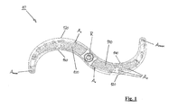
- FIGS. 1 to 3 show an embodiment of a washing system 10 according to the invention, wherein the washing system shown comprises a total of two Wascharmsegmente.
- the washing system 10 is designed so that it can be rotated about an axis of rotation R when it is installed and operated in a dishwasher, in particular in a commercial dishwasher.
- the two Wascharmsegmente 100 of the washing system 10 are, in the view of FIGS. 1 to 3 , formed as an inverse S or question mark.
- the discharge elements A n are arranged only on one side, namely on the after installation of the washing system in a dishwasher facing the items to be washed.
- the delivery element which has the smallest distance to the rotation axis R on a wash arm segment 100, is referred to as delivery element A 1
- the delivery element having the greatest distance from the rotation axis R is referred to as delivery element A max (in the illustrated embodiment also delivery element A 10 ). That in the FIGS. 1 to 3 shown washing system 10 rotates when properly installed in a dishwasher, in the view shown in the figures, in a clockwise direction.
- each Wascharmsegments 100 which is in the direction of rotation or direction of rotation of the washing system 10 or in the direction of movement of Wascharmsegments 100 front, is therefore referred to as the front lateral boundary 120, while the lateral boundary, in the direction of rotation or direction of rotation of the washing system or in the direction of movement of Wascharmsegements behind is, as the rear side boundary 140 of the respective Wascharmsegments 100 is designated.
- Fig. 2 illustrates in particular the positioning of the discharge elements A n on the Wascharmsegmenten 100 and explains the inner angle ⁇ n .
- each Wascharmsegment 100 comprises a total of 10 dispensing elements A 1 to A 10 , wherein the dispensing element A 1 is the dispensing element having the smallest distance r 1 from the axis of rotation R, while the dispensing element A 10 (corresponding to the dispensing element A max ) is the dispensing element that has the greatest distance from the axis of rotation R.
- a connecting line between the rotation axis R and a delivery element forms an inner angle ⁇ with a connecting line between the rotation axis R and another delivery element.
- the inner angle ⁇ 5 is shown, which corresponds to the angle which, at the axis of rotation R, between a connecting line extending from the axis of rotation R to the discharge element A 1 and a connecting line extending between the axis of rotation R and the discharge element A 5 extends is formed.
- an inner angle ⁇ 2 is shown, which corresponds to the angle which, at the axis of rotation R, between a connecting line extending from the axis of rotation R to the discharge element A 1 and a connecting line extending between the axis of rotation R and the delivery element A 2 extends is formed.
- the position of the delivery element A 1 which has the smallest distance to the rotation axis R, is therefore defined by the distance r 1 , while the relative positioning of all other delivery elements A n is defined relative to the first delivery element A 1 , by the respective distance to the rotation axis R. , namely r n , and by the corresponding internal angle ⁇ n .
- the internal angle ⁇ 1 which is assigned to the first output element A 1 , always 0 °.
- the position of the delivery element A max which has the greatest distance from the axis of rotation R, therefore defines the internal angle ⁇ max .
- the wash arm segment 100 incorporated in FIG Fig. 2 on the left side, a total of 10 discharge elements, and the discharge element A 10 A max , which has the greatest distance from the axis of rotation R, includes an internal angle ⁇ max , which, in this embodiment, is greater than 60 °, and in this embodiment is between 61 ° and 62 °.
- the inner angle ⁇ max of the Wascharmsegments 100, the in Fig. 2 is shown on the right side is greater than 75 ° and in this embodiment is about 80 °.
- FIG. 12 is a view showing a centerline 130 for each of the wash arm segments 100.
- the center line is determined in a plan view or alternatively in a bottom view, ie in a view parallel to the axis of rotation R, in this view, the center line is arranged so that the distance of the center line, in a plane perpendicular to the axis of rotation R, in which the When viewed from a centerline, the front side boundary 120 of the wash arm segment is exactly the same as the distance to a rear lateral boundary 140 of the wash arm segment 100.
- all dispensing elements A n are in the form of nozzles, the nozzles having an elongated dispensing opening so as to define a longitudinal axis of each dispensing opening extending along the longest extent of the dispensing openings.
- the dispensing elements formed as nozzles are configured and arranged such that, on each of the wash arm segments 100, the longitudinal axes of the dispensing openings of most dispensing elements A n extend to intersect the axis of rotation R.
- two delivery elements namely in each case the discharge elements A 7 and A 9 , formed so that the longitudinal axes or their extensions do not intersect the axis of rotation R, but the longitudinal axis of the discharge element A 7 to such an arrangement in about 45th ° rotated while the longitudinal axis of the discharge opening of the discharge element A 9 is rotated relative to such an orientation in about 90 °.
- FIG. 4 shows a partial cross section through a Wascharmsegment a washing system according to the invention, wherein the partial cross section is guided through a portion of the Wascharmsegments in which a discharge element A n is provided, which is formed in this embodiment as a nozzle.
- the nozzle is formed so as to have a radiating area which has substantially the shape of a cone, the opening angle of the cone being designated by ⁇ 1 .
- the opening angle ⁇ 1 can be identical for all delivery elements A n arranged on a wash arm segment 100, but the opening angle can vary from nozzle to nozzle or even at a nozzle depending on the sectional plane. Preferred opening angles are in a range of 30 ° to 80 °, in particular in a range of 50 ° to 70 °. When in the FIG. 4 shown embodiment, the opening angle ⁇ 1 is almost 60 °.
- the dispensing device A n is formed in this embodiment so that a central axis of the opening cone or a main emission direction of the delivery region is substantially perpendicular, ie parallel to the axis of rotation R.
- Fig. 5 shows another partial cross section through a Wascharmsegment 100 of a washing system 10 according to the invention, wherein in this cross section also a discharge element A n is provided.
- This discharge element A n also has a substantially cone-shaped delivery region, wherein the cone has an opening angle of ⁇ 2 , which, in this embodiment, is the same size as ⁇ 1 , but in other embodiments can also be different from ⁇ 1 .
- Fig. 5 it can be seen, however, is a central axis of the opening cone or the Abstrahlkegels or a main emission of the dispensing area relative to the vertical, ie relative to the rotation axis R, tilted, by an angle ⁇ 1 , which is about 30 ° in this embodiment.
- the radiation characteristics of the output elements A n can vary from one another, both by changes in the opening angle ⁇ 1 , ⁇ 2 , and by changing the angle ⁇ 1 , at an angle relative to the rotation axis R, of course, the nozzles also relative to the central axis 180 can be rotated, which also changes the radiation characteristic at non-symmetrical radiation areas of the nozzle.
Landscapes
- Washing And Drying Of Tableware (AREA)
Applications Claiming Priority (1)
| Application Number | Priority Date | Filing Date | Title |
|---|---|---|---|
| DE102015111811.4A DE102015111811B4 (de) | 2015-07-21 | 2015-07-21 | Waschsystem für eine Geschirrspülmaschine, sowie Geschirrspülmaschine mit einem solchen Waschsystem |
Publications (2)
| Publication Number | Publication Date |
|---|---|
| EP3120747A1 true EP3120747A1 (fr) | 2017-01-25 |
| EP3120747B1 EP3120747B1 (fr) | 2021-08-25 |
Family
ID=56497678
Family Applications (1)
| Application Number | Title | Priority Date | Filing Date |
|---|---|---|---|
| EP16180467.9A Active EP3120747B1 (fr) | 2015-07-21 | 2016-07-21 | Système de lavage pour un lave-vaisselle et lave-vaisselle doté d'un tel système de lavage |
Country Status (3)
| Country | Link |
|---|---|
| EP (1) | EP3120747B1 (fr) |
| DE (1) | DE102015111811B4 (fr) |
| ES (1) | ES2890679T3 (fr) |
Families Citing this family (1)
| Publication number | Priority date | Publication date | Assignee | Title |
|---|---|---|---|---|
| DE102023100424B4 (de) * | 2023-01-10 | 2025-10-16 | Illinois Tool Works Inc. | Wascharm für eine insbesondere gewerbliche spülmaschine, wascharmsystem mit einem solchen wascharm sowie spülmaschine |
Citations (10)
| Publication number | Priority date | Publication date | Assignee | Title |
|---|---|---|---|---|
| EP0474127A1 (fr) | 1990-09-06 | 1992-03-11 | MERLONI ELETTRODOMESTICI S.p.A. | Machine à laver la vaisselle ameliorée |
| EP1334687A1 (fr) | 2002-02-07 | 2003-08-13 | Electrolux Home Products Corporation N.V. | Lave-vaisselle |
| US20030192578A1 (en) * | 2002-04-02 | 2003-10-16 | Distinctive Appliances, Inc. | Water spray system for a dishwasher |
| DE102010051218A1 (de) | 2010-11-12 | 2012-05-16 | Belimed Ag | Wascharm für eine Reinigungsmaschine zum Reinigen von medizinischen, pharmazeutischen und/oder Labor-Utensilien |
| US20120279536A1 (en) * | 2011-05-04 | 2012-11-08 | Whirlpool Corporation | Dishwasher spray arm with diverting valve |
| US20120285496A1 (en) * | 2011-05-09 | 2012-11-15 | General Electric Company | Dishwasher spray assembly |
| US20130206190A1 (en) | 2010-05-19 | 2013-08-15 | Electrolux Home Products Corporation N.V. | Arrangement in a dishwasher |
| US20130291908A1 (en) * | 2012-05-01 | 2013-11-07 | General Electric Company | Spray arm assembly for a dishwasher appliance |
| DE102012104026A1 (de) | 2012-05-08 | 2013-11-14 | Winterhalter Gastronom Gmbh | Spülsystem für Geschirrspülmaschinen, sowie Geschirrspülmaschine mit einem solchen Spülsystem |
| CN203447254U (zh) * | 2013-07-10 | 2014-02-26 | 美的集团股份有限公司 | 喷臂水路连接结构和洗碗机 |
-
2015
- 2015-07-21 DE DE102015111811.4A patent/DE102015111811B4/de active Active
-
2016
- 2016-07-21 EP EP16180467.9A patent/EP3120747B1/fr active Active
- 2016-07-21 ES ES16180467T patent/ES2890679T3/es active Active
Patent Citations (10)
| Publication number | Priority date | Publication date | Assignee | Title |
|---|---|---|---|---|
| EP0474127A1 (fr) | 1990-09-06 | 1992-03-11 | MERLONI ELETTRODOMESTICI S.p.A. | Machine à laver la vaisselle ameliorée |
| EP1334687A1 (fr) | 2002-02-07 | 2003-08-13 | Electrolux Home Products Corporation N.V. | Lave-vaisselle |
| US20030192578A1 (en) * | 2002-04-02 | 2003-10-16 | Distinctive Appliances, Inc. | Water spray system for a dishwasher |
| US20130206190A1 (en) | 2010-05-19 | 2013-08-15 | Electrolux Home Products Corporation N.V. | Arrangement in a dishwasher |
| DE102010051218A1 (de) | 2010-11-12 | 2012-05-16 | Belimed Ag | Wascharm für eine Reinigungsmaschine zum Reinigen von medizinischen, pharmazeutischen und/oder Labor-Utensilien |
| US20120279536A1 (en) * | 2011-05-04 | 2012-11-08 | Whirlpool Corporation | Dishwasher spray arm with diverting valve |
| US20120285496A1 (en) * | 2011-05-09 | 2012-11-15 | General Electric Company | Dishwasher spray assembly |
| US20130291908A1 (en) * | 2012-05-01 | 2013-11-07 | General Electric Company | Spray arm assembly for a dishwasher appliance |
| DE102012104026A1 (de) | 2012-05-08 | 2013-11-14 | Winterhalter Gastronom Gmbh | Spülsystem für Geschirrspülmaschinen, sowie Geschirrspülmaschine mit einem solchen Spülsystem |
| CN203447254U (zh) * | 2013-07-10 | 2014-02-26 | 美的集团股份有限公司 | 喷臂水路连接结构和洗碗机 |
Also Published As
| Publication number | Publication date |
|---|---|
| ES2890679T3 (es) | 2022-01-21 |
| DE102015111811B4 (de) | 2017-02-09 |
| EP3120747B1 (fr) | 2021-08-25 |
| DE102015111811A1 (de) | 2017-01-26 |
Similar Documents
| Publication | Publication Date | Title |
|---|---|---|
| EP3372064B1 (fr) | Tour de distribution d'une machine agricole, machine agricole et procédé de fonctionnement d'une telle machine agricole | |
| EP1928609B1 (fr) | Pommeau de douche | |
| EP2192852A1 (fr) | Lave-vaisselle | |
| EP2990530B1 (fr) | Engin doté de parois arrieres de reservoir décalées | |
| DE7024995U (de) | Geschirrspülmaschine | |
| WO2014029451A1 (fr) | Dispositif de consolidation hydrodynamique de non-tissés, tissus ou tricots | |
| EP2601877A2 (fr) | Lave-vaisselle avec inversion automatique du sens de rotation du bras pulvérisateur | |
| DE202013101201U1 (de) | Brausevorrichtung | |
| EP1707100B1 (fr) | Lave-vaisselle à convoyeur et tube de pulvérisation associé | |
| EP2601878A2 (fr) | Lave-vaisselle avec inversion automatique du sens de rotation du bras pulvérisateur | |
| DE202015008663U1 (de) | Mehrfach-Klingen Dosierungsventil | |
| WO2015024648A1 (fr) | Barre de tamis profilée et dispositif de tamisage à barres de tamis profilées | |
| DE102015111811B4 (de) | Waschsystem für eine Geschirrspülmaschine, sowie Geschirrspülmaschine mit einem solchen Waschsystem | |
| DE102014107039A1 (de) | Einspülbehälter für eine Feldspritze | |
| EP1673000B1 (fr) | Lave-vaisselle a canaux de pulverisation integres | |
| EP1681976B1 (fr) | Dispositif pour commander des canaux de pulverisation dans des lave-vaisselle | |
| DE102012104026B4 (de) | Spülsystem für Geschirrspülmaschinen, sowie Geschirrspülmaschine mit einem solchen Spülsystem | |
| EP2353732B1 (fr) | Barre distributrice | |
| DE1926826U (de) | Spruehvorrichtung fuer automatische geschirrspuelmaschinen. | |
| EP2868818B1 (fr) | Système d'évier | |
| DE20201339U1 (de) | Futtermischer | |
| EP3815595B1 (fr) | Machine à laver la vaisselle dotée bande transporteuse | |
| AT506464B1 (de) | Vorrichtung zum befüllen eines lagerraumes mit stückeligem brennstoff | |
| DE202009017787U1 (de) | Vorrichtung zum Aufbringen einer Oberflächenschicht auf Kerne | |
| DE2745095C2 (de) | Spritzverteilerkopf |
Legal Events
| Date | Code | Title | Description |
|---|---|---|---|
| PUAI | Public reference made under article 153(3) epc to a published international application that has entered the european phase |
Free format text: ORIGINAL CODE: 0009012 |
|
| STAA | Information on the status of an ep patent application or granted ep patent |
Free format text: STATUS: REQUEST FOR EXAMINATION WAS MADE |
|
| 17P | Request for examination filed |
Effective date: 20161010 |
|
| AK | Designated contracting states |
Kind code of ref document: A1 Designated state(s): AL AT BE BG CH CY CZ DE DK EE ES FI FR GB GR HR HU IE IS IT LI LT LU LV MC MK MT NL NO PL PT RO RS SE SI SK SM TR |
|
| AX | Request for extension of the european patent |
Extension state: BA ME |
|
| STAA | Information on the status of an ep patent application or granted ep patent |
Free format text: STATUS: EXAMINATION IS IN PROGRESS |
|
| 17Q | First examination report despatched |
Effective date: 20170614 |
|
| REG | Reference to a national code |
Ref country code: DE Ref legal event code: R079 Ref document number: 502016013680 Country of ref document: DE Free format text: PREVIOUS MAIN CLASS: A47L0015230000 Ipc: A47L0015420000 |
|
| GRAP | Despatch of communication of intention to grant a patent |
Free format text: ORIGINAL CODE: EPIDOSNIGR1 |
|
| STAA | Information on the status of an ep patent application or granted ep patent |
Free format text: STATUS: GRANT OF PATENT IS INTENDED |
|
| RIC1 | Information provided on ipc code assigned before grant |
Ipc: A47L 15/42 20060101AFI20210203BHEP Ipc: A47L 15/23 20060101ALI20210203BHEP |
|
| INTG | Intention to grant announced |
Effective date: 20210309 |
|
| GRAS | Grant fee paid |
Free format text: ORIGINAL CODE: EPIDOSNIGR3 |
|
| GRAA | (expected) grant |
Free format text: ORIGINAL CODE: 0009210 |
|
| STAA | Information on the status of an ep patent application or granted ep patent |
Free format text: STATUS: THE PATENT HAS BEEN GRANTED |
|
| AK | Designated contracting states |
Kind code of ref document: B1 Designated state(s): AL AT BE BG CH CY CZ DE DK EE ES FI FR GB GR HR HU IE IS IT LI LT LU LV MC MK MT NL NO PL PT RO RS SE SI SK SM TR |
|
| REG | Reference to a national code |
Ref country code: CH Ref legal event code: EP |
|
| REG | Reference to a national code |
Ref country code: DE Ref legal event code: R096 Ref document number: 502016013680 Country of ref document: DE |
|
| REG | Reference to a national code |
Ref country code: IE Ref legal event code: FG4D Free format text: LANGUAGE OF EP DOCUMENT: GERMAN Ref country code: AT Ref legal event code: REF Ref document number: 1422929 Country of ref document: AT Kind code of ref document: T Effective date: 20210915 |
|
| REG | Reference to a national code |
Ref country code: LT Ref legal event code: MG9D |
|
| REG | Reference to a national code |
Ref country code: NL Ref legal event code: MP Effective date: 20210825 |
|
| REG | Reference to a national code |
Ref country code: ES Ref legal event code: FG2A Ref document number: 2890679 Country of ref document: ES Kind code of ref document: T3 Effective date: 20220121 |
|
| PG25 | Lapsed in a contracting state [announced via postgrant information from national office to epo] |
Ref country code: HR Free format text: LAPSE BECAUSE OF FAILURE TO SUBMIT A TRANSLATION OF THE DESCRIPTION OR TO PAY THE FEE WITHIN THE PRESCRIBED TIME-LIMIT Effective date: 20210825 Ref country code: RS Free format text: LAPSE BECAUSE OF FAILURE TO SUBMIT A TRANSLATION OF THE DESCRIPTION OR TO PAY THE FEE WITHIN THE PRESCRIBED TIME-LIMIT Effective date: 20210825 Ref country code: SE Free format text: LAPSE BECAUSE OF FAILURE TO SUBMIT A TRANSLATION OF THE DESCRIPTION OR TO PAY THE FEE WITHIN THE PRESCRIBED TIME-LIMIT Effective date: 20210825 Ref country code: FI Free format text: LAPSE BECAUSE OF FAILURE TO SUBMIT A TRANSLATION OF THE DESCRIPTION OR TO PAY THE FEE WITHIN THE PRESCRIBED TIME-LIMIT Effective date: 20210825 Ref country code: PT Free format text: LAPSE BECAUSE OF FAILURE TO SUBMIT A TRANSLATION OF THE DESCRIPTION OR TO PAY THE FEE WITHIN THE PRESCRIBED TIME-LIMIT Effective date: 20211227 Ref country code: NO Free format text: LAPSE BECAUSE OF FAILURE TO SUBMIT A TRANSLATION OF THE DESCRIPTION OR TO PAY THE FEE WITHIN THE PRESCRIBED TIME-LIMIT Effective date: 20211125 Ref country code: LT Free format text: LAPSE BECAUSE OF FAILURE TO SUBMIT A TRANSLATION OF THE DESCRIPTION OR TO PAY THE FEE WITHIN THE PRESCRIBED TIME-LIMIT Effective date: 20210825 Ref country code: BG Free format text: LAPSE BECAUSE OF FAILURE TO SUBMIT A TRANSLATION OF THE DESCRIPTION OR TO PAY THE FEE WITHIN THE PRESCRIBED TIME-LIMIT Effective date: 20211125 |
|
| PG25 | Lapsed in a contracting state [announced via postgrant information from national office to epo] |
Ref country code: PL Free format text: LAPSE BECAUSE OF FAILURE TO SUBMIT A TRANSLATION OF THE DESCRIPTION OR TO PAY THE FEE WITHIN THE PRESCRIBED TIME-LIMIT Effective date: 20210825 Ref country code: LV Free format text: LAPSE BECAUSE OF FAILURE TO SUBMIT A TRANSLATION OF THE DESCRIPTION OR TO PAY THE FEE WITHIN THE PRESCRIBED TIME-LIMIT Effective date: 20210825 Ref country code: GR Free format text: LAPSE BECAUSE OF FAILURE TO SUBMIT A TRANSLATION OF THE DESCRIPTION OR TO PAY THE FEE WITHIN THE PRESCRIBED TIME-LIMIT Effective date: 20211126 |
|
| PG25 | Lapsed in a contracting state [announced via postgrant information from national office to epo] |
Ref country code: NL Free format text: LAPSE BECAUSE OF FAILURE TO SUBMIT A TRANSLATION OF THE DESCRIPTION OR TO PAY THE FEE WITHIN THE PRESCRIBED TIME-LIMIT Effective date: 20210825 |
|
| PG25 | Lapsed in a contracting state [announced via postgrant information from national office to epo] |
Ref country code: DK Free format text: LAPSE BECAUSE OF FAILURE TO SUBMIT A TRANSLATION OF THE DESCRIPTION OR TO PAY THE FEE WITHIN THE PRESCRIBED TIME-LIMIT Effective date: 20210825 |
|
| REG | Reference to a national code |
Ref country code: DE Ref legal event code: R097 Ref document number: 502016013680 Country of ref document: DE |
|
| PG25 | Lapsed in a contracting state [announced via postgrant information from national office to epo] |
Ref country code: SM Free format text: LAPSE BECAUSE OF FAILURE TO SUBMIT A TRANSLATION OF THE DESCRIPTION OR TO PAY THE FEE WITHIN THE PRESCRIBED TIME-LIMIT Effective date: 20210825 Ref country code: SK Free format text: LAPSE BECAUSE OF FAILURE TO SUBMIT A TRANSLATION OF THE DESCRIPTION OR TO PAY THE FEE WITHIN THE PRESCRIBED TIME-LIMIT Effective date: 20210825 Ref country code: RO Free format text: LAPSE BECAUSE OF FAILURE TO SUBMIT A TRANSLATION OF THE DESCRIPTION OR TO PAY THE FEE WITHIN THE PRESCRIBED TIME-LIMIT Effective date: 20210825 Ref country code: EE Free format text: LAPSE BECAUSE OF FAILURE TO SUBMIT A TRANSLATION OF THE DESCRIPTION OR TO PAY THE FEE WITHIN THE PRESCRIBED TIME-LIMIT Effective date: 20210825 Ref country code: CZ Free format text: LAPSE BECAUSE OF FAILURE TO SUBMIT A TRANSLATION OF THE DESCRIPTION OR TO PAY THE FEE WITHIN THE PRESCRIBED TIME-LIMIT Effective date: 20210825 Ref country code: AL Free format text: LAPSE BECAUSE OF FAILURE TO SUBMIT A TRANSLATION OF THE DESCRIPTION OR TO PAY THE FEE WITHIN THE PRESCRIBED TIME-LIMIT Effective date: 20210825 |
|
| PLBE | No opposition filed within time limit |
Free format text: ORIGINAL CODE: 0009261 |
|
| STAA | Information on the status of an ep patent application or granted ep patent |
Free format text: STATUS: NO OPPOSITION FILED WITHIN TIME LIMIT |
|
| 26N | No opposition filed |
Effective date: 20220527 |
|
| PG25 | Lapsed in a contracting state [announced via postgrant information from national office to epo] |
Ref country code: SI Free format text: LAPSE BECAUSE OF FAILURE TO SUBMIT A TRANSLATION OF THE DESCRIPTION OR TO PAY THE FEE WITHIN THE PRESCRIBED TIME-LIMIT Effective date: 20210825 |
|
| PG25 | Lapsed in a contracting state [announced via postgrant information from national office to epo] |
Ref country code: MC Free format text: LAPSE BECAUSE OF FAILURE TO SUBMIT A TRANSLATION OF THE DESCRIPTION OR TO PAY THE FEE WITHIN THE PRESCRIBED TIME-LIMIT Effective date: 20210825 |
|
| REG | Reference to a national code |
Ref country code: BE Ref legal event code: MM Effective date: 20220731 |
|
| PG25 | Lapsed in a contracting state [announced via postgrant information from national office to epo] |
Ref country code: LU Free format text: LAPSE BECAUSE OF NON-PAYMENT OF DUE FEES Effective date: 20220721 |
|
| PG25 | Lapsed in a contracting state [announced via postgrant information from national office to epo] |
Ref country code: BE Free format text: LAPSE BECAUSE OF NON-PAYMENT OF DUE FEES Effective date: 20220731 |
|
| P01 | Opt-out of the competence of the unified patent court (upc) registered |
Effective date: 20230421 |
|
| PG25 | Lapsed in a contracting state [announced via postgrant information from national office to epo] |
Ref country code: IE Free format text: LAPSE BECAUSE OF NON-PAYMENT OF DUE FEES Effective date: 20220721 |
|
| REG | Reference to a national code |
Ref country code: AT Ref legal event code: MM01 Ref document number: 1422929 Country of ref document: AT Kind code of ref document: T Effective date: 20220721 |
|
| PG25 | Lapsed in a contracting state [announced via postgrant information from national office to epo] |
Ref country code: AT Free format text: LAPSE BECAUSE OF NON-PAYMENT OF DUE FEES Effective date: 20220721 |
|
| PG25 | Lapsed in a contracting state [announced via postgrant information from national office to epo] |
Ref country code: HU Free format text: LAPSE BECAUSE OF FAILURE TO SUBMIT A TRANSLATION OF THE DESCRIPTION OR TO PAY THE FEE WITHIN THE PRESCRIBED TIME-LIMIT; INVALID AB INITIO Effective date: 20160721 |
|
| PG25 | Lapsed in a contracting state [announced via postgrant information from national office to epo] |
Ref country code: MK Free format text: LAPSE BECAUSE OF FAILURE TO SUBMIT A TRANSLATION OF THE DESCRIPTION OR TO PAY THE FEE WITHIN THE PRESCRIBED TIME-LIMIT Effective date: 20210825 Ref country code: CY Free format text: LAPSE BECAUSE OF FAILURE TO SUBMIT A TRANSLATION OF THE DESCRIPTION OR TO PAY THE FEE WITHIN THE PRESCRIBED TIME-LIMIT Effective date: 20210825 |
|
| PG25 | Lapsed in a contracting state [announced via postgrant information from national office to epo] |
Ref country code: MT Free format text: LAPSE BECAUSE OF FAILURE TO SUBMIT A TRANSLATION OF THE DESCRIPTION OR TO PAY THE FEE WITHIN THE PRESCRIBED TIME-LIMIT Effective date: 20210825 |
|
| PGFP | Annual fee paid to national office [announced via postgrant information from national office to epo] |
Ref country code: ES Payment date: 20250812 Year of fee payment: 10 |
|
| PGFP | Annual fee paid to national office [announced via postgrant information from national office to epo] |
Ref country code: DE Payment date: 20250728 Year of fee payment: 10 |
|
| PGFP | Annual fee paid to national office [announced via postgrant information from national office to epo] |
Ref country code: IT Payment date: 20250721 Year of fee payment: 10 |
|
| PGFP | Annual fee paid to national office [announced via postgrant information from national office to epo] |
Ref country code: GB Payment date: 20250722 Year of fee payment: 10 |
|
| PGFP | Annual fee paid to national office [announced via postgrant information from national office to epo] |
Ref country code: FR Payment date: 20250725 Year of fee payment: 10 |
|
| PGFP | Annual fee paid to national office [announced via postgrant information from national office to epo] |
Ref country code: CH Payment date: 20250801 Year of fee payment: 10 |
|
| PG25 | Lapsed in a contracting state [announced via postgrant information from national office to epo] |
Ref country code: TR Free format text: LAPSE BECAUSE OF FAILURE TO SUBMIT A TRANSLATION OF THE DESCRIPTION OR TO PAY THE FEE WITHIN THE PRESCRIBED TIME-LIMIT Effective date: 20210825 |