EP3121090B2 - Systeme d'amortisseur pneumatique pour vehicule sur rails et vehicule sur rails comprenant un systeme d'amortisseur pneumatique - Google Patents
Systeme d'amortisseur pneumatique pour vehicule sur rails et vehicule sur rails comprenant un systeme d'amortisseur pneumatique Download PDFInfo
- Publication number
- EP3121090B2 EP3121090B2 EP16180567.6A EP16180567A EP3121090B2 EP 3121090 B2 EP3121090 B2 EP 3121090B2 EP 16180567 A EP16180567 A EP 16180567A EP 3121090 B2 EP3121090 B2 EP 3121090B2
- Authority
- EP
- European Patent Office
- Prior art keywords
- compressed air
- connecting line
- pneumatic spring
- spring assembly
- air container
- Prior art date
- Legal status (The legal status is an assumption and is not a legal conclusion. Google has not performed a legal analysis and makes no representation as to the accuracy of the status listed.)
- Active
Links
Images

Classifications
-
- B—PERFORMING OPERATIONS; TRANSPORTING
- B61—RAILWAYS
- B61F—RAIL VEHICLE SUSPENSIONS, e.g. UNDERFRAMES, BOGIES OR ARRANGEMENTS OF WHEEL AXLES; RAIL VEHICLES FOR USE ON TRACKS OF DIFFERENT WIDTH; PREVENTING DERAILING OF RAIL VEHICLES; WHEEL GUARDS, OBSTRUCTION REMOVERS OR THE LIKE FOR RAIL VEHICLES
- B61F5/00—Constructional details of bogies; Connections between bogies and vehicle underframes; Arrangements or devices for adjusting or allowing self-adjustment of wheel axles or bogies when rounding curves
- B61F5/02—Arrangements permitting limited transverse relative movements between vehicle underframe or bolster and bogie; Connections between underframes and bogies
- B61F5/04—Bolster supports or mountings
- B61F5/10—Bolster supports or mountings incorporating fluid springs
Definitions
- the invention relates to an air spring arrangement for the suspension of a rail vehicle, in particular the invention relates to an air spring arrangement for a secondary suspension between the car body and the bogie of a rail vehicle.
- a rail vehicle is usually sprung in various ways to increase safety and comfort.
- a primary suspension and a secondary suspension are usually provided.
- the suspension between the wheelsets and the bogie is provided by the primary suspension.
- the primary suspension is usually implemented using leaf springs, but can also be implemented using coil springs or rubber springs.
- Secondary suspension is used for the suspension between the bogie and the car body. Coil springs are also used, but air springs are increasingly being used.
- a secondary suspension for a bogie can comprise two air springs.
- the Jacob's bogie's secondary suspension can also comprise four air springs.
- the secondary suspension typically features so-called additional air volumes, which are connected to the actual air spring volumes via connecting lines. Two additional air reservoirs and corresponding supply lines are used to connect each additional air volume to each air spring. These additional air volumes serve to increase the compressible air volume of the air springs and thus increase the air spring's compliance.
- the secondary suspension is designed as an air suspension, with the air springs being designed as torus bellows connected via lines to two separate additional volumes. Three-way valves are arranged between the torus bellows and the additional volumes.
- the EP 1 610 995 B1 Describes a bogie for a rail vehicle with a wheelset.
- the rail vehicle has a bogie frame supported on the wheelset via a primary suspension and a secondary suspension for supporting a car body on the bogie frame.
- the rail vehicle is also equipped with transverse suspension, with the transverse suspension arranged above the secondary suspension and below the floor of the car body.
- the EP 0 100 513 A2 describes a primary suspension for vehicle wheels, in particular for individually sprung wheels, wherein two primary pressure medium suspensions are connected via a pressure medium line via a controllable shut-off valve, and one of the pressure medium lines is connected via a line and a switching valve to a pressure medium accumulator.
- JP H 06 17867 A describes an air suspension with two air springs that are connected via lines to a tank that is divided into two independent areas by a movable partition.
- the DE 28 30 359 describes an air suspension with level control for rail vehicles.
- the air suspension comprises four air bellows arranged near the four corners of the vehicle, each controlled by a level control valve.
- the required compressed air is supplied via a compressed air line from a compressed air reservoir.
- the US 2011 / 0315044 A1 describes a level control for a pneumatic tire vehicle with improved sensitivity.
- the DE 10 2009 007 674 A1 describes a level control valve for an air suspension system for controlling the level of the vehicle body of air-sprung vehicles.
- the US 2,790,650 describes an air suspension for individual wheels of a rail vehicle.
- the air spring arrangement allows a reduction in the mass of the supply arrangement for the air springs by connecting both air springs to a common compressed air volume of a compressed air tank.
- a compressed air tank with only one additional air volume is now provided.
- the volume-to-surface ratio is advantageous, especially with a larger design of the compressed air tank compared to previous compressed air tanks.
- a further advantage of the air spring arrangement described herein is the reduced installation space requirement.
- the single compressed air reservoir which provides the additional air volume for both springs, takes up less space than two separate reservoirs.
- This reduced installation space requirement allows for more favorable positioning of the reservoir in the rail vehicle, particularly with regard to the position of the air springs. This more favorable positioning can, in turn, enable the connecting lines to be shortened. Shorter connecting lines also contribute to reducing the mass of the supply arrangement.
- the design of the connecting lines between the compressed air reservoir and the air springs can, in some embodiments, result in a symmetrical structure, which in turn has a positive impact on manufacturing costs.
- the (particularly replaceable) attachment of the compressed air reservoir to the car body or to the bogie allows for easy replacement of the compressed air reservoir, for example with a new compressed air reservoir during maintenance work, or with a compressed air reservoir that has multiple compressed air volumes.
- the first connecting line and the second connecting line can be fluidically connected to each other via a control or throttle valve.
- Both connecting lines can also have a direct connection to the compressed air volume, i.e. there is a separate fluidic connection between the shared compressed air volume and the first connecting line on the one hand, and between the shared compressed air volume and the second connecting line on the other, neither of which includes the control or throttle valve.
- the compressed air reservoir has a separate connection for each connecting line.
- the fluidic connection between the two connecting lines via the control or throttle valve therefore represents a bypass for the compressed air, which can flow directly, partially or completely between the two air springs via the two connecting lines, depending on the position of the control or throttle valve.
- the control or throttle valve is not mandatory; it is only optional.
- the compressed air tank can also have only one connection for both connecting lines.
- the compressed air tank has a circular cylindrical shape with an outer diameter D, wherein at least one of the two ends of the compressed air tank is formed by a dished end.
- a first connection for connecting the first connecting line to the compressed air volume and a second connection for connecting the second connecting line to the compressed air volume are arranged on the dished end in an area with a radius of 0.4 x D around a longitudinal axis of the compressed air tank.
- the first and second connections can have the same or a different distance from the longitudinal axis of the compressed air tank.
- the position of the connections on the dished end can be freely selected within the area with a radius of at least 0.4 x D. This makes positioning of the tank even more variable.
- the air spring arrangement implements two-point control of the air springs.
- This two-point control provides reliable and sufficient control of the air springs of the rail vehicle's secondary suspension, while simultaneously reducing costs and maintenance work thanks to the simple and uncomplicated control.
- the compressed air reservoir of an air spring assembly has a fastening element to enable attachment of the compressed air reservoir to a rail vehicle, in particular to a car body or bogie of a rail vehicle.
- the fastening element can be a bracket, a loop, a notch, a tensioning strap, or the like.
- symmetrical spring pressures are made possible in the first air spring and in the second air spring, wherein the symmetrical connection of the additional air volume for both air springs is realized by the air spring arrangement described herein without complex control and in a simple manner.
- the compressed air tank has a receptacle inside the compressed air tank that can accommodate a partition within the compressed air tank to separate two volumes.
- the air spring arrangement can be quickly and easily converted to provide more than one air volume. For example, by separating two volumes for two connecting lines, additional control parameters for the air suspension can be influenced. With a simultaneous fluid connection between the connecting lines, damping of the rolling of the car body can also be achieved.
- the receptacle for a partition can have guides, receptacles, seals and the like.
- the first connecting line and the second connecting line have a shared access to the compressed air volume.
- This configuration is advantageous in terms of installation, since only one connection for both connecting lines needs to be considered during assembly. It is also advantageous in terms of flexibility, since only one connection for both connecting lines allows for simple and uncomplicated replacement of either the compressed air reservoir or the connecting lines.
- a rail vehicle is provided with a secondary suspension between the bogie and the car body of the rail vehicle, wherein the secondary suspension has a first air spring and a second air spring for each bogie.
- the rail vehicle also has a receptacle for an air spring arrangement according to embodiments described herein.
- the rail vehicle can have a receptacle for the compressed air tank of the air spring arrangement.
- the receptacle can enable the compressed air tank of the air spring arrangement to be attached to the car body or to the bogie of the rail vehicle.
- the rail vehicle can provide the receptacle in the form of a formation (e.g., a corresponding installation space or a formed intermediate space), a fastening device (e.g., in the form of fastening or tensioning straps, fastening or tensioning clamps, screw connections, and the like), and/or a complementary structure.
- a rail vehicle is provided with an air spring arrangement.
- a method for connecting an additional air volume to air springs of a secondary suspension between the car body and the bogie of a rail vehicle.
- the method comprises providing a first compressed air connection between a compressed air volume of a compressed air tank and a first air spring of a secondary suspension, and providing a second compressed air connection between the same compressed air volume of the same compressed air tank and a second air spring of the secondary suspension.
- the method further comprises connecting the first compressed air connection and the second compressed air connection to the compressed air tank, which is configured to increase a compressible air volume of the first and second air springs.
- providing the first connecting line and the second connecting line comprises connecting the first connecting line and the second connecting line to the compressed air tank on the same side of the compressed air tank. holder.
- the described air spring arrangement according to embodiments of the invention can be used in all rail vehicles with a secondary suspension, but also in other vehicles.
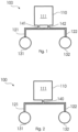
- Figure 1 shows a schematic drawing of an arrangement for supplying two air springs 131, 132 of a secondary suspension of a rail vehicle.
- the secondary suspension is arranged between the car body and the bogie of a rail vehicle.
- the air springs 131, 132 are connected to an additional air volume 111 in a compressed air tank 110.
- the first air spring 131 is connected to the compressed air tank 110 via a first connecting line 121
- the second air spring 132 is connected to the same compressed air tank 110 via a second connecting line 122.
- the compressed air tank 110 has a single compressed air volume 111 to which the two air springs are connected.
- the compressed air tank meets the safety requirements for pressures from 0 bar (MPa) to approximately 10 bar (1.0 MPa). and is equipped accordingly, for example by a suitable wall thickness, the choice of a suitable material, a suitable fastening of the individual parts of the container and the like.
- a single compressed air volume of the compressed air reservoir refers to a volume (e.g., an additional air volume) for connection to an air spring. Subdivisions within the reservoir, which serve, for example, for filling, pressure equalization, stabilization of the reservoir, or similar purposes, are not to be understood as “compressed air volume” within the scope of this application.
- the air spring assembly 100 has a connection 141 to the compressed air tank 110 to establish the connection between the compressed air tank 110 and the connecting line 121.
- the second connecting line 122 is connected to the compressed air tank via connection 142.
- Figure 1 shows that both connecting lines are connected to one side of the compressed air tank 110. This is particularly advantageous in terms of installation space, since the connecting lines can be designed to be relatively short.
- the connecting lines 121 and 122 are also in fluid communication with each other, ie in a connection that allows the exchange of fluids between the two connecting lines.
- the connecting lines 121, 122 are connected to each other and to the compressed air tank by a type of double T-piece, with the double T-piece containing an orifice plate.
- the connection between the connecting lines, as well as the connecting lines themselves, can contain orifices or a control valve for regulating the air flow in the connecting lines.
- FIG 2 shows a further embodiment of the air spring arrangement 100 according to the invention.
- two air springs 131, 132 are connected to two connecting lines 121, 122.
- the connecting lines 121, 122 are in turn connected to a compressed air tank 110 in order to supply compressed air to the air springs 131, 132.
- the two connecting lines 121, 122 have a common connection 140 to the compressed air tank. This can be achieved, for example, by a simple T-piece between the connecting lines 121, 122.
- the common connection 140 increases flexibility, since the required installation space for the compressed air tank does not depend on whether two connections can be accommodated. It also simplifies assembly and maintenance work, since connecting or replacing either the connecting lines or the compressed air tank can be done in a single connection step.
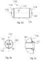
- Figure 3a shows a side view of a compressed air tank 110 for an air spring arrangement 100, as shown for example in the Figures 1 and 2 was shown.
- the compressed air tank 110 is designed as a substantially cylindrical body.
- the compressed air tank is composed of a first dished end 113, a central portion 116, and a second dished end 114.
- the dished ends 113 and 114 close the cylindrical body and can, for example, be welded to the central portion 116.
- the dished ends 113, 114 can be attached to the central portion by means of rivets or similar fastening means.
- the central part 116 of the compressed air tank 110 can be configured as a cylinder.
- the dished ends 113 and 114 can have a first section continuing the cylindrical shape of the central part 116 and an outwardly curved or arched second section.
- the compressed air tank, created by combining the central part 116 and the dished ends 113 and 114, with a substantially cylindrical shape has a longitudinal axis 115 running in the longitudinal direction of the compressed air tank.
- the longitudinal axis 115 can be an axis of symmetry.
- the compressed air tank has a transverse direction 117 extending in the radial direction of the substantially cylindrical compressed air tank.
- the compressed air tank 110 can also have connections for filling the compressed air tank with compressed air, for example, during maintenance work.
- the air suspension arrangement consisting of air springs and additional air volume can, for example, be supplied externally via one or more supply lines. This supply is controlled by at least one level control valve (usually two per vehicle – hence 2-point control).
- the compressed air tank can have seals that largely prevent the compressed air from escaping.
- the compressed air tank can also have openings for draining water.
- Figure 3b showed a front view of the compressed air tank from Figure 3a .
- the dished end 114 is provided with the two connections 141, 142 for the connecting lines 121, 122, as shown in Figure 1 is shown.
- Figure 3b the substantially circular contour of the pressure vessel 110.
- the pressure vessel 110 has a diameter D.
- the diameter D of the compressed air vessel can be up to approximately 50 cm.
- the compressed air vessel can have a total volume of, for example, approximately 80 to 100 liters, but also a volume of up to approximately 200 liters and more.
- connections are arranged at a distance from one another.
- the distance between connections 141 and 142 from the longitudinal axis 115 of the compressed air tank can be the same or different.
- the fastening element 180 allows the compressed air tank or the entire air spring assembly to be easily replaced, for example, for maintenance purposes. However, it is also easy to replace the compressed air tank with a different model of compressed air tank.
- the compressed air tank with one air volume according to the embodiments described herein can be replaced by a compressed air tank with two or more separate compressed air volumes.
- the compressed air tank can be easily dismantled for upgrading or modification to a different model and remounted on the car body or bogie after the upgrade.
- An upgrade not belonging to the invention can be carried out, for example, by inserting a partition wall that transforms the one compressed air volume in the compressed air tank into two separate compressed air volumes in the compressed air tank.
- the compressed air tank can already have a receptacle for a partition wall, for example through corresponding guides, receptacles and/or fastening means.
Landscapes
- Engineering & Computer Science (AREA)
- Mechanical Engineering (AREA)
- Vehicle Body Suspensions (AREA)
- Fluid-Damping Devices (AREA)
Claims (15)
- Système formant ressort pneumatique (100) pour une suspension pneumatique secondaire entre la caisse de voiture et le bogie d'un véhicule ferroviaire, présentant :un premier conduit de raccordement (121) permettant de raccorder un premier ressort pneumatique (131) à un volume d'air comprimé et un deuxième conduit de raccordement (122) permettant de raccorder un deuxième ressort pneumatique (132) à un volume d'air comprimé ; etun réservoir d'air comprimé (110) ;caractérisé en ce que le réservoir d'air comprimé (110) met à disposition un volume d'air comprimé (111) commun ou unique et est conçu pour augmenter un volume d'air compressible du premier et du deuxième ressort pneumatique (131, 132), dans lequel le premier conduit de raccordement (121) ainsi que le deuxième conduit de raccordement (121) sont raccordés au volume d'air comprimé (111), etle réservoir d'air comprimé (110) peut être fixé, en particulier peut être fixé de manière à pouvoir être remplacé, à la caisse de voiture ou au bogie d'un véhicule ferroviaire.
- Système formant ressort pneumatique selon la revendication 1, dans lequel le premier conduit de raccordement (121) et le deuxième conduit de raccordement (122) sont en communication fluidique séparée l'un avec l'autre.
- Système formant ressort pneumatique selon la revendication 2, dans lequel le premier conduit de raccordement (121) et le deuxième conduit de raccordement (122) sont en communication fluidique séparée par l'intermédiaire d'un diaphragme ou d'une soupape de régulation (150) permettant de réguler le flux d'air entre le premier conduit de raccordement et le deuxième conduit de raccordement.
- Système formant ressort pneumatique selon l'une des revendications précédentes, dans lequel le réservoir d'air comprimé (110) présente un premier raccord (141) pour le raccordement du premier conduit de raccordement (121) au volume d'air comprimé (111) et un deuxième raccord (142) pour le raccordement du deuxième conduit de raccordement (122) au volume d'air comprimé (111), dans lequel les deux raccords (141 ; 142) sont disposés sur le même côté du réservoir d'air comprimé (110).
- Système formant ressort pneumatique selon la revendication 4, dans lequel le réservoir d'air comprimé (110) présente deux fonds bombés (113, 114) et dans lequel le premier raccord (141) et le deuxième raccord (142) sont raccordés au réservoir d'air comprimé (110) sur le même fond bombé (114).
- Système formant ressort pneumatique selon l'une des revendications précédentes, dans lequel le réservoir d'air comprimé présente une forme cylindrique circulaire comportant un diamètre extérieur D et au moins l'une des deux extrémités frontales du réservoir d'air comprimé est formée par un fond bombé, dans lequel un premier raccord (141) pour le raccordement du premier conduit de raccordement (121) et un deuxième raccord (142) pour le raccordement du deuxième conduit de raccordement (122) au fond bombé sont disposés dans une zone ayant un rayon de 0,4 x D autour d'un axe longitudinal (115) du réservoir d'air comprimé (110), dans lequel le premier et le deuxième raccord (141 ; 142) peuvent être à une distance identique ou différente de l'axe longitudinal.
- Système formant ressort pneumatique selon l'une des revendications précédentes, dans lequel une régulation en deux points des ressorts pneumatiques (131, 132) est réalisée avec le système formant ressort pneumatique (100).
- Système formant ressort pneumatique selon l'une des revendications précédentes, présentant en outre un ou plusieurs autres conduits de raccordement, dans lequel le ou les autres conduits de raccordement sont raccordés au volume d'air comprimé (111) du réservoir d'air comprimé (110).
- Système formant ressort pneumatique selon l'une des revendications précédentes, dans lequel le réservoir d'air comprimé (110) présente un élément de fixation (180) pour fixer le réservoir d'air comprimé à un véhicule ferroviaire, en particulier à une caisse de voiture ou à un bogie d'un véhicule ferroviaire.
- Système formant ressort pneumatique selon l'une des revendications précédentes, dans lequel le réservoir d'air comprimé (110) présente un logement à l'intérieur du réservoir d'air comprimé, lequel logement peut recevoir une paroi de séparation à l'intérieur du réservoir d'air comprimé permettant de séparer deux volumes.
- Système formant ressort pneumatique selon l'une des revendications précédentes, dans lequel le premier conduit de raccordement (121) et le deuxième conduit de raccordement (122) présentent un raccord commun (140) au volume d'air comprimé (111) commun du réservoir d'air comprimé (110).
- Véhicule ferroviaire comportant une suspension secondaire entre le bogie et la caisse de voiture du véhicule ferroviaire, laquelle suspension secondaire présente pour chaque bogie un premier ressort pneumatique (131) et un deuxième ressort pneumatique (132), dans lequel le véhicule ferroviaire présente un logement pour ainsi qu'un système formant ressort pneumatique (100) selon l'une des revendications précédentes.
- Véhicule ferroviaire selon la revendication 12, dans lequel le logement permet une fixation du réservoir d'air comprimé (110) du système formant ressort pneumatique (100) à la caisse de voiture ou au bogie du véhicule ferroviaire.
- Procédé permettant d'alimenter des ressorts pneumatiques (131 ; 132) d'une suspension secondaire entre caisse de voiture et bogie d'un véhicule ferroviaire, présentant :la fourniture d'un premier raccordement d'air comprimé (121) entre un volume d'air comprimé (111) d'un réservoir d'air comprimé (110) et un premier ressort pneumatique (131) d'une suspension secondaire ;la fourniture d'un deuxième raccordement d'air comprimé (122) entre le même volume d'air comprimé (111) du même réservoir d'air comprimé (110) et un deuxième ressort pneumatique (131) de la suspension secondaire ; etle raccordement du premier raccordement d'air comprimé (121) et du deuxième raccordement d'air comprimé (122) au réservoir d'air comprimé (110) mettant ainsi à disposition un volume d'air comprimé commun ou unique, lequel réservoir d'air comprimé est conçu pour augmenter un volume d'air compressible du premier et du deuxième ressort pneumatique (131, 132).
- Procédé selon la revendication 14, dans lequel la fourniture du premier conduit de raccordement (121) et du deuxième conduit de raccordement (122) présente le raccordement du premier conduit de raccordement (121) et du deuxième conduit de raccordement (122) au réservoir d'air comprimé (110) sur le même côté du réservoir d'air comprimé (110).
Applications Claiming Priority (1)
| Application Number | Priority Date | Filing Date | Title |
|---|---|---|---|
| DE102015112015.1A DE102015112015B3 (de) | 2015-07-23 | 2015-07-23 | Luftfederanordnung für schienenfahrzeug und schienenfahrzeug mit luftfederanordnung |
Publications (3)
| Publication Number | Publication Date |
|---|---|
| EP3121090A1 EP3121090A1 (fr) | 2017-01-25 |
| EP3121090B1 EP3121090B1 (fr) | 2019-09-04 |
| EP3121090B2 true EP3121090B2 (fr) | 2025-07-02 |
Family
ID=56507469
Family Applications (1)
| Application Number | Title | Priority Date | Filing Date |
|---|---|---|---|
| EP16180567.6A Active EP3121090B2 (fr) | 2015-07-23 | 2016-07-21 | Systeme d'amortisseur pneumatique pour vehicule sur rails et vehicule sur rails comprenant un systeme d'amortisseur pneumatique |
Country Status (2)
| Country | Link |
|---|---|
| EP (1) | EP3121090B2 (fr) |
| DE (1) | DE102015112015B3 (fr) |
Cited By (1)
| Publication number | Priority date | Publication date | Assignee | Title |
|---|---|---|---|---|
| US20230264722A1 (en) * | 2020-07-14 | 2023-08-24 | Faiveley Transport Italia S.P.A. | System for recovery of compressed air released by air suspensions of at least one railway vehicle or train |
Families Citing this family (1)
| Publication number | Priority date | Publication date | Assignee | Title |
|---|---|---|---|---|
| DE102018128858A1 (de) * | 2018-11-16 | 2020-05-20 | Bombardier Transportation Gmbh | Luftfederanordnung für eine Sekundärfederung eines Niederflurschienenfahrzeugs, Wagenkasten und Schienenfahrzeug mit Luftfederanordnung |
Family Cites Families (15)
| Publication number | Priority date | Publication date | Assignee | Title |
|---|---|---|---|---|
| US2790650A (en) | 1955-02-22 | 1957-04-30 | Gomma Antivibranti Applic | Pneumatic load-responsive spring suspension for vehicles |
| DE1036072B (de) * | 1955-09-12 | 1958-08-07 | Daimler Benz Ag | Pneumatische Ausgleichsfederung fuer Fahrzeuge |
| DE1214098B (de) * | 1961-07-19 | 1966-04-07 | Italiana Magneti Marelli Soc P | Ausgleichvorrichtung fuer die hoehengleiche Achsenlage zwischen Motorwagen und Anhaenger von Kraftfahrzeugen mit pneumatischer Aufhaengung |
| DE2830359A1 (de) | 1978-07-11 | 1980-01-24 | Knorr Bremse Gmbh | Luftfederung mit niveauregelung fuer fahrzeuge, insbesondere schienenfahrzeuge |
| EP0099597B1 (fr) | 1982-07-23 | 1985-12-11 | Werkzeugmaschinenfabrik Oerlikon-Bührle AG | Système de contrôle pneumatique |
| DE3228603A1 (de) * | 1982-07-30 | 1984-02-02 | Knorr-Bremse GmbH, 8000 München | Federung fuer fahrzeugraeder |
| DE59302145D1 (de) * | 1992-04-30 | 1996-05-15 | Aeg Schienenfahrzeuge | Schienenfahrzeug mit Drehgestellen |
| JPH0617867A (ja) * | 1992-06-29 | 1994-01-25 | Bridgestone Corp | 高さ調整機構付き空気ばね |
| AT407138B (de) * | 1994-09-21 | 2000-12-27 | Siemens Sgp Verkehrstech Gmbh | Laufwerk mit druckbehälter |
| DE10316497A1 (de) * | 2003-04-09 | 2005-01-05 | Bombardier Transportation Gmbh | Fahrwerk für ein Schienenfahrzeug mit verbesserter Querfederung |
| DE102009007674A1 (de) | 2009-02-05 | 2010-08-19 | Knorr-Bremse Systeme für Nutzfahrzeuge GmbH | Niveauregelventil mit je einem Anschluss für Luftfederbälge der rechten und der linken Seite |
| JP4461189B1 (ja) | 2009-02-20 | 2010-05-12 | 三菱重工業株式会社 | 軌道系車両 |
| DE102009036722A1 (de) * | 2009-08-08 | 2010-03-25 | Daimler Ag | Druckluftbehälter |
| WO2012132240A1 (fr) | 2011-03-31 | 2012-10-04 | 住友金属工業株式会社 | Procédé permettant de contrôler l'inclinaison du corps d'un wagon |
| DE102013004906A1 (de) * | 2013-03-15 | 2014-09-18 | Bombardier Transportation Gmbh | Baugruppe für einen Behälter und Schienenfahrzeug mit einer Baugruppe für einen Behälter |
-
2015
- 2015-07-23 DE DE102015112015.1A patent/DE102015112015B3/de active Active
-
2016
- 2016-07-21 EP EP16180567.6A patent/EP3121090B2/fr active Active
Cited By (2)
| Publication number | Priority date | Publication date | Assignee | Title |
|---|---|---|---|---|
| US20230264722A1 (en) * | 2020-07-14 | 2023-08-24 | Faiveley Transport Italia S.P.A. | System for recovery of compressed air released by air suspensions of at least one railway vehicle or train |
| US12589780B2 (en) * | 2020-07-14 | 2026-03-31 | Faiveley Transport Italia S.P.A. | System for recovery of compressed air released by air suspensions of at least one railway vehicle or train |
Also Published As
| Publication number | Publication date |
|---|---|
| EP3121090A1 (fr) | 2017-01-25 |
| EP3121090B1 (fr) | 2019-09-04 |
| DE102015112015B3 (de) | 2016-09-29 |
Similar Documents
| Publication | Publication Date | Title |
|---|---|---|
| DE3233160A1 (de) | Vorrichtung zum federn und stabilisieren von fahrzeugen, insbesondere von kraftfahrzeugen | |
| CH442413A (de) | Einrichtung an Schienenfahrzeugen zur Abstützung des Fahrzeugoberteils auf den Radgestellen | |
| EP2990240A1 (fr) | Kit de montage d'un ressort sur la suspension de roue unique d'un vehicule automobile | |
| EP3558785A1 (fr) | Ensemble d'attelage, en particulier pour un véhicule ferroviaire | |
| EP3121090B2 (fr) | Systeme d'amortisseur pneumatique pour vehicule sur rails et vehicule sur rails comprenant un systeme d'amortisseur pneumatique | |
| WO2016001268A1 (fr) | Support comportant un récipient de compensation d'air | |
| EP3332995B1 (fr) | Flèche d'attelage pour une remorque de véhicule | |
| EP0040675A2 (fr) | Dispositif autopompant de réglage de niveau pour véhicules, en particulier pour véhicules à moteur | |
| EP3121089B1 (fr) | Systeme d'amortisseur pneumatique pour vehicule sur rails et vehicule sur rails comprenant un systeme d'amortisseur pneumatique | |
| DE202018002498U1 (de) | Druckhaltevorrichtung | |
| DE4205367C2 (de) | Achsaufhängung für Kraftfahrzeuge mit Niveauausgleich | |
| DE602006000991T2 (de) | Hinterradaufhängung eines Kraftfahrzeugs | |
| DE102019008257B4 (de) | Modulare Halterungsvorrichtung zum Montieren eines Gegenstands an einem Fahrzeug, Halteranordnung und Fahrzeug umfassend solch eine Halteranordnung | |
| DE102021213990A1 (de) | Kabinenlagerung für ein Nutzfahrzeug sowie Nutzfahrzeug | |
| DE2825149C2 (de) | Wechselaufbau-System für einen zweiachsigen Lastkraftwagen | |
| EP3515732B1 (fr) | Système de ressort pneumatique, véhicule équipé d'un système de ressort pneumatique et procédé de montage d'un système de ressort pneumatique | |
| DE102021113350A1 (de) | Kraftfahrzeug mit einem Federbein | |
| DE1000695B (de) | Vorrichtung an Sattelanhaengern zur Herabsetzung der Kippgefahr beim Laden | |
| DE19524106A1 (de) | Einzelradaufhängung für ein Kfz-Rad | |
| DE924309C (de) | Fluessigkeitsstossdaempfer | |
| DE2200356A1 (de) | Anordnung fuer die luftfederung von fahrzeugen | |
| DE102016015776B4 (de) | Luftfedersystem, Fahrzeug mit Luftfedersystem und Verfahren zur Montage eines Luftfedersystems | |
| DE102023107626A1 (de) | Bremskraftregeleinrichtung mit einem Federhebel für einen Fahrzeuganhänger | |
| DE102022103274A1 (de) | Federbeindom zur Aufnahme eines Federbeins einer Luftfeder sowie Federbein und Fahrzeug | |
| DE102021213991A1 (de) | Kabinenlagerung für ein Nutzfahrzeug sowie Nutzfahrzeug |
Legal Events
| Date | Code | Title | Description |
|---|---|---|---|
| PUAI | Public reference made under article 153(3) epc to a published international application that has entered the european phase |
Free format text: ORIGINAL CODE: 0009012 |
|
| STAA | Information on the status of an ep patent application or granted ep patent |
Free format text: STATUS: THE APPLICATION HAS BEEN PUBLISHED |
|
| AK | Designated contracting states |
Kind code of ref document: A1 Designated state(s): AL AT BE BG CH CY CZ DE DK EE ES FI FR GB GR HR HU IE IS IT LI LT LU LV MC MK MT NL NO PL PT RO RS SE SI SK SM TR |
|
| AX | Request for extension of the european patent |
Extension state: BA ME |
|
| STAA | Information on the status of an ep patent application or granted ep patent |
Free format text: STATUS: REQUEST FOR EXAMINATION WAS MADE |
|
| RAP1 | Party data changed (applicant data changed or rights of an application transferred) |
Owner name: BOMBARDIER TRANSPORTATION GMBH |
|
| 17P | Request for examination filed |
Effective date: 20170719 |
|
| RBV | Designated contracting states (corrected) |
Designated state(s): AL AT BE BG CH CY CZ DE DK EE ES FI FR GB GR HR HU IE IS IT LI LT LU LV MC MK MT NL NO PL PT RO RS SE SI SK SM TR |
|
| GRAP | Despatch of communication of intention to grant a patent |
Free format text: ORIGINAL CODE: EPIDOSNIGR1 |
|
| STAA | Information on the status of an ep patent application or granted ep patent |
Free format text: STATUS: GRANT OF PATENT IS INTENDED |
|
| INTG | Intention to grant announced |
Effective date: 20181023 |
|
| GRAJ | Information related to disapproval of communication of intention to grant by the applicant or resumption of examination proceedings by the epo deleted |
Free format text: ORIGINAL CODE: EPIDOSDIGR1 |
|
| STAA | Information on the status of an ep patent application or granted ep patent |
Free format text: STATUS: REQUEST FOR EXAMINATION WAS MADE |
|
| GRAP | Despatch of communication of intention to grant a patent |
Free format text: ORIGINAL CODE: EPIDOSNIGR1 |
|
| INTC | Intention to grant announced (deleted) | ||
| STAA | Information on the status of an ep patent application or granted ep patent |
Free format text: STATUS: GRANT OF PATENT IS INTENDED |
|
| INTG | Intention to grant announced |
Effective date: 20190321 |
|
| GRAS | Grant fee paid |
Free format text: ORIGINAL CODE: EPIDOSNIGR3 |
|
| GRAA | (expected) grant |
Free format text: ORIGINAL CODE: 0009210 |
|
| STAA | Information on the status of an ep patent application or granted ep patent |
Free format text: STATUS: THE PATENT HAS BEEN GRANTED |
|
| AK | Designated contracting states |
Kind code of ref document: B1 Designated state(s): AL AT BE BG CH CY CZ DE DK EE ES FI FR GB GR HR HU IE IS IT LI LT LU LV MC MK MT NL NO PL PT RO RS SE SI SK SM TR |
|
| REG | Reference to a national code |
Ref country code: GB Ref legal event code: FG4D Free format text: NOT ENGLISH |
|
| REG | Reference to a national code |
Ref country code: CH Ref legal event code: EP |
|
| REG | Reference to a national code |
Ref country code: AT Ref legal event code: REF Ref document number: 1174945 Country of ref document: AT Kind code of ref document: T Effective date: 20190915 |
|
| REG | Reference to a national code |
Ref country code: DE Ref legal event code: R096 Ref document number: 502016006388 Country of ref document: DE |
|
| REG | Reference to a national code |
Ref country code: IE Ref legal event code: FG4D Free format text: LANGUAGE OF EP DOCUMENT: GERMAN |
|
| REG | Reference to a national code |
Ref country code: CH Ref legal event code: NV Representative=s name: TR-IP CONSULTING LLC, CH |
|
| REG | Reference to a national code |
Ref country code: NL Ref legal event code: MP Effective date: 20190904 |
|
| REG | Reference to a national code |
Ref country code: LT Ref legal event code: MG4D |
|
| PG25 | Lapsed in a contracting state [announced via postgrant information from national office to epo] |
Ref country code: SE Free format text: LAPSE BECAUSE OF FAILURE TO SUBMIT A TRANSLATION OF THE DESCRIPTION OR TO PAY THE FEE WITHIN THE PRESCRIBED TIME-LIMIT Effective date: 20190904 Ref country code: HR Free format text: LAPSE BECAUSE OF FAILURE TO SUBMIT A TRANSLATION OF THE DESCRIPTION OR TO PAY THE FEE WITHIN THE PRESCRIBED TIME-LIMIT Effective date: 20190904 Ref country code: FI Free format text: LAPSE BECAUSE OF FAILURE TO SUBMIT A TRANSLATION OF THE DESCRIPTION OR TO PAY THE FEE WITHIN THE PRESCRIBED TIME-LIMIT Effective date: 20190904 Ref country code: LT Free format text: LAPSE BECAUSE OF FAILURE TO SUBMIT A TRANSLATION OF THE DESCRIPTION OR TO PAY THE FEE WITHIN THE PRESCRIBED TIME-LIMIT Effective date: 20190904 Ref country code: BG Free format text: LAPSE BECAUSE OF FAILURE TO SUBMIT A TRANSLATION OF THE DESCRIPTION OR TO PAY THE FEE WITHIN THE PRESCRIBED TIME-LIMIT Effective date: 20191204 Ref country code: NO Free format text: LAPSE BECAUSE OF FAILURE TO SUBMIT A TRANSLATION OF THE DESCRIPTION OR TO PAY THE FEE WITHIN THE PRESCRIBED TIME-LIMIT Effective date: 20191204 |
|
| REG | Reference to a national code |
Ref country code: CH Ref legal event code: PCAR Free format text: NEW ADDRESS: ROUTE DU COUTSET 18, 1485 NUVILLY (CH) |
|
| PG25 | Lapsed in a contracting state [announced via postgrant information from national office to epo] |
Ref country code: AL Free format text: LAPSE BECAUSE OF FAILURE TO SUBMIT A TRANSLATION OF THE DESCRIPTION OR TO PAY THE FEE WITHIN THE PRESCRIBED TIME-LIMIT Effective date: 20190904 Ref country code: ES Free format text: LAPSE BECAUSE OF FAILURE TO SUBMIT A TRANSLATION OF THE DESCRIPTION OR TO PAY THE FEE WITHIN THE PRESCRIBED TIME-LIMIT Effective date: 20190904 Ref country code: LV Free format text: LAPSE BECAUSE OF FAILURE TO SUBMIT A TRANSLATION OF THE DESCRIPTION OR TO PAY THE FEE WITHIN THE PRESCRIBED TIME-LIMIT Effective date: 20190904 Ref country code: RS Free format text: LAPSE BECAUSE OF FAILURE TO SUBMIT A TRANSLATION OF THE DESCRIPTION OR TO PAY THE FEE WITHIN THE PRESCRIBED TIME-LIMIT Effective date: 20190904 Ref country code: GR Free format text: LAPSE BECAUSE OF FAILURE TO SUBMIT A TRANSLATION OF THE DESCRIPTION OR TO PAY THE FEE WITHIN THE PRESCRIBED TIME-LIMIT Effective date: 20191205 |
|
| PG25 | Lapsed in a contracting state [announced via postgrant information from national office to epo] |
Ref country code: IT Free format text: LAPSE BECAUSE OF FAILURE TO SUBMIT A TRANSLATION OF THE DESCRIPTION OR TO PAY THE FEE WITHIN THE PRESCRIBED TIME-LIMIT Effective date: 20190904 Ref country code: PT Free format text: LAPSE BECAUSE OF FAILURE TO SUBMIT A TRANSLATION OF THE DESCRIPTION OR TO PAY THE FEE WITHIN THE PRESCRIBED TIME-LIMIT Effective date: 20200106 Ref country code: RO Free format text: LAPSE BECAUSE OF FAILURE TO SUBMIT A TRANSLATION OF THE DESCRIPTION OR TO PAY THE FEE WITHIN THE PRESCRIBED TIME-LIMIT Effective date: 20190904 Ref country code: NL Free format text: LAPSE BECAUSE OF FAILURE TO SUBMIT A TRANSLATION OF THE DESCRIPTION OR TO PAY THE FEE WITHIN THE PRESCRIBED TIME-LIMIT Effective date: 20190904 Ref country code: EE Free format text: LAPSE BECAUSE OF FAILURE TO SUBMIT A TRANSLATION OF THE DESCRIPTION OR TO PAY THE FEE WITHIN THE PRESCRIBED TIME-LIMIT Effective date: 20190904 Ref country code: PL Free format text: LAPSE BECAUSE OF FAILURE TO SUBMIT A TRANSLATION OF THE DESCRIPTION OR TO PAY THE FEE WITHIN THE PRESCRIBED TIME-LIMIT Effective date: 20190904 |
|
| REG | Reference to a national code |
Ref country code: DE Ref legal event code: R026 Ref document number: 502016006388 Country of ref document: DE |
|
| PG25 | Lapsed in a contracting state [announced via postgrant information from national office to epo] |
Ref country code: IS Free format text: LAPSE BECAUSE OF FAILURE TO SUBMIT A TRANSLATION OF THE DESCRIPTION OR TO PAY THE FEE WITHIN THE PRESCRIBED TIME-LIMIT Effective date: 20200224 Ref country code: SM Free format text: LAPSE BECAUSE OF FAILURE TO SUBMIT A TRANSLATION OF THE DESCRIPTION OR TO PAY THE FEE WITHIN THE PRESCRIBED TIME-LIMIT Effective date: 20190904 Ref country code: SK Free format text: LAPSE BECAUSE OF FAILURE TO SUBMIT A TRANSLATION OF THE DESCRIPTION OR TO PAY THE FEE WITHIN THE PRESCRIBED TIME-LIMIT Effective date: 20190904 Ref country code: CZ Free format text: LAPSE BECAUSE OF FAILURE TO SUBMIT A TRANSLATION OF THE DESCRIPTION OR TO PAY THE FEE WITHIN THE PRESCRIBED TIME-LIMIT Effective date: 20190904 |
|
| PLBI | Opposition filed |
Free format text: ORIGINAL CODE: 0009260 |
|
| PLAX | Notice of opposition and request to file observation + time limit sent |
Free format text: ORIGINAL CODE: EPIDOSNOBS2 |
|
| 26 | Opposition filed |
Opponent name: SIEMENS MOBILITY GMBH Effective date: 20200526 |
|
| PG2D | Information on lapse in contracting state deleted |
Ref country code: IS |
|
| PG25 | Lapsed in a contracting state [announced via postgrant information from national office to epo] |
Ref country code: DK Free format text: LAPSE BECAUSE OF FAILURE TO SUBMIT A TRANSLATION OF THE DESCRIPTION OR TO PAY THE FEE WITHIN THE PRESCRIBED TIME-LIMIT Effective date: 20190904 Ref country code: IS Free format text: LAPSE BECAUSE OF FAILURE TO SUBMIT A TRANSLATION OF THE DESCRIPTION OR TO PAY THE FEE WITHIN THE PRESCRIBED TIME-LIMIT Effective date: 20200105 |
|
| PG25 | Lapsed in a contracting state [announced via postgrant information from national office to epo] |
Ref country code: SI Free format text: LAPSE BECAUSE OF FAILURE TO SUBMIT A TRANSLATION OF THE DESCRIPTION OR TO PAY THE FEE WITHIN THE PRESCRIBED TIME-LIMIT Effective date: 20190904 |
|
| PLBB | Reply of patent proprietor to notice(s) of opposition received |
Free format text: ORIGINAL CODE: EPIDOSNOBS3 |
|
| PG25 | Lapsed in a contracting state [announced via postgrant information from national office to epo] |
Ref country code: MC Free format text: LAPSE BECAUSE OF FAILURE TO SUBMIT A TRANSLATION OF THE DESCRIPTION OR TO PAY THE FEE WITHIN THE PRESCRIBED TIME-LIMIT Effective date: 20190904 |
|
| GBPC | Gb: european patent ceased through non-payment of renewal fee |
Effective date: 20200721 |
|
| REG | Reference to a national code |
Ref country code: BE Ref legal event code: MM Effective date: 20200731 |
|
| PG25 | Lapsed in a contracting state [announced via postgrant information from national office to epo] |
Ref country code: GB Free format text: LAPSE BECAUSE OF NON-PAYMENT OF DUE FEES Effective date: 20200721 Ref country code: LU Free format text: LAPSE BECAUSE OF NON-PAYMENT OF DUE FEES Effective date: 20200721 |
|
| PG25 | Lapsed in a contracting state [announced via postgrant information from national office to epo] |
Ref country code: BE Free format text: LAPSE BECAUSE OF NON-PAYMENT OF DUE FEES Effective date: 20200731 |
|
| PG25 | Lapsed in a contracting state [announced via postgrant information from national office to epo] |
Ref country code: IE Free format text: LAPSE BECAUSE OF NON-PAYMENT OF DUE FEES Effective date: 20200721 |
|
| APBM | Appeal reference recorded |
Free format text: ORIGINAL CODE: EPIDOSNREFNO |
|
| APBP | Date of receipt of notice of appeal recorded |
Free format text: ORIGINAL CODE: EPIDOSNNOA2O |
|
| APAH | Appeal reference modified |
Free format text: ORIGINAL CODE: EPIDOSCREFNO |
|
| PG25 | Lapsed in a contracting state [announced via postgrant information from national office to epo] |
Ref country code: TR Free format text: LAPSE BECAUSE OF FAILURE TO SUBMIT A TRANSLATION OF THE DESCRIPTION OR TO PAY THE FEE WITHIN THE PRESCRIBED TIME-LIMIT Effective date: 20190904 Ref country code: MT Free format text: LAPSE BECAUSE OF FAILURE TO SUBMIT A TRANSLATION OF THE DESCRIPTION OR TO PAY THE FEE WITHIN THE PRESCRIBED TIME-LIMIT Effective date: 20190904 Ref country code: CY Free format text: LAPSE BECAUSE OF FAILURE TO SUBMIT A TRANSLATION OF THE DESCRIPTION OR TO PAY THE FEE WITHIN THE PRESCRIBED TIME-LIMIT Effective date: 20190904 |
|
| APBM | Appeal reference recorded |
Free format text: ORIGINAL CODE: EPIDOSNREFNO |
|
| APBP | Date of receipt of notice of appeal recorded |
Free format text: ORIGINAL CODE: EPIDOSNNOA2O |
|
| PG25 | Lapsed in a contracting state [announced via postgrant information from national office to epo] |
Ref country code: MK Free format text: LAPSE BECAUSE OF FAILURE TO SUBMIT A TRANSLATION OF THE DESCRIPTION OR TO PAY THE FEE WITHIN THE PRESCRIBED TIME-LIMIT Effective date: 20190904 |
|
| APBQ | Date of receipt of statement of grounds of appeal recorded |
Free format text: ORIGINAL CODE: EPIDOSNNOA3O |
|
| APBQ | Date of receipt of statement of grounds of appeal recorded |
Free format text: ORIGINAL CODE: EPIDOSNNOA3O |
|
| PLAB | Opposition data, opponent's data or that of the opponent's representative modified |
Free format text: ORIGINAL CODE: 0009299OPPO |
|
| R26 | Opposition filed (corrected) |
Opponent name: SIEMENS MOBILITY GMBH Effective date: 20200526 |
|
| RAP2 | Party data changed (patent owner data changed or rights of a patent transferred) |
Owner name: ALSTOM HOLDINGS |
|
| P01 | Opt-out of the competence of the unified patent court (upc) registered |
Effective date: 20230822 |
|
| APBU | Appeal procedure closed |
Free format text: ORIGINAL CODE: EPIDOSNNOA9O |
|
| PUAH | Patent maintained in amended form |
Free format text: ORIGINAL CODE: 0009272 |
|
| STAA | Information on the status of an ep patent application or granted ep patent |
Free format text: STATUS: PATENT MAINTAINED AS AMENDED |
|
| 27A | Patent maintained in amended form |
Effective date: 20250702 |
|
| AK | Designated contracting states |
Kind code of ref document: B2 Designated state(s): AL AT BE BG CH CY CZ DE DK EE ES FI FR GB GR HR HU IE IS IT LI LT LU LV MC MK MT NL NO PL PT RO RS SE SI SK SM TR |
|
| REG | Reference to a national code |
Ref country code: DE Ref legal event code: R102 Ref document number: 502016006388 Country of ref document: DE |
|
| PGFP | Annual fee paid to national office [announced via postgrant information from national office to epo] |
Ref country code: DE Payment date: 20250722 Year of fee payment: 10 |
|
| PGFP | Annual fee paid to national office [announced via postgrant information from national office to epo] |
Ref country code: FR Payment date: 20250725 Year of fee payment: 10 Ref country code: AT Payment date: 20250722 Year of fee payment: 10 |
|
| PGFP | Annual fee paid to national office [announced via postgrant information from national office to epo] |
Ref country code: CH Payment date: 20250801 Year of fee payment: 10 |