EP3121103A1 - Fourche avant - Google Patents
Fourche avant Download PDFInfo
- Publication number
- EP3121103A1 EP3121103A1 EP15765526.7A EP15765526A EP3121103A1 EP 3121103 A1 EP3121103 A1 EP 3121103A1 EP 15765526 A EP15765526 A EP 15765526A EP 3121103 A1 EP3121103 A1 EP 3121103A1
- Authority
- EP
- European Patent Office
- Prior art keywords
- vehicle body
- cap
- members
- front fork
- body side
- Prior art date
- Legal status (The legal status is an assumption and is not a legal conclusion. Google has not performed a legal analysis and makes no representation as to the accuracy of the status listed.)
- Withdrawn
Links
Images


Classifications
-
- B—PERFORMING OPERATIONS; TRANSPORTING
- B62—LAND VEHICLES FOR TRAVELLING OTHERWISE THAN ON RAILS
- B62K—CYCLES; CYCLE FRAMES; CYCLE STEERING DEVICES; RIDER-OPERATED TERMINAL CONTROLS SPECIALLY ADAPTED FOR CYCLES; CYCLE AXLE SUSPENSIONS; CYCLE SIDECARS, FORECARS, OR THE LIKE
- B62K25/00—Axle suspensions
- B62K25/04—Axle suspensions for mounting axles resiliently on cycle frame or fork
- B62K25/06—Axle suspensions for mounting axles resiliently on cycle frame or fork with telescopic fork, e.g. including auxiliary rocking arms
- B62K25/08—Axle suspensions for mounting axles resiliently on cycle frame or fork with telescopic fork, e.g. including auxiliary rocking arms for front wheel
-
- B—PERFORMING OPERATIONS; TRANSPORTING
- B62—LAND VEHICLES FOR TRAVELLING OTHERWISE THAN ON RAILS
- B62K—CYCLES; CYCLE FRAMES; CYCLE STEERING DEVICES; RIDER-OPERATED TERMINAL CONTROLS SPECIALLY ADAPTED FOR CYCLES; CYCLE AXLE SUSPENSIONS; CYCLE SIDECARS, FORECARS, OR THE LIKE
- B62K21/00—Steering devices
- B62K21/02—Front wheel forks or equivalent, e.g. single tine
-
- B—PERFORMING OPERATIONS; TRANSPORTING
- B62—LAND VEHICLES FOR TRAVELLING OTHERWISE THAN ON RAILS
- B62K—CYCLES; CYCLE FRAMES; CYCLE STEERING DEVICES; RIDER-OPERATED TERMINAL CONTROLS SPECIALLY ADAPTED FOR CYCLES; CYCLE AXLE SUSPENSIONS; CYCLE SIDECARS, FORECARS, OR THE LIKE
- B62K21/00—Steering devices
- B62K21/04—Fork crowns
-
- F—MECHANICAL ENGINEERING; LIGHTING; HEATING; WEAPONS; BLASTING
- F16—ENGINEERING ELEMENTS AND UNITS; GENERAL MEASURES FOR PRODUCING AND MAINTAINING EFFECTIVE FUNCTIONING OF MACHINES OR INSTALLATIONS; THERMAL INSULATION IN GENERAL
- F16F—SPRINGS; SHOCK-ABSORBERS; MEANS FOR DAMPING VIBRATION
- F16F9/00—Springs, vibration-dampers, shock-absorbers, or similarly-constructed movement-dampers using a fluid or the equivalent as damping medium
- F16F9/32—Details
- F16F9/3207—Constructional features
Definitions
- the present invention relates to a front fork.
- a front fork is interposed between a vehicle body and a front wheel in a saddle-ride type vehicle such as a two-wheeled vehicle to steer the front wheel.
- a front fork that includes a pair of telescopic tube members having vehicle body side tubes and vehicle wheel side tubes and standing on both sides of the front wheel, an upper bracket on an upper side and an under bracket on a lower side, which couple the vehicle body sides tube of the pair of tube members and couple the vehicle body side tube to a vehicle body frame, which is a frame of a vehicle body, and an axle bracket, which couples the vehicle wheel side tubes of the pair of tube members to a wheel axis of the front wheel.
- the above-described front fork includes springs and dampers inside the tube members to reduce an impact caused by unevenness on a road surface, thus providing a comfortable ride of a vehicle (for example, JP2011-220494A , JP2008-265534A , and JP8-142968A ).
- Cap members are screwed with inner peripherals of upper side opening potions of the vehicle body side tubes in such front fork.
- the cap members cover the upper openings of the tube members.
- the upper bracket includes a pair of clamps.
- the clamps are split and clamped to be secured to outer peripheries of the upper side opening portions of the vehicle body side tubes. This prevents looseness of the cap members.
- the under bracket includes a pair of clamps as well. The clamps are split and clamped to be secured to outer peripheries of centers of the vehicle body side tubes (for example, JP8-270707A ).
- the above-described front fork has a structure where the tube members are inserted from a lower side of the under bracket to the clamps of the under bracket and then are inserted from a lower side of an upper bracket to clamps of the upper bracket.
- An upper joining portion of the vehicle body side tube to which the clamps of the upper bracket are mounted is thinner than a lower joining portion to which the clamps of the under bracket are mounted.
- An outside diameter of the cap member is formed smaller than an outside diameter of the upper joining portion.
- An external thread process is performed on an outer periphery of the cap member.
- a front fork disclosed in JP2013-19505A partitions an air chamber for adjustment outside tube members.
- the air chamber for adjustment is communicated with air chambers, which are formed inside the tube members, to ensure adjustment of an amount of air in the air chambers inside the tube members.
- the above-described front fork forms communication holes that communicate an inside with an outside of the tube members at the tube members.
- An air sealing jig is mounted outside the tube members to communicate the air chambers inside the tube members with the air chamber for adjustment via the communication holes. That is, this avoids the air sealing jig, which is the member for additional functions, to be directly mounted to the cap members under strict dimensional restrictions.
- a front fork disclosed in JP2014-208510A includes control passages, which communicate action chambers of dampers, valve elements, which open and close the control passages, proportional solenoids, which control valve opening pressures of the valve elements, and pressure sensors, which detect pressures of the control passages, outside the tube members. Based on values detected by the pressure sensors, an amount of current to be supplied to the proportional solenoids is changed to adjust the valve opening pressures of the valve elements, thus ensuring adjusting a damping force.
- the above-described front fork forms the control passages in housings disposed outside the tube members.
- the valve elements, the proportional solenoids, and the pressure sensors are mounted to these housings.
- the housings and caps are coupled via hoses. That is, this front fork avoids directly mounting the valve elements, the proportional solenoids, and the pressure sensors, which are the members for additional functions, to the cap members under strict dimensional restrictions.
- An object of the present invention is to provide a front fork where dimensional restrictions when members for additional functions are mounted to members that cover upper side openings of tube members are loosened and eases a direct mounting of the members for additional functions to the members covering the upper side openings of the tube members.
- a front fork including a pair of telescopic tube members that include vehicle body side tubes and vehicle wheel side tubes; and an upper bracket on an upper side and an under bracket on a lower side, the upper bracket and the under bracket coupling the vehicle body side tubes of the pair of tube members and coupling the vehicle body side tubes to a vehicle body side, is provided.
- the upper bracket includes a pair of cap portions into which upper side opening portions of the vehicle body side tubes are inwardly inserted, and the cap portions cover upper side openings of the tube members.
- the front fork F includes a pair of telescopic tube members T and T, which include vehicle body side tubes 1 and vehicle wheel side tubes 2, and an upper bracket B1 on an upper side and an under bracket B2 on a lower side, which couple the vehicle body side tubes 1 of the pair of tube members T and T and couple the vehicle body side tubes 1 to a vehicle body side.
- the upper bracket B1 includes a pair of cap portions 3a and 3a into which upper side opening portions 1a of the vehicle body side tubes 1 are inwardly inserted.
- the cap portions 3a and 3a cover the upper side openings of the tube members T and T.
- the front fork F is interposed between a vehicle body and a front wheel in a saddle-ride type vehicle such as a two-wheeled vehicle and a three-wheeled vehicle.
- the front fork F includes a steering shaft S, which is supported to a head tube P of a vehicle body frame, a frame of a vehicle body, the upper bracket B1 secured to an upper end portion of the steering shaft S, the under bracket B2 secured to a lower end portion of the steering shaft S, a pair of axle brackets B3 and B3 coupled to a wheel axis of a front wheel, and a pair of shock absorbers AL and AR, which are interposed between the upper and lower brackets B1, B2 and the axle brackets B3, B3 and stand on both sides of the front wheel.
- An operation of a handlebar (not illustrated), which is secured to an upper side of the upper bracket B1, rotates the front fork F around an axis of the head tube P, thus changing a direction of the front wheel.
- the shock absorbers AL and AR both include the telescopic tube member T, which becomes an outer shell, and a damper D, which is disposed inside the tube member T.
- a reservoir R between the tube member T and the damper D accumulates liquid and forms a liquid accumulating chamber RI.
- a liquid surface O of the liquid accumulating chamber RI compressed air is sealed, forming an air chamber G.
- the front fork F of this embodiment ensures elastically supporting the vehicle body by a reactive force from the compressed air. That is, the front fork F is an air suspension front fork that eliminates a suspension spring (a main spring), which is formed of a coil spring.
- a suspension spring a main spring
- the configuration of the front fork F is appropriately changeable.
- the suspension spring formed of the coil spring may elastically support the vehicle body.
- Structures of the shock absorbers AL and AR are also appropriately changeable.
- the paired shock absorbers AL and AR both include both the damper D and a spring element, which elastically supports the vehicle body.
- basic configurations of the shock absorbers AL and AR may be completely different.
- the tube member T is the telescopic type and includes the vehicle body side tube 1 and the vehicle wheel side tube 2, which exits and enters the vehicle body side tube 1 while supported by a pair of upper and lower bearings 20 and 10.
- the vehicle body side tube 1 is coupled to the vehicle body side via the upper bracket B1 and the under bracket B2, and the vehicle wheel side tube 2 is coupled to the vehicle wheel side via the axle bracket B3.
- the vehicle wheel side tubes 2 exit and enter the vehicle body side tubes 1, extracting and contracting the shock absorbers AL and AR.
- the upper bracket B1 which is mounted to an outer periphery of the upper side opening portion 1a of the vehicle body side tube 1, covers the upper side opening of the tube member T.
- the axle bracket B3 which is mounted to an outer periphery of the lower side opening portion of the vehicle wheel side tube 2, covers the lower side opening of the tube member T.
- An annular sealing member 11 covers a lower side opening, which is a tubular clearance formed at an overlapping portion where the vehicle body side tube 1 overlaps the vehicle wheel side tube 2.
- the sealing member 11 is held to an inner peripheral of the lower side opening portion of the vehicle body side tube 1 and slidably in contact with the outer peripheral surface of the vehicle wheel side tube 2. This avoids the liquid and gas housed in the tube member T to leak outside the tube member T.
- This embodiment configures the tube member T as an inverted type such that the vehicle wheel side tube 2 exits and enters the vehicle body side tube 1.
- the tube member T may be configured to be an erecting type such that the vehicle body side tube 1 exits and enters the vehicle wheel side tube 2.
- the damper D includes a tubular cylinder 21, an action chamber L formed inside the cylinder 21 and filled with liquid, a piston 12, which slidably moves inside the cylinder 21 axially to partition the action chamber L into an expansion-side chamber L1 and a contraction-side chamber L2, a rod 13 coupled to the piston 12 and one end of which extends outside the cylinder 21, an expansion-side damping passage 14, which provides a resistance to a flow of the liquid heading from the expansion-side chamber L1 to the contraction-side chamber L2, a contraction-side suction passage 15, which allows a flow of the liquid heading from the contraction-side chamber L2 to the expansion-side chamber L1, an expansion-side suction passage 22, which allows a flow of the liquid heading from the reservoir R to the contraction-side chamber L2, and a contraction-side damping passage 23, which provides a resistance to a flow of the liquid heading from the contraction-side chamber L2 to the reservoir R.
- the cylinder 21 is coupled to the axle bracket B3 and stands at a shaft center portion of the vehicle wheel side tube 2.
- One end of the rod 13, which projects from the cylinder 21, is coupled to the upper bracket B 1.
- the dampers D mainly generate an expansion-side damping force depending on a speed caused by the resistances of the expansion-side damping passages 14 to restrain the expansion operation of the shock absorbers AL and AR.
- the reservoirs R compensate a change in an internal volume of the cylinders by the volume of exiting the rods.
- the rods 13 enter the cylinders 21 and the liquid in the contracted contraction-side chambers L2 passes through the pressure-side suction passages 15 and move to the enlarged expansion-side chambers L1. Further, the liquid by the volume of the entrance of the rods passes through the pressure-side damping passages 23 to move from the contraction-side chambers L2 to the reservoirs R. Accordingly, the dampers D mainly generate a pressure-side damping force depending on a speed caused by the resistances of the pressure-side damping passages 23 to restrain the compression operation of the shock absorbers AL and AR.
- the reservoirs R compensate a change in an internal volume of the cylinders by the volume of the entrance of the rods.
- the cylinders 21 are coupled to the vehicle wheel side and the rods 13 are coupled to the vehicle body side, thus configured to be the erecting type.
- a valve element 17 which opens and closes the bypass passage 16a
- a proportional solenoid 18 which controls a valve opening pressure of the valve element 17, and a pressure sensor 19 (see FIG. 3 ), which detects a pressure of the bypass passage 16a, forming a part of the bypass passage 16a at the rod 13 allows the proportional solenoid 18 and the pressure sensor 19 to be easily disposed on the vehicle body side, which is on the spring.
- the valve element 17 which opens and closes the bypass passage 16b
- the proportional solenoid 18 which controls the valve opening pressure of the valve element 17, and the pressure sensor 19 (see FIG. 3 ), which detects a pressure of the bypass passage 16b, forming a part of the bypass passage 16b at the rod 13 allows the proportional solenoid 18 and the pressure sensor 19 to be easily disposed on the vehicle body side, which is on the springs.
- the shock absorbers AL and AR can share many components.
- the shock absorber AR configured to adjust the contraction-side damping force
- the damper D of a stand upside-down type the proportional solenoid 18 and the pressure sensor 19 are easily disposed on the vehicle body side. Accordingly, in this case, even if the shock absorber AL is configured to adjust the expansion-side damping force, only the damper D for the shock absorber AR may be the stand upside-down type.
- a configuration to adjust the dampers D for the shock absorbers AL and AR and the damping force are not limited to the above-described configuration, but can be appropriately changed.
- the dampers D for the shock absorbers AL and AR may include (an) expandable/compressible cylinder-inside air chamber(s) that compensates the change in internal volume of the cylinder(s) inside the cylinder(s) 21.
- the damping force generated by the damper D may be manually adjusted, or a damping force adjustment function may be dispensed.
- the upper bracket B1 couples the upper side opening portions 1a of the vehicle body side tubes 1, which are provided with the respective shock absorbers AL and AR, and couples the vehicle body side tubes 1 to the vehicle body side.
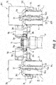
- the upper bracket B1 is trisected and, as illustrated in FIG. 2 , includes a pair of cap members 3L and 3R and one center member 4. Viewing the front fork F from the front, a pair of the cap members 3L and 3R symmetrically have a common configuration laterally.
- the center member 4 has a laterally symmetrical shape.
- the center member 4 is interposed between the cap members 3L and 3R, which are arranged laterally, and is joined to the respective cap members 3L and 3R with bolts 5.
- the center member 4 and the cap members 3L and 3R are each joined with the three bolts 5. It should be noted that, the number of the bolts 5 for joining and locations of the bolts 5 can be appropriately changed.
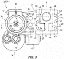
- FIG. 3 and FIG. 4 illustrate only the cap member 3L, the following refers to FIG. 3 and FIG. 4 regarding a description on the cap member 3R as well.
- the cross-sectional surface of the upper bracket B1 illustrated in FIG. 2 is laterally symmetrically taken along the line II in FIG. 3 .
- the cap members 3L and 3R both include the cap-shaped cap portion 3a into which the upper side opening portion 1 a of the vehicle body side tube 1 is inwardly inserted, a fitted portion 3b, which is coupled to the center member 4, and a tank 3c, which internally includes a sub-air chamber g (see FIG. 1 ).
- Bolt insertion holes 3d which fix a handlebar, are formed at boundaries of the cap portions 3a and the fitted portions 3b in the cap members 3L and 3R.
- the fitted portions 3b include bolt insertion holes 3e to fix the center member 4.
- cap members 3L and 3R include control passages 3f opening to the reservoirs R.
- the control passage 3f constitutes the bypass passage 16a or the bypass passage 16b together with shaft center holes 13a, which are formed at the rods 13.
- valve elements 17 which open and close the control passages 3f
- the proportional solenoids 18, which control the valve opening pressures of the valve elements 17, and the pressure sensors 19 which detect a pressure on the damper D side upstream with respect to the valve elements 17 in the control passages 3f, are mounted.
- communication passages 3g (see FIG. 1 and FIG. 3 ), which are open to the reservoirs R to communicate the air chamber G with the sub-air chamber g, are formed.
- the tanks 3c, the proportional solenoids 18, and the pressure sensors 19 are disposed so as not to interfere with the handlebar mounted to the upper bracket B 1.
- the front fork F employs an air suspension system.
- a compression ratio of a chamber that seals compressed air is decided according to desired properties of the spring.
- this embodiment communicates the air chamber G with the sub-air chamber g via the communication passage 3g, thereby ensuring increasing a volume of the chamber that seals the compressed air.
- expanding the chamber that houses the compressed air up to the sub-air chamber g ensures heightening a liquid surface height inside the tube member T. This allows the cylinder 21 to internally suction liquid with less mixture of air bubble, ensuring improving performance of the damper D.
- the tanks 3c, the valve elements 17, the proportional solenoids 18, and the pressure sensors 19 are mounted to the cap members 3L and 3R, which cover the upper side openings of the tube members T.
- the members for additional functions mounted to the cap members 3L and 3R can be appropriately changed according to a type of the additional function added to the front fork F.
- cap portions 3a of the cap members 3L and 3R An internal thread process is performed on inner peripherals of the cap portions 3a of the cap members 3L and 3R, and the cap portions 3a are screwed with outer peripheries of the upper side opening portions 1a of the vehicle body side tubes 1.
- the cap portion 3a has a cutout 30. Screwing a bolt 6 ensures split clamping by narrowing down the cutout 30 to secure, thus stopping looseness of screw joining of the cap portions 3a with the vehicle body side tubes 1.
- the upper side opening portions 1a of the vehicle body side tubes 1 are inserted into the members covering the upper side openings of the tube members T, that is, the insides of the cap portions 3a of the cap members 3L and 3R, which constitute the upper bracket B1.
- the vehicle wheel side tubes 2 are insertable up to thread engagement portions of the vehicle body side tubes 1 with the cap members 3L and 3R. This ensures lengthening a stroke or lengthening a fitting length of the vehicle body side tubes 1 and the vehicle wheel side tubes 2, thereby ensuring providing a distance between the bearings 10 and 20. This stably supports the vehicle wheel side tubes 2, ensuring restraining unsteadiness.
- the upper side opening portion 1a of the vehicle body side tube 1 is inserted into the inside of the cap portion 3a, a method for coupling the cap portion 3a and the vehicle body side tube 1 can be appropriately changed.
- the internal thread process for the cap portion 3a may be omitted and the cap portion 3a may be secured only by being split and clamped. Screwing nuts with the outer peripheries of the upper side opening portions 1a of the vehicle body side tubes 1 in series to the cap members 3L and 3R may stop the looseness.
- the fitted portions 3b which are coupled to the center member 4 at the cap members 3L and 3R, include base portions 31, which have a thick wall wider in a front-rear direction, center portions 32, which extend from the lower portions of the base portions 31 to the center member 4 side and have a thinner wall whose front-rear width is narrower than those of the base portions 31, and distal end portions 33, which extend from the rear portions of the center portions 32 to the center member 4 side and whose upper portions project to an upper side with respect to the center portions 32.
- a surface of the base portion 31 and a surface of the distal end portion 33 opposed in a right-left direction are configured as right-left direction securing surfaces a1 and a2.
- a front surface of the center portion 32 and a rear surface from the center portion 32 to the distal end portion 33, which are opposed back to back in the front-rear direction, are configured as front-rear direction securing surfaces b1 and b2.
- the three bolt insertion holes 3e are aligned back and forth.
- the internal thread process is performed on the inner peripherals of the bolt insertion holes 3e, 3e, and 3e to ensure screwing the bolts 5, which couple the cap members 3L and 3R to the center member 4.
- Stacking and fitting the center member 4 over/to the fitted portions 3b of the cap members 3L and 3R from the upper side brings an end surface 40 of the center member 4 on the cap member 3L and 3R side in contact with the right-left direction securing surfaces a1 of the base portions 31.
- a groove wall 41 which is continuous with the shallow groove 4b at the deep groove 4c, contacts the right-left direction securing surfaces a2 of the distal end portions 33. This restricts the unsteadiness of the center member 4 with the cap members 3L and 3R in the right-left direction.
- Fitting the center member 4 to the cap members 3L and 3R brings a groove wall 42, which is on the front side of the shallow groove 4b of the center member 4, in contact with the front-rear direction securing surfaces b1, which are on the front side of the center portions 32.
- a groove wall 43 which is on the rear side from the shallow groove 4b to the deep groove 4c, contacts the front-rear direction securing surfaces b2 from the center portions 32 to the distal end portions 33. This restricts the unsteadiness of the center member 4 with the cap members 3L and 3R in the front-rear direction.
- three bolt insertion holes 4d are openly bored in the front-rear direction from the upper side to the shallow groove 4b.
- the bolt insertion holes 4d of the center member 4 are opposed to the bolt insertion holes 3e of the cap members 3L and 3R. Accordingly, with a bottom 44 of the shallow groove 4b abutting against the top surfaces of the center portions 32, the bolts 5 are inserted through the bolt insertion holes 4d for screwing with the bolt insertion holes 3e. This restricts the unsteadiness of the center member 4 with the cap members 3L and 3R in the up-down direction.
- the center member 4 and the cap members 3L and 3R are fitted to one another and are joined together with the bolts 5, thus preventing the unsteadiness in the front-rear, right-left, and up-down directions.
- the structure of fitting the center member 4 to the cap members 3L and 3R and the method for coupling the center member 4 to the cap members 3L and 3R are not limited to the above-described structure and method. It is only necessary that the center member 4 is not separated from the cap members 3L and 3R during vehicle running.
- the under bracket B2 which couples the center portions of the vehicle body side tubes 1 in the respective shock absorbers AL and AR and couples the vehicle body side tubes 1 to the vehicle body side, is not configured to be a divided type like the upper bracket B1 in this embodiment.
- a centering portion (not illustrated), which is secured to a lower end portion of the steering shaft S, is integrated with a pair of clamps 7L and 7R (see FIG. 1 ), which are split and clamped to be secured to the outer peripheries of the center portions of the vehicle body side tubes 1.
- the under bracket configured by integrating the centering portion and a pair of the clamps is well-known; therefore, a detailed illustration is omitted.
- the following describes a method for assembling the front fork F according to the embodiment.
- the tube members T Before liquid is poured to the tube members T to which the axle brackets B3 have been mounted, the tube members T are passed through the under bracket B2 to which the steering shaft S has been secured. After the liquid is poured to the tube members T, the cap members 3L and 3R are temporarily fastened to constitute a front fork assembly.
- the steering shaft S of the front fork assembly is inserted into the head tube P.
- the center member 4 is secured to an upper end portion of the steering shaft S projecting from the head tube P.
- the center member 4 is fitted to the cap members 3L and 3R and is secured with the bolts 5.
- the cap members 3L and 3R include the cap portions 3a, which are coupled to the tube members T, and the fitted portions 3b, which are coupled to the center member 4.
- the center member 4 is stacked on the upper sides of the fitted portions 3b.
- this configuration mounts the cap members 3L and 3R to the tube members T, and then mounts the center member 4 to the cap members 3L and 3R, thus ensuring easy coupling with the steering shaft S.
- the configuration of the coupling parts of the center member 4 with the cap members 3L and 3R is not limited to the above-described configuration but can be appropriately changed.
- the upper bracket B1 is divided into three, the center member 4 coupled to the steering shaft S, the one cap member 3L, which includes the one cap portion 3a among a pair of the cap portions 3a and 3a, and the other cap member 3L, which includes the other cap portion 3a.
- the cap members 3L and 3R can cover the upper side openings of the tube members T in the front fork assembly. This ensures preventing a mixture of a foreign matter inside the tube members T, thereby ensuring improvement in convenience during, for example, storing, moving, and transporting the front fork assembly.
- the upper bracket B1 divided into two or more can achieve the effect. It should be noted that, the number of divisions and positions at which the upper bracket B1 is divided can be appropriately changed. As described above, in the case where the upper bracket B1 is divided into the center member 4 and a pair of the cap members 3L and 3R, the upper bracket B1 is easily coupable to the steering shaft S.
- the upper bracket B1 may not be divided.
- the pair of tube members T and T are passed through the under bracket B2 and then are mounted to the vehicle body.
- the paired tube members T and T are individually mountable to the vehicle body.
- this embodiment which employs the integrated under bracket B2, can use the existing under bracket. Accordingly, there is no need to check a strength of the under bracket B2 again. The strength needs to be checked again for the divided under bracket B2.
- the front fork F includes a pair of the telescopic tube members T and T, which include the vehicle body side tubes 1 and the vehicle wheel side tubes 2, and the upper bracket B1 on the upper side and the under bracket B2 on the lower side, which couple the vehicle body side tubes 1 of the pair of tube members T and T and couple the vehicle body side tubes 1 to the vehicle body side.
- the upper bracket B1 includes a pair of the cap portions 3a and 3a into which the upper side opening portions 1a of the vehicle body side tubes 1 are inwardly inserted.
- the cap portions 3a and 3a cover the upper side openings of the tube members T and T.
Landscapes
- Engineering & Computer Science (AREA)
- Mechanical Engineering (AREA)
- General Engineering & Computer Science (AREA)
- Fluid-Damping Devices (AREA)
- Axle Suspensions And Sidecars For Cycles (AREA)
Applications Claiming Priority (2)
| Application Number | Priority Date | Filing Date | Title |
|---|---|---|---|
| JP2014053506A JP6349116B2 (ja) | 2014-03-17 | 2014-03-17 | フロントフォーク |
| PCT/JP2015/056807 WO2015141508A1 (fr) | 2014-03-17 | 2015-03-09 | Fourche avant |
Publications (2)
| Publication Number | Publication Date |
|---|---|
| EP3121103A1 true EP3121103A1 (fr) | 2017-01-25 |
| EP3121103A4 EP3121103A4 (fr) | 2017-11-15 |
Family
ID=54144480
Family Applications (1)
| Application Number | Title | Priority Date | Filing Date |
|---|---|---|---|
| EP15765526.7A Withdrawn EP3121103A4 (fr) | 2014-03-17 | 2015-03-09 | Fourche avant |
Country Status (5)
| Country | Link |
|---|---|
| US (1) | US20170015384A1 (fr) |
| EP (1) | EP3121103A4 (fr) |
| JP (1) | JP6349116B2 (fr) |
| CN (1) | CN106103260A (fr) |
| WO (1) | WO2015141508A1 (fr) |
Cited By (2)
| Publication number | Priority date | Publication date | Assignee | Title |
|---|---|---|---|---|
| US10807670B2 (en) | 2017-04-21 | 2020-10-20 | Sram, Llc | Bicycle suspension component and analysis device |
| US11891146B2 (en) | 2019-12-17 | 2024-02-06 | Sram, Llc | Bicycle suspension components and electronic monitoring devices |
Families Citing this family (2)
| Publication number | Priority date | Publication date | Assignee | Title |
|---|---|---|---|---|
| JP6581511B2 (ja) * | 2016-01-05 | 2019-09-25 | Kyb株式会社 | フロントフォーク |
| US11173982B2 (en) * | 2017-08-04 | 2021-11-16 | Joshua J. Angell | Active air spring |
Family Cites Families (17)
| Publication number | Priority date | Publication date | Assignee | Title |
|---|---|---|---|---|
| CH293599A (de) * | 1948-10-01 | 1953-09-30 | Bayerische Motoren Werke Ag | Gabelkopf für Teleskopgabeln von Krafträdern. |
| DE910751C (de) * | 1952-04-02 | 1954-05-06 | Hemscheidt Maschf Hermann | Teleskopkraftradgabel |
| US2768836A (en) * | 1953-03-18 | 1956-10-30 | Alfred Kreidler | Telescopic forks for motorcycles or the like |
| US5417446A (en) * | 1994-09-08 | 1995-05-23 | Halson Designs, Inc. | Air damping for bicycle shock absorbing fork |
| EP0994014A1 (fr) * | 1998-10-16 | 2000-04-19 | Oskar Diener AG, Feinmechanik | Dispositif antivibratoire hydraulique pour roue avant et/ou arrière d'une véhicule à deux roues |
| US6299190B1 (en) * | 2000-05-05 | 2001-10-09 | Chi-Tai Su | Frame for a motorbike front fork |
| US7111700B2 (en) * | 2003-07-31 | 2006-09-26 | Motoczysz Llc | Coaxial steering and suspension for motorcycle |
| US7207585B2 (en) * | 2003-07-31 | 2007-04-24 | Motoczysz Llc | Front suspension for motorcycle |
| GB0408150D0 (en) * | 2004-04-13 | 2004-05-19 | Ridehough Benjamin J | Variable geometry to alter "rake" and "trial" on motorcycles and the like |
| US7497307B2 (en) * | 2005-02-18 | 2009-03-03 | Costa Vincenzo F | Hidden brake line suspension |
| US20090007714A1 (en) * | 2006-02-06 | 2009-01-08 | Carlini Tony J | Vehicle Steering Assembly |
| US7775176B2 (en) * | 2006-07-05 | 2010-08-17 | Reagan Abel | Device for adjustably suspending a boat fender from a rod holder |
| US7882916B2 (en) * | 2007-05-30 | 2011-02-08 | Yamaha Hatsudoki Kabushiki Kaisha | Vehicle |
| JP5208065B2 (ja) * | 2008-10-02 | 2013-06-12 | カヤバ工業株式会社 | フロントフォーク |
| CN201390353Y (zh) * | 2009-02-21 | 2010-01-27 | 达建工业股份有限公司 | 空间可调行程转换避震缓冲器 |
| US8499906B2 (en) * | 2009-09-15 | 2013-08-06 | Shimano Inc. | Bicycle suspension having stroke and damper adjustment |
| DE102012024776A1 (de) * | 2012-07-20 | 2014-01-23 | Thomas Kamm | Verdrehsteife Fahrwerksführung für Einspurfahrzeuge |
-
2014
- 2014-03-17 JP JP2014053506A patent/JP6349116B2/ja active Active
-
2015
- 2015-03-09 WO PCT/JP2015/056807 patent/WO2015141508A1/fr not_active Ceased
- 2015-03-09 CN CN201580013485.0A patent/CN106103260A/zh active Pending
- 2015-03-09 US US15/124,082 patent/US20170015384A1/en not_active Abandoned
- 2015-03-09 EP EP15765526.7A patent/EP3121103A4/fr not_active Withdrawn
Cited By (4)
| Publication number | Priority date | Publication date | Assignee | Title |
|---|---|---|---|---|
| US10807670B2 (en) | 2017-04-21 | 2020-10-20 | Sram, Llc | Bicycle suspension component and analysis device |
| TWI734910B (zh) * | 2017-04-21 | 2021-08-01 | 美商速聯有限責任公司 | 自行車懸吊組件及分析裝置 |
| US11738821B2 (en) | 2017-04-21 | 2023-08-29 | Sram, Llc | Bicycle suspension component and analysis device |
| US11891146B2 (en) | 2019-12-17 | 2024-02-06 | Sram, Llc | Bicycle suspension components and electronic monitoring devices |
Also Published As
| Publication number | Publication date |
|---|---|
| CN106103260A (zh) | 2016-11-09 |
| JP6349116B2 (ja) | 2018-06-27 |
| JP2015174578A (ja) | 2015-10-05 |
| EP3121103A4 (fr) | 2017-11-15 |
| WO2015141508A1 (fr) | 2015-09-24 |
| US20170015384A1 (en) | 2017-01-19 |
Similar Documents
| Publication | Publication Date | Title |
|---|---|---|
| EP2123933A2 (fr) | Amortisseur et véhicule | |
| JP4341830B2 (ja) | 自動二輪車等のフロントフォーク | |
| EP3121103A1 (fr) | Fourche avant | |
| US9279470B2 (en) | Front fork | |
| US7413064B2 (en) | Front fork | |
| JP6121888B2 (ja) | 懸架装置および懸架システム | |
| JP5831829B2 (ja) | 懸架装置 | |
| US11345431B2 (en) | Pressurized telescopic front fork leg, front fork and vehicle | |
| CN103097760B (zh) | 前叉 | |
| CN105765262B (zh) | 缓冲器 | |
| US9488243B2 (en) | Damper with a vehicle height adjusting function | |
| US6375170B1 (en) | Spring system | |
| WO2016047471A1 (fr) | Fourche avant | |
| JP5909384B2 (ja) | 緩衝器 | |
| JP2020143700A (ja) | 油圧緩衝器 | |
| JP2020026831A (ja) | フロントフォーク | |
| US8931605B2 (en) | Fluid pressure damper | |
| JP5822354B2 (ja) | 緩衝器 | |
| JP2004270743A (ja) | 二輪車等のフロントフォーク装置 | |
| JP2005195121A (ja) | 自動二輪車等のフロントフォーク | |
| EP3529139B1 (fr) | Suspension pour une bicyclette | |
| JP5822353B2 (ja) | 緩衝器 | |
| JP5871380B2 (ja) | 緩衝器 | |
| EP1905619B1 (fr) | Suspension de véhicule | |
| WO2019082610A1 (fr) | Fourche avant |
Legal Events
| Date | Code | Title | Description |
|---|---|---|---|
| PUAI | Public reference made under article 153(3) epc to a published international application that has entered the european phase |
Free format text: ORIGINAL CODE: 0009012 |
|
| 17P | Request for examination filed |
Effective date: 20160914 |
|
| AK | Designated contracting states |
Kind code of ref document: A1 Designated state(s): AL AT BE BG CH CY CZ DE DK EE ES FI FR GB GR HR HU IE IS IT LI LT LU LV MC MK MT NL NO PL PT RO RS SE SI SK SM TR |
|
| AX | Request for extension of the european patent |
Extension state: BA ME |
|
| DAV | Request for validation of the european patent (deleted) | ||
| DAX | Request for extension of the european patent (deleted) | ||
| A4 | Supplementary search report drawn up and despatched |
Effective date: 20171017 |
|
| RIC1 | Information provided on ipc code assigned before grant |
Ipc: F16F 9/32 20060101ALI20171011BHEP Ipc: B62K 25/08 20060101ALI20171011BHEP Ipc: B62K 21/04 20060101AFI20171011BHEP |
|
| 17Q | First examination report despatched |
Effective date: 20180710 |
|
| STAA | Information on the status of an ep patent application or granted ep patent |
Free format text: STATUS: THE APPLICATION IS DEEMED TO BE WITHDRAWN |
|
| 18D | Application deemed to be withdrawn |
Effective date: 20190615 |