EP3121303B1 - Aus al-legierung gegossenes verdichterlaufrad und verfahren zur herstellung davon - Google Patents
Aus al-legierung gegossenes verdichterlaufrad und verfahren zur herstellung davon Download PDFInfo
- Publication number
- EP3121303B1 EP3121303B1 EP15764543.3A EP15764543A EP3121303B1 EP 3121303 B1 EP3121303 B1 EP 3121303B1 EP 15764543 A EP15764543 A EP 15764543A EP 3121303 B1 EP3121303 B1 EP 3121303B1
- Authority
- EP
- European Patent Office
- Prior art keywords
- molten metal
- alloy
- mass
- section
- casting
- Prior art date
- Legal status (The legal status is an assumption and is not a legal conclusion. Google has not performed a legal analysis and makes no representation as to the accuracy of the status listed.)
- Not-in-force
Links
Images


Classifications
-
- C—CHEMISTRY; METALLURGY
- C22—METALLURGY; FERROUS OR NON-FERROUS ALLOYS; TREATMENT OF ALLOYS OR NON-FERROUS METALS
- C22F—CHANGING THE PHYSICAL STRUCTURE OF NON-FERROUS METALS AND NON-FERROUS ALLOYS
- C22F1/00—Changing the physical structure of non-ferrous metals or alloys by heat treatment or by hot or cold working
- C22F1/04—Changing the physical structure of non-ferrous metals or alloys by heat treatment or by hot or cold working of aluminium or alloys based thereon
- C22F1/057—Changing the physical structure of non-ferrous metals or alloys by heat treatment or by hot or cold working of aluminium or alloys based thereon of alloys with copper as the next major constituent
-
- B—PERFORMING OPERATIONS; TRANSPORTING
- B22—CASTING; POWDER METALLURGY
- B22C—FOUNDRY MOULDING
- B22C9/00—Moulds or cores; Moulding processes
- B22C9/02—Sand moulds or like moulds for shaped castings
-
- B—PERFORMING OPERATIONS; TRANSPORTING
- B22—CASTING; POWDER METALLURGY
- B22C—FOUNDRY MOULDING
- B22C9/00—Moulds or cores; Moulding processes
- B22C9/22—Moulds for peculiarly-shaped castings
- B22C9/28—Moulds for peculiarly-shaped castings for wheels, rolls, or rollers
-
- B—PERFORMING OPERATIONS; TRANSPORTING
- B22—CASTING; POWDER METALLURGY
- B22D—CASTING OF METALS; CASTING OF OTHER SUBSTANCES BY THE SAME PROCESSES OR DEVICES
- B22D15/00—Casting using a mould or core of which a part significant to the process is of high thermal conductivity, e.g. chill casting; Moulds or accessories specially adapted therefor
- B22D15/005—Casting using a mould or core of which a part significant to the process is of high thermal conductivity, e.g. chill casting; Moulds or accessories specially adapted therefor of rolls, wheels or the like
-
- B—PERFORMING OPERATIONS; TRANSPORTING
- B22—CASTING; POWDER METALLURGY
- B22D—CASTING OF METALS; CASTING OF OTHER SUBSTANCES BY THE SAME PROCESSES OR DEVICES
- B22D17/00—Pressure die casting or injection die casting, i.e. casting in which the metal is forced into a mould under high pressure
- B22D17/20—Accessories: Details
- B22D17/2015—Means for forcing the molten metal into the die
- B22D17/203—Injection pistons
-
- B—PERFORMING OPERATIONS; TRANSPORTING
- B22—CASTING; POWDER METALLURGY
- B22D—CASTING OF METALS; CASTING OF OTHER SUBSTANCES BY THE SAME PROCESSES OR DEVICES
- B22D18/00—Pressure casting; Vacuum casting
- B22D18/04—Low pressure casting, i.e. making use of pressures up to a few bars to fill the mould
-
- B—PERFORMING OPERATIONS; TRANSPORTING
- B22—CASTING; POWDER METALLURGY
- B22D—CASTING OF METALS; CASTING OF OTHER SUBSTANCES BY THE SAME PROCESSES OR DEVICES
- B22D18/00—Pressure casting; Vacuum casting
- B22D18/06—Vacuum casting, i.e. making use of vacuum to fill the mould
-
- B—PERFORMING OPERATIONS; TRANSPORTING
- B22—CASTING; POWDER METALLURGY
- B22D—CASTING OF METALS; CASTING OF OTHER SUBSTANCES BY THE SAME PROCESSES OR DEVICES
- B22D21/00—Casting non-ferrous metals or metallic compounds so far as their metallurgical properties are of importance for the casting procedure; Selection of compositions therefor
- B22D21/002—Castings of light metals
- B22D21/007—Castings of light metals with low melting point, e.g. Al 659 degrees C, Mg 650 degrees C
-
- B—PERFORMING OPERATIONS; TRANSPORTING
- B22—CASTING; POWDER METALLURGY
- B22D—CASTING OF METALS; CASTING OF OTHER SUBSTANCES BY THE SAME PROCESSES OR DEVICES
- B22D21/00—Casting non-ferrous metals or metallic compounds so far as their metallurgical properties are of importance for the casting procedure; Selection of compositions therefor
- B22D21/02—Casting exceedingly oxidisable non-ferrous metals, e.g. in inert atmosphere
- B22D21/04—Casting aluminium or magnesium
-
- B—PERFORMING OPERATIONS; TRANSPORTING
- B22—CASTING; POWDER METALLURGY
- B22D—CASTING OF METALS; CASTING OF OTHER SUBSTANCES BY THE SAME PROCESSES OR DEVICES
- B22D25/00—Special casting characterised by the nature of the product
- B22D25/02—Special casting characterised by the nature of the product by its peculiarity of shape; of works of art
-
- C—CHEMISTRY; METALLURGY
- C22—METALLURGY; FERROUS OR NON-FERROUS ALLOYS; TREATMENT OF ALLOYS OR NON-FERROUS METALS
- C22C—ALLOYS
- C22C21/00—Alloys based on aluminium
- C22C21/12—Alloys based on aluminium with copper as the next major constituent
- C22C21/16—Alloys based on aluminium with copper as the next major constituent with magnesium
-
- F—MECHANICAL ENGINEERING; LIGHTING; HEATING; WEAPONS; BLASTING
- F04—POSITIVE - DISPLACEMENT MACHINES FOR LIQUIDS; PUMPS FOR LIQUIDS OR ELASTIC FLUIDS
- F04D—NON-POSITIVE-DISPLACEMENT PUMPS
- F04D29/00—Details, component parts, or accessories
- F04D29/02—Selection of particular materials
- F04D29/023—Selection of particular materials especially adapted for elastic fluid pumps
-
- F—MECHANICAL ENGINEERING; LIGHTING; HEATING; WEAPONS; BLASTING
- F04—POSITIVE - DISPLACEMENT MACHINES FOR LIQUIDS; PUMPS FOR LIQUIDS OR ELASTIC FLUIDS
- F04D—NON-POSITIVE-DISPLACEMENT PUMPS
- F04D29/00—Details, component parts, or accessories
- F04D29/26—Rotors specially for elastic fluids
- F04D29/28—Rotors specially for elastic fluids for centrifugal or helico-centrifugal pumps for radial-flow or helico-centrifugal pumps
- F04D29/284—Rotors specially for elastic fluids for centrifugal or helico-centrifugal pumps for radial-flow or helico-centrifugal pumps for compressors
-
- F—MECHANICAL ENGINEERING; LIGHTING; HEATING; WEAPONS; BLASTING
- F05—INDEXING SCHEMES RELATING TO ENGINES OR PUMPS IN VARIOUS SUBCLASSES OF CLASSES F01-F04
- F05D—INDEXING SCHEME FOR ASPECTS RELATING TO NON-POSITIVE-DISPLACEMENT MACHINES OR ENGINES, GAS-TURBINES OR JET-PROPULSION PLANTS
- F05D2300/00—Materials; Properties thereof
- F05D2300/10—Metals, alloys or intermetallic compounds
- F05D2300/17—Alloys
- F05D2300/173—Aluminium alloys, e.g. AlCuMgPb
Definitions
- the present invention relates to a compressor impeller cast from aluminum alloy for use in turbochargers of the internal combustion engines of automobiles and ships, and to a method for producing same.
- the turbochargers used for the internal combustion engines of automobiles and ships include a compressor impeller that compresses and supplies air into the internal combustion engine by rotating at high speed.
- the compressor impeller can reach temperatures as high as about 150°C during its high-speed rotation, and receives high stress, such as the torsional stress from the rotating shaft, and the centrifugal force, near the center of rotation, particularly at the disc section.
- Hot forged materials of an aluminum alloy machined into an impeller shape are typically used in large-scale applications such as ships. Mass production efficiency and costs are more important in relatively smaller applications such as in automobiles (e.g., cars, and trucks), and boats.
- Such applications commonly use easily castable aluminum alloys of primarily silicon additive such as JIS-AC4CH (Al-7% Si-0.3% Mg alloy), ASTM-354.0 (Al-9% Si-1.8% Cu-0.5% Mg alloy), and ASTM-C355.0 (Al-5% Si-1.3% Cu-0.5% Mg alloy) of desirable castability.
- These materials are then cast with a plaster mold by using techniques such as low-pressure casting, vacuum casting, and gravity casting, and are strengthened by a solution treatment or an aging treatment before use.
- a basic method of such procedures is disclosed in detail in Patent Document 1.
- an aluminum alloy composition of more desirable high-temperature strength for example, such as JIS-AC1B (Al-5% Cu-0.3% Mg alloy).
- JIS-AC1B Al-5% Cu-0.3% Mg alloy.
- the problem of the alloy such as JIS-AC1B is that the molten metal lacks desirable fluidity, and tends to cause misruns (underfilling) of the molten metal in thin section of vane sections when used to make articles that have complex shapes and thin vane sections such as in compressor impellers.
- Patent Document 2 addresses this problem by proposing a method that uses an Al-Si easily castable alloy such as AC4CH for the vane section for which misruns of a molten metal are of concern, and an Al-Cu high-strength alloy such as AC1B for the boss and disk sections that are connected to the rotating shaft and thus require strength. These are coalesced by being poured in two separate sections to form a compressor impeller.
- an Al-Si easily castable alloy such as AC4CH for the vane section for which misruns of a molten metal are of concern
- AC1B Al-Cu high-strength alloy
- Patent Document 3 proposes a method that uses an alloy of desirable castability for the vane section, and in which a strengthened composite material prepared by impregnating a strengthening material such as a 25%-B (boron) aluminum whisker with aluminum is used for the stressed boss section and the central section of the disk section. These are then joined to each other to form a compressor impeller.
- a strengthened composite material prepared by impregnating a strengthening material such as a 25%-B (boron) aluminum whisker with aluminum is used for the stressed boss section and the central section of the disk section.
- Patent Document 4 proposes a method in which a vane section and a boss section (and a disk section) are joined to each other by friction welding.
- methods such as this that use different materials for different sections are problematic in terms of productivity and cost, and are currently not usable in industrial applications.
- Patent Document 5 addresses the problem of using different materials by proposing a compressor impeller that can be cast from a single alloy, specifically an Al-Cu-Mg-base alloy for which the additive elements and the combination range of these elements are optimized.
- the resulting compressor impeller has a proof stress value of 250 MPa or more at 180°C.
- Patent Document 6 proposes improving the casting yield by controlling the crystal grain size of an Al-Cu-Mg-base alloy through optimization of the additive elements and the combination range of these elements.
- the compressor impeller has a proof stress value of 260 MPa or more at 200°C.
- Patent Document 7 discloses a compressor impeller cast from an Al alloy comprising Cu: 1.4 to 3.2 mass%, Mg: 1.0 to 2.0 mass%, Ni: 0.5 to 2.0 mass%, Fe: 0.5 to 2.0 mass%, Ti: 0.01 to 0.35 mass%, B: 0.002 to 0.070 mass % and a balance of Al and unavoidable impurities.
- a problem remains that the products of the single alloy casting using the Al-Cu-Mg-base alloy still need to stably withstand high temperatures in the vicinity of 200°C over extended time periods if these were to be used for ever faster turbochargers.
- Another unsolved problem is that the casting yield needs to be improved for stable production.
- the present invention has been made in view of the foregoing problems, and it is an obj ect of the present invention to provide a compressor impeller cast from an aluminum alloy (hereinafter, "Al alloy") that remains stably strong over extended time periods even under operating temperatures of about 200°C, and that excels in productivity.
- Al alloy aluminum alloy
- the invention is also intended to provide a method for producing such impellers.
- the present inventors focused on the disc section of compressor impellers that receives high stress, and found that the strength of the disc section greatly improves when the intermetallic compounds at the end section of the disc section are finely dispersed.
- the present inventors also diligently studied a method of production for finely dispersing intermetallic compounds, and found that refining primary phase aluminum crystal grains is important for fine dispersal of intermetallic compounds, and that controlling the cooling rate of Al alloy molten metal, and controlling the distribution of refined particles in a compressor impeller are important to achieve this.
- the present invention was completed on the basis of these findings.
- the present invention is directed to a compressor impeller cast from an Al alloy comprising a boss section, a plurality of vane sections and a disc section, wherein the boss section, the plurality of vane sections, and the disc section excluding an end section comprise an Al alloy comprising Cu: 1.4 to 3.2 mass%, Mg: 1.0 to 2.0 mass%, Ni: 0.5 to 2.0 mass%, Fe: 0.5 to 2.0 mass%, Ti: 0.01 to 0.35 mass%, and B: 0.002 to 0.070 mass% and a balance of Al and unavoidable impurities, wherein the end section of the disc section comprises an Al alloy comprising Cu: 1.4 to 3.2 mass%, Mg: 1.0 to 2.0 mass%, Ni: 0.5 to 2.0 mass%, Fe: 0.5 to 2.0 mass%, Ti: 0.005 to 0.175 mass%, and B: 0.001 to 0.035 mass% and a balance of Al and unavoidable impurities, and wherein at least 10000/mm 2 of intermetallic compounds having a circle
- the compressor impeller is for use in large-scale applications including ships, and the boss section has a height of 200 to 80 mm, the disc section has a diameter of 300 to 100 mm and the vane sections have a height of 180 to 60 mm with 30 to 10 vanes measuring 4.0 to 0.4 mm in thickness at the vane tip in claim 1.
- the compressor impeller is for use in small-scale applications including automobiles, and the boss section has a height of 100 to 20 mm, the disc section has a diameter of 120 to 25 mm, and the vane sections have a height of 90 to 5 mm with 20 to 4 vanes measuring 3.0 to 0.1 mm in thickness at the vane tip in claim 1.
- the present invention is directed to a method for producing a compressor impeller cast from an Al alloy, comprising:
- the end section of the disc section has a cooling rate of 0.1 to 200°C/s in the casting step in claim 4.
- the Al alloy casting is heat treated for 2 hours or more at a temperature 5 to 25°C below the solidus temperature of the Al alloy in the solution treatment step, and the solution-treated Al alloy casting is subjected to a heat treatment at 180 to 230°C for 3 to 30 hours in the aging treatment step in claim 4 or 5.
- the present invention can provide an aluminum alloy cast impeller for compressors that shows stable high-temperature strength even in a high temperature range in the vicinity of 200°C over extended time periods, and that has excellent productivity such as casting yield.
- a compressor impeller that stably maintains excellent high-temperature strength over extended time periods without involving damage to the disc section can be obtained by optimizing the size and the surface density of intermetallic compounds at the end section of the disc section of the compressor impeller, even when the compressor impeller is used under high temperatures of about 200°C. It was also found that the size and the surface density of intermetallic compounds at the end section of the disc section of the compressor impeller can be optimized, and that the casting yield can improve from conventional yields by optimizing the Al alloy composition, controlling the cooling rate of casting through adjustments of molten metal temperature and chill temperature, and controlling the pour rate of molten metal into a compressor impeller mold.
- stably maintain desirable high-temperature strength over extended time periods means that deformation and fatigue failure do not occur over extended time periods even under operating temperatures of about 200°C. Specifically, it means that no damage occurs in a turbo assembly durability test conducted at 200°C for 150, 000 rpm ⁇ 200 hours.
- FIG. 1 shows an example of the shape of the aluminum alloy cast impeller for compressors (hereinafter, simply referred to "compressor impeller") according to the present embodiment.
- a compressor impeller 1 includes a rotational center shaft (boss section) 2, a disk section 3 continuous from the boss section 2, and a plurality of thin vanes 4 projecting outwardly from the disk section 3.
- the compressor impeller 1 reaches a temperature as high as about 200°C during high-speed rotation, and receives high repeated stress along a vertical direction, particularly at the disk section end.
- composition of the Al alloy used in the present invention is described below along with the reasons for limiting the Al alloy components.
- Cu and Mg dissolve into the Al matrix and show an effect that a mechanical strength is improved by the solid solution strengthening.
- Cu and Mg also contribute to improving strength through precipitation strengthening such as by Al 2 Cu, and Al 2 CuMg. Because these two elements widen the solidification temperature range, excess addition of these elements is detrimental to castability.
- the Cu content is less than 1.4 mass% (hereinafter, simply referred to "%"), and/or Mg content is less than 1.00%, the required mechanical strength at high temperatures of around 200°C may not be obtained.
- the Cu content is above 3.2%, and/or Mg content is in excess of 2.0%, the castability of the compressor impeller is impaired, and may cause an underfill as the molten metal fails to sufficiently run into the vane end section in particular.
- the Cu content should preferably be 1.4 to 3.2%, and the Mg content should preferably be 1.0 to 2.0%.
- the Cu content is more preferably 1.7 to 2.8%, and the Mg content is more preferably 1.3 to 1.8% in terms of surely preventing defects such as deformation during use, and practically preventing generation of an underfill during casting and obtaining an industrially preferable yield.
- Ni and Fe form an intermetallic compound with Al, and disperse into the Al matrix to improve the high-temperature strength of the Al alloy.
- the Ni content should be 0.5% or more
- the Fe content should be 0.5% or more.
- these elements not only coarsen the intermetallic compound, but reduce the amount of the solid solution Cu in the Al matrix, and lower strength by forming Cu 2 FeAl 7 and Cu 3 NiAl 6 at high temperatures.
- the presence of coarsened intermetallic compounds at the end section of the disc section causes damage to the compressor impeller as the intermetallic compounds become a starting point of damage under the repeatedly applied stress on the end section of the disc section, as will be described later.
- Ni in a content of 2.0% or less
- Fe in a content of 2.0% or less
- the Ni content should preferably be 0.5 to 2.0%
- the Fe content should preferably be 0.5 to 2.0%.
- the Ni content is 0.5 to 1.4%
- the Fe content is 0.7 to 1.5%.
- the lower limits of these preferred ranges are provided as indications for stably mass producing products in industrial settings by reducing production variation, whereas the upper limits are indications above which the effects will be saturated, and the elements will be wasted.
- Ti and B have the effect to inhibit the growth of primary phase aluminum crystal grains during casting, and are added to reduce the size of the solid structure in the casting, and improve the supply and the run of molten metal. These effects may not be sufficiently obtained when the Ti content is less than 0.01%, and/or the B content is less than 0.002% in the boss section, the vane sections, and the disc section other than the end section, or when the Ti content is less than 0.005%, and/or the B content is less than 0.001% in the end section of the disc section.
- the refining agent particles aggregate, and fatigue cracking occurs from the aggregates when the Ti content exceeds 0.35%, and/or the B content exceeds 0.070% in the boss section, the vane sections, and the disc section other than the end section, or when the Ti content exceeds 0.175%, and/or the B content exceeds 0.035% in the end section of the disc section.
- Ti forms coarse intermetallic compounds of several ten to several hundred micrometers with Al. Such coarse intermetallic compounds become a starting point of fatigue cracking, and lowers the reliability of the compressor impeller.
- the Ti content should be 0.01 to 0.35%, and the B content should be 0.002 to 0.070%, preferably the Ti content is 0.15 to 0.30%, and the B content is 0.003 to 0.060% in the boss section, the vane sections, and the disc section other than the end section.
- the Ti content should be 0.005 to 0.175%, and the B content should be 0.001 to 0.035%, preferably the Ti content is 0.010 to 0.165%, and the B content is 0.002 to 0.033%.
- the Al alloy may contain unavoidable impurities, such as about 0.3% or less of Si, and about 0.2% or less of each of Zn, Mn, and Cr. These unavoidable impurities are acceptable because these do not affect the characteristics of the compressor impeller.
- the aluminum alloy used in the present invention is cast into a shape of the compressor impeller with a plaster mold by pressure casting (low-pressure casting, vacuum casting, or differential pressure casting) according to a conventional Al-Si aluminum alloy casting producing method.
- end section of the disc section receives repeatedly occurring high normal stress due to acceleration and deceleration of compressor impeller rotation, and becomes damaged as the coarse intermetallic compounds having a circle-equivalent diameter exceeding 6 ⁇ m at the end section of the disc section become a starting point of cracking and develop cracks.
- cracking originating from such intermetallic compounds, and propagation of cracks, when present can be inhibited when the intermetallic compounds having a circle-equivalent diameter exceeding 6 ⁇ m at the end section of the disc section has a surface density of no greater than 500/mm 2 .
- generation of the coarse intermetallic compounds can be inhibited when the number of intermetallic compounds having a circle-equivalent diameter of 1 to 6 ⁇ m at the end section of the disc section is at least 10000/mm 2 .
- the generated amounts of intermetallic compounds depend on the composition under typical casting conditions.
- under typical casting conditions means under the cooling rate of low-pressure casting, specifically 0.1 to 200°C/s.
- Studies of intermetallic compound changes after a post-casting heat treatment revealed that the heat treatment does not have a large effect on the size of the intermetallic compounds generated during casting. By generating large amounts of fine intermetallic compounds during casting, it then becomes possible to inhibit generation of coarse intermetallic compounds in the subsequent heat treatment.
- the reason that the intermetallic compounds having a circle-equivalent diameter of 1 to 6 ⁇ m are made to have a surface density of at least 10000/mm 2 is as follows. Intermetallic compounds having a circle-equivalent diameter of less than 1 ⁇ m do not affect the compressor impeller strength. When the surface density of the intermetallic compounds having a circle-equivalent diameter of 1 to 6 ⁇ m is less than 10000/mm 2 , the generation of intermetallic compounds having a circle-equivalent diameter exceeding 6 ⁇ m accelerates, and cracking occurs from the generated intermetallic compounds having a circle-equivalent diameter exceeding 6 ⁇ m.
- the upper limit of the surface density is not particularly limited, and is determined by the composition of the Al alloy, and the producing conditions. In the present invention, the upper limit is 30000/mm 2 .
- intermetallic compounds having a circle-equivalent diameter exceeding 6 ⁇ m is made to have a surface density of no greater than 500/mm 2 is as follows. Intermetallic compounds having a circle-equivalent diameter exceeding 6 ⁇ m are of interest for the reason described above. When the surface density exceeds 500/mm 2 , cracking propagates as the distances between the intermetallic compounds become shorter.
- the lower limit of the surface density is not particularly limited, and depends on the composition of the Al alloy, and the producing conditions. In the present invention, the lower limit is preferably 100/mm 2 , most preferably 0/mm 2 .
- Examples of the intermetallic compounds generated in the present invention include Al-Fe-Ni-Cu, Al-Fe-Cu-Ni-Mg, Al-Cu-Mg, Al-Cu, Al-Cu-Mg-Si, Al-Cu-Fe, Al-Ni, Al-Mg, and Mg-Si intermetallic compounds.
- the circle equivalent size of the generated intermetallic compounds has a distribution in a range of from 0.1 to 20.0 ⁇ m, though it depends on the composition of the Al alloy, and the producing conditions. As used herein, "circle equivalent size” means "circle equivalent diameter.”
- Controlling the size of primary phase aluminum crystal grains is important in controlling the distribution of the intermetallic compounds. This is because the intermetallic compounds are generated at the grain boundary of primary phase aluminum crystal grains. Factors that are important in controlling the size of primary phase aluminum crystal grains are amounts of the refining agent components, and the cooling rate which will be described later.
- the appropriate amounts of the Ti and B components in the end section of the disc section are 0.005 to 0.175% for Ti, and 0.001 to 0.035% for B.
- a refining agent comprised of Al, Ti, and B is added in the molten metal preparation step to make the amounts of the Ti and B components 0.01 to 0.35% and 0.002 to 0.070%, respectively, in the aluminum alloy molten metal after the molten metal preparation step.
- the product-shape space configured from the plaster mold and the chill is formed by vertically disposing these members so that the chill is higher in position than the plaster mold having a molten metal inlet at the bottom.
- the prepared Al alloy molten metal is poured into the space through the molten metal inlet.
- the molten metal is poured into the space at a pour rate of 0.12 to 1.00m/s at the molten metal inlet.
- the casting step of pressure casting the Al alloy casting by injecting the prepared molten metal into the space is adapted to satisfy the foregoing requirements.
- the refining agent comprised of Al, Ti, and B is added in the molten metal preparation step.
- the amount of the Ti component is less than 0.01%, and/or the amount of the B component is less than 0.002% in the aluminum alloy molten metal after the molten metal preparation step, the primary phase aluminum crystal grains coarsen, which, in turn, coarsens the intermetallic compounds at the grain boundary to lower the strength of the Al alloy material.
- the amount of the Ti component exceeds 0.35%, and/or the amount of the B component exceeds 0.070% in the aluminum alloy molten metal after the molten metal preparation step, coarse TiB 2 aggregates are generated, and become a starting point of fracture.
- the amounts of the Ti and B components in the aluminum alloy molten metal after adding the refining agent in the molten metal preparation step are therefore 0.01 to 0.35% for Ti, and 0.002 to 0.070% for B.
- the product-shape space configured from the plaster mold and the chill is described below.
- the product-shape space 10 configured from a plaster mold 7 and a chill 6 is formed by vertically disposing these members so that the chill 6 is higher in position than the plaster mold 7.
- a molten metal inlet 8 for pouring molten metal into the space 10 is provided at the bottom on the plaster mold 7 side. Molten metal is charged into the space 10 by being poured into the space, from the bottom to the top of the figure, through the molten metal inlet 8 along the molten metal pour direction 9.
- the molten metal thus solidifies earlier in the circumferential section at the bottom side of the space 10 than in the upper circumferential section in the circumferential direction of the compressor impeller, and fails to produce a uniform solid state in the circumferential direction.
- the nonuniform solidification in the circumferential direction of the compressor impeller causes a bend in the shaft section, and produces an imbalance during high-speed rotations.
- the pour rate of molten metal at the molten metal inlet is an important factor in controlling the refining agent content at the disc section end.
- the content of the refining agent particles comprised of Ti and B reaching the end section of the disc section decreases from the content of refining agent particles in the molten metal preparation step. This is due to the refining agent particles failing to follow the moving molten metal during pressure casting in accordance with the law of inertia.
- the excessively fast pour rate of the molten metal makes it even more difficult for the inertial movement of the refining agent particles to follow the pour rate of the molten metal, and the refining agent particles cannot reach the end section of the disc section in amounts that are necessary for grain refining.
- the pour rate of the molten metal at the molten metal inlet is less than 0.12 m/s, the excessively slow pour rate of the molten metal increases the time it takes for the molten metal to reach the plaster mold through the stalk. This lowers the molten metal temperature, and causes solidification failure.
- the pour rate of molten metal at the molten metal inlet is preferably 0.20 to 0.85 m/s.
- the cooling rate at the end section of the disc section of the compressor wheel needs to be controlled. Specifically, the molten metal temperature is controlled between 720 and 780°C, and the temperature of the chill (chill plate) disposed on the surface that contacts the compressor disc surface is controlled between 100 and 250°C.
- the cooling rate at the end section of the disc section is adjusted in a preferred range of 0.1 to 200°C/s by specifying the molten metal temperature and the chill temperature as above.
- the cooling rate is less than 0.1°C/s, the primary phase aluminum crystal grain coarsens, which coarsens the intermetallic compounds generated at the grain boundary. Further, shrinkage cavity occurs, and productivity suffers as the cooling rate decreases.
- the cooling rate at the end section of the disc section is further preferably 3 to 150°C/s.
- the molten metal temperature is below 720°C
- the injected molten metal solidifies early inside the product-shape space. This causes misruns, and the intended product shape cannot be ensured.
- the molten metal progressively undergoes oxidation, and increased porosity numbers due to hydrogen gas absorption, and increased oxides impair the quality of the molten metal. This makes it difficult to ensure product strength.
- the preheating temperature of the plaster mold it is preferable to control the preheating temperature of the plaster mold between 200 and 350°C, though the temperature is not particularly limited.
- the preheating temperature of the plaster mold is less than 200°C, solidification takes place before the charged molten metal fills the mold end. This causes misruns, and the intended product shape cannot be ensured.
- the preheating temperature of the plaster mold exceeds 350°C, the solidification slows down inside the plaster mold, and a shrinkage cavity failure occurs.
- the chill material is preferably copper or a copper alloy, which has high thermal conductivity.
- materials such as steel, and stainless steel also may be used.
- the chill temperature is adjusted by using a mechanism by which superheating in the casting is reduced with a coolant such as water passed inside the chill.
- the producing method includes a molten metal adjusting step, a casting step, and a heat treatment step.
- Each component element is melted under heat to make the Al alloy composition above by using an ordinary method, and molten metal processes such as processing of dehydrogenated gas, and removal of inclusions are performed.
- the temperature is adjusted to make the final molten metal temperature 720 to 780°C.
- the hydrogen gas amount in the molten metal is also adjusted.
- a rotary gas blower is used to adjust the hydrogen gas amount in the molten metal.
- the method is not limited to this.
- the molten metal adjusted to 720 to 780°C is cast into a shape of the compressor impeller by pressure casting using a plaster mold.
- the temperature of the chill disposed on the surface that contacts the disc surface is adjusted to 100°C to 250°C.
- the product-shape space configured from the plaster mold and the chill the product-shape space configured from the plaster mold and the chill is formed by vertically disposing these members so that the chill is higher in position than the plaster mold, as shown in FIG. 3 .
- the molten metal inlet through which the molten metal is poured into the space in molten metal pour direction is provided at the bottom on the plaster mold 7 side.
- the pour rate of the molten metal into the space through the molten metal inlet is adjusted to 0.12 to 1.00 m/s.
- the Al alloy casting is cast by pressure casting whereby the prepared Al alloy molten metal is injected into the space as above.
- the Al alloy casting is subjected to a heat treatment step.
- the heat treatment step includes a solution treatment step and an aging treatment step.
- the heat treatment step can effectively take advantage of the solid solution strengthening by Cu; the precipitation strengthening by Cu and Mg; and the dispersion strengthening by the intermetallic compounds formed by Al and Fe and by Al and Ni.
- the solution treatment is performed preferably in a temperature range that is 5 to 25°C lower than the solidus temperature.
- a temperature range of 510 to 530°C represents such a temperature range that is 5 to 25°C lower than the solidus temperature.
- the risk of melting the second phase of crystal grain boundaries increases, and it becomes difficult to ensure strength at temperatures above the temperature range that is 5 to 25°C lower than the solidus temperature.
- the elements do not diffuse sufficiently, and the solution treatment becomes insufficient at temperatures below the temperature range that is 5 to 25°C lower than the solidus temperature.
- the solution treatment is performed for at least 2 hours.
- the elements do not diffuse sufficiently, and the solution treatment becomes insufficient when the solution treatment is less than 2 hours.
- the solution treatment by element diffusion is performed for preferably 30 hours or less, though the treatment time is not particularly limited as long as the solution treatment is performed for at least 2 hours.
- the aging treatment involves a heat treatment performed preferably at 180 to 230°C for 3 to 30 hours, more preferably 190 to 210°C for 5 to 20 hours.
- the precipitation strengthening for improving strength may become insufficient when the process temperature is below 180°C, or when the process time is less than 3 hours.
- the precipitated phase formed may coarsen (overaging), and may fail to provide a sufficient strengthening effect, and the solid solution strengthening capability of Cu weakens when the process temperature exceeds 230°C, or when the process time exceeds 30 hours.
- the shape and the dimensions of the compressor impeller according to the present invention, and the number of vanes of the compressor impeller are not particularly limited, and the compressor impeller is applicable to many different applications, ranging from large-scale applications such as ships to small-scale applications such as automobiles.
- the boss section has a height of 200 to 80 mm, preferably 180 to 100 mm
- the disc section has a diameter of 300 to 100 mm, preferably 260 to 120 mm
- the vane sections have a height of 180 to 60 mm, preferably 160 to 90 mm.
- the thickness at the tip of the vane is 4.0 to 0.4 mm, preferably 3.0 to 0.6 mm.
- the number of vanes is 30 to 10, preferably 26 to 12.
- the boss section has a height of 100 to 20 mm, preferably 90 to 25 mm
- the disc section has a diameter of 120 to 25 mm, preferably 100 to 30 mm
- the vane sections have a height of 90 to 5 mm, preferably 80 to 8 mm.
- the thickness at the tip of the vane is 3.0 to 0.1 mm, preferably 2.0 to 0.2 mm.
- the number of vanes is 20 to 4, preferably 18 to 6.
- Each Al alloy of the composition shown under the column “Components” in Table 1 was melted by using a common molten metal process, and the molten metal was adjusted to the temperature shown in Table 1 by a molten metal preparation step.
- the molten metal preparation step 150 kg of the Al alloy of the composition shown under the column “Components” in Table 1 was melted to obtain a molten metal.
- a blow degassing process was performed by blowing argon gas into the molten metal for 30 minutes with a rotary gas blower operated at a rotation speed of 400 rpm, and a gas flow rate of 2.5 Nm 3 /h. The whole molten metal was held still for 1 hour to remove the slag.
- the Al alloy molten metal prepared in the molten metal preparation step was then subjected to low-pressure casting to produce an Al alloy casting, whereby the molten metal was pressure injected into a predetermined space configured from a plaster mold that had been adjusted to 250°C, and a copper chill that had been adjusted to the temperature shown in Table 1 and disposed on the surface that contacts the impeller disc surface.
- the molten metal was injected through the molten metal inlet provided at the bottom of the lower plaster mold ( FIG. 3 ), the side of the side plaster mold ( FIG. 4 ), or the top of the upper plaster mold ( FIG. 5 ).
- the Al alloy casting was intended as a turbocharger compressor impeller for cars, and had a shape with a disc section measuring 40 mm in diameter, a boss section measuring 40 mm in height, vane sections measuring 35 mm in height and having 12 vanes that were 0.3 mm in thickness at the vane tip.
- the molten metal was pressure injected into the space configured from the plaster mold and the chill in the directions shown in Table 1 through the molten metal inlet at the pour rates shown in Table 1, and the pressure was maintained until the whole Al alloy casting solidified.
- the Al alloy casting was removed from the plaster mold, and subjected to a solution treatment at 530°C for 8 hours, and thereafter to an aging treatment at 200°C for 20 hours. In this way, a sample Al alloy cast impeller for compressors was prepared.
- the samples produced in the manner described above were each evaluated with respect to the surface density of intermetallic compounds having a circle equivalent size of 1 to 6 ⁇ m at the end section of the disc section, the surface density of intermetallic compounds having a circle equivalent size of more than 6 ⁇ m at the end section of the disc section, amounts of the refining agent components (Ti, B) at the end section of the disc section, amounts of the refining agent components (Ti, B) in sections other than the end section of the disc section, high-temperature characteristics (durability test evaluation), and productivity (casting yield evaluation), as follows.
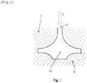
- FIG. 2 shows a cross section on one side of the central axis 5 of the compressor impeller.
- the end section 31 of the disc section in the cross section was cut and polished, and imaged with an optical microscope at 100 ⁇ magnification.
- the end section 31 of the disc section represents 20% of the disc section from the circumference of the disc section of the compressor impeller to the central axis 5 along the radial direction.
- the image was fed to an image analyzer, and measured for the surface density of intermetallic compounds having a circle equivalent size of 1 to 6 ⁇ m, and the surface density of intermetallic compounds having a circle equivalent size of more than 6 ⁇ m.
- Intermetallic compounds at end section of disc section Amounts of refining agent components at end section of disc section Amounts of refining agent components in sections other than end section of disc section High-temperature characteristics
- Productivity Surface density of intermetallic compounds having circle equivalent size of 1 to 6 ⁇ m (Number of intermetallic compounds/mm 2 ) Surface density of intermetallic compounds having circle equivalent size of more than 6 ⁇ m (Number of intermetallic compounds/mm 2 ) Ti content B content Ti content B content Durability test evaluation Casting yield evaluation Percentage of products with internal defects Percentage of products with misrun defects Percentage of products with shrinkage cavity defects (mass%) (mass%) (mass%) (%) (%) (%) (%) (%) Com.
- the refining agent content was measured at the end section of the disc section, and in sections other than the end section of the disc section. 5 g of sample was collected for analysis from the end section 31 of the disc section, the boss section 2, the vane section 4, and the disc section 32 other than the end section shown in FIG. 2 , and the Ti and B contents were analyzed using an ICP emission spectrometer.
- the amounts of the refining agent components in sections other than the end section of the disc section given in Table 2 were calculated as mean values of the refining agent component amounts determined at the boss section, the vane sections, and the disc section other than the end section. The results are presented in Table 2.
- High-temperature fatigue strength was evaluated in a high-temperature durability test (turbo assembly; 150,000 rpm ⁇ 200 h, outlet temperature 200°C). The results are presented in Table 2. The durability test evaluation results in Table 2 followed the following notation.
- Casting yield was evaluated for 1,000 samples produced in each Example. Each sample was tested for external appearance failure due to misruns and shrinkage cavity failure, and internal failure based on the detected internal blow holes in an X-ray examination. The proportions (%) of samples with misruns, shrinkage cavity failure, and internal failure in all samples were determined. The proportion (%) of non-defective products was then determined by subtracting the sum of the proportions of these defective products from the total 100%. The results are presented in Table 2.
- Comparative Example 1 With a high chill temperature, the surface density was low in the intermetallic compounds having a circle equivalent size of 1 to 6 ⁇ m at the end section of the disc section, and was high in the intermetallic compounds having a circle equivalent size of more than 6 ⁇ m at the end section of the disc section. Because of this, fracture occurred at the end section of the disc section, and the sample was inferior in terms of high-temperature characteristics. Further, multiple shrinkage cavity failures occurred at the boss section, and the casting yield was considerably poor.
- Comparative Example 3 there was a decrease in the molten metal temperature. As a result, multiple defects occurred in the appearance of the vane sections due to misruns and shrinkage cavity, and the casting yield was considerably poor. Further, cracking occurred in the vane sections, and the high-temperature characteristics were poor.
- Comparative Example 14 the amounts of the Ti and B components were high in sections other than the end section of the disc section because of the large amounts of the Ti and B components in the molten metal preparation, and the high pour rate of molten metal into the space mold (here and below, "space mold” refers to the product-shape space configured from the plaster mold and the chill). Because of this, fracture occurred in the boss section, and the high-temperature characteristics were poor. There was also a disturbed molten metal flow in the space mold, and the casting yield was considerably poor because of multiple internal failures.
- Comparative Example 16 because of the large amounts of the Ti and B components in the molten metal preparation, the amounts of the Ti and B components were large in the end section of the disc section, and in sections other than the end section of the disc section. This caused aggregation of refining agent particles. Further, fracture occurred in the disc section, and the high-temperature characteristics were poor.
- Comparative Example 19 because of the lateral pour direction of molten metal into the space mold, nonuniform solidification occurred in the circumferential direction of the compressor impeller. This caused cracking in the boss section due to an axial runout, and the high-temperature characteristics were poor. Further, because the molten metal was nonuniformly charged into the space mold, multiple internal failures occurred, and the casting yield was considerably poor.
- Each Al alloy of the composition shown under the column “Components” in Table 3 was melted by using a common molten metal process, and the molten metal was adjusted to the temperature shown in Table 3 by a molten metal preparation step.
- the molten metal preparation step 150 kg of the Al alloy of the composition shown under the column “Components” in Table 3 was melted to obtain a molten metal.
- a blow degassing process was performed by blowing argon gas into the molten metal for 20 minutes with a rotary gas blower operated at a rotation speed of 400 rpm, and a gas flow rate of 2.5 Nm 3 /h. The whole molten metal was held still for 1 hour to remove the slag.
- the Al alloy molten metal prepared in the molten metal preparation step was then subjected to low-pressure casting to produce an Al alloy casting, whereby the molten metal was pressure injected into a predetermined space configured from a plaster mold that had been adjusted to 220°C, and a copper chill that had been adjusted to the temperature shown in Table 3 and disposed on the surface that contacts the impeller disc surface.
- the Al alloy casting was intended as a turbocharger compressor impeller for trucks, and had a shape with a disc section measuring 80 mm in diameter, a boss section measuring 70 mm in height, vane sections measuring 60 mm in height and having 14 vanes that were 0.4 mm in thickness at the vane tip. As shown in FIG.
- the space configured from the plaster mold and the chill was formed by vertically disposing the plaster mold and the chill so that the chill was higher in position than the plaster mold having a molten metal inlet at the bottom.
- the pour direction of molten metal was upward.
- the molten metal was pressure injected into the space at a pour rate of 0.75 m/s at the molten metal inlet, and the pressure was maintained until the whole Al alloy casting solidified.
- the Al alloy casting was removed from the plaster mold, and subjected to a solution treatment under the conditions shown in Table 3, and thereafter an aging treatment under the conditions of Table 3. In this way, a sample Al alloy cast impeller for compressors was prepared.
- Intermetallic compounds at end section of disc section Amounts of refining agent components at end section of disc section Amounts of refining agent components in sections other than end section of disc section High-temperature characteristics
- Productivity Surface density of intermetallic compounds having circle equivalent size of 1 to 6 ⁇ m (Number of intermetallic compounds/mm 2 ) Surface density of intermetallic compounds having circle equivalent size of more than 6 ⁇ m (Number of intermetallic compounds/mm 2 ) Ti content B content Ti content B content Durability test evaluation Casting yield evaluation Percentage of products with internal defects Percentage of products with misrun defects Percentage of products with shrinkage cavity defects (mass %) (mass %) (mass %) (%) (%) (%) (%) (%) (%) (%) (%) (%) (%) (%) (%) (%) (%) (%) (%) (%) (%) (%) (%) (%) (%) (%) (%) (%) (%) (%) Present Ex.
- Comparative Example 21 the molten metal temperature was low, and the casting yield was poor with multiple failures occurring in the appearance of the vane sections due to misruns. Further, cracking occurred in the vane sections, and the high-temperature characteristics were poor.
- Comparative Example 23 With a low chill temperature, multiple misruns occurred in the disc section, and the casting yield was poor. Further, cracking due to misruns occurred in the disc, and the high-temperature characteristics were poor.
- Comparative Example 24 the chill temperature was high, and the surface density was low in the intermetallic compounds having a circle equivalent size of 1 to 6 ⁇ m at the end section of the disc section, and was high in the intermetallic compounds having a circle equivalent size of more than 6 ⁇ m at the end section of the disc section. This caused fractures in the disc section, and the high-temperature characteristics were poor.
- the solution treatment step was not performed in Comparative Example 25.
- the aging treatment step was not performed in Comparative Example 26. As a result, fracture occurred in the disc section, and the high-temperature characteristics were poor.
- Each Al alloy of the composition shown under the column “Components” in Table 5 was melted by using a common molten metal process, and the molten metal was adjusted to the temperature shown in Table 5 by a molten metal preparation step.
- the molten metal preparation step 200 kg of the Al alloy of the composition shown under the column “Components” in Table 5 was melted to obtain a molten metal.
- a blow degassing process was performed by blowing argon gas into the molten metal for 40 minutes with a rotary gas blower operated at a rotation speed of 400 rpm, and a gas flow rate of 2.5 Nm 3 /h. The whole molten metal was held still for 1.5 hours to remove the slag.
- the Al alloy molten metal prepared in the molten metal preparation step was then subjected to low-pressure casting to produce an Al alloy casting, whereby the molten metal was pressure injected into a predetermined space configured from a plaster mold that had been adjusted to 220°C, and a copper chill that had been adjusted to the temperature shown in Table 5 and disposed on the surface that contacts the impeller disc surface.
- the Al alloy casting was intended as a turbocharger compressor impeller for ships, and had a shape with a disc section measuring 150 mm in diameter, a boss section measuring 160 mm in height, vane sections measuring 120 mm in height and having 16 vanes that were 0.6 mm in thickness at the vane tip. As shown in FIG.
- the space configured from the plaster mold and the chill was formed by vertically disposing the plaster mold and the chill so that the chill was higher in position than the plaster mold having a molten metal inlet at the bottom.
- the pour direction of molten metal was upward.
- the molten metal was pressure injected into the space at a pour rate of 0.95 m/s at the molten metal inlet, and the pressure was maintained until the whole Al alloy casting solidified.
- the Al alloy casting was removed from the plaster mold, and subjected to a solution treatment under the conditions shown in Table 5, and thereafter to an aging treatment under the conditions of Table 5. In this way, a sample Al alloy cast impeller for compressors was prepared.
- Intermetallic compounds at end section of disc section Amounts of refining agent components at end section of disc section Amounts of refining agent components in sections other than end section of disc section High-temperature characteristics
- Productivity Surface density of intermetallic compounds having circle equivalent size of 1 to 6 ⁇ m (Number of intermetallic compounds/mm 2 ) Surface density of intermetallic compounds having circle equivalent size of more than 6 ⁇ m (Number of intermetallic compounds/mm 2 ) Ti content B content Ti content B content Durability test evaluation Casting yield evaluation Percentage of products with internal defects Percentage of products with misrun defects Percentage of products with shrinkage cavity defects (mass%) (mass%) (mass%) (%) (%) (%) (%) (%) (%) (%) (%) (%) (%) (%) (%) (%) (%) (%) (%) Present Ex.
- Comparative Example 27 the molten metal temperature was high, and the cooling rate was low.
- the surface density was therefore low in the intermetallic compounds having a circle equivalent size of 1 to 6 ⁇ m at the end section of the disc section, and was high in the intermetallic compounds having a circle equivalent size of more than 6 ⁇ m at the end section of the disc section. This caused multiple failures in the appearance of the boss section due to shrinkage cavity, and the casting yield was considerably poor. Further, fracture occurred in the disc section, and the high-temperature characteristics were poor.
- Comparative Example 28 the molten metal temperature was low, and the casting yield was poor with multiple failures occurring in the appearance of the vane sections due to misruns . Further, cracking occurred in the vane sections, and the high-temperature characteristics were poor.
- Comparative Example 30 the chill temperature was high, and the surface density was low in the intermetallic compounds having a circle equivalent size of 1 to 6 ⁇ m at the end section of the disc section, and was high in the intermetallic compounds having a circle equivalent size of more than 6 ⁇ m at the end section of the disc section. This caused fractures in the disc section, and the high-temperature characteristics were poor.
- the solution treatment step was not performed in Comparative Example 31, and the aging treatment step was not performed in Comparative Example 32. As a result, the disc section was damaged, and high-temperature characteristics was poor.
- the present invention enables inexpensively providing an Al alloy impeller for compressors that has excellent high-temperature strength, and that can stably withstand an increasing of temperatures due to an increasing of number of rotations over extended time periods.
- the present invention is also industrially very effective in that the output power of an internal combustion engine can be improved by increasing the supercharge ability of a turbocharger.
Landscapes
- Engineering & Computer Science (AREA)
- Mechanical Engineering (AREA)
- Chemical & Material Sciences (AREA)
- Materials Engineering (AREA)
- General Engineering & Computer Science (AREA)
- Organic Chemistry (AREA)
- Metallurgy (AREA)
- Physics & Mathematics (AREA)
- Crystallography & Structural Chemistry (AREA)
- Thermal Sciences (AREA)
- Structures Of Non-Positive Displacement Pumps (AREA)
- Supercharger (AREA)
- Mold Materials And Core Materials (AREA)
- Molds, Cores, And Manufacturing Methods Thereof (AREA)
Claims (6)
- Verdichterrad, das aus einer Aluminiumlegierung gegossen ist, mit einem Nabenabschnitt, einer Vielzahl von Flügelabschnitten und einem Scheibenabschnitt,wobei der Nabenabschnitt, die Vielzahl von Flügelabschnitte und der Scheibenabschnitt mit Ausnahme eines Endabschnitts eine Aluminiumlegierung aufweisen, die Cu: 1,4 bis 3,2 Massen-%, Mg: 1,0 bis 2,0 Massen-%, Ni: 0,5 bis 2,0 Massen-%, Fe: 0,5 bis 2,0 Massen-%, Ti: 0,01 bis 0,35 Massen-%, und B: 0,002 bis 0,070 Massen-% und einen Rest von Aluminium und unvermeidbaren Fremdstoffen aufweist,wobei der Endabschnitt des Scheibenabschnitts eine Aluminiumlegierung aufweist, die Cu: 1,4 bis 3,2 Massen-%, Mg: 1,0 bis 2,0 Massen-%, Ni: 0,5 bis 2,0 Massen-%, Fe: 0,5 bis 2,0 Massen-%, Ti: 0,005 bis 0,175 Massen-%, und B: 0,001 bis 0,035 Massen-% und einen Rest von Aluminium und unvermeidbaren Fremdstoffen aufweist, undwobei mindestens 10000/mm2 von intermetallischen Verbindungen mit einem Kreis-äquivalenten Durchmesser von 1 bis 6 µm und nicht mehr als 500/mm2 von intermetallischen Verbindungen mit einem Kreis-äquivalenten Durchmesser, der 6 µm übersteigt, in dem Endabschnitt des Scheibenabschnitts vorkommen.
- Verdichterrad, das aus der Aluminiumlegierung gegossen ist, gemäß Anspruch 1,wobei das Verdichterrad in großtechnischen Anwendungen, die Schiffe enthalten, eingesetzt wird, undwobei der Nabenabschnitt eine Höhe von 200 bis 80 mm hat, der Scheibenabschnitt einen Durchmesser von 300 bis 100 mm hat und die Flügelabschnitte eine Höhe von 180 bis 60 mm haben, mit 30 bis 10 Flügeln, die an der Flügelspitze 4,0 bis 0,4 mm Dicke messen.
- Verdichterrad, das aus der Aluminiumlegierung gegossen ist, gemäß Anspruch 1,wobei das Verdichterrad in Kleinanwendungen, die Automobile enthalten, eingesetzt wird, undwobei der Nabenabschnitt eine Höhe von 100 bis 20 mm hat, der Scheibenabschnitt einen Durchmesser von 120 bis 25 mm hat und die Flügelabschnitte eine Höhe von 90 bis 5 mm haben, mit 20 bis 4 Flügeln, die an der Flügelspitze 3,0 bis 0,1 mm Dicke messen.
- Verfahren zum Herstellen eines Verdichterrads, das aus einer Aluminiumlegierung gegossen ist, das die folgenden Schritte aufweist:Vorbereiten einer 720 bis 780°C Metallschmelze aus Aluminiumlegierung, die Cu: 1,4 bis 3,2 Massen-%, Mg: 1,0 bis 2,0 Massen-%, Ni: 0,5 bis 2,0 Massen-%, Fe: 0,5 bis 2,0 Massen-%, und einen Rest von Aluminium und unvermeidbaren Fremdstoffen aufweist, und Beimengen eines Veredlungsmittels zu einer Metallschmelze aus Aluminiumlegierung, um Ti: 0,01 bis 0,35 Massen-%, und B: 0,002 bis 0,070 Massen-% in die Legierungszusammensetzung einzuarbeiten;Gießen des Aluminiumlegierungsguss durch Druckguss, wodurch die vorbereitete Metallschmelze aus Aluminiumlegierung durch einen Metallschmelzeneinlass in einen Raum eingespritzt wird, der eine Produktform hat, die von einer Gipsform mit dem Metallschmelzeneinlass an dem Boden der Gipsform und einer 100 bis 250°C Kokille gestaltet ist, die an einer Fläche angeordnet ist, die eine Flügelradscheibenfläche kontaktiert, wobei der Raum durch Anordnen der Gipsform und der Kokille ausgebildet wird, sodass die Kokille an einer oberen Position und die Gipsform an einer unteren Position ist und eine Einströmrate an dem Metallschmelzeneinlass in den Raum 0,12 bis 1,00 m/s ist;Lösungsglühen durch Unterziehen des Aluminiumlegierungsgusses einem Lösungsglühen; undAuslagern durch Unterziehen des Aluminiumlegierungsgusses einer Auslagerung nach dem Lösungsglühen.
- Verfahren zum Herstellen des Verdichterrads, das aus der Aluminiumlegierung gegossen ist, gemäß Anspruch 4, wobei der Endabschnitt des Scheibenabschnitts eine Abkühlungsgeschwindigkeit von 0,1 bis 200°C/s in dem Gussschritt hat.
- Verfahren zum Herstellen des Verdichterrads, das aus der Aluminiumlegierung gegossen ist, gemäß Anspruch 4 oder 5,wobei der Aluminiumlegierungsguss für zwei Stunden oder mehr auf einer Temperatur 5 bis 25°C unterhalb der Solidustemperatur der Aluminiumlegierung in dem Lösungsglühschritt wärmebehandelt wird, undwobei der lösungsgeglühte Aluminiumlegierungsguss einer Wärmebehandlung auf 180 bis 230°C für 3 bis 30 Stunden in dem Auslagerungsschritt unterzogen wird.
Applications Claiming Priority (2)
| Application Number | Priority Date | Filing Date | Title |
|---|---|---|---|
| JP2014052840 | 2014-03-15 | ||
| PCT/JP2015/001340 WO2015141191A1 (ja) | 2014-03-15 | 2015-03-11 | Al合金鋳物製コンプレッサーインペラー及びその製造方法 |
Publications (3)
| Publication Number | Publication Date |
|---|---|
| EP3121303A1 EP3121303A1 (de) | 2017-01-25 |
| EP3121303A4 EP3121303A4 (de) | 2017-03-15 |
| EP3121303B1 true EP3121303B1 (de) | 2018-01-03 |
Family
ID=54144175
Family Applications (1)
| Application Number | Title | Priority Date | Filing Date |
|---|---|---|---|
| EP15764543.3A Not-in-force EP3121303B1 (de) | 2014-03-15 | 2015-03-11 | Aus al-legierung gegossenes verdichterlaufrad und verfahren zur herstellung davon |
Country Status (5)
| Country | Link |
|---|---|
| US (1) | US20170107600A1 (de) |
| EP (1) | EP3121303B1 (de) |
| JP (1) | JPWO2015141191A1 (de) |
| CN (1) | CN106170572A (de) |
| WO (1) | WO2015141191A1 (de) |
Families Citing this family (8)
| Publication number | Priority date | Publication date | Assignee | Title |
|---|---|---|---|---|
| DE112014005623T5 (de) * | 2013-12-13 | 2016-09-22 | Showa Denko K.K. | Geformtes Bauteil aus Aluminium für ein Turbokompressorrad und Verfahren zum Herstellen eines Turbokompressorrades |
| CN105382239A (zh) * | 2015-12-21 | 2016-03-09 | 常熟市制冷压缩机铸件厂 | 一种铝合金冰箱压缩机外壳 |
| JP7020031B2 (ja) * | 2017-09-28 | 2022-02-16 | 日本電産株式会社 | インペラ、羽根車、送風装置、及び、送風装置の製造方法 |
| JP2019065359A (ja) * | 2017-10-03 | 2019-04-25 | 株式会社豊田自動織機 | 高温における機械的特性に優れたアルミニウム粉末合金製輸送機用圧縮機部品及びその製造方法 |
| CN108730229B (zh) * | 2018-05-22 | 2020-07-28 | 江苏昊科汽车空调有限公司 | 高强度压缩机叶轮 |
| CN112743044A (zh) * | 2020-12-29 | 2021-05-04 | 上海蓝铸特种合金材料有限公司 | 一种超细晶粒度高温合金叶轮的精密铸造方法 |
| CN114309455B (zh) * | 2021-12-17 | 2023-04-18 | 山东豪迈机械科技股份有限公司 | 一种消除石膏型铸造局部热节的方法 |
| CN116770110A (zh) * | 2023-06-25 | 2023-09-19 | 深圳市爱斯特新材料科技有限公司 | 一种铝合金压铸件及其制备方法 |
Family Cites Families (10)
| Publication number | Priority date | Publication date | Assignee | Title |
|---|---|---|---|---|
| JPS5910459A (ja) * | 1982-07-08 | 1984-01-19 | Honda Motor Co Ltd | 精密鋳造方法 |
| GB2409423B (en) * | 2003-12-23 | 2007-04-11 | Doncasters Ltd | Metal casting apparatus and method |
| JP4290024B2 (ja) * | 2004-01-26 | 2009-07-01 | 古河スカイ株式会社 | 耐熱強度に優れたターボチャージャー用アルミニウム合金鋳物製コンプレッサーインペラー |
| JP2008264846A (ja) * | 2007-04-23 | 2008-11-06 | Hitachi Metal Precision:Kk | 羽根車の製造方法 |
| JP4958292B2 (ja) * | 2007-07-19 | 2012-06-20 | 日立金属株式会社 | アルミニウムダイカスト合金、この合金からなる鋳造コンプレッサ羽根車およびその製造方法 |
| JP2010053743A (ja) * | 2008-08-27 | 2010-03-11 | Hitachi Metals Ltd | ダイカスト製コンプレッサ羽根車 |
| JP5598895B2 (ja) * | 2009-01-14 | 2014-10-01 | 株式会社日立メタルプレシジョン | アルミニウムダイカスト合金、この合金からなる鋳造コンプレッサ羽根車およびその製造方法 |
| JP2012025986A (ja) * | 2010-07-21 | 2012-02-09 | Furukawa-Sky Aluminum Corp | アルミニウム合金鋳物製コンプレッサーインペラー及びその製造方法 |
| JP5415655B1 (ja) * | 2012-10-26 | 2014-02-12 | 株式会社Uacj | Al合金鋳物製コンプレッサーインペラー及びその製造方法 |
| JP2015013301A (ja) * | 2013-07-04 | 2015-01-22 | 株式会社Ihi | コンプレッサインペラの成形装置及び成形方法 |
-
2015
- 2015-03-11 CN CN201580014056.5A patent/CN106170572A/zh active Pending
- 2015-03-11 WO PCT/JP2015/001340 patent/WO2015141191A1/ja not_active Ceased
- 2015-03-11 US US15/125,185 patent/US20170107600A1/en not_active Abandoned
- 2015-03-11 EP EP15764543.3A patent/EP3121303B1/de not_active Not-in-force
- 2015-03-11 JP JP2016508521A patent/JPWO2015141191A1/ja active Pending
Non-Patent Citations (1)
| Title |
|---|
| None * |
Also Published As
| Publication number | Publication date |
|---|---|
| JPWO2015141191A1 (ja) | 2017-04-06 |
| WO2015141191A1 (ja) | 2015-09-24 |
| EP3121303A4 (de) | 2017-03-15 |
| EP3121303A1 (de) | 2017-01-25 |
| US20170107600A1 (en) | 2017-04-20 |
| CN106170572A (zh) | 2016-11-30 |
Similar Documents
| Publication | Publication Date | Title |
|---|---|---|
| EP3121303B1 (de) | Aus al-legierung gegossenes verdichterlaufrad und verfahren zur herstellung davon | |
| EP2913122B1 (de) | Aus al-legierung gegossenes laufrad und verfahren zur herstellung davon | |
| JP4290024B2 (ja) | 耐熱強度に優れたターボチャージャー用アルミニウム合金鋳物製コンプレッサーインペラー | |
| EP1767292B1 (de) | Verfahren zum Giessen einer Aluminiumlegierung mit gesteuerter Erstarrung | |
| JPWO2008001758A1 (ja) | アルミニウム鋳造合金、この合金から成る鋳造コンプレッサ羽根車およびその製造方法 | |
| JP2012025986A (ja) | アルミニウム合金鋳物製コンプレッサーインペラー及びその製造方法 | |
| KR101829292B1 (ko) | 터보차저 및 이를 위한 압축기 휠 | |
| CN106661674A (zh) | Ni基超耐热合金 | |
| JP4958292B2 (ja) | アルミニウムダイカスト合金、この合金からなる鋳造コンプレッサ羽根車およびその製造方法 | |
| JPH11246925A (ja) | 高靱性アルミニウム合金鋳物およびその製造方法 | |
| CN116162813B (zh) | 一种铸造铝合金精炼与变质用喷剂及其使用方法 | |
| Zhu et al. | Semi-solid moulding: Competition to cast and machine from forging in making automotive complex components | |
| JP2009041066A (ja) | 耐熱性に優れたマグネシウムダイカスト部品、鋳造コンプレッサ羽根車およびその製造方法 | |
| JP2015178671A (ja) | 自動車用ターボチャージャのタービンホイール及びその製造方法 | |
| JP4845201B2 (ja) | アルミニウムダイカスト合金およびこれを用いたコンプレッサ羽根車 | |
| CN106244838A (zh) | 铌钛碳复合铝合金变质剂及其制备方法 | |
| JP5083965B2 (ja) | 鋳造コンプレッサ羽根車 | |
| JP5415655B1 (ja) | Al合金鋳物製コンプレッサーインペラー及びその製造方法 | |
| JP2017155268A (ja) | Al合金鋳物製コンプレッサーインペラー | |
| JP2015059531A (ja) | Al合金鋳物製コンプレッサーインペラー及びその製造方法 | |
| JP7729576B2 (ja) | TiAl鋳造合金 | |
| JP2019218612A (ja) | 耐クリープ性に優れたアルミニウム合金鋳物製コンプレッサーインペラー及びその製造方法 | |
| CN111172431B (zh) | 一种小排量涡轮增压器叶轮及其生产工艺 | |
| JP2008088460A (ja) | 高強度アルミニウム鋳造合金およびこれを用いたコンプレッサ羽根車 | |
| Ahmmed et al. | Effect of thermal treatment on tensile properties of vacuum die cast modified aluminum alloy A356 |
Legal Events
| Date | Code | Title | Description |
|---|---|---|---|
| PUAI | Public reference made under article 153(3) epc to a published international application that has entered the european phase |
Free format text: ORIGINAL CODE: 0009012 |
|
| 17P | Request for examination filed |
Effective date: 20160816 |
|
| AK | Designated contracting states |
Kind code of ref document: A1 Designated state(s): AL AT BE BG CH CY CZ DE DK EE ES FI FR GB GR HR HU IE IS IT LI LT LU LV MC MK MT NL NO PL PT RO RS SE SI SK SM TR |
|
| AX | Request for extension of the european patent |
Extension state: BA ME |
|
| A4 | Supplementary search report drawn up and despatched |
Effective date: 20170209 |
|
| RIC1 | Information provided on ipc code assigned before grant |
Ipc: F04D 29/30 20060101ALI20170203BHEP Ipc: F02B 39/00 20060101ALI20170203BHEP Ipc: B22C 9/22 20060101ALI20170203BHEP Ipc: B22C 9/02 20060101ALI20170203BHEP Ipc: C22C 21/12 20060101AFI20170203BHEP Ipc: B22D 18/04 20060101ALI20170203BHEP Ipc: B22D 21/04 20060101ALI20170203BHEP Ipc: C22F 1/057 20060101ALI20170203BHEP |
|
| DAV | Request for validation of the european patent (deleted) | ||
| DAX | Request for extension of the european patent (deleted) | ||
| GRAP | Despatch of communication of intention to grant a patent |
Free format text: ORIGINAL CODE: EPIDOSNIGR1 |
|
| INTG | Intention to grant announced |
Effective date: 20170718 |
|
| GRAS | Grant fee paid |
Free format text: ORIGINAL CODE: EPIDOSNIGR3 |
|
| GRAA | (expected) grant |
Free format text: ORIGINAL CODE: 0009210 |
|
| AK | Designated contracting states |
Kind code of ref document: B1 Designated state(s): AL AT BE BG CH CY CZ DE DK EE ES FI FR GB GR HR HU IE IS IT LI LT LU LV MC MK MT NL NO PL PT RO RS SE SI SK SM TR |
|
| REG | Reference to a national code |
Ref country code: GB Ref legal event code: FG4D |
|
| REG | Reference to a national code |
Ref country code: CH Ref legal event code: EP Ref country code: AT Ref legal event code: REF Ref document number: 960336 Country of ref document: AT Kind code of ref document: T Effective date: 20180115 |
|
| REG | Reference to a national code |
Ref country code: IE Ref legal event code: FG4D |
|
| REG | Reference to a national code |
Ref country code: DE Ref legal event code: R096 Ref document number: 602015007249 Country of ref document: DE |
|
| REG | Reference to a national code |
Ref country code: NL Ref legal event code: MP Effective date: 20180103 |
|
| REG | Reference to a national code |
Ref country code: LT Ref legal event code: MG4D |
|
| PGFP | Annual fee paid to national office [announced via postgrant information from national office to epo] |
Ref country code: IE Payment date: 20180326 Year of fee payment: 4 |
|
| REG | Reference to a national code |
Ref country code: AT Ref legal event code: MK05 Ref document number: 960336 Country of ref document: AT Kind code of ref document: T Effective date: 20180103 |
|
| PG25 | Lapsed in a contracting state [announced via postgrant information from national office to epo] |
Ref country code: NL Free format text: LAPSE BECAUSE OF FAILURE TO SUBMIT A TRANSLATION OF THE DESCRIPTION OR TO PAY THE FEE WITHIN THE PRESCRIBED TIME-LIMIT Effective date: 20180103 |
|
| PG25 | Lapsed in a contracting state [announced via postgrant information from national office to epo] |
Ref country code: FI Free format text: LAPSE BECAUSE OF FAILURE TO SUBMIT A TRANSLATION OF THE DESCRIPTION OR TO PAY THE FEE WITHIN THE PRESCRIBED TIME-LIMIT Effective date: 20180103 Ref country code: HR Free format text: LAPSE BECAUSE OF FAILURE TO SUBMIT A TRANSLATION OF THE DESCRIPTION OR TO PAY THE FEE WITHIN THE PRESCRIBED TIME-LIMIT Effective date: 20180103 Ref country code: NO Free format text: LAPSE BECAUSE OF FAILURE TO SUBMIT A TRANSLATION OF THE DESCRIPTION OR TO PAY THE FEE WITHIN THE PRESCRIBED TIME-LIMIT Effective date: 20180403 Ref country code: ES Free format text: LAPSE BECAUSE OF FAILURE TO SUBMIT A TRANSLATION OF THE DESCRIPTION OR TO PAY THE FEE WITHIN THE PRESCRIBED TIME-LIMIT Effective date: 20180103 Ref country code: LT Free format text: LAPSE BECAUSE OF FAILURE TO SUBMIT A TRANSLATION OF THE DESCRIPTION OR TO PAY THE FEE WITHIN THE PRESCRIBED TIME-LIMIT Effective date: 20180103 Ref country code: CY Free format text: LAPSE BECAUSE OF FAILURE TO SUBMIT A TRANSLATION OF THE DESCRIPTION OR TO PAY THE FEE WITHIN THE PRESCRIBED TIME-LIMIT Effective date: 20180103 |
|
| PG25 | Lapsed in a contracting state [announced via postgrant information from national office to epo] |
Ref country code: GR Free format text: LAPSE BECAUSE OF FAILURE TO SUBMIT A TRANSLATION OF THE DESCRIPTION OR TO PAY THE FEE WITHIN THE PRESCRIBED TIME-LIMIT Effective date: 20180404 Ref country code: PL Free format text: LAPSE BECAUSE OF FAILURE TO SUBMIT A TRANSLATION OF THE DESCRIPTION OR TO PAY THE FEE WITHIN THE PRESCRIBED TIME-LIMIT Effective date: 20180103 Ref country code: BG Free format text: LAPSE BECAUSE OF FAILURE TO SUBMIT A TRANSLATION OF THE DESCRIPTION OR TO PAY THE FEE WITHIN THE PRESCRIBED TIME-LIMIT Effective date: 20180403 Ref country code: RS Free format text: LAPSE BECAUSE OF FAILURE TO SUBMIT A TRANSLATION OF THE DESCRIPTION OR TO PAY THE FEE WITHIN THE PRESCRIBED TIME-LIMIT Effective date: 20180103 Ref country code: IS Free format text: LAPSE BECAUSE OF FAILURE TO SUBMIT A TRANSLATION OF THE DESCRIPTION OR TO PAY THE FEE WITHIN THE PRESCRIBED TIME-LIMIT Effective date: 20180503 Ref country code: SE Free format text: LAPSE BECAUSE OF FAILURE TO SUBMIT A TRANSLATION OF THE DESCRIPTION OR TO PAY THE FEE WITHIN THE PRESCRIBED TIME-LIMIT Effective date: 20180103 Ref country code: LV Free format text: LAPSE BECAUSE OF FAILURE TO SUBMIT A TRANSLATION OF THE DESCRIPTION OR TO PAY THE FEE WITHIN THE PRESCRIBED TIME-LIMIT Effective date: 20180103 Ref country code: AT Free format text: LAPSE BECAUSE OF FAILURE TO SUBMIT A TRANSLATION OF THE DESCRIPTION OR TO PAY THE FEE WITHIN THE PRESCRIBED TIME-LIMIT Effective date: 20180103 |
|
| REG | Reference to a national code |
Ref country code: DE Ref legal event code: R119 Ref document number: 602015007249 Country of ref document: DE |
|
| PG25 | Lapsed in a contracting state [announced via postgrant information from national office to epo] |
Ref country code: EE Free format text: LAPSE BECAUSE OF FAILURE TO SUBMIT A TRANSLATION OF THE DESCRIPTION OR TO PAY THE FEE WITHIN THE PRESCRIBED TIME-LIMIT Effective date: 20180103 Ref country code: AL Free format text: LAPSE BECAUSE OF FAILURE TO SUBMIT A TRANSLATION OF THE DESCRIPTION OR TO PAY THE FEE WITHIN THE PRESCRIBED TIME-LIMIT Effective date: 20180103 Ref country code: IT Free format text: LAPSE BECAUSE OF FAILURE TO SUBMIT A TRANSLATION OF THE DESCRIPTION OR TO PAY THE FEE WITHIN THE PRESCRIBED TIME-LIMIT Effective date: 20180103 |
|
| REG | Reference to a national code |
Ref country code: CH Ref legal event code: PL |
|
| PLBE | No opposition filed within time limit |
Free format text: ORIGINAL CODE: 0009261 |
|
| STAA | Information on the status of an ep patent application or granted ep patent |
Free format text: STATUS: NO OPPOSITION FILED WITHIN TIME LIMIT |
|
| PG25 | Lapsed in a contracting state [announced via postgrant information from national office to epo] |
Ref country code: CZ Free format text: LAPSE BECAUSE OF FAILURE TO SUBMIT A TRANSLATION OF THE DESCRIPTION OR TO PAY THE FEE WITHIN THE PRESCRIBED TIME-LIMIT Effective date: 20180103 Ref country code: MC Free format text: LAPSE BECAUSE OF FAILURE TO SUBMIT A TRANSLATION OF THE DESCRIPTION OR TO PAY THE FEE WITHIN THE PRESCRIBED TIME-LIMIT Effective date: 20180103 Ref country code: SK Free format text: LAPSE BECAUSE OF FAILURE TO SUBMIT A TRANSLATION OF THE DESCRIPTION OR TO PAY THE FEE WITHIN THE PRESCRIBED TIME-LIMIT Effective date: 20180103 Ref country code: DK Free format text: LAPSE BECAUSE OF FAILURE TO SUBMIT A TRANSLATION OF THE DESCRIPTION OR TO PAY THE FEE WITHIN THE PRESCRIBED TIME-LIMIT Effective date: 20180103 Ref country code: SM Free format text: LAPSE BECAUSE OF FAILURE TO SUBMIT A TRANSLATION OF THE DESCRIPTION OR TO PAY THE FEE WITHIN THE PRESCRIBED TIME-LIMIT Effective date: 20180103 |
|
| REG | Reference to a national code |
Ref country code: BE Ref legal event code: MM Effective date: 20180331 |
|
| 26N | No opposition filed |
Effective date: 20181005 |
|
| PG25 | Lapsed in a contracting state [announced via postgrant information from national office to epo] |
Ref country code: LU Free format text: LAPSE BECAUSE OF NON-PAYMENT OF DUE FEES Effective date: 20180311 |
|
| PG25 | Lapsed in a contracting state [announced via postgrant information from national office to epo] |
Ref country code: DE Free format text: LAPSE BECAUSE OF NON-PAYMENT OF DUE FEES Effective date: 20181002 |
|
| PG25 | Lapsed in a contracting state [announced via postgrant information from national office to epo] |
Ref country code: BE Free format text: LAPSE BECAUSE OF NON-PAYMENT OF DUE FEES Effective date: 20180331 Ref country code: CH Free format text: LAPSE BECAUSE OF NON-PAYMENT OF DUE FEES Effective date: 20180331 Ref country code: LI Free format text: LAPSE BECAUSE OF NON-PAYMENT OF DUE FEES Effective date: 20180331 Ref country code: SI Free format text: LAPSE BECAUSE OF FAILURE TO SUBMIT A TRANSLATION OF THE DESCRIPTION OR TO PAY THE FEE WITHIN THE PRESCRIBED TIME-LIMIT Effective date: 20180103 |
|
| PG25 | Lapsed in a contracting state [announced via postgrant information from national office to epo] |
Ref country code: FR Free format text: LAPSE BECAUSE OF NON-PAYMENT OF DUE FEES Effective date: 20180331 |
|
| GBPC | Gb: european patent ceased through non-payment of renewal fee |
Effective date: 20190311 |
|
| PG25 | Lapsed in a contracting state [announced via postgrant information from national office to epo] |
Ref country code: IE Free format text: LAPSE BECAUSE OF NON-PAYMENT OF DUE FEES Effective date: 20190311 Ref country code: GB Free format text: LAPSE BECAUSE OF NON-PAYMENT OF DUE FEES Effective date: 20190311 Ref country code: MT Free format text: LAPSE BECAUSE OF NON-PAYMENT OF DUE FEES Effective date: 20180311 |
|
| PG25 | Lapsed in a contracting state [announced via postgrant information from national office to epo] |
Ref country code: TR Free format text: LAPSE BECAUSE OF FAILURE TO SUBMIT A TRANSLATION OF THE DESCRIPTION OR TO PAY THE FEE WITHIN THE PRESCRIBED TIME-LIMIT Effective date: 20180103 |
|
| PG25 | Lapsed in a contracting state [announced via postgrant information from national office to epo] |
Ref country code: PT Free format text: LAPSE BECAUSE OF FAILURE TO SUBMIT A TRANSLATION OF THE DESCRIPTION OR TO PAY THE FEE WITHIN THE PRESCRIBED TIME-LIMIT Effective date: 20180103 |
|
| PG25 | Lapsed in a contracting state [announced via postgrant information from national office to epo] |
Ref country code: RO Free format text: LAPSE BECAUSE OF FAILURE TO SUBMIT A TRANSLATION OF THE DESCRIPTION OR TO PAY THE FEE WITHIN THE PRESCRIBED TIME-LIMIT Effective date: 20180103 Ref country code: HU Free format text: LAPSE BECAUSE OF FAILURE TO SUBMIT A TRANSLATION OF THE DESCRIPTION OR TO PAY THE FEE WITHIN THE PRESCRIBED TIME-LIMIT; INVALID AB INITIO Effective date: 20150311 Ref country code: MK Free format text: LAPSE BECAUSE OF NON-PAYMENT OF DUE FEES Effective date: 20180103 |