EP3121340B1 - Pointe remplaçable pour un outil de démolition - Google Patents
Pointe remplaçable pour un outil de démolition Download PDFInfo
- Publication number
- EP3121340B1 EP3121340B1 EP15177578.0A EP15177578A EP3121340B1 EP 3121340 B1 EP3121340 B1 EP 3121340B1 EP 15177578 A EP15177578 A EP 15177578A EP 3121340 B1 EP3121340 B1 EP 3121340B1
- Authority
- EP
- European Patent Office
- Prior art keywords
- abutment surface
- adapter
- replaceable tip
- demolition
- sidewall
- Prior art date
- Legal status (The legal status is an assumption and is not a legal conclusion. Google has not performed a legal analysis and makes no representation as to the accuracy of the status listed.)
- Active
Links
Images



Classifications
-
- B—PERFORMING OPERATIONS; TRANSPORTING
- B02—CRUSHING, PULVERISING, OR DISINTEGRATING; PREPARATORY TREATMENT OF GRAIN FOR MILLING
- B02C—CRUSHING, PULVERISING, OR DISINTEGRATING IN GENERAL; MILLING GRAIN
- B02C1/00—Crushing or disintegrating by reciprocating members
- B02C1/02—Jaw crushers or pulverisers
-
- B—PERFORMING OPERATIONS; TRANSPORTING
- B02—CRUSHING, PULVERISING, OR DISINTEGRATING; PREPARATORY TREATMENT OF GRAIN FOR MILLING
- B02C—CRUSHING, PULVERISING, OR DISINTEGRATING IN GENERAL; MILLING GRAIN
- B02C1/00—Crushing or disintegrating by reciprocating members
- B02C1/02—Jaw crushers or pulverisers
- B02C1/10—Shape or construction of jaws
-
- B—PERFORMING OPERATIONS; TRANSPORTING
- B23—MACHINE TOOLS; METAL-WORKING NOT OTHERWISE PROVIDED FOR
- B23D—PLANING; SLOTTING; SHEARING; BROACHING; SAWING; FILING; SCRAPING; LIKE OPERATIONS FOR WORKING METAL BY REMOVING MATERIAL, NOT OTHERWISE PROVIDED FOR
- B23D17/00—Shearing machines or shearing devices cutting by blades pivoted on a single axis
-
- B—PERFORMING OPERATIONS; TRANSPORTING
- B23—MACHINE TOOLS; METAL-WORKING NOT OTHERWISE PROVIDED FOR
- B23D—PLANING; SLOTTING; SHEARING; BROACHING; SAWING; FILING; SCRAPING; LIKE OPERATIONS FOR WORKING METAL BY REMOVING MATERIAL, NOT OTHERWISE PROVIDED FOR
- B23D35/00—Tools for shearing machines or shearing devices; Holders or chucks for shearing tools
- B23D35/002—Means for mounting the cutting members
-
- E—FIXED CONSTRUCTIONS
- E02—HYDRAULIC ENGINEERING; FOUNDATIONS; SOIL SHIFTING
- E02F—DREDGING; SOIL-SHIFTING
- E02F3/00—Dredgers; Soil-shifting machines
- E02F3/04—Dredgers; Soil-shifting machines mechanically-driven
- E02F3/96—Dredgers; Soil-shifting machines mechanically-driven with arrangements for alternate or simultaneous use of different digging elements
- E02F3/965—Dredgers; Soil-shifting machines mechanically-driven with arrangements for alternate or simultaneous use of different digging elements of metal-cutting or concrete-crushing implements
-
- E—FIXED CONSTRUCTIONS
- E02—HYDRAULIC ENGINEERING; FOUNDATIONS; SOIL SHIFTING
- E02F—DREDGING; SOIL-SHIFTING
- E02F9/00—Component parts of dredgers or soil-shifting machines, not restricted to one of the kinds covered by groups E02F3/00 - E02F7/00
- E02F9/28—Small metalwork for digging elements, e.g. teeth scraper bits
- E02F9/2808—Teeth
- E02F9/2816—Mountings therefor
- E02F9/2825—Mountings therefor using adapters
-
- E—FIXED CONSTRUCTIONS
- E04—BUILDING
- E04G—SCAFFOLDING; FORMS; SHUTTERING; BUILDING IMPLEMENTS OR AIDS, OR THEIR USE; HANDLING BUILDING MATERIALS ON THE SITE; REPAIRING, BREAKING-UP OR OTHER WORK ON EXISTING BUILDINGS
- E04G23/00—Working measures on existing buildings
- E04G23/08—Wrecking of buildings
- E04G23/082—Wrecking of buildings using shears, breakers, jaws and the like
-
- B—PERFORMING OPERATIONS; TRANSPORTING
- B02—CRUSHING, PULVERISING, OR DISINTEGRATING; PREPARATORY TREATMENT OF GRAIN FOR MILLING
- B02C—CRUSHING, PULVERISING, OR DISINTEGRATING IN GENERAL; MILLING GRAIN
- B02C2210/00—Codes relating to different types of disintegrating devices
- B02C2210/02—Features for generally used wear parts on beaters, knives, rollers, anvils, linings and the like
-
- B—PERFORMING OPERATIONS; TRANSPORTING
- B23—MACHINE TOOLS; METAL-WORKING NOT OTHERWISE PROVIDED FOR
- B23D—PLANING; SLOTTING; SHEARING; BROACHING; SAWING; FILING; SCRAPING; LIKE OPERATIONS FOR WORKING METAL BY REMOVING MATERIAL, NOT OTHERWISE PROVIDED FOR
- B23D35/00—Tools for shearing machines or shearing devices; Holders or chucks for shearing tools
- B23D35/001—Tools for shearing machines or shearing devices; Holders or chucks for shearing tools cutting members
-
- E—FIXED CONSTRUCTIONS
- E02—HYDRAULIC ENGINEERING; FOUNDATIONS; SOIL SHIFTING
- E02F—DREDGING; SOIL-SHIFTING
- E02F9/00—Component parts of dredgers or soil-shifting machines, not restricted to one of the kinds covered by groups E02F3/00 - E02F7/00
- E02F9/28—Small metalwork for digging elements, e.g. teeth scraper bits
- E02F9/2808—Teeth
- E02F9/2816—Mountings therefor
- E02F9/2833—Retaining means, e.g. pins
Definitions
- First step-up portion 24 may extend substantially longitudinally along the first contact side 20. First step-up portion 24 may extend substantially longitudinally to the first hem 23. First step-up portion 24 may extend in a direction away from the first end 21 to the first hem 23. First step-up portion 24 may extend substantially longitudinally from the first step-down portion 34 to the first hem 23. First step-down portion 34 may extend substantially longitudinally along the first contact side 20. First step-down portion 34 may extend longitudinally to the first end 21. First step-down portion 34 may extend in a direction away from the first hem 23 to the first end 21. First step-down portion 34 may extend substantially longitudinally from the first step-up portion 24 to the first end 21.
- the protruded side may be remote from the third contact surface 44 and adjacent to the opening 48.
- the protruded side may be parallel the third contact surface 44 and perpendicular to the perpendicular to the first contact side 20 and to the second contact side 26.
- the protruded side may have a length of 95 mm to 97 mm.
- the protruded side may have a length of 96 mm.
- the distance between the protruded side and the parallel longer side may be 91 mm to 97 mm.
- the distance between the protruded side and the parallel longer side may be 92.2 mm.
- first and second abutment surfaces 50, 52 may act to direct a resultant demolition force through the replaceable tip 10 to the adapter (not shown).
- the first and second abutment surfaces 50, 52 may act to direct a resultant demolition force through the replaceable tip 10 to the adapter when both the first and second abutment surfaces 50, 52 are in force engagement with the adapter.
- the first and second abutment surfaces 50, 52 may be in force engagement with the adapter when the replaceable tool 10 is subject to demolition forces.
- Replaceable tip 10 may have a channel 60.
- the channel 60 may be defined by the first, second and third contact sides 20, 26, 44.
- the channel 60 may be configured to receive the adapter (not shown) of the demolition tool.
- Channel 60 may be formed on the replaceable tip 10 interiorly relative to the external wear surface 18.
- Recess 46 may be assessable from the channel 60. Recess 46 communicates with the channel 60 through the opening 48.
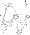
- Figs. 9 and 10 illustrate the replaceable tip 10 on the adapter 64.
- Replaceable tip 10 may cover the support sides 70 and the central side 78 of the adapter 64.
Landscapes
- Engineering & Computer Science (AREA)
- Mechanical Engineering (AREA)
- Structural Engineering (AREA)
- Civil Engineering (AREA)
- Mining & Mineral Resources (AREA)
- General Engineering & Computer Science (AREA)
- Architecture (AREA)
- Food Science & Technology (AREA)
- Chemical & Material Sciences (AREA)
- Chemical Kinetics & Catalysis (AREA)
- Electrochemistry (AREA)
- Crushing And Grinding (AREA)
- Working Measures On Existing Buildindgs (AREA)
- Component Parts Of Construction Machinery (AREA)
Claims (13)
- Pointe remplaçable (10) pour un outil de démolition (94), la pointe remplaçable (10) comprenant :une première paroi latérale (12) ayant un premier côté de contact (20) ;une deuxième paroi latérale (14) ayant un deuxième côté de contact (26) ; etune paroi centrale (16) reliant la première paroi latérale (12) et la deuxième paroi latérale (14), la paroi centrale (16) ayant un troisième côté de contact (44) pourvu d'un évidement (46), l'évidement (46) ayant une première et une deuxième surfaces de butée (50, 52) et le troisième côté de contact (44) ayant une troisième surface de butée (54) adjacente à l'évidement (46) ; etun canal (60) défini par les premier, deuxième et troisième côtés de contact (20, 26, 44), le canal (60) étant configuré pour recevoir un adaptateur (64) de l'outil de démolition (94) caractérisé en ce qu'une première paroi latérale (12), une deuxième paroi latérale (14) et une paroi centrale (16) sont formées comme un corps monolithique, dans laquelle la première surface de butée (50) est sensiblement perpendiculaire à la deuxième surface de butée (52) et dans laquelle les surfaces de butée (50, 52, 54) sont configurées de façon à transférer une force de démolition résultante à l'adaptateur dans une direction perpendiculaire à la première surface de butée (50).
- Pointe remplaçable (10) selon la revendication 1 dans laquelle les première, deuxième et troisième surfaces de butée (50, 52, 54) sont alignées le long d'un axe longitudinal (X) du canal (60).
- Pointe remplaçable (10) selon la revendication 1 ou 2 dans laquelle la première surface de butée (50) est adjacente à la deuxième surface de butée (52).
- Pointe remplaçable (10) selon la revendication 2 dans laquelle la première surface de butée (50) est inclinée vers la deuxième surface de butée (52).
- Pointe remplaçable (10) selon l'une quelconque des revendications précédentes dans laquelle l'évidement (46) a une quatrième surface de butée (56) reliant la deuxième surface de butée (52) à la troisième surface de butée (54).
- Pointe remplaçable (10) selon l'une quelconque des revendications précédentes dans laquelle la première surface de butée (50) est configurée pour agir alternativement avec la deuxième surface de butée (52) ou la troisième surface de butée (54) pour le transfert de la force de démolition résultante à l'adaptateur (64) dans une direction perpendiculaire à la première surface de butée (50).
- Outil de démolition (94) comprenant :un adaptateur (64) monté sur une mâchoire (96) ;une pointe remplaçable (10) selon l'une quelconque des revendications précédentes dans laquelle la pointe remplaçable (10) est couplée à l'adaptateur (64).
- Outil de démolition (94) selon la revendication 7 dans lequel l'adaptateur (64) comprend un corps (66) ayant un côté central (78), le côté central (78) ayant des première, deuxième et troisième surfaces de mise en prise (84, 86, 88) dans lequel le côté central (78) s'étend longitudinalement d'une base (68) à un sommet (83).
- Outil de démolition selon la revendication 8 dans lequel l'adaptateur (64) a une partie saillante (80) s'étendant sensiblement transversalement depuis le corps (66), les première et deuxième surfaces de mise en prise (84, 86) étant fournies sur la partie saillante (80).
- Outil de démolition selon la revendication 8 ou 9 dans lequel l'adaptateur (64) a un épaulement (82) s'étendant sensiblement longitudinalement depuis le corps (66) et étant adjacent à la partie saillante (80) dans lequel la troisième surface de mise en prise (88) est fournie sur l'épaulement (82).
- Procédé de prévention de l'usure sur un adaptateur (64) monté sur un outil de démolition (94), le procédé comprenant les étapes consistant à :fournir une pointe remplaçable selon l'une quelconque des revendications 1 à 6 ;coupler la pointe remplaçable (10) à l'adaptateur (64) comprenant un corps (66) ayant un côté central (78), le côté central (78) ayant des première, deuxième et troisième surfaces de mise en prise (84, 86, 88) dans lequel le côté central (78) s'étend longitudinalement d'une base (68) à un sommet (83), dans lequel la première surface de butée (50) vient en prise de force avec la première surface de mise en prise (84) ; et caractérisé par l'étape consistant àfermer des mâchoires (96, 98) de l'outil de démolition (94) pour écraser un matériau de travail de telle sorte que la force de démolition résultante est dirigée vers l'adaptateur (64) dans une direction perpendiculaire à la première surface de butée (50).
- Procédé selon la revendication 11 dans lequel la deuxième surface de butée (52) vient en prise de force avec la deuxième surface de mise en prise (86) ou la troisième surface de butée (54) vient en prise de force avec les troisièmes surfaces de mise en prise (88).
- Procédé selon la revendication 11 ou 12 dans lequel la fermeture est initiée lorsque les mâchoires (96, 98) sont à une position complètement ouverte par pression hydraulique dans le cylindre hydraulique dans l'outil de démolition (94).
Priority Applications (4)
| Application Number | Priority Date | Filing Date | Title |
|---|---|---|---|
| EP15177578.0A EP3121340B1 (fr) | 2015-07-20 | 2015-07-20 | Pointe remplaçable pour un outil de démolition |
| JP2016140702A JP6723101B2 (ja) | 2015-07-20 | 2016-07-15 | 解体道具用交換可能チップ |
| CN201610567350.5A CN106368259B (zh) | 2015-07-20 | 2016-07-18 | 用于拆毁工具的可替换末端 |
| US15/213,819 US10286400B2 (en) | 2015-07-20 | 2016-07-19 | Removable tip for a demolition jaw |
Applications Claiming Priority (1)
| Application Number | Priority Date | Filing Date | Title |
|---|---|---|---|
| EP15177578.0A EP3121340B1 (fr) | 2015-07-20 | 2015-07-20 | Pointe remplaçable pour un outil de démolition |
Publications (2)
| Publication Number | Publication Date |
|---|---|
| EP3121340A1 EP3121340A1 (fr) | 2017-01-25 |
| EP3121340B1 true EP3121340B1 (fr) | 2020-05-20 |
Family
ID=53724024
Family Applications (1)
| Application Number | Title | Priority Date | Filing Date |
|---|---|---|---|
| EP15177578.0A Active EP3121340B1 (fr) | 2015-07-20 | 2015-07-20 | Pointe remplaçable pour un outil de démolition |
Country Status (4)
| Country | Link |
|---|---|
| US (1) | US10286400B2 (fr) |
| EP (1) | EP3121340B1 (fr) |
| JP (1) | JP6723101B2 (fr) |
| CN (1) | CN106368259B (fr) |
Families Citing this family (7)
| Publication number | Priority date | Publication date | Assignee | Title |
|---|---|---|---|---|
| DE102017108602A1 (de) | 2017-04-21 | 2018-10-25 | Kleemann Gmbh | Brecherbaugruppe für einen Backenbrecher |
| JP6353619B1 (ja) * | 2018-02-27 | 2018-07-04 | 可明 高倉 | 大型飛行機解体用剪断機及び大型飛行機解体用作業車 |
| CN113000099B (zh) * | 2021-02-20 | 2023-01-03 | 临沂恒泰机械制造有限公司 | 一种智能型环保粉碎机 |
| GB2595346B (en) * | 2021-03-24 | 2022-07-06 | Alpha Machine Knife Company Ltd | Single body demolition shear blade |
| CN114012166B (zh) * | 2021-11-01 | 2023-03-10 | 江苏华宏科技股份有限公司 | 板料剪切系统及其锯齿形多刀剪 |
| IT202200021369A1 (it) * | 2022-10-17 | 2023-01-17 | Osa Demolition Equipment S R L | “Cesoia idraulica per acciaio con chela mobile dotata di elementi di assorbimento delle forze di taglio” |
| USD1107762S1 (en) | 2024-07-08 | 2025-12-30 | Caterpillar Inc. | Tip for a ground engaging machine implement |
Citations (2)
| Publication number | Priority date | Publication date | Assignee | Title |
|---|---|---|---|---|
| EP0596285A1 (fr) * | 1992-10-14 | 1994-05-11 | Oyodokomatsu Co., Ltd. | Cisaille à barres d'armatures |
| US20110146469A1 (en) * | 2009-12-18 | 2011-06-23 | Brian Purser | Piercing tip for scrap shear |
Family Cites Families (21)
| Publication number | Priority date | Publication date | Assignee | Title |
|---|---|---|---|---|
| US2707343A (en) | 1949-09-27 | 1955-05-03 | Bucyrus Erie Co | Bucket tooth point and adapter attachment |
| US3624827A (en) | 1968-12-11 | 1971-11-30 | Caterpillar Tractor Co | Earthworking tooth and supporting adapter |
| US3897642A (en) | 1974-05-13 | 1975-08-05 | Caterpillar Tractor Co | Earth working tip and adapter construction |
| ES2088698T3 (es) | 1993-08-30 | 1996-08-16 | Baz Service Ag | Diente excavador. |
| US5423138A (en) | 1994-04-04 | 1995-06-13 | Caterpillar, Inc. | Tip to adapter interface |
| US5561925A (en) | 1995-07-25 | 1996-10-08 | Caterpillar Inc. | Tooth assembly and retaining mechanism |
| US5782019A (en) | 1995-11-29 | 1998-07-21 | H & L Tooth Company | High strength earth working tooth |
| US5709043A (en) * | 1995-12-11 | 1998-01-20 | Esco Corporation | Excavating tooth |
| US6712551B2 (en) * | 2001-11-27 | 2004-03-30 | Caterpillar Inc | Compactor tooth |
| US20040107608A1 (en) * | 2002-12-04 | 2004-06-10 | Thomas Meyers | Improvements in excavator teeth |
| US20070051022A1 (en) * | 2002-12-04 | 2007-03-08 | Thomas Anthony Meyers | Excavator teeth |
| FR2878870B1 (fr) | 2004-12-02 | 2008-12-05 | Predac Sarl | Ensemble d'accouplement entre des pieces d'usure sur des outils supports pour equipement d'engins de travaux publics |
| US20070130776A1 (en) * | 2005-12-12 | 2007-06-14 | Patrick Grant | Shear with replaceable shearing tip |
| JOP20190303A1 (ar) | 2006-02-17 | 2017-06-16 | Esco Group Llc | تجميعة مقاومة للتآكل |
| US8231071B2 (en) * | 2009-08-07 | 2012-07-31 | John R. Ramun | Blade set for jaws used in rail breaking demolition equipment |
| US8628035B2 (en) * | 2009-08-07 | 2014-01-14 | John R. Ramun | Blade set for jaws used in rail breaking demolition equipment |
| US9057177B2 (en) * | 2011-10-08 | 2015-06-16 | Caterpillar Inc. | Implement tooth assembly with tip and adapter |
| US8943716B2 (en) | 2011-10-10 | 2015-02-03 | Caterpillar Inc. | Implement tooth assembly with tip and adapter |
| EP2581506A1 (fr) * | 2011-10-14 | 2013-04-17 | Caterpillar Work Tools B. V. | Élément d'usure pour un outil de démolition |
| PT2983853T (pt) * | 2013-04-09 | 2022-01-06 | Genesis Attachments Llc | Ponta da perfuração e mandíbula superior para uma tesoura de demolição |
| US20150197917A1 (en) * | 2014-01-15 | 2015-07-16 | Caterpillar Inc. | Piercing tip for a shear |
-
2015
- 2015-07-20 EP EP15177578.0A patent/EP3121340B1/fr active Active
-
2016
- 2016-07-15 JP JP2016140702A patent/JP6723101B2/ja active Active
- 2016-07-18 CN CN201610567350.5A patent/CN106368259B/zh active Active
- 2016-07-19 US US15/213,819 patent/US10286400B2/en active Active
Patent Citations (2)
| Publication number | Priority date | Publication date | Assignee | Title |
|---|---|---|---|---|
| EP0596285A1 (fr) * | 1992-10-14 | 1994-05-11 | Oyodokomatsu Co., Ltd. | Cisaille à barres d'armatures |
| US20110146469A1 (en) * | 2009-12-18 | 2011-06-23 | Brian Purser | Piercing tip for scrap shear |
Also Published As
| Publication number | Publication date |
|---|---|
| CN106368259A (zh) | 2017-02-01 |
| JP2017025702A (ja) | 2017-02-02 |
| US20170022725A1 (en) | 2017-01-26 |
| CN106368259B (zh) | 2021-07-16 |
| US10286400B2 (en) | 2019-05-14 |
| EP3121340A1 (fr) | 2017-01-25 |
| JP6723101B2 (ja) | 2020-07-15 |
Similar Documents
| Publication | Publication Date | Title |
|---|---|---|
| US10286400B2 (en) | Removable tip for a demolition jaw | |
| KR102157859B1 (ko) | 파쇄 전단기 및 파쇄 전단기 피어싱 팁 인서트 및 노즈 구성 | |
| RU2510445C2 (ru) | Устройство для присоединения изнашиваемого элемента к переходнику экскаватора и аналогичных машин и его компоненты | |
| JP4558499B2 (ja) | 交換可能なせん断穿孔チップ | |
| CA2875260C (fr) | Pointe a interverrouillage pour du materiel de demolition et de construction | |
| US20140231567A1 (en) | Wear pack for a demolition tool | |
| US20150308076A1 (en) | Demolition adjustable shimable shear tip | |
| US20160348339A1 (en) | Adjustable shimable indexable shear tip | |
| US20150197917A1 (en) | Piercing tip for a shear | |
| US10722894B2 (en) | Tooth block for a demolition tool | |
| US8393660B2 (en) | Gripping member for a work tool | |
| EP1939362B1 (fr) | Outil de travail muni d'une dent amovible montée sur un support de dent | |
| JP6294992B1 (ja) | 小割用破砕機 | |
| US20190283033A1 (en) | Demolition device and utility machine for demolishing a concrete structure | |
| US20140131494A1 (en) | Device For Crushing And/Or Cutting Material, As Well As A Piercing Element, Suitable For Mounting To The Free Nose End Of A Mouth Of Such A Device | |
| US9044815B2 (en) | Keyless coupling arrangement | |
| JP7841714B2 (ja) | カッター刃 | |
| JP2007330870A (ja) | 破砕機 | |
| KR20100011687U (ko) | 철재절단기용 조립식 블레이드의 결합구조 및 그 블레이드 | |
| JP2006219948A (ja) | 破砕機 | |
| JPH0640219U (ja) | 破砕機の牙部材取付構造 | |
| JPH0589709U (ja) | 破砕機における保護装置 |
Legal Events
| Date | Code | Title | Description |
|---|---|---|---|
| PUAI | Public reference made under article 153(3) epc to a published international application that has entered the european phase |
Free format text: ORIGINAL CODE: 0009012 |
|
| STAA | Information on the status of an ep patent application or granted ep patent |
Free format text: STATUS: THE APPLICATION HAS BEEN PUBLISHED |
|
| AK | Designated contracting states |
Kind code of ref document: A1 Designated state(s): AL AT BE BG CH CY CZ DE DK EE ES FI FR GB GR HR HU IE IS IT LI LT LU LV MC MK MT NL NO PL PT RO RS SE SI SK SM TR |
|
| AX | Request for extension of the european patent |
Extension state: BA ME |
|
| STAA | Information on the status of an ep patent application or granted ep patent |
Free format text: STATUS: REQUEST FOR EXAMINATION WAS MADE |
|
| 17P | Request for examination filed |
Effective date: 20170718 |
|
| RBV | Designated contracting states (corrected) |
Designated state(s): AL AT BE BG CH CY CZ DE DK EE ES FI FR GB GR HR HU IE IS IT LI LT LU LV MC MK MT NL NO PL PT RO RS SE SI SK SM TR |
|
| STAA | Information on the status of an ep patent application or granted ep patent |
Free format text: STATUS: EXAMINATION IS IN PROGRESS |
|
| 17Q | First examination report despatched |
Effective date: 20180507 |
|
| GRAP | Despatch of communication of intention to grant a patent |
Free format text: ORIGINAL CODE: EPIDOSNIGR1 |
|
| STAA | Information on the status of an ep patent application or granted ep patent |
Free format text: STATUS: GRANT OF PATENT IS INTENDED |
|
| INTG | Intention to grant announced |
Effective date: 20191211 |
|
| GRAS | Grant fee paid |
Free format text: ORIGINAL CODE: EPIDOSNIGR3 |
|
| GRAA | (expected) grant |
Free format text: ORIGINAL CODE: 0009210 |
|
| STAA | Information on the status of an ep patent application or granted ep patent |
Free format text: STATUS: THE PATENT HAS BEEN GRANTED |
|
| AK | Designated contracting states |
Kind code of ref document: B1 Designated state(s): AL AT BE BG CH CY CZ DE DK EE ES FI FR GB GR HR HU IE IS IT LI LT LU LV MC MK MT NL NO PL PT RO RS SE SI SK SM TR |
|
| REG | Reference to a national code |
Ref country code: GB Ref legal event code: FG4D |
|
| REG | Reference to a national code |
Ref country code: CH Ref legal event code: EP |
|
| REG | Reference to a national code |
Ref country code: DE Ref legal event code: R096 Ref document number: 602015052982 Country of ref document: DE |
|
| REG | Reference to a national code |
Ref country code: AT Ref legal event code: REF Ref document number: 1272673 Country of ref document: AT Kind code of ref document: T Effective date: 20200615 |
|
| REG | Reference to a national code |
Ref country code: LT Ref legal event code: MG4D |
|
| REG | Reference to a national code |
Ref country code: NL Ref legal event code: MP Effective date: 20200520 |
|
| PG25 | Lapsed in a contracting state [announced via postgrant information from national office to epo] |
Ref country code: SE Free format text: LAPSE BECAUSE OF FAILURE TO SUBMIT A TRANSLATION OF THE DESCRIPTION OR TO PAY THE FEE WITHIN THE PRESCRIBED TIME-LIMIT Effective date: 20200520 Ref country code: NO Free format text: LAPSE BECAUSE OF FAILURE TO SUBMIT A TRANSLATION OF THE DESCRIPTION OR TO PAY THE FEE WITHIN THE PRESCRIBED TIME-LIMIT Effective date: 20200820 Ref country code: FI Free format text: LAPSE BECAUSE OF FAILURE TO SUBMIT A TRANSLATION OF THE DESCRIPTION OR TO PAY THE FEE WITHIN THE PRESCRIBED TIME-LIMIT Effective date: 20200520 Ref country code: PT Free format text: LAPSE BECAUSE OF FAILURE TO SUBMIT A TRANSLATION OF THE DESCRIPTION OR TO PAY THE FEE WITHIN THE PRESCRIBED TIME-LIMIT Effective date: 20200921 Ref country code: IS Free format text: LAPSE BECAUSE OF FAILURE TO SUBMIT A TRANSLATION OF THE DESCRIPTION OR TO PAY THE FEE WITHIN THE PRESCRIBED TIME-LIMIT Effective date: 20200920 Ref country code: GR Free format text: LAPSE BECAUSE OF FAILURE TO SUBMIT A TRANSLATION OF THE DESCRIPTION OR TO PAY THE FEE WITHIN THE PRESCRIBED TIME-LIMIT Effective date: 20200821 Ref country code: LT Free format text: LAPSE BECAUSE OF FAILURE TO SUBMIT A TRANSLATION OF THE DESCRIPTION OR TO PAY THE FEE WITHIN THE PRESCRIBED TIME-LIMIT Effective date: 20200520 |
|
| PG25 | Lapsed in a contracting state [announced via postgrant information from national office to epo] |
Ref country code: LV Free format text: LAPSE BECAUSE OF FAILURE TO SUBMIT A TRANSLATION OF THE DESCRIPTION OR TO PAY THE FEE WITHIN THE PRESCRIBED TIME-LIMIT Effective date: 20200520 Ref country code: HR Free format text: LAPSE BECAUSE OF FAILURE TO SUBMIT A TRANSLATION OF THE DESCRIPTION OR TO PAY THE FEE WITHIN THE PRESCRIBED TIME-LIMIT Effective date: 20200520 Ref country code: RS Free format text: LAPSE BECAUSE OF FAILURE TO SUBMIT A TRANSLATION OF THE DESCRIPTION OR TO PAY THE FEE WITHIN THE PRESCRIBED TIME-LIMIT Effective date: 20200520 Ref country code: BG Free format text: LAPSE BECAUSE OF FAILURE TO SUBMIT A TRANSLATION OF THE DESCRIPTION OR TO PAY THE FEE WITHIN THE PRESCRIBED TIME-LIMIT Effective date: 20200820 |
|
| REG | Reference to a national code |
Ref country code: AT Ref legal event code: MK05 Ref document number: 1272673 Country of ref document: AT Kind code of ref document: T Effective date: 20200520 |
|
| PG25 | Lapsed in a contracting state [announced via postgrant information from national office to epo] |
Ref country code: NL Free format text: LAPSE BECAUSE OF FAILURE TO SUBMIT A TRANSLATION OF THE DESCRIPTION OR TO PAY THE FEE WITHIN THE PRESCRIBED TIME-LIMIT Effective date: 20200520 Ref country code: AL Free format text: LAPSE BECAUSE OF FAILURE TO SUBMIT A TRANSLATION OF THE DESCRIPTION OR TO PAY THE FEE WITHIN THE PRESCRIBED TIME-LIMIT Effective date: 20200520 |
|
| PG25 | Lapsed in a contracting state [announced via postgrant information from national office to epo] |
Ref country code: RO Free format text: LAPSE BECAUSE OF FAILURE TO SUBMIT A TRANSLATION OF THE DESCRIPTION OR TO PAY THE FEE WITHIN THE PRESCRIBED TIME-LIMIT Effective date: 20200520 Ref country code: CZ Free format text: LAPSE BECAUSE OF FAILURE TO SUBMIT A TRANSLATION OF THE DESCRIPTION OR TO PAY THE FEE WITHIN THE PRESCRIBED TIME-LIMIT Effective date: 20200520 Ref country code: IT Free format text: LAPSE BECAUSE OF FAILURE TO SUBMIT A TRANSLATION OF THE DESCRIPTION OR TO PAY THE FEE WITHIN THE PRESCRIBED TIME-LIMIT Effective date: 20200520 Ref country code: SM Free format text: LAPSE BECAUSE OF FAILURE TO SUBMIT A TRANSLATION OF THE DESCRIPTION OR TO PAY THE FEE WITHIN THE PRESCRIBED TIME-LIMIT Effective date: 20200520 Ref country code: EE Free format text: LAPSE BECAUSE OF FAILURE TO SUBMIT A TRANSLATION OF THE DESCRIPTION OR TO PAY THE FEE WITHIN THE PRESCRIBED TIME-LIMIT Effective date: 20200520 Ref country code: DK Free format text: LAPSE BECAUSE OF FAILURE TO SUBMIT A TRANSLATION OF THE DESCRIPTION OR TO PAY THE FEE WITHIN THE PRESCRIBED TIME-LIMIT Effective date: 20200520 Ref country code: AT Free format text: LAPSE BECAUSE OF FAILURE TO SUBMIT A TRANSLATION OF THE DESCRIPTION OR TO PAY THE FEE WITHIN THE PRESCRIBED TIME-LIMIT Effective date: 20200520 Ref country code: ES Free format text: LAPSE BECAUSE OF FAILURE TO SUBMIT A TRANSLATION OF THE DESCRIPTION OR TO PAY THE FEE WITHIN THE PRESCRIBED TIME-LIMIT Effective date: 20200520 |
|
| REG | Reference to a national code |
Ref country code: DE Ref legal event code: R097 Ref document number: 602015052982 Country of ref document: DE |
|
| PG25 | Lapsed in a contracting state [announced via postgrant information from national office to epo] |
Ref country code: SK Free format text: LAPSE BECAUSE OF FAILURE TO SUBMIT A TRANSLATION OF THE DESCRIPTION OR TO PAY THE FEE WITHIN THE PRESCRIBED TIME-LIMIT Effective date: 20200520 Ref country code: PL Free format text: LAPSE BECAUSE OF FAILURE TO SUBMIT A TRANSLATION OF THE DESCRIPTION OR TO PAY THE FEE WITHIN THE PRESCRIBED TIME-LIMIT Effective date: 20200520 Ref country code: MC Free format text: LAPSE BECAUSE OF FAILURE TO SUBMIT A TRANSLATION OF THE DESCRIPTION OR TO PAY THE FEE WITHIN THE PRESCRIBED TIME-LIMIT Effective date: 20200520 |
|
| REG | Reference to a national code |
Ref country code: CH Ref legal event code: PL |
|
| PLBE | No opposition filed within time limit |
Free format text: ORIGINAL CODE: 0009261 |
|
| STAA | Information on the status of an ep patent application or granted ep patent |
Free format text: STATUS: NO OPPOSITION FILED WITHIN TIME LIMIT |
|
| 26N | No opposition filed |
Effective date: 20210223 |
|
| REG | Reference to a national code |
Ref country code: BE Ref legal event code: MM Effective date: 20200731 |
|
| PG25 | Lapsed in a contracting state [announced via postgrant information from national office to epo] |
Ref country code: CH Free format text: LAPSE BECAUSE OF NON-PAYMENT OF DUE FEES Effective date: 20200731 Ref country code: LU Free format text: LAPSE BECAUSE OF NON-PAYMENT OF DUE FEES Effective date: 20200720 Ref country code: LI Free format text: LAPSE BECAUSE OF NON-PAYMENT OF DUE FEES Effective date: 20200731 |
|
| PG25 | Lapsed in a contracting state [announced via postgrant information from national office to epo] |
Ref country code: BE Free format text: LAPSE BECAUSE OF NON-PAYMENT OF DUE FEES Effective date: 20200731 Ref country code: SI Free format text: LAPSE BECAUSE OF FAILURE TO SUBMIT A TRANSLATION OF THE DESCRIPTION OR TO PAY THE FEE WITHIN THE PRESCRIBED TIME-LIMIT Effective date: 20200520 |
|
| PG25 | Lapsed in a contracting state [announced via postgrant information from national office to epo] |
Ref country code: IE Free format text: LAPSE BECAUSE OF NON-PAYMENT OF DUE FEES Effective date: 20200720 |
|
| PG25 | Lapsed in a contracting state [announced via postgrant information from national office to epo] |
Ref country code: TR Free format text: LAPSE BECAUSE OF FAILURE TO SUBMIT A TRANSLATION OF THE DESCRIPTION OR TO PAY THE FEE WITHIN THE PRESCRIBED TIME-LIMIT Effective date: 20200520 Ref country code: MT Free format text: LAPSE BECAUSE OF FAILURE TO SUBMIT A TRANSLATION OF THE DESCRIPTION OR TO PAY THE FEE WITHIN THE PRESCRIBED TIME-LIMIT Effective date: 20200520 Ref country code: CY Free format text: LAPSE BECAUSE OF FAILURE TO SUBMIT A TRANSLATION OF THE DESCRIPTION OR TO PAY THE FEE WITHIN THE PRESCRIBED TIME-LIMIT Effective date: 20200520 |
|
| PG25 | Lapsed in a contracting state [announced via postgrant information from national office to epo] |
Ref country code: MK Free format text: LAPSE BECAUSE OF FAILURE TO SUBMIT A TRANSLATION OF THE DESCRIPTION OR TO PAY THE FEE WITHIN THE PRESCRIBED TIME-LIMIT Effective date: 20200520 |
|
| P01 | Opt-out of the competence of the unified patent court (upc) registered |
Effective date: 20230517 |
|
| PGFP | Annual fee paid to national office [announced via postgrant information from national office to epo] |
Ref country code: GB Payment date: 20250619 Year of fee payment: 11 |
|
| PGFP | Annual fee paid to national office [announced via postgrant information from national office to epo] |
Ref country code: FR Payment date: 20250620 Year of fee payment: 11 |
|
| PGFP | Annual fee paid to national office [announced via postgrant information from national office to epo] |
Ref country code: DE Payment date: 20250620 Year of fee payment: 11 |