EP3121363B1 - Equerre de fixation pour cadres constitués de profilés - Google Patents
Equerre de fixation pour cadres constitués de profilés Download PDFInfo
- Publication number
- EP3121363B1 EP3121363B1 EP16178732.0A EP16178732A EP3121363B1 EP 3121363 B1 EP3121363 B1 EP 3121363B1 EP 16178732 A EP16178732 A EP 16178732A EP 3121363 B1 EP3121363 B1 EP 3121363B1
- Authority
- EP
- European Patent Office
- Prior art keywords
- profile
- wing
- shaped groove
- frame
- width
- Prior art date
- Legal status (The legal status is an assumption and is not a legal conclusion. Google has not performed a legal analysis and makes no representation as to the accuracy of the status listed.)
- Active
Links
Images


Classifications
-
- E—FIXED CONSTRUCTIONS
- E06—DOORS, WINDOWS, SHUTTERS, OR ROLLER BLINDS IN GENERAL; LADDERS
- E06B—FIXED OR MOVABLE CLOSURES FOR OPENINGS IN BUILDINGS, VEHICLES, FENCES OR LIKE ENCLOSURES IN GENERAL, e.g. DOORS, WINDOWS, BLINDS, GATES
- E06B3/00—Window sashes, door leaves, or like elements for closing wall or like openings; Layout of fixed or moving closures, e.g. windows in wall or like openings; Features of rigidly-mounted outer frames relating to the mounting of wing frames
- E06B3/96—Corner joints or edge joints for windows, doors, or the like frames or wings
- E06B3/964—Corner joints or edge joints for windows, doors, or the like frames or wings using separate connection pieces, e.g. T-connection pieces
- E06B3/9642—Butt type joints with at least one frame member cut off square; T-shape joints
-
- E—FIXED CONSTRUCTIONS
- E06—DOORS, WINDOWS, SHUTTERS, OR ROLLER BLINDS IN GENERAL; LADDERS
- E06B—FIXED OR MOVABLE CLOSURES FOR OPENINGS IN BUILDINGS, VEHICLES, FENCES OR LIKE ENCLOSURES IN GENERAL, e.g. DOORS, WINDOWS, BLINDS, GATES
- E06B3/00—Window sashes, door leaves, or like elements for closing wall or like openings; Layout of fixed or moving closures, e.g. windows in wall or like openings; Features of rigidly-mounted outer frames relating to the mounting of wing frames
- E06B3/96—Corner joints or edge joints for windows, doors, or the like frames or wings
- E06B3/964—Corner joints or edge joints for windows, doors, or the like frames or wings using separate connection pieces, e.g. T-connection pieces
- E06B3/968—Corner joints or edge joints for windows, doors, or the like frames or wings using separate connection pieces, e.g. T-connection pieces characterised by the way the connecting pieces are fixed in or on the frame members
- E06B3/972—Corner joints or edge joints for windows, doors, or the like frames or wings using separate connection pieces, e.g. T-connection pieces characterised by the way the connecting pieces are fixed in or on the frame members by increasing the cross-section of the connecting pieces, e.g. by expanding the connecting pieces with wedges
-
- E—FIXED CONSTRUCTIONS
- E06—DOORS, WINDOWS, SHUTTERS, OR ROLLER BLINDS IN GENERAL; LADDERS
- E06B—FIXED OR MOVABLE CLOSURES FOR OPENINGS IN BUILDINGS, VEHICLES, FENCES OR LIKE ENCLOSURES IN GENERAL, e.g. DOORS, WINDOWS, BLINDS, GATES
- E06B3/00—Window sashes, door leaves, or like elements for closing wall or like openings; Layout of fixed or moving closures, e.g. windows in wall or like openings; Features of rigidly-mounted outer frames relating to the mounting of wing frames
- E06B3/96—Corner joints or edge joints for windows, doors, or the like frames or wings
- E06B3/988—Corner joints or edge joints for windows, doors, or the like frames or wings specially adapted for sheet metal frame members with an open U-shaped cross-section
Definitions
- the present patent application for industrial invention relates to a fixing square for frame comprising profiles inserted in the square channel.
- the invention relates to the sector of fixing means for door and window frames, i.e. for architectural elements realized to close the openings obtained in masonry walls.
- the fixing square that is the object of the present invention is used to connect two profiles of a frame disposed in such manner to form a "T", to which two glass-stops are fitted; said fixing square comprises two plates in orthogonal position, each plate being intended to be inserted inside a profile.
- T-shaped frames for door and window are composed of two profiles, each profile comprising an external lateral surface and a “T"-longitudinal groove provided on said external lateral surface; said "T"-shaped groove comprises a rectangular base housing and a reduced longitudinal opening.
- said groove is axially accessible through two axial openings, each of them being disposed in proximal position to the free end section of the profile.
- Said end section of the profile is intended to be stopped against the external lateral surface of the other profile, in correspondence of the "T"-shaped groove of the latter profile in such manner that said two grooves are aligned.
- the "T"-shaped frame comprises a fixing square, which comprises a first wing and a second wing, which are perpendicular and have the same width and height as the base housing of the "T"-shaped groove of the profiles.
- each wing is such to position the wing inside the base housing of the "T"-shaped groove of the corresponding profile, being axially inserted inside said base housing and crossing one of the two axial openings of the "T"-shaped groove.
- the mounting of a "T"-shaped frame provides for axially inserting a wing of the fixing square in the "T"-shaped groove, making said fixing square slide until it reaches the desired position; successively, the other wing of the fixing screw is inserted in the axial opening of the "T"-shaped groove provided on the other profile.
- the insertion of the fixing square must occur before the profiles are in the final position, because when the first profile is positioned perpendicularly to the second profile, with its free end section stopped against the lateral surface of the second profile, the latter indirectly covers the axial opening of the first profile.
- the "T"-shaped grooves of said profiles are intended to act as fixing housings for devices, commonly known as glass-stop, each of them being intended to be fitted to a "T"-shaped groove of a profile in order to obtain a stop edge for a glass positioned in the window or door frame.
- said glass-stop device (hereinafter simply defined as “glass-stop”) comprises elastic tabs that are fitted on the edges of the opening of the "T"-shaped groove of a profile and extend inside the "T"-shaped groove.
- the glass-stop fitted to the first profile and the glass-stop fitted to the second profile need to be stopped one against the other in such manner to be positioned orthogonally and uninterruptedly one after the other; more precisely, in case of a quadrangular glass, said glass is supported by a perimeter frame composed of four profiles that are mounted perpendicularly and consecutively, with the four edges of the glass stopped against said four profiles; in such a case the glass is kept in the chosen position by means of a frame composed of four consecutive perpendicular glass-stops, each of them being fixed on the side of the corresponding profile facing towards the glass.
- DE202013009756 discloses a fixing square intended to connect two profiles of a frame and comprising two wings, each wing being provided with an eccentric locking means configured in such manner to let the total width of the wing increase.
- US3375029 discloses a frame comprising two profiles and one fixing square disposed between said two profiles.
- the main purpose of the present invention is to overcome the aforementioned drawbacks of the prior art by disclosing a fixing square that simplifies the mounting, dismounting and blocking operations.
- Another purpose is to disclose a fixing square that, in addition to satisfying the aforementioned purpose, allows for fitting two glass-stops to two profiles connected by said fixing square and positioning said glass-stops in consecutive adjacent position in such manner that they are stopped and positioned uninterruptedly, one after the other, in correspondence of the fixing square.
- the frame of the invention comprises:
- the peculiarity of the frame consists in the fact that at least one wing of the fixing square has a lower width than the longitudinal opening of the "T"-shaped groove wherein it is inserted.
- Said at least one wing of the fixing square comprises an eccentric locking means configured in such manner to let the total length of the wing increase until a width at least equal to the width of the base housing wherein the wing is inserted.
- the advantage obtained by reducing the width of the wings of the fixing square and by inserting the eccentric locking means is the simplification of the mounting operations of the profiles and of the fixing square, inserting said wings into the longitudinal openings of the "T"-shaped grooves of the profiles, and then actuating the fixing means that, by increasing the total width of the wing, prevents the wing from moving inside the base housing of the groove or from coming out backwards through the axial opening.
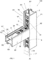
- the frame (100) of the invention comprises a first profile (P1) and a second profile (P2) connected to the first profile (P1).
- the first profile (P1) has a "T"-shaped longitudinal groove (S1) provided on one external lateral surface (B1).
- Such "T"-shaped groove (S1) of the first profile (P1) is sectionally provided with a base housing (1) having a width (L1) and a longitudinal opening (1a) with width (L1a).
- the second profile (P2) has a first "T"-shaped longitudinal groove (S2) obtained on one external lateral surface (B2).
- Such first "T"-shaped groove (S1) of the second profile (P2) is sectionally provided with a base housing (2) having a width (L2) and a longitudinal opening (2a) with width (L2a).
- the second profile (P2) has an end section (C) where the first "T"-shaped groove (S2) of the second profile (P2) ends.
- Such end section (C) is stopped against the external lateral surface (B1) of the first profile (P1) in correspondence of the "T"-shaped groove (S1) of the first profile (P1), in such manner that the "T"-shaped groove of the first profile (P1) and the first "T”-shaped groove of the second profile (P2) are mutually aligned.
- the second profile (P2) has a second "T"-shaped longitudinal groove (S3) provided on the external lateral surface (B2) in opposite position to the first "T"-shaped groove (S2) of the second profile (P2).
- Such second "T"-shaped groove (S3) of the second profile ends on the end section (C) of the second profile.
- the second "T"-shaped groove (S3) of the second profile (P2) and the “T"-shaped groove (S1) of the first profile (P1) are mutually aligned.
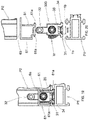
- a first embodiment of a fixing square (3) disposed between the two profiles (P1, P2) is disclosed.
- the fixing square (3) comprises a first wing (31) and a second wing (32) that are mutually inclined.
- the first wing (31) of the fixing square (3) is disposed inside the base housing (1) of the "T"-shaped groove (S1) of the first profile (P1).
- the second wing (32) of the fixing square (3) is disposed inside the base housing (2) of the first "T"-shaped groove (S2) of the second profile (P2).
- the first profile (P1) has a longitudinal axis (A1) that is orthogonal to the longitudinal axis (A2) of the first profile and the two wings (31, 32) of the fixing square (3) are mutually orthogonal.
- Each wing (31, 32) of the fixing square (3) has an internal side (FI) facing towards the profile (P1, P2) and an external side (FE) opposite to the internal side (FI).
- Each wing (31, 32) of the fixing square (3) has a width (L31, L32) lower than the width (L1a, L2a) of the longitudinal opening (1a, 2a) of the "T"-shaped groove (S1, S2) wherein it is inserted.
- the frame (100) comprises a second fixing square (3) inserted in the second "T"-shaped groove (S3) of the second profile (P2) and in the "T"-shaped groove (S1) of the first profile (P1).
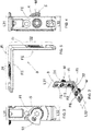
- each wing (31, 32) of the fixing square (3) comprises an eccentric locking means (M) that consists in a screw inserted in a hole provided on the wing (31, 32).
- Such eccentric locking means (M) is shaped in such a way to let the total width of the wing (31, 32) increase until it reaches a width at least equal to the width (L1, L2) of the base housing (1, 2) where the wing (31, 32) of the fixing square (3) is inserted.
- the screw of the eccentric locking means (M) comprises a head (4) disposed in correspondence of the external side (FE) of the wing (31, 32), preferably flush with said external side (FE). Moreover, such screw comprises a stem joined with the head (4) and an eccentric plate (5) fixed to an end of the stem and flush to the internal side (FI) of the wing (31, 32).
- Such eccentric plate (5) can be in an idle position, wherein it does not protrude laterally from the wing (31, 32), and in an operating position, wherein it protrudes laterally from the wing (31, 32), as shown in Figs. 2, 3 and 4 .
- the eccentric plate (5) has a knurled free edge (51) that interferes with the walls of the base housing (1, 2) of the groove (S, S2, S3) inside which the wing (31, 32) is disposed.
- the two wings (31, 32) of the fixing square have a hole (F1, F2) and the frame (100) advantageously comprises a self-drilling and self-tapping screw (V1) inserted in the hole (F1, F2) and screwed on the profile (P1, P2).
- V1 self-drilling and self-tapping screw
- the head of said screw (V1) is tapered, just like the hole (F1, F2) that houses the screw (V1).
- the holes (F1, F2) of the wings (31, 32) of the fixing square (3) are elongated and have a longitudinal axis that is parallel or coinciding with the wing.
- the fixing square of the invention can be also adjusted to frames with other configurations, such as cross frame, "Z"-shaped frames, "X"-shaped frames, etc.
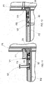
- a second embodiment of the fixing square (300) is disclosed, wherein the eccentric locking means (M) is mounted only on the second wing (32) of the fixing square (300).
- the first wing (31) of the fixing square comprises a portion (34) with increased width and a portion (35) with reduced width.
- the increased portion (34) and the reduced portion (35) protrude in opposite directions from the first wing (31) of the fixing square (300).
- the first wing (31) of the fixing square (300) has a longitudinal axis (D-D).
- the increased portion (34) is shaped as a rectangular plate and is provided with a pair of parallel long sides (36), a pair of parallel short sides (37) and a thickness (H34), as indicated in Figs. 8 and 9 .
- the short sides (37) have a length (L37).
- the increased portion (34) has a higher width (W34) than the width (L32) of the second wing (32) and is identical to the width (L1) of the "T"-shaped groove (S1) of the first profile (P1) wherein it is inserted.
- the reduced portion (35) has a lower width (W35) than the width (W34) of the increased portion (34).
- the thickness (H34) of the increased portion (34) has a value that is identical to or lower than the depth (H1) of the "T"-shaped groove (S1) of the first profile (P1) wherein it is inserted.
- the pair of parallel long sides (36) comprises a long front side (36a) from which the reduced portion (35) protrudes, and a long back side (36b) facing the side opposite to the reduced portion (35).
- the long front side (36a) is coplanar to the external side (FE) of the second wing (32).
- the reduced portion (35) has a pair of parallel sides (38), which are perpendicular to the long front side (36a).
- the parallel sides have a length (L38).
- the total length (L31) is obtained from adding the length (L38) of the parallel sides (38) of the reduced portion (35) with the length (L37) of the short parallel sides (37) of the increased portion (34).
- the total length (L31) of the first wing (31) is lower than the width (L1a) of the opening (1a) of the "T"-shaped groove (S1) of the first profile (P1) wherein said first wing (31) is inserted.
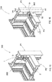
- the increased portion (34) of the first wing (31) of the fixing square (300) comprises a lateral rounded edge (39) in order to let the fixing square (300) rotate inside the "T"-shaped groove (S1) of the first profile (P1), as shown in Fig. 14 .
- the rotation of the fixing square provides that the fixing square (300) goes from a position wherein the longitudinal axis (D-D) of the first wing (31) is transverse with respect to the longitudinal axis (A1-A1) of the first profile (P1), to a position (see Fig. 15 ) wherein the longitudinal axis (D-D) of the first wing (31) is parallel to the longitudinal axis (A1-A1) of the first profile (P1) and the internal side (FI) of the second wing (32) of the fixing square (300) is faced towards the base housing (2) of the first "T"-shaped groove (S2) of the second profile (P2).
- the frame (100) comprises a first glass-stop (6a) fixed to the first profile (P1) and a second glass-stop (6b) fixed to the second profile (P2).
- each glass-stop (6a, 6b) comprises:
- a transverse end section (62) of the first glass-stop (6a) is stopped against the second profile (P2), whereas the transverse end section (62) of the second glass-stop (6b) is stopped against the main wall (63) of the first glass-stop (6a).
- the reduced portion (35) of the first wing (31) of the fixing square (300) is disposed between the tabs (61).
- the reduced portion (35) of the first wing (31) of the fixing square (300) has a lower width (W35) than the internal distance (W61a) between the hook-shaped end sections (61a) of the tabs (61) of the glass-stop (6a, 6b), as shown in Fig. 20 .
- the second wing (32) of the fixing square (300) has a lower width (L32) than the width (L2a) of the longitudinal opening (2a) of the first "T"-shaped groove (S2) of the second profile (P2) wherein it is inserted.
- the fixing square (300) is prevented from coming out from the base housing (1) of the "T"-shaped groove (S2) of the first profile (P1).
- the first glass-stop (6a) can be inserted in the first profile (P1) and positioned in such manner that said first glass-stop (6a) is stopped against the second profile (P2).
- the second glass-stop (6b) can be inserted in the second profile and stopped against the main wall (63) of the first glass-stop (6a).
- the glass-stops (6a, 6b) can be positioned in the profiles (P1, P2) and stopped mutually, in orthogonal position without interruption, even if the fixing square (300) is inserted in the "T"-shaped groove.
Landscapes
- Engineering & Computer Science (AREA)
- Civil Engineering (AREA)
- Structural Engineering (AREA)
- Mutual Connection Of Rods And Tubes (AREA)
- Securing Of Glass Panes Or The Like (AREA)
Claims (16)
- Châssis (100) comprenant :- un premier profilé (P1) ayant un axe longitudinal (A1-A1), au moins une surface latérale extérieure (B1) et une rainure en « T » (S1) longitudinale prévue sur ladite au moins une surface latérale extérieure (B1) ; ladite rainure en « T » (S1) présentant un siège de base (1) ayant une largeur (L1) et une embouchure longitudinale (1a) ayant une largeur de (L1a) ;- un second profilé (P2) ayant un axe longitudinal (A2-A2), au moins une surface latérale extérieure (B2) et une première rainure en « T » (S2) longitudinale prévue sur ladite au moins une surface latérale extérieure (B2) ; ladite première rainure en « T » (S2) présentant un siège de base (2) ayant une largeur (L2) et une embouchure longitudinale (2a) ayant une largeur (L2a) ; ledit second profilé (P2) présentant une section d'extrémité (C), sur laquelle débouche ladite première rainure en « T » (S2) ; ladite section d'extrémité (C) étant en butée contre la surface latérale extérieure (B1) du dit premier profilé (P1) en correspondance de la rainure en « T » (S2) du premier profilé (P1) ; ladite première rainure en « T » (S2) du second profilé (P2) et ladite rainure en « T » (S1) du dit premier profilé (P1) étant alignées entre elles ;- une équerre de fixation (3; 300) entre lesdits deux profilés (P1,P2) ; ladite équerre de fixation (3; 300) comprenant une première aile (31) et une seconde aile (32) inclinées l'une par rapport à l'autre ; ladite première aile (31) étant disposée à l'intérieur du dit siège de base (1) de la rainure en « T » (S1) du dit premier profilé (P1) ; ladite seconde aile (32) étant disposée à l'intérieur du dit siège de base (2) de la première rainure en « T » (S2) du dit second profilé (P2); chaque aile (31, 32) présentant une face interne (FI), orientée vers le profilé et une face externe (FE), opposée à celle interne (FI);châssis caractérisé en ce qu'au moins une aile (31, 32) de l'équerre de fixation (3; 300) présente une largeur (L31, L32) inférieure par rapport à la largeur (L1a, L2a) de l'embouchure longitudinale (1a,2a) de la rainure en « T » (S1,S2) dans laquelle elle est insérée ; ladite au moins une aile (31, 32) de ladite équerre de fixation (3; 300) comprenant un moyen de blocage excentrique (M) façonné de manière telle à permettre l'augmentation de la largeur globale de l'aile (31, 32) jusqu'à une largeur au moins égale à la largeur (L1, L2) du siège de base (1, 2) dans lequel l'aile (31, 32) est insérée.
- Châssis selon la revendication 1, où ledit moyen de blocage excentrique (M) comprend une vis enfilée à l'intérieur d'un orifice prévu sur l'aile correspondante (31, 32) ; ladite vis comprenant :- une tête (4) disposée en correspondance de la face externe (FE) de l'aile (31, 32), préférablement à ras de ladite face externe (FE) ;- une tige, solidaire avec ladite tête (4) et qui se termine par une extrémité libre ;- une plaquette excentrique (5), fixée sur l'extrémité libre de ladite tige et disposée à ras de la face interne (FI) de l'aile (31, 32) ; ladite plaquette excentrique (5) pouvant assumer une assiette de repos, où elle ne déborde pas latéralement par rapport à l'aile (31, 32), et une assiette opérationnelle où elle déborde latéralement par rapport à l'aile (31, 32) ; ladite plaquette excentrique (5) présentant un bord libre (51) qui interfère avec les parois du siège de base (1,2) de la rainure dans laquelle l'aile (31, 32) est disposée.
- Châssis (100) selon la revendication 2, où ledit bord libre (51) de ladite plaquette excentrique (5) est moleté.
- Châssis (100) selon l'une quelconque des revendications précédentes, où au moins l'une des dites deux ailes (31, 32) présente un orifice (F1, F2) ; ledit châssis comprenant une vis (V1) insérée à l'intérieur du dit orifice (F1, F2) et vissée sur le profilé correspondant (P1, P2).
- Châssis (100) selon la revendication 4, où ladite vis est auto-perforante/autotaraudeuse.
- Châssis (100) selon la revendication 4 ou 5, où la tête de ladite vis (V1) est disposée à ras par rapport à la face externe (FE) de l'aile correspondante (31, 32).
- Châssis (100) selon l'une quelconque des revendications de 4 à 6, où ladite tête de dite vis (V1) est évasée et l'orifice (F1, F2) est évasé.
- Châssis (100) selon l'une quelconque des revendications de 4 à 7, où ledit orifice (F1, F2) résulte allongé et présente un axe longitudinal parallèle ou coïncidant avec celui de l'aile (31, 32).
- Châssis (100) selon l'une quelconque des revendications précédentes, où ledit second profilé (P2) présente une seconde rainure en « T » (S3) longitudinale prévue sur ladite au moins une surface latérale externe (B2) en position opposée par rapport à la première rainure en « T » (S2) du dit second profilé (P2) ; ladite seconde rainure en « T » (S3) débouchant sur la section d'extrémité (C) ; ladite seconde rainure en « T » (S3) du second profilé (P2) et ladite rainure en « T » (S1) du dit premier profilé (P1) étant alignées entre elles; ledit châssis comprenant une seconde équerre de fixation (3; 300) enfilée à l'intérieur de ladite seconde rainure en « T » (S3) du second profilé (P2) et à l'intérieur de dite rainure en « T » (S1) du dit premier profilé (P1).
- Châssis (100) selon l'une des revendications précédentes, où les axes (A1-A1 ; A2-A2) des profilés sont orthogonaux entre eux et les deux ailes (31, 32) de l'équerre de fixation (3; 300) sont orthogonales entre elles.
- Châssis (100) selon la revendication indépendante 1, où ledit moyen de blocage excentrique (M) est monté uniquement sur la seconde aile (32) de l'équerre de fixation (300) ;
ladite première aile (31) de l'équerre de fixation (300) comprenant une portion majorée (34), en forme de plaque rectangulaire ayant une largeur (W34), et une portion réduite (35) ayant une largeur (W35), mineure par rapport à la largeur (W34) de la portion majorée (34) ;
où la portion majorée (34) et la portion réduite (35) débordent en directions opposées de ladite première aile (31) ;
ladite portion majorée (34) de la première aile (31) ayant une largeur (W34) majeure de la largeur (L32) de la seconde aile (32) et égale à la largeur (L1) de la rainure en « T » (S1) du premier profilé (P1) ;
ladite rainure en « T » (S1) du premier profilé (P1) ayant une profondeur (H1) ;
et ladite portion majorée (34) de la première aile (31) ayant une épaisseur (H34) égale à la profondeur (H1) de la rainure en « T » (S1) du premier profilé (P1). - Châssis selon la revendication 11, où ladite portion majorée (34) comprend une paire de côtés longs (36) parallèles entre eux et une paire de côtés courts (37) parallèles entre eux et ayant une longueur (L37) ; ladite paire de côtés longs (36) parallèles comprenant un côté long antérieur (36a), duquel déborde ladite portion réduite (35), et un côté long postérieur (36b) orienté vers le côté opposé à ladite portion réduite (35) ; ledit côté long antérieur (36a) étant coplanaire par rapport à la face externe (FE) de la seconde aile (32).
- Châssis (100) selon la revendication 12, où ladite portion réduite (35) présente une paire de côtés parallèles (38) entre eux, qui sont perpendiculaires au côté long antérieur (36a) et ont une longueur (L38) ; la longueur totale (L31) de la première aile (31) de l'équerre de fixation (300) est donnée par la somme de la longueur (L38) des dits côtés parallèles (38) de la portion réduite (35) et par la longueur (L37) des côtés parallèles courts (37) de la portion majorée (34) ; ladite longueur totale (L31) étant mineure de la largeur (L1a) de l'embouchure (1a) de la rainure en « T » (S1) du premier profilé (P1) dans lequel ladite première aile (31) est insérée.
- Châssis selon l'une quelconque des revendications de 11 à 13, comprenant au moins un dispositif de blocage de vitre (6a, 6b) accroché au profilé (P1, P2) ; ledit dispositif de blocage de vitre (6a, 6b) comprenant deux languettes (61) flexibles, comprenant des segments d'extrémité en forme de crochet (61a), qui sont destinés à s'accrocher, avec déclic élastique, aux bords (1b) de la rainure en « T » (S1) du premier profilé (P1) ou aux bords (2b) de la première rainure en « T » (S2) du second profilé (P2), de façon à fixer solidairement le dispositif de blocage de vitre (6a, 6b) à un profilé (P1, P2) ; lesdits segments d'extrémité à crochet (61a) présentant une distance interne (W61a) entre eux ; ladite portion réduite (35) étant interposée entre les languettes (61) et présentant une largeur (W35) inférieure à la distance interne (W61a) entre les segments d'extrémité à crochet (61a) des languettes (61) du dispositif de blocage de vitre (6a, 6b).
- Châssis selon la revendication 14, comprenant un premier dispositif de blocage de vitre (6a) accroché au premier profilé (P1) et un second dispositif de blocage de vitre (6b) accroché au second profilé (P2) ; chaque dispositif de blocage de vitre (6a, 6b) comprenant une paroi principale (63) perpendiculaire aux languettes (61) et deux sections d'extrémité (62) ; ladite section d'extrémité (62) du premier dispositif de blocage de vitre (6a) étant en butée contre le second profilé (P2) ; ladite section d'extrémité (62) du second dispositif de blocage de vitre (6b) étant en butée contre la cloison principale (63) du premier dispositif de blocage de vitre (6a).
- Châssis (100) selon l'une quelconque des revendications de 11 à 15, où la portion majorée (34) de la première aile (31) de l'équerre de fixation (300) comprend un bord latéral (39) chanfreiné, pour permettre la rotation de l'équerre de fixation (300) à l'intérieur de la rainure en « T » (S1) du premier profilé (P1) ; ladite rotation prévoyant que l'équerre de fixation (300) passe d'une position où l'axe longitudinal (D-D) de la première aile (31) est transversal par rapport à l'axe longitudinal (A1-A1) du premier profilé (P1), à une position où l'axe longitudinal (D-D) de la première aile (31) est parallèle par rapport à l'axe longitudinal (A1-A1) du premier profilé (P1) et la face interne (FI) de la seconde aile (32) de l'équerre de fixation (3) est en butée contre le siège de base (2) de la première rainure en « T » (S2) du second profilé (P2).
Applications Claiming Priority (2)
| Application Number | Priority Date | Filing Date | Title |
|---|---|---|---|
| ITUB20152350 | 2015-07-21 | ||
| ITUB20152341 | 2015-07-21 |
Publications (2)
| Publication Number | Publication Date |
|---|---|
| EP3121363A1 EP3121363A1 (fr) | 2017-01-25 |
| EP3121363B1 true EP3121363B1 (fr) | 2017-12-20 |
Family
ID=56321875
Family Applications (1)
| Application Number | Title | Priority Date | Filing Date |
|---|---|---|---|
| EP16178732.0A Active EP3121363B1 (fr) | 2015-07-21 | 2016-07-08 | Equerre de fixation pour cadres constitués de profilés |
Country Status (4)
| Country | Link |
|---|---|
| EP (1) | EP3121363B1 (fr) |
| ES (1) | ES2663547T3 (fr) |
| IT (1) | IT201600072842A1 (fr) |
| PT (1) | PT3121363T (fr) |
Cited By (1)
| Publication number | Priority date | Publication date | Assignee | Title |
|---|---|---|---|---|
| EP3663500A1 (fr) | 2018-12-06 | 2020-06-10 | markilux GmbH + Co. KG | Ferrure de verrouillage pour parties structurales de cadre adjacentes les unes aux autres |
Families Citing this family (2)
| Publication number | Priority date | Publication date | Assignee | Title |
|---|---|---|---|---|
| CN107859458A (zh) * | 2017-11-03 | 2018-03-30 | 浙江瑞明节能科技股份有限公司 | 一种门窗中梃与框料的连接结构 |
| BE1027051B1 (nl) * | 2019-02-14 | 2020-09-14 | Reynaers Aluminium Nv | T-verbinder voor het haaks verbinden van profielen |
Family Cites Families (2)
| Publication number | Priority date | Publication date | Assignee | Title |
|---|---|---|---|---|
| US3375029A (en) | 1966-12-22 | 1968-03-26 | John S. Frye | Means for connecting structural members |
| DE202013009756U1 (de) | 2013-11-28 | 2015-03-02 | M.A.C.'s Holding Gmbh | Rahmensystem für ein Partikelschutzgitter |
-
2016
- 2016-07-08 ES ES16178732.0T patent/ES2663547T3/es active Active
- 2016-07-08 EP EP16178732.0A patent/EP3121363B1/fr active Active
- 2016-07-08 PT PT161787320T patent/PT3121363T/pt unknown
- 2016-07-12 IT IT102016000072842A patent/IT201600072842A1/it unknown
Non-Patent Citations (1)
| Title |
|---|
| None * |
Cited By (2)
| Publication number | Priority date | Publication date | Assignee | Title |
|---|---|---|---|---|
| EP3663500A1 (fr) | 2018-12-06 | 2020-06-10 | markilux GmbH + Co. KG | Ferrure de verrouillage pour parties structurales de cadre adjacentes les unes aux autres |
| DE102018221155A1 (de) * | 2018-12-06 | 2020-06-10 | Markilux GmbH + Co. KG | Verriegelungsbeschlag für aneinander grenzende Rahmen-Konstruktionsteile |
Also Published As
| Publication number | Publication date |
|---|---|
| EP3121363A1 (fr) | 2017-01-25 |
| IT201600072842A1 (it) | 2018-01-12 |
| PT3121363T (pt) | 2018-03-27 |
| ES2663547T3 (es) | 2018-04-13 |
Similar Documents
| Publication | Publication Date | Title |
|---|---|---|
| US9167939B2 (en) | Shower door assembly | |
| EP3121363B1 (fr) | Equerre de fixation pour cadres constitués de profilés | |
| US8733026B1 (en) | Door assembly | |
| EP3075940A1 (fr) | Dispositif d'assemblage d'angle de rail de porte de douche, cadre de porte de douche et porte de douche | |
| EP3061372B1 (fr) | Dispositif à raccordement rapide et composant de salle de douche | |
| GB2521837A (en) | Connector | |
| CN105765140A (zh) | 形成结构组合件的制成品和方法以及获得的结构组合件 | |
| CA2888326A1 (fr) | Ensemble de panneaux de parois | |
| KR102459898B1 (ko) | 커튼봉 고정장치 | |
| EP2093362B1 (fr) | Procédé et système de fixation pour une charnière ou autre ferrure sur les profils pour fenêtres et portes | |
| JP6957757B2 (ja) | 柱間コネクタにより相互接続された2つのスイッチキャビネットラックから構成される配置構造 | |
| US20180010383A1 (en) | Modular door rail | |
| UA53727C2 (uk) | Розташування деталі набору | |
| EP3284893B1 (fr) | Dispositif de fixation amelioré | |
| CN109328255B (zh) | 铰接系统 | |
| EP2754786A1 (fr) | Unité de commande et d'actionnement pour portes et fenêtres coulissantes | |
| US9926736B2 (en) | Adjustable door frame | |
| RU2254430C1 (ru) | Крепление фурнитуры | |
| EP3039215B1 (fr) | Pince de fixation et procédé de fixation d'un cadre de finition contre un châssis d'une fenêtre ou similaires et fenêtre munie d'une telle pince de fixation | |
| CN215108202U (zh) | 一种易于安装的合页 | |
| KR200355510Y1 (ko) | 조립식 창호의 결합 구조 | |
| KR20190042158A (ko) | 창문 프레임 연결구 | |
| RU196645U1 (ru) | Профиль дверной коробки | |
| RU2154724C1 (ru) | Окно, дверь или т.п. с исполнительным механизмом | |
| EP3460162A1 (fr) | Cadre de fenêtre avec dispositif de fixation monolithique |
Legal Events
| Date | Code | Title | Description |
|---|---|---|---|
| PUAI | Public reference made under article 153(3) epc to a published international application that has entered the european phase |
Free format text: ORIGINAL CODE: 0009012 |
|
| AK | Designated contracting states |
Kind code of ref document: A1 Designated state(s): AL AT BE BG CH CY CZ DE DK EE ES FI FR GB GR HR HU IE IS IT LI LT LU LV MC MK MT NL NO PL PT RO RS SE SI SK SM TR |
|
| AX | Request for extension of the european patent |
Extension state: BA ME |
|
| 17P | Request for examination filed |
Effective date: 20170523 |
|
| RAX | Requested extension states of the european patent have changed |
Extension state: ME Payment date: 20170523 Extension state: BA Payment date: 20170523 |
|
| RBV | Designated contracting states (corrected) |
Designated state(s): AL AT BE BG CH CY CZ DE DK EE ES FI FR GB GR HR HU IE IS IT LI LT LU LV MC MK MT NL NO PL PT RO RS SE SI SK SM TR |
|
| GRAP | Despatch of communication of intention to grant a patent |
Free format text: ORIGINAL CODE: EPIDOSNIGR1 |
|
| INTG | Intention to grant announced |
Effective date: 20170803 |
|
| GRAS | Grant fee paid |
Free format text: ORIGINAL CODE: EPIDOSNIGR3 |
|
| GRAA | (expected) grant |
Free format text: ORIGINAL CODE: 0009210 |
|
| RAP1 | Party data changed (applicant data changed or rights of an application transferred) |
Owner name: L.M. DEI F.LLI MONTICELLI - S.R.L. |
|
| AK | Designated contracting states |
Kind code of ref document: B1 Designated state(s): AL AT BE BG CH CY CZ DE DK EE ES FI FR GB GR HR HU IE IS IT LI LT LU LV MC MK MT NL NO PL PT RO RS SE SI SK SM TR |
|
| AX | Request for extension of the european patent |
Extension state: BA ME |
|
| REG | Reference to a national code |
Ref country code: GB Ref legal event code: FG4D |
|
| REG | Reference to a national code |
Ref country code: CH Ref legal event code: EP |
|
| REG | Reference to a national code |
Ref country code: IE Ref legal event code: FG4D |
|
| REG | Reference to a national code |
Ref country code: AT Ref legal event code: REF Ref document number: 956564 Country of ref document: AT Kind code of ref document: T Effective date: 20180115 |
|
| REG | Reference to a national code |
Ref country code: DE Ref legal event code: R096 Ref document number: 602016001139 Country of ref document: DE |
|
| REG | Reference to a national code |
Ref country code: PT Ref legal event code: SC4A Ref document number: 3121363 Country of ref document: PT Date of ref document: 20180327 Kind code of ref document: T Free format text: AVAILABILITY OF NATIONAL TRANSLATION Effective date: 20180320 |
|
| REG | Reference to a national code |
Ref country code: ES Ref legal event code: FG2A Ref document number: 2663547 Country of ref document: ES Kind code of ref document: T3 Effective date: 20180413 |
|
| REG | Reference to a national code |
Ref country code: NL Ref legal event code: MP Effective date: 20171220 |
|
| PG25 | Lapsed in a contracting state [announced via postgrant information from national office to epo] |
Ref country code: SE Free format text: LAPSE BECAUSE OF FAILURE TO SUBMIT A TRANSLATION OF THE DESCRIPTION OR TO PAY THE FEE WITHIN THE PRESCRIBED TIME-LIMIT Effective date: 20171220 Ref country code: NO Free format text: LAPSE BECAUSE OF FAILURE TO SUBMIT A TRANSLATION OF THE DESCRIPTION OR TO PAY THE FEE WITHIN THE PRESCRIBED TIME-LIMIT Effective date: 20180320 Ref country code: FI Free format text: LAPSE BECAUSE OF FAILURE TO SUBMIT A TRANSLATION OF THE DESCRIPTION OR TO PAY THE FEE WITHIN THE PRESCRIBED TIME-LIMIT Effective date: 20171220 Ref country code: LT Free format text: LAPSE BECAUSE OF FAILURE TO SUBMIT A TRANSLATION OF THE DESCRIPTION OR TO PAY THE FEE WITHIN THE PRESCRIBED TIME-LIMIT Effective date: 20171220 |
|
| REG | Reference to a national code |
Ref country code: LT Ref legal event code: MG4D |
|
| REG | Reference to a national code |
Ref country code: AT Ref legal event code: MK05 Ref document number: 956564 Country of ref document: AT Kind code of ref document: T Effective date: 20171220 |
|
| PG25 | Lapsed in a contracting state [announced via postgrant information from national office to epo] |
Ref country code: LV Free format text: LAPSE BECAUSE OF FAILURE TO SUBMIT A TRANSLATION OF THE DESCRIPTION OR TO PAY THE FEE WITHIN THE PRESCRIBED TIME-LIMIT Effective date: 20171220 Ref country code: BG Free format text: LAPSE BECAUSE OF FAILURE TO SUBMIT A TRANSLATION OF THE DESCRIPTION OR TO PAY THE FEE WITHIN THE PRESCRIBED TIME-LIMIT Effective date: 20180320 Ref country code: RS Free format text: LAPSE BECAUSE OF FAILURE TO SUBMIT A TRANSLATION OF THE DESCRIPTION OR TO PAY THE FEE WITHIN THE PRESCRIBED TIME-LIMIT Effective date: 20171220 Ref country code: HR Free format text: LAPSE BECAUSE OF FAILURE TO SUBMIT A TRANSLATION OF THE DESCRIPTION OR TO PAY THE FEE WITHIN THE PRESCRIBED TIME-LIMIT Effective date: 20171220 Ref country code: GR Free format text: LAPSE BECAUSE OF FAILURE TO SUBMIT A TRANSLATION OF THE DESCRIPTION OR TO PAY THE FEE WITHIN THE PRESCRIBED TIME-LIMIT Effective date: 20180321 |
|
| REG | Reference to a national code |
Ref country code: FR Ref legal event code: PLFP Year of fee payment: 3 |
|
| PG25 | Lapsed in a contracting state [announced via postgrant information from national office to epo] |
Ref country code: NL Free format text: LAPSE BECAUSE OF FAILURE TO SUBMIT A TRANSLATION OF THE DESCRIPTION OR TO PAY THE FEE WITHIN THE PRESCRIBED TIME-LIMIT Effective date: 20171220 |
|
| PG25 | Lapsed in a contracting state [announced via postgrant information from national office to epo] |
Ref country code: CZ Free format text: LAPSE BECAUSE OF FAILURE TO SUBMIT A TRANSLATION OF THE DESCRIPTION OR TO PAY THE FEE WITHIN THE PRESCRIBED TIME-LIMIT Effective date: 20171220 Ref country code: CY Free format text: LAPSE BECAUSE OF FAILURE TO SUBMIT A TRANSLATION OF THE DESCRIPTION OR TO PAY THE FEE WITHIN THE PRESCRIBED TIME-LIMIT Effective date: 20171220 Ref country code: EE Free format text: LAPSE BECAUSE OF FAILURE TO SUBMIT A TRANSLATION OF THE DESCRIPTION OR TO PAY THE FEE WITHIN THE PRESCRIBED TIME-LIMIT Effective date: 20171220 Ref country code: SK Free format text: LAPSE BECAUSE OF FAILURE TO SUBMIT A TRANSLATION OF THE DESCRIPTION OR TO PAY THE FEE WITHIN THE PRESCRIBED TIME-LIMIT Effective date: 20171220 |
|
| PG25 | Lapsed in a contracting state [announced via postgrant information from national office to epo] |
Ref country code: IS Free format text: LAPSE BECAUSE OF FAILURE TO SUBMIT A TRANSLATION OF THE DESCRIPTION OR TO PAY THE FEE WITHIN THE PRESCRIBED TIME-LIMIT Effective date: 20180420 Ref country code: RO Free format text: LAPSE BECAUSE OF FAILURE TO SUBMIT A TRANSLATION OF THE DESCRIPTION OR TO PAY THE FEE WITHIN THE PRESCRIBED TIME-LIMIT Effective date: 20171220 Ref country code: PL Free format text: LAPSE BECAUSE OF FAILURE TO SUBMIT A TRANSLATION OF THE DESCRIPTION OR TO PAY THE FEE WITHIN THE PRESCRIBED TIME-LIMIT Effective date: 20171220 Ref country code: SM Free format text: LAPSE BECAUSE OF FAILURE TO SUBMIT A TRANSLATION OF THE DESCRIPTION OR TO PAY THE FEE WITHIN THE PRESCRIBED TIME-LIMIT Effective date: 20171220 Ref country code: AT Free format text: LAPSE BECAUSE OF FAILURE TO SUBMIT A TRANSLATION OF THE DESCRIPTION OR TO PAY THE FEE WITHIN THE PRESCRIBED TIME-LIMIT Effective date: 20171220 |
|
| REG | Reference to a national code |
Ref country code: DE Ref legal event code: R097 Ref document number: 602016001139 Country of ref document: DE |
|
| PLBE | No opposition filed within time limit |
Free format text: ORIGINAL CODE: 0009261 |
|
| STAA | Information on the status of an ep patent application or granted ep patent |
Free format text: STATUS: NO OPPOSITION FILED WITHIN TIME LIMIT |
|
| PG25 | Lapsed in a contracting state [announced via postgrant information from national office to epo] |
Ref country code: DK Free format text: LAPSE BECAUSE OF FAILURE TO SUBMIT A TRANSLATION OF THE DESCRIPTION OR TO PAY THE FEE WITHIN THE PRESCRIBED TIME-LIMIT Effective date: 20171220 |
|
| 26N | No opposition filed |
Effective date: 20180921 |
|
| PG25 | Lapsed in a contracting state [announced via postgrant information from national office to epo] |
Ref country code: SI Free format text: LAPSE BECAUSE OF FAILURE TO SUBMIT A TRANSLATION OF THE DESCRIPTION OR TO PAY THE FEE WITHIN THE PRESCRIBED TIME-LIMIT Effective date: 20171220 |
|
| PG25 | Lapsed in a contracting state [announced via postgrant information from national office to epo] |
Ref country code: LU Free format text: LAPSE BECAUSE OF NON-PAYMENT OF DUE FEES Effective date: 20180708 Ref country code: MC Free format text: LAPSE BECAUSE OF FAILURE TO SUBMIT A TRANSLATION OF THE DESCRIPTION OR TO PAY THE FEE WITHIN THE PRESCRIBED TIME-LIMIT Effective date: 20171220 |
|
| REG | Reference to a national code |
Ref country code: IE Ref legal event code: MM4A |
|
| PG25 | Lapsed in a contracting state [announced via postgrant information from national office to epo] |
Ref country code: IE Free format text: LAPSE BECAUSE OF NON-PAYMENT OF DUE FEES Effective date: 20180708 |
|
| PGFP | Annual fee paid to national office [announced via postgrant information from national office to epo] |
Ref country code: PT Payment date: 20190628 Year of fee payment: 4 |
|
| PGFP | Annual fee paid to national office [announced via postgrant information from national office to epo] |
Ref country code: ES Payment date: 20190826 Year of fee payment: 4 Ref country code: FR Payment date: 20190725 Year of fee payment: 4 |
|
| PGFP | Annual fee paid to national office [announced via postgrant information from national office to epo] |
Ref country code: BE Payment date: 20190729 Year of fee payment: 4 |
|
| PG25 | Lapsed in a contracting state [announced via postgrant information from national office to epo] |
Ref country code: MT Free format text: LAPSE BECAUSE OF NON-PAYMENT OF DUE FEES Effective date: 20180708 |
|
| PGFP | Annual fee paid to national office [announced via postgrant information from national office to epo] |
Ref country code: CH Payment date: 20190725 Year of fee payment: 4 Ref country code: DE Payment date: 20190930 Year of fee payment: 4 |
|
| PG25 | Lapsed in a contracting state [announced via postgrant information from national office to epo] |
Ref country code: TR Free format text: LAPSE BECAUSE OF FAILURE TO SUBMIT A TRANSLATION OF THE DESCRIPTION OR TO PAY THE FEE WITHIN THE PRESCRIBED TIME-LIMIT Effective date: 20171220 |
|
| PG25 | Lapsed in a contracting state [announced via postgrant information from national office to epo] |
Ref country code: MK Free format text: LAPSE BECAUSE OF NON-PAYMENT OF DUE FEES Effective date: 20171220 Ref country code: HU Free format text: LAPSE BECAUSE OF FAILURE TO SUBMIT A TRANSLATION OF THE DESCRIPTION OR TO PAY THE FEE WITHIN THE PRESCRIBED TIME-LIMIT; INVALID AB INITIO Effective date: 20160708 |
|
| PG25 | Lapsed in a contracting state [announced via postgrant information from national office to epo] |
Ref country code: AL Free format text: LAPSE BECAUSE OF FAILURE TO SUBMIT A TRANSLATION OF THE DESCRIPTION OR TO PAY THE FEE WITHIN THE PRESCRIBED TIME-LIMIT Effective date: 20171220 |
|
| REG | Reference to a national code |
Ref country code: DE Ref legal event code: R119 Ref document number: 602016001139 Country of ref document: DE |
|
| REG | Reference to a national code |
Ref country code: CH Ref legal event code: PL |
|
| GBPC | Gb: european patent ceased through non-payment of renewal fee |
Effective date: 20200708 |
|
| REG | Reference to a national code |
Ref country code: BE Ref legal event code: MM Effective date: 20200731 |
|
| PG25 | Lapsed in a contracting state [announced via postgrant information from national office to epo] |
Ref country code: GB Free format text: LAPSE BECAUSE OF NON-PAYMENT OF DUE FEES Effective date: 20200708 Ref country code: FR Free format text: LAPSE BECAUSE OF NON-PAYMENT OF DUE FEES Effective date: 20200731 Ref country code: PT Free format text: LAPSE BECAUSE OF NON-PAYMENT OF DUE FEES Effective date: 20210210 Ref country code: CH Free format text: LAPSE BECAUSE OF NON-PAYMENT OF DUE FEES Effective date: 20200731 Ref country code: LI Free format text: LAPSE BECAUSE OF NON-PAYMENT OF DUE FEES Effective date: 20200731 |
|
| PG25 | Lapsed in a contracting state [announced via postgrant information from national office to epo] |
Ref country code: BE Free format text: LAPSE BECAUSE OF NON-PAYMENT OF DUE FEES Effective date: 20200731 Ref country code: DE Free format text: LAPSE BECAUSE OF NON-PAYMENT OF DUE FEES Effective date: 20210202 |
|
| REG | Reference to a national code |
Ref country code: ES Ref legal event code: FD2A Effective date: 20211129 |
|
| PG25 | Lapsed in a contracting state [announced via postgrant information from national office to epo] |
Ref country code: ES Free format text: LAPSE BECAUSE OF NON-PAYMENT OF DUE FEES Effective date: 20200709 |
|
| P01 | Opt-out of the competence of the unified patent court (upc) registered |
Effective date: 20230428 |
|
| PGFP | Annual fee paid to national office [announced via postgrant information from national office to epo] |
Ref country code: IT Payment date: 20250617 Year of fee payment: 10 |