EP3121565A1 - Determination de position absolue - Google Patents
Determination de position absolue Download PDFInfo
- Publication number
- EP3121565A1 EP3121565A1 EP15178188.7A EP15178188A EP3121565A1 EP 3121565 A1 EP3121565 A1 EP 3121565A1 EP 15178188 A EP15178188 A EP 15178188A EP 3121565 A1 EP3121565 A1 EP 3121565A1
- Authority
- EP
- European Patent Office
- Prior art keywords
- code
- absolute
- scale
- sequence
- marks
- Prior art date
- Legal status (The legal status is an assumption and is not a legal conclusion. Google has not performed a legal analysis and makes no representation as to the accuracy of the status listed.)
- Granted
Links
Images


Classifications
-
- G—PHYSICS
- G01—MEASURING; TESTING
- G01D—MEASURING NOT SPECIALLY ADAPTED FOR A SPECIFIC VARIABLE; ARRANGEMENTS FOR MEASURING TWO OR MORE VARIABLES NOT COVERED IN A SINGLE OTHER SUBCLASS; TARIFF METERING APPARATUS; MEASURING OR TESTING NOT OTHERWISE PROVIDED FOR
- G01D5/00—Mechanical means for transferring the output of a sensing member; Means for converting the output of a sensing member to another variable where the form or nature of the sensing member does not constrain the means for converting; Transducers not specially adapted for a specific variable
- G01D5/26—Mechanical means for transferring the output of a sensing member; Means for converting the output of a sensing member to another variable where the form or nature of the sensing member does not constrain the means for converting; Transducers not specially adapted for a specific variable characterised by optical transfer means, i.e. using infrared, visible, or ultraviolet light
- G01D5/264—Mechanical constructional elements therefor ; Mechanical adjustment thereof
-
- G—PHYSICS
- G01—MEASURING; TESTING
- G01D—MEASURING NOT SPECIALLY ADAPTED FOR A SPECIFIC VARIABLE; ARRANGEMENTS FOR MEASURING TWO OR MORE VARIABLES NOT COVERED IN A SINGLE OTHER SUBCLASS; TARIFF METERING APPARATUS; MEASURING OR TESTING NOT OTHERWISE PROVIDED FOR
- G01D5/00—Mechanical means for transferring the output of a sensing member; Means for converting the output of a sensing member to another variable where the form or nature of the sensing member does not constrain the means for converting; Transducers not specially adapted for a specific variable
- G01D5/26—Mechanical means for transferring the output of a sensing member; Means for converting the output of a sensing member to another variable where the form or nature of the sensing member does not constrain the means for converting; Transducers not specially adapted for a specific variable characterised by optical transfer means, i.e. using infrared, visible, or ultraviolet light
- G01D5/32—Mechanical means for transferring the output of a sensing member; Means for converting the output of a sensing member to another variable where the form or nature of the sensing member does not constrain the means for converting; Transducers not specially adapted for a specific variable characterised by optical transfer means, i.e. using infrared, visible, or ultraviolet light with attenuation or whole or partial obturation of beams of light
- G01D5/34—Mechanical means for transferring the output of a sensing member; Means for converting the output of a sensing member to another variable where the form or nature of the sensing member does not constrain the means for converting; Transducers not specially adapted for a specific variable characterised by optical transfer means, i.e. using infrared, visible, or ultraviolet light with attenuation or whole or partial obturation of beams of light the beams of light being detected by photocells
- G01D5/347—Mechanical means for transferring the output of a sensing member; Means for converting the output of a sensing member to another variable where the form or nature of the sensing member does not constrain the means for converting; Transducers not specially adapted for a specific variable characterised by optical transfer means, i.e. using infrared, visible, or ultraviolet light with attenuation or whole or partial obturation of beams of light the beams of light being detected by photocells using displacement encoding scales
- G01D5/34776—Absolute encoders with analogue or digital scales
- G01D5/34792—Absolute encoders with analogue or digital scales with only digital scales or both digital and incremental scales
-
- G—PHYSICS
- G01—MEASURING; TESTING
- G01D—MEASURING NOT SPECIALLY ADAPTED FOR A SPECIFIC VARIABLE; ARRANGEMENTS FOR MEASURING TWO OR MORE VARIABLES NOT COVERED IN A SINGLE OTHER SUBCLASS; TARIFF METERING APPARATUS; MEASURING OR TESTING NOT OTHERWISE PROVIDED FOR
- G01D5/00—Mechanical means for transferring the output of a sensing member; Means for converting the output of a sensing member to another variable where the form or nature of the sensing member does not constrain the means for converting; Transducers not specially adapted for a specific variable
- G01D5/12—Mechanical means for transferring the output of a sensing member; Means for converting the output of a sensing member to another variable where the form or nature of the sensing member does not constrain the means for converting; Transducers not specially adapted for a specific variable using electric or magnetic means
- G01D5/244—Mechanical means for transferring the output of a sensing member; Means for converting the output of a sensing member to another variable where the form or nature of the sensing member does not constrain the means for converting; Transducers not specially adapted for a specific variable using electric or magnetic means influencing characteristics of pulses or pulse trains; generating pulses or pulse trains
- G01D5/249—Mechanical means for transferring the output of a sensing member; Means for converting the output of a sensing member to another variable where the form or nature of the sensing member does not constrain the means for converting; Transducers not specially adapted for a specific variable using electric or magnetic means influencing characteristics of pulses or pulse trains; generating pulses or pulse trains using pulse code
- G01D5/2497—Absolute encoders
-
- G—PHYSICS
- G01—MEASURING; TESTING
- G01D—MEASURING NOT SPECIALLY ADAPTED FOR A SPECIFIC VARIABLE; ARRANGEMENTS FOR MEASURING TWO OR MORE VARIABLES NOT COVERED IN A SINGLE OTHER SUBCLASS; TARIFF METERING APPARATUS; MEASURING OR TESTING NOT OTHERWISE PROVIDED FOR
- G01D5/00—Mechanical means for transferring the output of a sensing member; Means for converting the output of a sensing member to another variable where the form or nature of the sensing member does not constrain the means for converting; Transducers not specially adapted for a specific variable
- G01D5/26—Mechanical means for transferring the output of a sensing member; Means for converting the output of a sensing member to another variable where the form or nature of the sensing member does not constrain the means for converting; Transducers not specially adapted for a specific variable characterised by optical transfer means, i.e. using infrared, visible, or ultraviolet light
- G01D5/32—Mechanical means for transferring the output of a sensing member; Means for converting the output of a sensing member to another variable where the form or nature of the sensing member does not constrain the means for converting; Transducers not specially adapted for a specific variable characterised by optical transfer means, i.e. using infrared, visible, or ultraviolet light with attenuation or whole or partial obturation of beams of light
- G01D5/34—Mechanical means for transferring the output of a sensing member; Means for converting the output of a sensing member to another variable where the form or nature of the sensing member does not constrain the means for converting; Transducers not specially adapted for a specific variable characterised by optical transfer means, i.e. using infrared, visible, or ultraviolet light with attenuation or whole or partial obturation of beams of light the beams of light being detected by photocells
- G01D5/347—Mechanical means for transferring the output of a sensing member; Means for converting the output of a sensing member to another variable where the form or nature of the sensing member does not constrain the means for converting; Transducers not specially adapted for a specific variable characterised by optical transfer means, i.e. using infrared, visible, or ultraviolet light with attenuation or whole or partial obturation of beams of light the beams of light being detected by photocells using displacement encoding scales
- G01D5/34707—Scales; Discs, e.g. fixation, fabrication, compensation
-
- G—PHYSICS
- G01—MEASURING; TESTING
- G01D—MEASURING NOT SPECIALLY ADAPTED FOR A SPECIFIC VARIABLE; ARRANGEMENTS FOR MEASURING TWO OR MORE VARIABLES NOT COVERED IN A SINGLE OTHER SUBCLASS; TARIFF METERING APPARATUS; MEASURING OR TESTING NOT OTHERWISE PROVIDED FOR
- G01D5/00—Mechanical means for transferring the output of a sensing member; Means for converting the output of a sensing member to another variable where the form or nature of the sensing member does not constrain the means for converting; Transducers not specially adapted for a specific variable
- G01D5/26—Mechanical means for transferring the output of a sensing member; Means for converting the output of a sensing member to another variable where the form or nature of the sensing member does not constrain the means for converting; Transducers not specially adapted for a specific variable characterised by optical transfer means, i.e. using infrared, visible, or ultraviolet light
- G01D5/32—Mechanical means for transferring the output of a sensing member; Means for converting the output of a sensing member to another variable where the form or nature of the sensing member does not constrain the means for converting; Transducers not specially adapted for a specific variable characterised by optical transfer means, i.e. using infrared, visible, or ultraviolet light with attenuation or whole or partial obturation of beams of light
- G01D5/34—Mechanical means for transferring the output of a sensing member; Means for converting the output of a sensing member to another variable where the form or nature of the sensing member does not constrain the means for converting; Transducers not specially adapted for a specific variable characterised by optical transfer means, i.e. using infrared, visible, or ultraviolet light with attenuation or whole or partial obturation of beams of light the beams of light being detected by photocells
- G01D5/347—Mechanical means for transferring the output of a sensing member; Means for converting the output of a sensing member to another variable where the form or nature of the sensing member does not constrain the means for converting; Transducers not specially adapted for a specific variable characterised by optical transfer means, i.e. using infrared, visible, or ultraviolet light with attenuation or whole or partial obturation of beams of light the beams of light being detected by photocells using displacement encoding scales
- G01D5/3473—Circular or rotary encoders
-
- G—PHYSICS
- G01—MEASURING; TESTING
- G01D—MEASURING NOT SPECIALLY ADAPTED FOR A SPECIFIC VARIABLE; ARRANGEMENTS FOR MEASURING TWO OR MORE VARIABLES NOT COVERED IN A SINGLE OTHER SUBCLASS; TARIFF METERING APPARATUS; MEASURING OR TESTING NOT OTHERWISE PROVIDED FOR
- G01D5/00—Mechanical means for transferring the output of a sensing member; Means for converting the output of a sensing member to another variable where the form or nature of the sensing member does not constrain the means for converting; Transducers not specially adapted for a specific variable
- G01D5/26—Mechanical means for transferring the output of a sensing member; Means for converting the output of a sensing member to another variable where the form or nature of the sensing member does not constrain the means for converting; Transducers not specially adapted for a specific variable characterised by optical transfer means, i.e. using infrared, visible, or ultraviolet light
- G01D5/32—Mechanical means for transferring the output of a sensing member; Means for converting the output of a sensing member to another variable where the form or nature of the sensing member does not constrain the means for converting; Transducers not specially adapted for a specific variable characterised by optical transfer means, i.e. using infrared, visible, or ultraviolet light with attenuation or whole or partial obturation of beams of light
- G01D5/34—Mechanical means for transferring the output of a sensing member; Means for converting the output of a sensing member to another variable where the form or nature of the sensing member does not constrain the means for converting; Transducers not specially adapted for a specific variable characterised by optical transfer means, i.e. using infrared, visible, or ultraviolet light with attenuation or whole or partial obturation of beams of light the beams of light being detected by photocells
- G01D5/347—Mechanical means for transferring the output of a sensing member; Means for converting the output of a sensing member to another variable where the form or nature of the sensing member does not constrain the means for converting; Transducers not specially adapted for a specific variable characterised by optical transfer means, i.e. using infrared, visible, or ultraviolet light with attenuation or whole or partial obturation of beams of light the beams of light being detected by photocells using displacement encoding scales
- G01D5/34746—Linear encoders
Definitions
- the invention relates to an absolute code scale of a linear position sensor according to claim 1 and to an absolute linear measuring system with such an absolute code scale according to claim 8 and further to a method for creating and reading an absolute code scale according to claims 11 and 13, as well as a similar computer program product ,
- linear measuring systems are used.
- measurement accuracies in the sub-millimeter or sub-micrometer range are required, in other applications, machines or devices in which the present invention can also be applied, the accuracy requirements can also be in the millimeter range.
- the linear measuring systems are preferably designed as absolute value linear position sensors which provide a clear, absolute position value over the entire length of their measuring range.
- EP 0 268 558 an absolute scale, which is divided into two separate, parallel scales with periodic coding of different periodicity.
- DE 38 18 044 shows a use of multiple line sensors on a subcarrier, which preferably has a thermal expansion coefficient of zero or equal to that of the scale.
- the coding is designed as an interleaving of absolute and incremental coding in a common scale.
- a gantry-type coordinate measuring machine for example, numerous linear sensors are used to determine the spatial position of a measuring head in several dimensions.
- the measuring ranges to be recorded can be several meters. It is therefore appropriate to provide corresponding absolutely coded linear measuring systems, with which an absolute position value of a read head relative to a code scale with sufficient position resolution can be determined, and with which the entire measuring range can be absolutely coded, even with large measuring ranges.
- the readability and readability of the code should be kept as simple as possible.
- linear position sensor systems with which a position can be determined in addition to their primary absolute position determination in the longitudinal direction along the linear encoder system, at least in a further direction deviating from the primary linear encoder measuring direction, albeit with a considerably narrower measuring range than in the primary Linear measuring direction of the linear encoder, for example with a measuring range of a few millimeters or less. It is therefore in an advantageous embodiment in addition to the primary absolute position determination in the scale longitudinal direction at least in a limited way, for example, to aim for a determination of deviations in the transverse direction.
- the shows EP 0 042 179 a system for determining positions along a feed direction, which specifically allows determination of deviations of an ideal position on the basis of a pattern with V-shaped strips.
- an incrementally determined position on the basis of a pattern is absolutely located by a further, absolute pattern extending parallel to the first pattern in the feed direction, the absolute pattern coding coarse positions by means of a Gray code.
- An object of the present invention can therefore be seen in providing an improved code scale or system for determining positions along a linear feed direction with which simple but accurate absolute positions can be determined.
- a further, special task is that it is also possible to determine a deviation of a position sensor from its ideal position relative to the code scale or its code pattern, in particular a positional deviation transverse to the longitudinal direction of the code scale.
- the provided code scale is piece-divisible, that means that several code scales or parts of code scales can be strung together to cover different measuring range lengths.
- a task is also to provide a code scale, which allows a self-initialization purely on the basis of the code scale and without external aids (such as high-precision interferometer, etc.).
- a special task can also be to provide a code scale which is narrow in its extent transversely to the coding direction and preferably one-line, and which can be read out with an arrangement of sensors in the reading unit oriented in the longitudinal direction of the scale.
- a specific object of the invention is also to provide a code scale whose code marks are designed or read such that the determination of the absolute code words is tolerant to expansions or deformations of the code scale, in particular tolerant to temperature expansions in the longitudinal direction of Scale.
- This task can be considered in combination or separately with the above tasks.
- the present invention relates to an absolute code scale of a position encoder or a position encoder with such an absolute code scale. It may be, for example, a linear position encoder or a Actuate encoder, but it may optionally be a position code scale along any free-form path.
- This absolute code scale is composed of a first absolute code sequence with a first primary code period length, which is continued periodically, and at least one second absolute code sequence with a second primary code period length, which is continued periodically.
- the first and the at least second absolute code sequences are distinguishable and mutually codeword foreign.
- the first and the second code period length can also be the same, but these can also be unequal.
- a section of the first and a section of the at least second absolute code sequence are alternately arranged one behind the other, and in the different sections of the same absolute code sequence along this arrangement, the absolute code sequences each shifted to one another, in particular by a respective different fraction the primary period length of the absolute code sequence phase-shifted.
- the shifting of the phase can thus be understood as a shift by a fraction of the basic period of the periodic repetition of the code sequence.
- the first and the at least second absolute code sequence can each be a binary maximum sequence.
- the first absolute code sequence and the at least second absolute code sequence can each have a division of a single maximum sequence into at least two fragments, whose fragment lengths have no common divisors.
- contiguous, consecutively arranged sections of the absolute code sequences may be formed with different orientations of the code marks coding the absolute code.
- the first and at least second sections can be uniquely assigned to one of the absolute code sequences based on the fact that their coding belongs to either the first or the at least second absolute code sequence.
- An absolute position along the absolute-code scale can thus be determined based on the displacement of two sections from the same absolute code sequence (which can be determined based on their coding as described above), since the displacement of the identically coded sections in the inventive absolute code scale is yes, preferably unambiguously , are shifted from each other.
- the present invention can be described as follows. According to the invention, parts or regions of two or more absolute codes, for example maximum sequences, are arranged one after another alternately and with phase shifts. With a read-out linear sensor, which scans along the resulting code scale or reads, is based on phase shifts between - each of the same absolute code associated - parts determined an absolute position.
- the code marks are formed with a different orientation to the longitudinal axis of the code sequence for each of the absolute codes.
- further degrees of freedom can thus be determined in accordance with this continuation of the invention, as described, for example, in US Pat. will be further explained below.
- several sensors can be used in a code-harmonious arrangement for readout.
- multiple line sensors are used, which are arranged one behind the other and parallel to the scale direction, whereby a narrow scale of e.g. 2 mm width can be used, with which in the embodiment described here, however, transverse deviations can be determined.
- the code scale can be coded as described by means of oblique lines, the line slope within a linear sensor length of the reading head changes - the length of the detection range of the linear sensor is therefore greater than the length of one of the parts the absolute codes, which parts are used alternately and aligned with each other in different directions.
- a favorable configuration of the orientations is for example at least approximately + 45 ° and -45 °, but other straight line slopes can also be used, for example in a range of 15 ° to 75 °, preferably between 30 ° and 60 °, in particular not substantially parallel to the reading direction.
- phase shifts are either fixed or can be determined as part of a one-time initialization by traversing the code scale - so it is a self-initialization of the inventive absolute code scale feasible without external aids.
- the absolute code scale according to the invention can be formed in a particular embodiment by an arrangement of code marks on a code carrier, in which arrangement a code value of one of the code marks based on a ratio of a first geometric property of the code mark in relation to a second geometric property of a second code mark is formed.
- the code reading unit which is movable relative to the code carrier, can determine an absolute position of the reading unit relative to the code carrier based on a detection of a part of the number of code marks.
- the code value can thus be formed in a relative ratio of a geometric extension of one of the code marks relative to a geometric distance between two of the code marks, in particular as a ratio of two Widths and / or two distances from a first and a second code mark.
- a single one of the code marks can also be evaluated multivalently in relation to a plurality of the geometric properties of this code mark, which are preferably set in each case in a relative relationship.
- these lines and / or gaps are scanned or imaged according to the present invention with a linear sequence of sensors, so that the sampled code pattern is present as electrical information, for example as an intensity profile of a section of the coding.
- the sensors and thus the intensity profile are in this case as a line or line sensor, ie essentially Contiguous (ie, in particular with at most intervals required for production between the individual sensors), arranged along a, preferably at least approximately straight, line.
- the detection range of a single sensor element or pixel of the sensor in its extension in the code direction is at least equal, but preferably shorter than the narrowest to be detected code mark, for example, only a fraction thereof, ie about half shorter, 1/10 shorter or even smaller ,
- the widths and / or distances of the detected code marks or code elements in the form of lines and / or gaps to be evaluated in the reading of the coding are usually discretized in the determination of the read code word, ie the values read are compared with one or more decision thresholds and In each case, a discrete value lying within a bandwidth of the decision threshold is allocated. The values determined in this case are then combined across the sensor to form a read code word.
- This code word represents, for example, a part of the absolute code sequence, which is then evaluated as known or as explained here to an absolute position value.
- linear scales are often significantly longer in their absolute length than rotary scales (eg usually a few centimeters in encoders compared to linear scales in lengths of decimeters to several meters) and that for the linear scales often materials with larger thermal expansion coefficients used (such as metal codestrips compared to glass coded discs on encoders).
- thermal expansion coefficients such as metal codestrips compared to glass coded discs on encoders.
- this aspect can For example, also higher-value codes are used, or the decision thresholds are closer together in the code recognition, or used according to finer coding patterns and detected safely.
- this can be done, for example, together with previously described coding-that is, as a specific embodiment of the absolute code patterns described here-although this is not mandatory, but can also be considered independently of it.
- a representation of a position code in which a ratio of two pitches and / or widths represents a code value is applied in accordance with the configuration described in this exemplary embodiment of the invention.
- a code may alternatively be implemented according to the invention in another embodiment, which is also applicable to absolute value-based width and distance codes.
- the code value which is compared with decision thresholds for evaluation is a ratio of one numerator to one denominator.
- the numerator and denominator are chosen such that a disturbing influence in the form of a possible deformation of the code carrier affects the numerator and denominator in at least approximately the same way, so that the disturbing influence in the ratio formation at least partially compensated or shortened.
- the value of the denominator is determined in a first embodiment, for example, from a distance of a regular code grid, which is a regular sequence of Grid pulses in the readout signal of the scanning sensor represents.
- the value of the counter is determined, for example, from a position of a code pulse lying in each case between the grid pulses in the readout signal. In other words, from the position of the code pulse with respect to a preceding and / or a subsequent grid pulse or to a series of multiple grid pulses.
- the value of the code is thus in the relative ratio of numerator to denominator.
- both the pulse grid and the distance to the coding pulse become larger.
- the ratio of these two changes remains essentially constant; in particular, the extent in that relatively small spatial area of the code scale, which is used to read the absolute value, can be regarded as at least approximately constant.
- the ratio used according to the invention remains more stable in the case of deformations than in the case of the respective absolute values from which the ratio is formed. During decoding, the distance to the decision threshold thus remains more stable.
- the coding can be finer resolved, and / or a multi-valued coding can be used.
- a four or eight-valued encoding may be used instead of a binary encoding.
- the absolute position-determining code word can correspondingly be displayed with fewer code marks-that is, geometrically shorter-and / or a finer-resolution coding can be used.
- the invention consequently also relates to an absolute linear measuring system with such an absolute code scale and at least one non-contact code reading unit, which has a linear, essentially contiguous arrangement of several, in particular optical, sensor elements oriented along the absolute code scale as a sensor line.
- the code reading unit for detecting and evaluating the absolute code scale is formed on the basis of physical, in particular optical intensity characteristics of the code marks forming the absolute code scale.
- the code reading unit can have a plurality of absolute code reading areas which are harmonious with the division of the consecutively arranged sections of the absolute code scale to be read are arranged. This means, for example, that in one embodiment, regardless of the position of the sensor head along the code scale, at least twice a border region between a first and at least a second section can be detected.
- the arrangement of the sensor elements of the code reading unit can also be continuous and at least as long or longer than at least one length of the longest of the sections plus at least twice a unique code word length of the absolute code sequences. This is always a, for a code evaluation sufficient part, namely at least a complete code word of two sections from the same absolute code sequence detectable, which two sections according to the invention are mutually phase-shifted so that on the basis of this shift an absolute position information can be determined.
- the invention accordingly also relates to a method for absolute coding of a code scale of a linear encoder.
- provision is made of a first and a second absolute code sequence, which are codeword-foreign to one another, and provision of periodic repetitions of the first and the second absolute code sequences, offset in each case in the code sequence direction.
- a sequence of sections is alternately arranged from the respectively offset first and second absolute code sequences, the sections being in particular greater than or equal to the unique code word length of the respective absolute code sequences, so that a section contains at least one absolute code information of the absolute code sequence.
- the invention accordingly also relates to a method for reading out an absolutely coded code scale of a linear encoder, in particular produced according to the above method.
- a part of the code scale is detected with a linear sensor array oriented at least approximately along the code scale, an evaluation of codings in the detected part and an assignment of sections of the detected part of the absolutely coded code scale to respectively one of at least two different code code foreign absolute code sequences.
- a relative position of at least two of the sections assigned to the same absolute code sequence is determined based on the codings in the sections, in the form of an offset of these sections relative to one another, and using the offset determined as absolute coded position information which determines the position of the Sensor arrays against the code scale clearly reflects.
- a location of the absolutely coded position information based on a determination of a position, in particular center of gravity position, of at least one of the coding of the sections forming code mark with respect to the sensor array can be done.
- the sections of different absolute code sequences can be formed with code marks which have different known orientations with respect to a direction of the code scale, and enable recognition of a transverse offset from a relative position of sections with different codes relative to one another and based on their known orientations an absolute position decoding.
- a code scale according to the invention for determining the position information in several directions
- this method can optionally also be used to evaluate a code value from a code mark forming the coding on the basis of a relative relationship of two geometric properties of one or more code marks to one another.
- the present invention also includes a computer program product with program code which is stored on a data medium or provided as an electromagnetic wave (for example as a radio signal), which is designed to generate a code scale according to the invention.
- the invention also includes such a computer program product, which is an evaluation of signals of a sensor array, which reads a code scale according to the invention, and the program code is formed according to the present invention determines an absolute position, in particular if also a transverse offset of the code scale the code reader is determined and / or a ratio of two detected physical properties of the code marks is evaluated to a code value. This is especially true when the computer program product is executed on a digital arithmetic unit of a code reader or on a position determining system connected to the code reader.
- codeword foreign sequences are used, which are repeated periodically.
- the repetition is preferably periodic with the primary period of the sequence.
- codeword-foreign sequences with a primary period are, for example, maximum length sequences (MLS), which can be created and / or evaluated in a known manner according to educational laws of various degrees. Further Examples of such or similar codeword foreign consequences are also in CH 704584 described.
- PRC pseudo-random codes
- other codes eg empirically determined, which are suitable for absolute coding, that is to say in particular said characteristic of codeword alienation of a sufficiently long code word of the binary sequence, can also be provided.
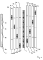
- Fig. 1 shows an example of how an embodiment of an inventive absolute code scale 1 can be constructed or can come about.
- the middle code strip 1 in the right part of the figure is the scale which results according to the invention and is applied as a linear absolute code scale 1 according to the invention by means of a code carrier or directly on a machine component to be measured.
- the four stripes 5a, 5b, 5c, 5d to the left thereof contain the first periodically repeated absolute code 2 whose primary period is represented by the black frames. From right to left, the stripes 5a, 5b, 5c, 5d are respectively in the scale direction along the absolute code Scale, in particular by a fraction of the primary period length of the absolute coding. By way of example, approximately from the center to the left, a phase shift V is shown by 0/64 for stripe 5a, 1/64 for stripe 5b, 3/64 for stripe 5c and 6/64 of the period length for stripe 5d. All Strips 5a, 5b, 5c, 5d have, apart from the displacement, the same absolute code.
- the four right codestrips 6a, 6b, 6c, 6d contain in a manner analogous to the left side a second, from the first different and in particular to this codeword foreign, periodically continued absolute code 3, which also in each of the strips 6a, 6b, 6c, 6d in the direction of the scale is shifted differently.
- the shift can again take place by a fraction of the primary period length of this absolute code.
- approximately from the center to the right is a phase shift V of 0/64 for strip 6a, 1/64 for strip 6b, 3/64 for strip 6c and 6/64 of the period length for strip 6d.
- first and second coding are done alternately, so alternately once from the left and once from the right side. This is clearly visible through the different pitch gradients.
- the parts used are each labeled.
- the respective elements are labeled 2a, 3a, 2b, 3b, 2c, 3c, 2d and 3d.
- the letter index corresponds to the phase shift
- the different pitch slope shown here would not be necessary because these portions are uniquely distinguishable from the code.
- both absolute code sequences can be extracted from a single maximal sequence by using these as in EP 0 268 558 is divided into two parts of different primary period lengths, since the two resulting absolute code sequences are codeword foreign to each other.
- the consequences can be created or evaluated according to the same education law.
- any other Consequences can be used with the required properties of codeword alienation, for example, systematically or empirically developed by suitable software consequences.
- the absolute code scale 1 shown only shows a section of the possible according to the inventive principle, maximum length of the resulting absolute code sequence 1, in which this would start again to repeat and thus ambiguous. With correspondingly a plurality of left and right strips 5n and 6n, the above-described procedure can be continued.
- the above principle can also be extended to more than the two basic absolute code sequences 5 and 6 shown here, for example to three or more basic absolute code sequences, which are then lined up according to the inventive approach alternately and with different phase offsets.
- FIG. 1 an example of an embodiment of an applicable for reading the inventive absolute code scale 1 code reading units 4 is shown, which for example via four separated linear readout areas 8a, 8b, 8c, 8d has, with which arranged on the absolute code scale according to the above scheme code marks be read out, and based on their reading the absolute codes are evaluated.
- a single continuous line sensor such as a CCD line could be applied. Further details will be given elsewhere.
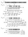
- Fig. 2 clarifies again a possible conclusion of a scale according to the invention and / or explains its evaluation for absolute position determination.
- the left four auxiliary scales 5a, 5b, 5c, 5d each consist of periodically continued primitive absolute codes. Their primary period is characterized by the lateral lines 3, which respectively mark the beginning / end of a period, also marked with the dimension line 9.
- An example of possible values of a usable binary absolute code sequence is given next to the code pattern.
- the code marks formed here by way of example as code lines are inclined by +45 degrees relative to the scale direction for this absolute code.
- the auxiliary auxiliary scale 5d from the left can be considered, for example, as reference for all auxiliary scales 5 on the left side of the absolute code scale 1 according to the invention, which is finally physically fixed to the measurement object and used for the measurement.
- auxiliary scale 5c by 1/64 period length 9 of the moved downwards in the primitive period.
- auxiliary scale 5b at 3/64 and at the left auxiliary scale 5d at 6/64.
- Such a shift can be continued accordingly in more than the four auxiliary scales shown here by way of example, as will be explained in more detail below.
- the shift can be seen in the figure also by the point next to one of the respective code period markers 3, which delimit the primary periods.
- Portions from these auxiliary scales 5a, 5b, 5c, 5d, which are used for the absolute code scale 1 according to the invention, are each marked with a rectangular frame and their use is symbolized by horizontal lines and an arrow.
- every second section of the absolute code scale 1 originates in the middle of one of the auxiliary scales 5a, 5b, 5c, 5d from the left side.
- the four auxiliary scales 6a, 6b, 6c, 6d shown on the right likewise consist of periodically repeated primitive sections, characterized by the lateral bars, which respectively indicate the beginning / end of a period.
- the code bars of the code marks are inclined to the right but by -45 degrees.
- the fourth auxiliary scale 6d from the right can again be regarded as a reference for all auxiliary scales on the right.
- the auxiliary scale 5c is shifted downward by 1/64 period length of the primitive period.
- the evaluation of the inventive absolute code scale 1 is carried out according to a further aspect of the invention such that the absolute position is determined based on the offset between two sections with the same absolute code sequence. Accordingly, the offset is introduced in a defined or known manner. This allows to create an absolute code scale which is longer than the primary period of the absolute codes used. In the readout, a range of the absolute code scale must be detected correspondingly longer than the longer of the first or second section in the absolute code scale 1, plus at least twice the code word length of the absolute code required for the absolute value determination (ie, the greater degree of the first or second code) second absolute code sequence 5 or 6).
- the length of the section of the absolute code sequences 5 and 6, which is used for the inventive absolute code scale 1 also greater than or at least equal to the required absolute value codeword length of the absolute code (ie, for example, the degree of absolute code sequence ) have to be.
- This sufficient number is due to the fact that with this an absolute code sequence must be detectable, based on which the absolute code sequence is uniquely determined, so at least about the length of a unique code word (respectively the degree of absolute code sequence 5 or 6).
- a code word value of the intermediate second absolute code sequence can be evaluated, and an absolute position determination can be made on the basis of the relation of first to second absolute code word read.
- a self-initialization of the measuring system can also take place by moving the code scale with the reading head 4, that is to say in particular without external aids.
- the sequence of sections described above also allows a simple denomination of the inventive absolute code scale 1, in which, for example, prefabricated code scales parts can be strung together during assembly to cover the absolute length to be measured, or the code scales 1 are cut to length as needed can.
- the inventive absolute code scale 1 remains readable and unique.
- the accuracy of the interfaces between the juxtaposed absolute-code scale parts 1 is not highly critical, at best, the invention anyway already large, maximum absolutecodierbare length is reduced by inaccuracies.
- this principle of the present invention can be used, according to which the absolute position consists of a phase offset of respectively two regions or sections of segments from the same first absolute code sequence passing through a region of segments at least one other, second absolute code sequence are separated, even without such an oblique code mark implement, so for example with a uniform pitch, especially with orthogonal to the direction of measurement lines running.
- the principle of the transverse deviation determination shown here in a specific embodiment, in which the transverse deviation is determined from the position of different regions relative to one another, could therefore also be considered as an independent invention per se.
- the area position is - as explained - coded on the difference of the phase positions.
- the regions with the same straight line slope are considered against each other, in the example with two alternately successive parts of two absolute codes each having different orientations of the code marks or code elements, e.g. the regions with even or odd index. Since both considered areas then have the same orientation, a possible lateral shift along the code scale 1 has no effect on the relative position of these two areas to each other.
- phase angle of the absolute code used in a first of the areas relative to the same in a second area with the same but phase-shifted absolute code of the same orientation regardless of the lateral position of the read head 4 can be determined transversely to the scale direction, and from this phase together with the read code the absolute position in the direction of the scale.
- 64 different phases are used by way of example in the variant illustrated here by way of example.
- phase sequence than the linearly increasing phase position in the above example, however, can also be used.
- each of these phase differences may originate from two possible neighboring regions that are 180 degrees out of phase with each other. Since only a small part of the sequence is observed, this uncertainty is easy to assign.
- the first absolute sequence lying, second absolute sequence are used.
- a resulting offset of the two absolute code sequences which results from their different primary period lengths, can be used to evaluate the primary period of the inventive combination of the two absolute code sequences and the thus clearly absolutecodierbare length in a specific embodiment of the invention continue to extend the resulting code pattern.
- such a 180 degree uncertainty can also be avoided if it is accepted that then the maximum code strip length is only one-half or that e.g. is compensated for using a correspondingly longer coding.
- an absolute code may be in the form of a binary maximum sequence of degree 7, eg with the law of formation (x ⁇ 7 + x ⁇ 3 + x ⁇ 2 + x ⁇ 1 + 1), as an example in the first binary code sequence: 10010111110001000000011001101100011100111010111000010011000 00101 ... and in the second binary absolute code sequence: 01011010010010100111100100011010100001111111011101101111010 00101 ... be split.
- the position of these regions can be determined within a period of length 64, with resolution of the 180 degree uncertainty even a period of length 128.
- the cutouts with the same straight line pitch can be designed to have different widths.
- the different period length of the two maximum sequences is compensated.
- the entire, absolutely absolutely codable length is thus significantly more than the length of the two individual absolute codes per se, without the evaluation effort by larger evaluation tables or education laws of higher order, especially if a divided into fragments maximum sequence is used with common educational law.
- a practical embodiment of the coding - as already mentioned - be designed in an advantageous manner such that the code values can be determined with an evaluation of a ratio between two distances and / or widths in code elements - and not in their respective absolute widths and / or distances, with which the code value determination in particular temperature-independent designed.
- the representation of the coding in the form of relative values of code mark position in relation to distances and / or widths of a fixed raster can take place - instead of evaluating the code on the basis of respective absolute values of code mark widths or code mark intervals.
- an evaluation according to this aspect of the invention is more stable and a decision threshold in the value assignment in the context of the detection can be set lower. This allows, for example, instead of a 2-valued coding, the use of a 4-, 8- or any other multi-valued coding.
- this aspect of the present invention pertains to which as a dependent embodiment of the present invention or at best as independent could be considered independent invention - a position coding for a position sensor, in particular an optical absolute position code, formed by an arrangement of a plurality of code elements or code marks on a code carrier which is movable relative to a code reading unit, and with which code reading unit based on a detection of a an absolute position of the reading unit relative to the code carrier can be determined, which is characterized in that an information content of the position coding in a ratio of a first geometric characteristic, in particular a geometric extension of a code element and / or a distance between two code elements, one of the code elements is formed relative to a second geometric characteristic of one of the code elements.
- the ratio can be in particular a relative ratio of a distance between two or more of the code elements to which distance a spatial position of another code element is set in relation.
- a fixed, in particular regular, grid of code elements may be formed, each with arranged between this grid code elements.
- a position of the intermediate code element can be determined, which position is then set in accordance with this aspect of the invention as a counter relative to the distance of the grid as a denominator in proportion, and which ratio then represents that value which is compared to evaluation with one or more decision thresholds to determine a discrete value for the particular code element which then forms a codeword for itself or with discrete values of further code values, which codeword indicates the absolute position or is used for the phase offset determination explained above.
- a plurality of code elements of the grid can accordingly be included, for example by interpolation or least-square-fit of several distances.
- the angle in radians is shown on the abscissa 31 and the pulses corresponding to the above table are marked with crosses 30.
- the decision threshold according to the invention which can be used for code value recognition, distinguishing the code values with the naked eye is difficult.
- the setting of corresponding decision threshold values can accordingly be carried out to determine a discrete code value.
- the read-out values of the code elements in this example are linear positions of the code elements along the reading direction of the sensor of the read head. Such a linear position can be determined, for example, according to a threshold value principle or with a determination of a center or center of gravity in the signal caused by the code element in the reading-out position sensor.
- the principle of the invention shown by way of example can also be applied in an equal manner to codes of other significances, and according to this example, or also according to one of the other alternatives outlined here.
- the significance is, as the number of codable with a code mark number of different code values (also called code word alphabet) of the encoding at least two, preferably greater two, in particular greater 3, greater 7, greater 15 or even greater.
- code word alphabet also called code word alphabet
- two or more different code marks between two raster marks can be evaluated.
- Fig. 5, Fig. 5a, Fig. 5b and Fig. 5c show exemplary embodiments of an inventive absolute code scale 1 as described above, in particular in the form of examples of advantageous in some respects design option, which represent a special aspect of the invention, which with a different than the above-described absolute code scales, possibly even as an independent invention can be seen.
- Shown is a section of a linear absolute-code scale 1 according to the invention, in which exemplary design possibilities of the circled area Fig. 5 in Fig. 5a, 5b, 5c again zoomed out are shown.
- the differences and ratio values 45 evaluated in accordance with this aspect of the invention are associated with decision thresholds corresponding to code values 46 or 47 from which the frame encoded code words can be formed, which then represent the unique absolute information of the absolute code sequence.
- the code marks 19 are formed as lines, which preferably at least are oriented approximately orthogonal to the direction of read along the absolute code scale 1 and the sensor 4.
- the lines may also be aligned as shown elsewhere oblique to the read-out direction, for example in 30 °, 45 ° and / or 60 °, or any angle between them.
- These lines 19 are read, for example, with a line sensor 4 along a substantially contiguous line. Due to the line-shaped scanning, a possible inclination of the lines from the perspective of the sensor 4 (apart from the absolute code mark widths changed by the oblique section of the detection direction with the code marks) is in any case not recognizable.
- An inclination of the code pattern is at most determined by the change in the width of the code marks and / or their distances in the direction of the line of intersection of the sensor readout whose disturbing influence according to this aspect of the invention is just reduced or avoided.
- a change in the width of the code marks for example, can be used, for example, to determine tilting.
- the orientation of the code marks 19 shown with respect to linear code scale direction is therefore not to be seen as limiting.
- an output signal 40 of the sensor 4 is shown, for example a CCD or CMOS line in one embodiment as an optical absolute code scale in the through or reflected-light method.
- This sensor signal 4 is subjected to an evaluation in which the positions of the code marks 19 (and the raster marks 48) with respect to the sensor 4 are determined. For example, a center point, center of gravity, peak value, beginning and end of a threshold value violation, etc., and its position relative to the sensor 4, can be evaluated as an option also in sub-pixel resolution of the sensor to be determined - as this example, in the case of a center point determination in the curve 41 is shown.
- one, or preferably several, of the determined positions of the code marks can be used for a determination of the fine position 44 of the read out absolute code word explained below.
- an averaging or a least-square fit of the detected raster marks 48 known in their position can be used.
- relative ratios are used in the absolute code determination.
- the code mark value 45 then results as a ratio of numerator to denominator Z / N.
- These ratios 45 are compared with decision thresholds and thus discretized into code values 46.
- the coding can thus be evaluated more safely or the decision thresholds can thus be closer together and the code mark 19 can be read out in a multi-valued manner, eg tertiary as shown in the code word 47, or several bits (2, 3 or more) can be coded with a single code mark ,
- fewer code marks 19 are needed to represent the absolute value codeword, and correspondingly fewer fine pitches can be used, which can improve, for example, manufacturing and error resistance.
- the code elements 19 can also be coded on the basis of their width, as in the exemplary embodiment in FIG Fig. 5b is shown.
- the ratio used for evaluation according to this aspect of the invention in such an embodiment can not only have a relative relationship of different distances, but also e.g. be a relative relationship of different widths of different code marks and / or a ratio of width to distance or a ratio of distance to width.
- its width in addition to the position of the code mark 19, its width can also be evaluated as another code word element.
- these widths are visible, which are shown in the sensor signal evaluation 41 in the two components width v and position pos.
- v as the area of a center of gravity evaluation
- pos as the position of the center of gravity.
- the values v and pos can also be used according to other principles, such as a threshold value principle or the like. be determined.
- the code value is again determined as a ratio, in this example as a ratio of position 42a as counter Za to position 43a as denominator Na, giving the ratio 45a of Za / Na as code value.
- a ratio of the width 42b as the counter Zb to a width 43b is taken as the denominator Nb, which gives the ratio 45b of Zb / Nb as the code value.
- Both the distance ratio 45a and the width ratio 45b can be combined into a single code value for the code mark 19, whereby the code alphabet is expanded, in particular if one or both ratios are evaluated in a multi-valued way. Illustrated by way of example is a three-valued encoding of the position ratio 45a and a bivalent encoding of the width ratio 45b, this being not restrictive and other, in particular higher-order, coding for one or both of the ratios 45a and 45b being applicable in an analogous manner.
- the code alphabet of a code mark in the absolute value codeword 47 then includes, for example, ⁇ a, b, c, d, e, f ⁇ for an exemplary word length of the absolute code of four.
- a single code mark 19 in this example of an embodiment thus encodes two values - a first value of its position pos, preferably relative to a metrologically determined grid spacing or to another code mark element - and also a second value of its width v, preferably with respect to a width the raster marks or another code mark element.
- the scope of the codeword alphabet thus results from the number of differentiated, in particular relative, positions multiplied by the number of differentiated, in particular relative, widths.
- each code mark is a two-dimensional code value with (center of gravity position, volume), which is represented geometrically one-dimensionally and can be determined with a one-dimensional line sensor, but is two-dimensional in the value range.
- Fig. 5c the coding is represented by different distances 42 as counter Z of equal width lines 43 as denominator N.
- the code value determined from the ratio Z / N - ie from the ratio of line pitch to line width - is evaluated in this example as a more than two-valued code alphabet, from which an absolute code codeword 45 is composed, in particular an absolute code scale 1 according to the invention described above.
- This absolute code codeword 45 can directly encode an absolute position value.
- the offset between two determined, separate absolute code codewords 45 from the same absolute code sequence in particular the phase offset with respect to the primary period of the absolute code
- can also be used to encode the absolute position, as described in another aspect of US Pat invention described here has already been explained.
- the absolute value of the position determined thereby can be determined as coarse position on the basis of an evaluation of one or more codeword values 47 of several code marks 19, in particular in the grid 48.
- the absolute position determination can also be determined as explained from the offset of two sections of the same absolute code.
- a fine position can be determined based on the position of the grid 48 and / or the code value-carrying code marks 19, which is determined relative to the sensor element 4.
- this can be done with CG positions of the code elements 19, especially when taking into account the center of gravity positions a plurality of code marks 19 and / or grid marks 48, specifically with an interpolation or a least-square fit of the center of gravity positions and / or code mark widths, an exact position of the read head 4 relative to the position code 1 on the code carrier are determined.
- Fig. 6 again shows a sketch of a section of an absolute code scale 1 according to the invention, in an embodiment with which transverse offsets ⁇ y can also be determined.
- An offset axis 10b is shown about the transverse deviation ⁇ y, at least approximately orthogonal to the longitudinal axis of the linear absolute code scale.
- Such an approximation of an at least approximately orthogonal transverse offset is sufficient in most cases, as a possible angular misalignment of the axes 10a and 10b smaller and mostly negligible due to the dimensional relationships.
- the alternating sections of the first absolute codes 5a, 5b, 5c and the second absolute codes 6a, 6b are clearly recognizable and distinguishable at their code mark alignment, but are also explicitly labeled again with CODE5 and CODE6.
- the orientations from the sensor's point of view can not be determined per se, since the sensor 4 detects only the intersection areas of the code marks 19 with the sensor 4, as shown in detail in FIG Fig. 6 is clarified.
- the read area of the code reader 4 shown here throughout it can also be interrupted into a plurality of pieces sufficiently long to detect the absolute code value, which pieces can be arranged in particular in a harmonious manner for dividing the sections.
- the code values of the codes 5 and 6 and the position of the codes 5 and 6 are determined along the sensor.
- the distinction between codings 5 or 6 is based on an assignment of the read code words to the respective absolute codes, which are indeed codewordfeld.
- the absolute positions are determined on the basis of the offset 16 between code values from two sections of the same absolute code, thus for example the offset 16 between section 6a and 6b, the offset between 5a and 5b or between 5b and 5c.
- a greater distance such as an offset between 5a and 5c, or multiple offsets could also be considered.
- the transverse offset ⁇ y can thus be quantified.
- the value of the code word CODE5 and / or CODE6 read out can also be used in the evaluation.
- the points of intersection of the code marks 19 with the read axis 10 of the read head 4 are marked with points which are evaluated at least in their geometric position relative to the read head 4.
- the value of the coding can be determined, for example, on the basis of the marked distances between the code marks, or another known, in particular one of the methods listed here.
- an absolute position information is determined whose fine position is related to the position of one or more code marks determine the sensor 4 in particular to sub-pixel accuracy of the sensor 4.
- Fig. 8 Shows an example of a simplified block diagram of the invention.
- the absolute code scale is read with at least one linear sensor aligned at least approximately along the scale.
- the positions of the code marks of the absolute code scale are determined. At best, further code-value-forming features of the code marks can also be evaluated. In particular, the above-described expansion-independent coding and the corresponding determination of the code words can be used.
- Determining the code words based on a relative relationship between geometric code mark features is shown in block 73.
- the codewords are assigned to a first or second absolute code sequence on the basis of the codeword values and a determination of the geometric position of the codewords with respect to the sensor.
- a geometric offset between two codewords is determined from the same absolute code sequence, and from this an absolute position is determined based on this offset.
- Fig. 9 is an example of an embodiment with at least one inventive code scale 1x, 1x ', 1y, 1z shown in the form of an example sketched coordinate measuring machine 60 in gantry design.
- at least one of the code scales shown 1x, 1x ', 1y, 1z which are indirectly applied via a code carrier or directly to fixed or movable components 21, 20, 25, 26, 27 of the machine, is designed according to the invention.
- the spatial position of the measuring head 27 is determined, based on which a workpiece, not shown here, is measured in the direction of the space coordinates Fx, Fy, Fz, Rq shown by way of example.
- any misalignments can be detected and / or numerically or mechanically compensated.
- the inventive code scale be designed such that the readout of the code takes place even with any temperature expansions of the code scale error-free.
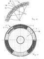
- absolute code scales according to the invention and their special embodiments can also be used in a non-linear arrangement in an analogous manner optionally in non-strictly linear position sensors, for example also in angle encoders. Exemplary examples are in 10 and FIG. 11 shown.
- Such a widely used, special embodiment can be formed, for example, in the above description, the term “linear” is replaced by "angle” and the code scale is closed in such a way that even at the interface From the beginning and end of two different absolute code sequences or absolute code parts abut each other - ie the absolute code sequences are arranged alternately over the entire evaluated peripheral range of the encoder.
- a code carrier 80 which carries the absolute code scale according to the invention in an annular segment-shaped arrangement, may be designed such that different sections of a first absolute code sequence 5 and a second absolute code sequence 6 each alternately line up in (for example, at least approximately equal) angular segments along the circumference.
- One or more reading heads 4a, 4b are each formed with a plurality of sensor elements for detecting the physical features of the code marks 19 to be evaluated, which are arranged such that the transition points from the first absolute code sequence 5 to the second absolute code sequence 6 can be detected with them, so that the inventive displacement of two sub-sections from the same absolute code sequences can be detected to each other.
- this displacement codes an absolute position information, in particular in an analogous manner, as already explained above with reference to a linear coding has been.
- the code sequences can be assigned to one of the absolute code sequences based on the unique affiliation of these code values.
- the code detection can take place with an arrangement of sensor elements along a circular arc.
- a linear arrangement of sensor elements as in the detection area 4a.
- either a straight chord piece of the crooked code progression can take place.
- any distortion due to the different course or an oblique section of the code marks can be at least partially compensated, so that a sufficiently robust code value recognition of monovalent or multivalued codes is achieved.
- an image or projection of a curved circular ring segment of the code scale onto a linear sensor can take place alternately or additionally also by means of optical components, so that the curvature is at least partially compensated.
- the code values are contained in the form of relative relationships of the geometric design of the code marks, it is particularly advantageous, since in this case also a detection of the curved code scale with a straight, linear sensor element, by respectively local evaluation of the relative references the detected characteristics of the code marks, even the caused by the different curvatures of code and detection element distortion of the detected code marks does not affect the code value determination.
- the aspect already described above of the orientation of the respective code marks which is different for each of the absolute code sequences, can also be implemented, and thus, for example, a lateral offset, tumbling, eccentricity, or other misalignments can be detected and / or quantified, as already described with reference to a liner cursor the counterpart of a lateral offset and / or a height offset has been described.
- an absolute code scale 1 of a rotary encoder which is composed of a first absolute code sequence 5 having a first primary code period length which is periodically continued, and at least one second absolute code sequence 6 having a second primary code period length which is periodically continued ,
- the first and the at least second absolute code sequences 5 and 6 are mutually foreign to code words.
- a section 2 from the first absolute code sequence 5 and a section 3 from the at least second absolute code sequence 6 are arranged alternately one behind the other, wherein in the different sections 2/3 from the same absolute code sequence 5/6 along this arrangement, the Absolutcode sequences 5/6 are mutually shifted.
- the absolute code sequences in the sections from the same sequences are phase-shifted by a respective different fraction of the primary period length of the absolute code sequence 5/6.
Landscapes
- Physics & Mathematics (AREA)
- General Physics & Mathematics (AREA)
- Transmission And Conversion Of Sensor Element Output (AREA)
Priority Applications (3)
| Application Number | Priority Date | Filing Date | Title |
|---|---|---|---|
| EP15178188.7A EP3121565B1 (fr) | 2015-07-24 | 2015-07-24 | Determination de position absolue |
| CN201610584596.3A CN106370213B (zh) | 2015-07-24 | 2016-07-22 | 绝对位置确定 |
| US15/217,570 US10082409B2 (en) | 2015-07-24 | 2016-07-22 | Absolute position determination |
Applications Claiming Priority (1)
| Application Number | Priority Date | Filing Date | Title |
|---|---|---|---|
| EP15178188.7A EP3121565B1 (fr) | 2015-07-24 | 2015-07-24 | Determination de position absolue |
Publications (2)
| Publication Number | Publication Date |
|---|---|
| EP3121565A1 true EP3121565A1 (fr) | 2017-01-25 |
| EP3121565B1 EP3121565B1 (fr) | 2018-09-12 |
Family
ID=53758072
Family Applications (1)
| Application Number | Title | Priority Date | Filing Date |
|---|---|---|---|
| EP15178188.7A Active EP3121565B1 (fr) | 2015-07-24 | 2015-07-24 | Determination de position absolue |
Country Status (3)
| Country | Link |
|---|---|
| US (1) | US10082409B2 (fr) |
| EP (1) | EP3121565B1 (fr) |
| CN (1) | CN106370213B (fr) |
Families Citing this family (13)
| Publication number | Priority date | Publication date | Assignee | Title |
|---|---|---|---|---|
| DE102018200449A1 (de) | 2018-01-12 | 2019-07-18 | Dr. Johannes Heidenhain Gmbh | Positionsmesseinrichtung |
| US10914612B2 (en) | 2018-01-29 | 2021-02-09 | Faro Technologies, Inc. | Indexed optical encoder |
| JP7096009B2 (ja) * | 2018-02-21 | 2022-07-05 | 株式会社ミツトヨ | 位置検出エンコーダ及び位置検出エンコーダの製造方法 |
| WO2019224400A1 (fr) * | 2018-05-25 | 2019-11-28 | Sensitec Gmbh | Codeur absolu |
| US10502593B1 (en) * | 2018-06-07 | 2019-12-10 | Philip M. Johnson | Linear and rotary multitrack absolute position encoder and methods using the same |
| US11237024B2 (en) * | 2018-10-08 | 2022-02-01 | Pixart Imaging Inc. | Optical encoder with covered photo diode |
| US11221238B2 (en) | 2019-07-05 | 2022-01-11 | Canon Kabushiki Kaisha | Optical encoder and drive control device comprising a light receiving element to receive a first interference fringe formed by a first periodic pattern and a second diffracted light from a second periodic pattern toward the first periodic pattern |
| EP3789735B1 (fr) | 2019-09-04 | 2021-11-10 | Dr. Johannes Heidenhain GmbH | Dispositif de mesure de position |
| CN111238404B (zh) * | 2020-02-26 | 2021-04-20 | 江苏集萃华科智能装备科技有限公司 | 一种二值码相移周期码错位的校正方法 |
| JP7443140B2 (ja) * | 2020-04-09 | 2024-03-05 | Dmg森精機株式会社 | 位置検出装置 |
| WO2022070132A1 (fr) * | 2020-10-02 | 2022-04-07 | TESA Sàrl | Codeur de position absolue pour instrument de mesure |
| US12085382B2 (en) * | 2021-02-17 | 2024-09-10 | Novanta Corporation | Rotary position encoding using non-maximal-length pseudo-random codes |
| CN113551578B (zh) * | 2021-08-01 | 2023-07-07 | 李里 | 条形位移码、条形位移码尺和位移检测装置 |
Citations (9)
| Publication number | Priority date | Publication date | Assignee | Title |
|---|---|---|---|---|
| EP0042179A2 (fr) | 1980-06-17 | 1981-12-23 | Tokyo Kogaku Kikai Kabushiki Kaisha | Codeur |
| DE3703327A1 (de) * | 1986-02-18 | 1987-08-20 | Mettler Instrumente Ag | Verfahren und einrichtung zur optischen positionsmessung |
| EP0268558A2 (fr) | 1986-11-19 | 1988-05-25 | Leica AG | Appareil pour la mesure de longueurs ou d'angles |
| DE3818044A1 (de) | 1988-05-27 | 1989-11-30 | Christoph Dipl Phys Kuehne | Praezisions-messeinrichtung fuer grosse verschiebungen |
| DE68920123T2 (de) * | 1988-11-08 | 1995-05-04 | Heidenhain Gmbh Dr Johannes | Dekodierung von Zufallssequenzen. |
| DE19732398A1 (de) | 1997-07-28 | 1999-02-04 | Joerg Fricke | Vorrichtung und Verfahren zur absoluten Messung der Position auf einer Ebene und des Drehwinkels um die Achse senkrecht zu dieser Ebene (x-y-phi-Messung) |
| EP1043571A1 (fr) * | 1999-04-10 | 2000-10-11 | TR Electronic GmbH | Dispositif de mesure de la position absolue |
| DE102008054042A1 (de) * | 2008-10-30 | 2010-05-06 | Dr. Johannes Heidenhain Gmbh | Absolute Positionscodierung und Positionsmessvorrichtung |
| CH704584A2 (de) | 2011-03-02 | 2012-09-14 | Hexagon Technology Ct Gmbh | Herstellungsverfahren für einen Codeträger mit einer absolutcodierten Codespur mit einer optimierten Anzahl von Teilungen. |
Family Cites Families (4)
| Publication number | Priority date | Publication date | Assignee | Title |
|---|---|---|---|---|
| DE102008022027A1 (de) | 2008-05-02 | 2009-11-05 | Dr. Johannes Heidenhain Gmbh | Positionsmesseinrichtung |
| DE102008053985A1 (de) * | 2008-10-30 | 2010-05-06 | Dr. Johannes Heidenhain Gmbh | Absolute Winkelcodierung und Winkelmessvorrichtung |
| CN101476902B (zh) | 2009-01-13 | 2010-09-22 | 常州大地测绘科技有限公司 | 单码道绝对位置编码方法 |
| EP3064902B1 (fr) | 2015-03-06 | 2017-11-01 | Hexagon Technology Center GmbH | Système de détermination de positions |
-
2015
- 2015-07-24 EP EP15178188.7A patent/EP3121565B1/fr active Active
-
2016
- 2016-07-22 CN CN201610584596.3A patent/CN106370213B/zh active Active
- 2016-07-22 US US15/217,570 patent/US10082409B2/en active Active
Patent Citations (9)
| Publication number | Priority date | Publication date | Assignee | Title |
|---|---|---|---|---|
| EP0042179A2 (fr) | 1980-06-17 | 1981-12-23 | Tokyo Kogaku Kikai Kabushiki Kaisha | Codeur |
| DE3703327A1 (de) * | 1986-02-18 | 1987-08-20 | Mettler Instrumente Ag | Verfahren und einrichtung zur optischen positionsmessung |
| EP0268558A2 (fr) | 1986-11-19 | 1988-05-25 | Leica AG | Appareil pour la mesure de longueurs ou d'angles |
| DE3818044A1 (de) | 1988-05-27 | 1989-11-30 | Christoph Dipl Phys Kuehne | Praezisions-messeinrichtung fuer grosse verschiebungen |
| DE68920123T2 (de) * | 1988-11-08 | 1995-05-04 | Heidenhain Gmbh Dr Johannes | Dekodierung von Zufallssequenzen. |
| DE19732398A1 (de) | 1997-07-28 | 1999-02-04 | Joerg Fricke | Vorrichtung und Verfahren zur absoluten Messung der Position auf einer Ebene und des Drehwinkels um die Achse senkrecht zu dieser Ebene (x-y-phi-Messung) |
| EP1043571A1 (fr) * | 1999-04-10 | 2000-10-11 | TR Electronic GmbH | Dispositif de mesure de la position absolue |
| DE102008054042A1 (de) * | 2008-10-30 | 2010-05-06 | Dr. Johannes Heidenhain Gmbh | Absolute Positionscodierung und Positionsmessvorrichtung |
| CH704584A2 (de) | 2011-03-02 | 2012-09-14 | Hexagon Technology Ct Gmbh | Herstellungsverfahren für einen Codeträger mit einer absolutcodierten Codespur mit einer optimierten Anzahl von Teilungen. |
Also Published As
| Publication number | Publication date |
|---|---|
| CN106370213A (zh) | 2017-02-01 |
| US20170023383A1 (en) | 2017-01-26 |
| US10082409B2 (en) | 2018-09-25 |
| CN106370213B (zh) | 2018-12-18 |
| EP3121565B1 (fr) | 2018-09-12 |
Similar Documents
| Publication | Publication Date | Title |
|---|---|---|
| EP3121565B1 (fr) | Determination de position absolue | |
| DE10296644B4 (de) | Absolute Positionsmessung | |
| DE69113415T2 (de) | Positionskodierer für Linear- oder Winkelmessapparat. | |
| AT509101B1 (de) | Induktive messeinrichtung für längen- und winkelerfassung | |
| EP3064902B1 (fr) | Système de détermination de positions | |
| EP3139132B1 (fr) | Codage absolu de surfaces | |
| EP3511680B1 (fr) | Dispositif de mesure de position | |
| EP0268558A2 (fr) | Appareil pour la mesure de longueurs ou d'angles | |
| EP2342540B1 (fr) | Codage d'angle absolu et dispositif de mesure d'angle | |
| EP2340417B1 (fr) | Dispositif de mesure de position absolue | |
| EP3803278B1 (fr) | Codeur absolu | |
| EP3179216A1 (fr) | Système de mesure de longueur absolu et son procédé de fonctionnement | |
| EP1557646A1 (fr) | Détecteur d'angle de rotation et procédé de balayage optique d'une disque de code d'un détecteur d'angle de rotation | |
| DE102021102053B4 (de) | Bestimmung einer Position | |
| EP2342539B1 (fr) | Dispositif de mesure de position absolue | |
| DE102018118477A1 (de) | Absolutwertgeber | |
| EP1321743A1 (fr) | Système pour mesurer une longueur comprenant une barre de mesure qui se déplace relativement par rapport à des sondes de longueurs mutuellement espacées | |
| DE102006010161B4 (de) | Codestruktur für eine Positionsmesseinrichtung und Positionsmesseinrichtung mit einer solchen Codestruktur | |
| EP4370875B1 (fr) | Système de codage de position et procédé de détermination de la position de la tête de lecture dans un système de codage de position | |
| EP2340418B1 (fr) | Code d'une position absolu et dispositif de mesure de positions | |
| EP3924696B1 (fr) | Dispositif de mesure de position pour mesurer une position absolue | |
| DE102014212268A1 (de) | Positionsmesseinrichtung | |
| EP3789735B1 (fr) | Dispositif de mesure de position | |
| DE102023134625B3 (de) | Vorrichtung und verfahren zur positions-, längen- oder winkelbestimmung sowie verfahren zur bildung einer entsprechenden codierung | |
| EP2870431B1 (fr) | Procédé de détection d'un codage absolu d'une piste de code optique |
Legal Events
| Date | Code | Title | Description |
|---|---|---|---|
| PUAI | Public reference made under article 153(3) epc to a published international application that has entered the european phase |
Free format text: ORIGINAL CODE: 0009012 |
|
| STAA | Information on the status of an ep patent application or granted ep patent |
Free format text: STATUS: THE APPLICATION HAS BEEN PUBLISHED |
|
| AK | Designated contracting states |
Kind code of ref document: A1 Designated state(s): AL AT BE BG CH CY CZ DE DK EE ES FI FR GB GR HR HU IE IS IT LI LT LU LV MC MK MT NL NO PL PT RO RS SE SI SK SM TR |
|
| AX | Request for extension of the european patent |
Extension state: BA ME |
|
| STAA | Information on the status of an ep patent application or granted ep patent |
Free format text: STATUS: REQUEST FOR EXAMINATION WAS MADE |
|
| 17P | Request for examination filed |
Effective date: 20170717 |
|
| RBV | Designated contracting states (corrected) |
Designated state(s): AL AT BE BG CH CY CZ DE DK EE ES FI FR GB GR HR HU IE IS IT LI LT LU LV MC MK MT NL NO PL PT RO RS SE SI SK SM TR |
|
| GRAP | Despatch of communication of intention to grant a patent |
Free format text: ORIGINAL CODE: EPIDOSNIGR1 |
|
| STAA | Information on the status of an ep patent application or granted ep patent |
Free format text: STATUS: GRANT OF PATENT IS INTENDED |
|
| INTG | Intention to grant announced |
Effective date: 20180424 |
|
| GRAS | Grant fee paid |
Free format text: ORIGINAL CODE: EPIDOSNIGR3 |
|
| GRAA | (expected) grant |
Free format text: ORIGINAL CODE: 0009210 |
|
| STAA | Information on the status of an ep patent application or granted ep patent |
Free format text: STATUS: THE PATENT HAS BEEN GRANTED |
|
| AK | Designated contracting states |
Kind code of ref document: B1 Designated state(s): AL AT BE BG CH CY CZ DE DK EE ES FI FR GB GR HR HU IE IS IT LI LT LU LV MC MK MT NL NO PL PT RO RS SE SI SK SM TR |
|
| REG | Reference to a national code |
Ref country code: GB Ref legal event code: FG4D Free format text: NOT ENGLISH |
|
| REG | Reference to a national code |
Ref country code: CH Ref legal event code: EP |
|
| REG | Reference to a national code |
Ref country code: CH Ref legal event code: NV Representative=s name: KAMINSKI HARMANN PATENTANWAELTE AG, LI |
|
| REG | Reference to a national code |
Ref country code: IE Ref legal event code: FG4D Free format text: LANGUAGE OF EP DOCUMENT: GERMAN |
|
| REG | Reference to a national code |
Ref country code: DE Ref legal event code: R096 Ref document number: 502015005811 Country of ref document: DE |
|
| REG | Reference to a national code |
Ref country code: AT Ref legal event code: REF Ref document number: 1041153 Country of ref document: AT Kind code of ref document: T Effective date: 20181015 |
|
| REG | Reference to a national code |
Ref country code: NL Ref legal event code: FP |
|
| REG | Reference to a national code |
Ref country code: LT Ref legal event code: MG4D |
|
| PG25 | Lapsed in a contracting state [announced via postgrant information from national office to epo] |
Ref country code: FI Free format text: LAPSE BECAUSE OF FAILURE TO SUBMIT A TRANSLATION OF THE DESCRIPTION OR TO PAY THE FEE WITHIN THE PRESCRIBED TIME-LIMIT Effective date: 20180912 Ref country code: RS Free format text: LAPSE BECAUSE OF FAILURE TO SUBMIT A TRANSLATION OF THE DESCRIPTION OR TO PAY THE FEE WITHIN THE PRESCRIBED TIME-LIMIT Effective date: 20180912 Ref country code: GR Free format text: LAPSE BECAUSE OF FAILURE TO SUBMIT A TRANSLATION OF THE DESCRIPTION OR TO PAY THE FEE WITHIN THE PRESCRIBED TIME-LIMIT Effective date: 20181213 Ref country code: NO Free format text: LAPSE BECAUSE OF FAILURE TO SUBMIT A TRANSLATION OF THE DESCRIPTION OR TO PAY THE FEE WITHIN THE PRESCRIBED TIME-LIMIT Effective date: 20181212 Ref country code: BG Free format text: LAPSE BECAUSE OF FAILURE TO SUBMIT A TRANSLATION OF THE DESCRIPTION OR TO PAY THE FEE WITHIN THE PRESCRIBED TIME-LIMIT Effective date: 20181212 Ref country code: SE Free format text: LAPSE BECAUSE OF FAILURE TO SUBMIT A TRANSLATION OF THE DESCRIPTION OR TO PAY THE FEE WITHIN THE PRESCRIBED TIME-LIMIT Effective date: 20180912 Ref country code: LT Free format text: LAPSE BECAUSE OF FAILURE TO SUBMIT A TRANSLATION OF THE DESCRIPTION OR TO PAY THE FEE WITHIN THE PRESCRIBED TIME-LIMIT Effective date: 20180912 |
|
| PG25 | Lapsed in a contracting state [announced via postgrant information from national office to epo] |
Ref country code: HR Free format text: LAPSE BECAUSE OF FAILURE TO SUBMIT A TRANSLATION OF THE DESCRIPTION OR TO PAY THE FEE WITHIN THE PRESCRIBED TIME-LIMIT Effective date: 20180912 Ref country code: LV Free format text: LAPSE BECAUSE OF FAILURE TO SUBMIT A TRANSLATION OF THE DESCRIPTION OR TO PAY THE FEE WITHIN THE PRESCRIBED TIME-LIMIT Effective date: 20180912 Ref country code: AL Free format text: LAPSE BECAUSE OF FAILURE TO SUBMIT A TRANSLATION OF THE DESCRIPTION OR TO PAY THE FEE WITHIN THE PRESCRIBED TIME-LIMIT Effective date: 20180912 |
|
| PG25 | Lapsed in a contracting state [announced via postgrant information from national office to epo] |
Ref country code: ES Free format text: LAPSE BECAUSE OF FAILURE TO SUBMIT A TRANSLATION OF THE DESCRIPTION OR TO PAY THE FEE WITHIN THE PRESCRIBED TIME-LIMIT Effective date: 20180912 Ref country code: CZ Free format text: LAPSE BECAUSE OF FAILURE TO SUBMIT A TRANSLATION OF THE DESCRIPTION OR TO PAY THE FEE WITHIN THE PRESCRIBED TIME-LIMIT Effective date: 20180912 Ref country code: PL Free format text: LAPSE BECAUSE OF FAILURE TO SUBMIT A TRANSLATION OF THE DESCRIPTION OR TO PAY THE FEE WITHIN THE PRESCRIBED TIME-LIMIT Effective date: 20180912 Ref country code: IS Free format text: LAPSE BECAUSE OF FAILURE TO SUBMIT A TRANSLATION OF THE DESCRIPTION OR TO PAY THE FEE WITHIN THE PRESCRIBED TIME-LIMIT Effective date: 20190112 Ref country code: RO Free format text: LAPSE BECAUSE OF FAILURE TO SUBMIT A TRANSLATION OF THE DESCRIPTION OR TO PAY THE FEE WITHIN THE PRESCRIBED TIME-LIMIT Effective date: 20180912 Ref country code: EE Free format text: LAPSE BECAUSE OF FAILURE TO SUBMIT A TRANSLATION OF THE DESCRIPTION OR TO PAY THE FEE WITHIN THE PRESCRIBED TIME-LIMIT Effective date: 20180912 Ref country code: IT Free format text: LAPSE BECAUSE OF FAILURE TO SUBMIT A TRANSLATION OF THE DESCRIPTION OR TO PAY THE FEE WITHIN THE PRESCRIBED TIME-LIMIT Effective date: 20180912 |
|
| PG25 | Lapsed in a contracting state [announced via postgrant information from national office to epo] |
Ref country code: SM Free format text: LAPSE BECAUSE OF FAILURE TO SUBMIT A TRANSLATION OF THE DESCRIPTION OR TO PAY THE FEE WITHIN THE PRESCRIBED TIME-LIMIT Effective date: 20180912 Ref country code: SK Free format text: LAPSE BECAUSE OF FAILURE TO SUBMIT A TRANSLATION OF THE DESCRIPTION OR TO PAY THE FEE WITHIN THE PRESCRIBED TIME-LIMIT Effective date: 20180912 Ref country code: PT Free format text: LAPSE BECAUSE OF FAILURE TO SUBMIT A TRANSLATION OF THE DESCRIPTION OR TO PAY THE FEE WITHIN THE PRESCRIBED TIME-LIMIT Effective date: 20190112 |
|
| REG | Reference to a national code |
Ref country code: DE Ref legal event code: R097 Ref document number: 502015005811 Country of ref document: DE |
|
| PLBE | No opposition filed within time limit |
Free format text: ORIGINAL CODE: 0009261 |
|
| STAA | Information on the status of an ep patent application or granted ep patent |
Free format text: STATUS: NO OPPOSITION FILED WITHIN TIME LIMIT |
|
| PG25 | Lapsed in a contracting state [announced via postgrant information from national office to epo] |
Ref country code: DK Free format text: LAPSE BECAUSE OF FAILURE TO SUBMIT A TRANSLATION OF THE DESCRIPTION OR TO PAY THE FEE WITHIN THE PRESCRIBED TIME-LIMIT Effective date: 20180912 |
|
| 26N | No opposition filed |
Effective date: 20190613 |
|
| PG25 | Lapsed in a contracting state [announced via postgrant information from national office to epo] |
Ref country code: SI Free format text: LAPSE BECAUSE OF FAILURE TO SUBMIT A TRANSLATION OF THE DESCRIPTION OR TO PAY THE FEE WITHIN THE PRESCRIBED TIME-LIMIT Effective date: 20180912 |
|
| PGFP | Annual fee paid to national office [announced via postgrant information from national office to epo] |
Ref country code: NL Payment date: 20190719 Year of fee payment: 5 |
|
| PGFP | Annual fee paid to national office [announced via postgrant information from national office to epo] |
Ref country code: GB Payment date: 20190719 Year of fee payment: 5 |
|
| PGFP | Annual fee paid to national office [announced via postgrant information from national office to epo] |
Ref country code: CH Payment date: 20190719 Year of fee payment: 5 |
|
| PG25 | Lapsed in a contracting state [announced via postgrant information from national office to epo] |
Ref country code: MC Free format text: LAPSE BECAUSE OF FAILURE TO SUBMIT A TRANSLATION OF THE DESCRIPTION OR TO PAY THE FEE WITHIN THE PRESCRIBED TIME-LIMIT Effective date: 20180912 |
|
| PG25 | Lapsed in a contracting state [announced via postgrant information from national office to epo] |
Ref country code: TR Free format text: LAPSE BECAUSE OF FAILURE TO SUBMIT A TRANSLATION OF THE DESCRIPTION OR TO PAY THE FEE WITHIN THE PRESCRIBED TIME-LIMIT Effective date: 20180912 |
|
| REG | Reference to a national code |
Ref country code: BE Ref legal event code: MM Effective date: 20190731 |
|
| PG25 | Lapsed in a contracting state [announced via postgrant information from national office to epo] |
Ref country code: BE Free format text: LAPSE BECAUSE OF NON-PAYMENT OF DUE FEES Effective date: 20190731 Ref country code: LU Free format text: LAPSE BECAUSE OF NON-PAYMENT OF DUE FEES Effective date: 20190724 |
|
| PG25 | Lapsed in a contracting state [announced via postgrant information from national office to epo] |
Ref country code: IE Free format text: LAPSE BECAUSE OF NON-PAYMENT OF DUE FEES Effective date: 20190724 |
|
| REG | Reference to a national code |
Ref country code: CH Ref legal event code: PL |
|
| REG | Reference to a national code |
Ref country code: NL Ref legal event code: MM Effective date: 20200801 |
|
| GBPC | Gb: european patent ceased through non-payment of renewal fee |
Effective date: 20200724 |
|
| PG25 | Lapsed in a contracting state [announced via postgrant information from national office to epo] |
Ref country code: LI Free format text: LAPSE BECAUSE OF NON-PAYMENT OF DUE FEES Effective date: 20200731 Ref country code: NL Free format text: LAPSE BECAUSE OF NON-PAYMENT OF DUE FEES Effective date: 20200801 Ref country code: CH Free format text: LAPSE BECAUSE OF NON-PAYMENT OF DUE FEES Effective date: 20200731 Ref country code: GB Free format text: LAPSE BECAUSE OF NON-PAYMENT OF DUE FEES Effective date: 20200724 |
|
| PG25 | Lapsed in a contracting state [announced via postgrant information from national office to epo] |
Ref country code: CY Free format text: LAPSE BECAUSE OF FAILURE TO SUBMIT A TRANSLATION OF THE DESCRIPTION OR TO PAY THE FEE WITHIN THE PRESCRIBED TIME-LIMIT Effective date: 20180912 |
|
| PG25 | Lapsed in a contracting state [announced via postgrant information from national office to epo] |
Ref country code: HU Free format text: LAPSE BECAUSE OF FAILURE TO SUBMIT A TRANSLATION OF THE DESCRIPTION OR TO PAY THE FEE WITHIN THE PRESCRIBED TIME-LIMIT; INVALID AB INITIO Effective date: 20150724 Ref country code: MT Free format text: LAPSE BECAUSE OF FAILURE TO SUBMIT A TRANSLATION OF THE DESCRIPTION OR TO PAY THE FEE WITHIN THE PRESCRIBED TIME-LIMIT Effective date: 20180912 |
|
| REG | Reference to a national code |
Ref country code: AT Ref legal event code: MM01 Ref document number: 1041153 Country of ref document: AT Kind code of ref document: T Effective date: 20200724 |
|
| PG25 | Lapsed in a contracting state [announced via postgrant information from national office to epo] |
Ref country code: AT Free format text: LAPSE BECAUSE OF NON-PAYMENT OF DUE FEES Effective date: 20200724 |
|
| PG25 | Lapsed in a contracting state [announced via postgrant information from national office to epo] |
Ref country code: MK Free format text: LAPSE BECAUSE OF FAILURE TO SUBMIT A TRANSLATION OF THE DESCRIPTION OR TO PAY THE FEE WITHIN THE PRESCRIBED TIME-LIMIT Effective date: 20180912 |
|
| PGFP | Annual fee paid to national office [announced via postgrant information from national office to epo] |
Ref country code: DE Payment date: 20250722 Year of fee payment: 11 |
|
| PGFP | Annual fee paid to national office [announced via postgrant information from national office to epo] |
Ref country code: FR Payment date: 20250725 Year of fee payment: 11 |
|
| REG | Reference to a national code |
Ref country code: DE Ref legal event code: R081 Ref document number: 502015005811 Country of ref document: DE Owner name: HEXAGON INNOVATION HUB GMBH, CH Free format text: FORMER OWNER: HEXAGON TECHNOLOGY CENTER GMBH, HEERBRUGG, CH |