EP3121908A1 - Connecteur à fiche - Google Patents
Connecteur à fiche Download PDFInfo
- Publication number
- EP3121908A1 EP3121908A1 EP16176242.2A EP16176242A EP3121908A1 EP 3121908 A1 EP3121908 A1 EP 3121908A1 EP 16176242 A EP16176242 A EP 16176242A EP 3121908 A1 EP3121908 A1 EP 3121908A1
- Authority
- EP
- European Patent Office
- Prior art keywords
- contact
- connector
- opening
- closure element
- diameter
- Prior art date
- Legal status (The legal status is an assumption and is not a legal conclusion. Google has not performed a legal analysis and makes no representation as to the accuracy of the status listed.)
- Granted
Links
Images

Classifications
-
- H—ELECTRICITY
- H01—ELECTRIC ELEMENTS
- H01R—ELECTRICALLY-CONDUCTIVE CONNECTIONS; STRUCTURAL ASSOCIATIONS OF A PLURALITY OF MUTUALLY-INSULATED ELECTRICAL CONNECTING ELEMENTS; COUPLING DEVICES; CURRENT COLLECTORS
- H01R13/00—Details of coupling devices of the kinds covered by groups H01R12/70 or H01R24/00 - H01R33/00
- H01R13/46—Bases; Cases
- H01R13/52—Dustproof, splashproof, drip-proof, waterproof, or flameproof cases
- H01R13/5213—Covers
-
- H—ELECTRICITY
- H01—ELECTRIC ELEMENTS
- H01R—ELECTRICALLY-CONDUCTIVE CONNECTIONS; STRUCTURAL ASSOCIATIONS OF A PLURALITY OF MUTUALLY-INSULATED ELECTRICAL CONNECTING ELEMENTS; COUPLING DEVICES; CURRENT COLLECTORS
- H01R13/00—Details of coupling devices of the kinds covered by groups H01R12/70 or H01R24/00 - H01R33/00
- H01R13/02—Contact members
- H01R13/10—Sockets for co-operation with pins or blades
- H01R13/11—Resilient sockets
- H01R13/111—Resilient sockets co-operating with pins having a circular transverse section
-
- H—ELECTRICITY
- H01—ELECTRIC ELEMENTS
- H01R—ELECTRICALLY-CONDUCTIVE CONNECTIONS; STRUCTURAL ASSOCIATIONS OF A PLURALITY OF MUTUALLY-INSULATED ELECTRICAL CONNECTING ELEMENTS; COUPLING DEVICES; CURRENT COLLECTORS
- H01R13/00—Details of coupling devices of the kinds covered by groups H01R12/70 or H01R24/00 - H01R33/00
- H01R13/02—Contact members
- H01R13/15—Pins, blades or sockets having separate spring member for producing or increasing contact pressure
- H01R13/187—Pins, blades or sockets having separate spring member for producing or increasing contact pressure with spring member in the socket
-
- H—ELECTRICITY
- H01—ELECTRIC ELEMENTS
- H01R—ELECTRICALLY-CONDUCTIVE CONNECTIONS; STRUCTURAL ASSOCIATIONS OF A PLURALITY OF MUTUALLY-INSULATED ELECTRICAL CONNECTING ELEMENTS; COUPLING DEVICES; CURRENT COLLECTORS
- H01R13/00—Details of coupling devices of the kinds covered by groups H01R12/70 or H01R24/00 - H01R33/00
- H01R13/44—Means for preventing access to live contacts
- H01R13/447—Shutter or cover plate
- H01R13/453—Shutter or cover plate opened by engagement of counterpart
- H01R13/4538—Covers sliding or withdrawing in the direction of engagement
-
- H—ELECTRICITY
- H01—ELECTRIC ELEMENTS
- H01R—ELECTRICALLY-CONDUCTIVE CONNECTIONS; STRUCTURAL ASSOCIATIONS OF A PLURALITY OF MUTUALLY-INSULATED ELECTRICAL CONNECTING ELEMENTS; COUPLING DEVICES; CURRENT COLLECTORS
- H01R13/00—Details of coupling devices of the kinds covered by groups H01R12/70 or H01R24/00 - H01R33/00
- H01R13/02—Contact members
- H01R13/22—Contacts for co-operating by abutting
- H01R13/24—Contacts for co-operating by abutting resilient; resiliently-mounted
- H01R13/2407—Contacts for co-operating by abutting resilient; resiliently-mounted characterized by the resilient means
- H01R13/2421—Contacts for co-operating by abutting resilient; resiliently-mounted characterized by the resilient means using coil springs
Definitions
- the invention relates to a connector according to the preamble of claim 1.
- a contact holder for a plug or a socket in which a protective part on a front side has a sealing cap.
- the sealing cap includes passages for contacts.
- the DE 1 202 374 A discloses an electrical coupling consisting of two coupling parts.
- the live contacts are covered in uncoupled state.
- the power supply for the formed as a sliding contact contact via lines that are connected to terminal screws and are guided by holes.
- a sleeve, the clamping screws and the power supply lines are through a covered cylindrical sleeve arranged concentrically to the sleeve.
- the contact pin can be advantageously encompassed on the one hand from the radially outside and on the other hand can be advantageously closed the opening, whereby a shock protection is provided. Furthermore, a dirt entry in the region of the contact bush is prevented by the closure element. Likewise, advantageously, a splash-proof or waterproof version of the connector can be realized.
- the closure element is supported by means of a first biasing device and an abutment portion.
- the first biasing means pushes the closure element in the direction of the opening.
- the opening is advantageously closed when the contact pin is not inserted.
- a second biasing device surrounds a contact portion of the contact socket at least in sections.
- a distal portion of the closure element as an abutment to the second biasing device formed. This advantageously ensures that the spring travel of the second biasing means can turn out low, which has an advantageous effect on the execution of the second biasing means, and so advantageous contact force for contacting the contact pin is precisely adjustable and does not decrease significantly over the life of the connector.
- the distal portion of the closure element has an outer diameter which substantially corresponds to an outer diameter of the male contact pin and / or to an inner diameter of the opening.
- the closure element functions advantageously both for closing the opening and as an abutment for the second biasing device.
- the distal portion of the closure element in the insertion direction of an increase in diameter corresponds to the contact portion so that the contact portion opens during a mating operation.
- the tip of the contact pin touches the socket.
- the abrasion in the region of the pin tip is avoided and the contact pin is thus preferably contacted in a region which has a constant outer diameter.
- the distal portion of the closure element in the plugging direction after the increase in diameter on a diameter decrease is advantageously achieved that when closed by means of the closure element opening the second biasing means is in a relaxed position relative to the Voröffenposition.
- the contact socket is arranged in an insulating body.
- the opening is made in a different sealing element of the insulating particular silicone.
- a material matching of sealing element and closure element for closing the opening is possible.
- as well as a water seal execution of the connector can be realized.
- a material defining the opening and the closure element are designed to be electrically insulating. As a result, the contact and contact protection of the connector is advantageously produced.
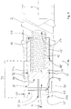
- FIG. 1 shows a schematic sectional view of an electrically conductive contact socket 2 of a connector.
- the contact socket 2 is constructed substantially rotationally symmetrical to a central longitudinal axis 4.
- the contact socket 2 is constructed for receiving a contact pin, not shown, in a receiving space 8 in a plugging direction 6. Furthermore, the contact socket 2 is designed to produce an electrically conductive connection between the contact socket 2 and the contact pin.
- the contact socket 2 is disposed within the connector and, as explained below, accessible through an opening in the connector.
- a preferably electrically non-conductive or electrically insulating closure element 10 is movably mounted within the contact socket 2.
- the closure element 10 is supported by means of a first pretensioning device 12 on an abutment portion 14 of the contact socket 2.
- the first biasing device 12 pushes the closure element 10 against the insertion direction 6.
- the closure element 10 In the position shown, the closure element 10 is in the insertion direction 6 at a stop 16 of the contact socket 2, which limits the movement of the closure element 10 in the insertion direction 6.
- the contact pin is not shown.
- the contact socket 2 has a contact section 22.
- the contact portion 22 comprises contact webs 24, which are separated by notches 26 from each other.
- the contact webs 24 have a transverse to the central longitudinal axis 4 oriented outer annular groove 28 in which a second biasing member 30 is arranged in the form of an annular spring.
- the second biasing means 30 thus surrounds the contact portion 22 at least in sections, to compress the contact portion 22 radially in the direction of the central longitudinal axis 4.
- the contact pin presses on delivery in the insertion direction on the distal end surface 32 of the closure element 10 and thus moves the closure element 10 in the insertion direction 6.
- the closure element is arranged against the insertion direction 6 moves, bringing a distal portion 34 with its cylindrical outer wall an inner contact surface 36 rests and thus forms an abutment to the second biasing means 30.
- the distal portion 34 has an outer diameter 38.
- the contact region 22 has a distal insertion bevel 40.
- an insertion region 42 for the closure element 10 adjoins the inner contact surface 36.
- the contact bush 2 has an annular fastening groove 44 for arrangement in an insulating body.
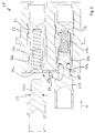
- FIG. 2 shows in schematic form a sectional view of a connector 50, wherein a respective contact pin 52 for explaining the function of the contact socket 2 is shown.
- the contact sockets 2 a and 2 b according to the embodiment in the FIG. 1 added.
- the distal portion 34 of the closure element 10 has the outer diameter 38, which corresponds to an outer diameter 54 of the male contact pin and / or with an inner diameter of the opening 60 substantially.
- the connector 50 has an insulating body 62, in which the contact socket 2 is arranged substantially stationary.
- the opening 60 is closed by the closure element 10 when the contact pin 52 is not supplied. If the contact pin 52 is supplied in the insertion direction 6, then the closure element 10 is displaced in the insertion direction 6. Here, the closure element 10 releases the inner contact surfaces 36 of the contact section 22 and the inner contact surfaces 36 can embrace the contact pin 52.
- the connector 50 comprises a sealing element 64, in which the opening 60 is executed.
- the sealing element 64 is substantially fixedly connected to the insulating body 62, however, compared to the insulating body 62 has a higher elasticity, so as to cooperate with the closure element 10, so that the opening 60 is preferably closed waterproof.
- the opening 60 can not be closed watertight and offers only a Berstoffschutz.
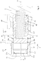
- FIG. 3 shows a further embodiment of the contact socket 2 in a schematic sectional view.
- the diameter increase 70 corresponds in such a way to the contact section 22 and in particular to the inner contact surfaces 36, so that the contact section 22 opens in the event of a plug-in operation of the contact pin 52.
- This pre-opening means that the contact webs 24 move radially outwardly by means of the diameter increase 70 and thus the contacting between the inner contact surface 36 and the contact pin 52 takes place only when the tip of the contact pin 52 when inserted into the contact socket 2, the inner contact surfaces 36th already happened.
- a portion 72 of the closure element 10 has the distal outer diameter 38 a. If the closure element 10 is in a position in which it lies with the outer diameter 38a in the region of the inner contact surfaces 36, then the inner contact surfaces 36 define an inner diameter 68. Starting from the distal outer diameter 38a, the diameter increases in a section 74 up to Diameter increase 70 too. In a section 76, the outer diameter in the insertion direction 6 decreases again to fall back in the proximal portion 78 of the distal portion 34 to the outer diameter 38 a. The proximal section 78 of the distal section 34 is adjoined by a proximal section 80 of the closure element 10.
- FIG. 4 is analogous to FIG. 2 an embodiment of the connector 50 is shown.
- the opening 60 in the insulating body 62 is executed.
- the opening 60 tapers counter to the insertion direction 6, with which the sections 72 and 74 can be accommodated at least partially in the opening 60.
Landscapes
- Connector Housings Or Holding Contact Members (AREA)
Applications Claiming Priority (1)
| Application Number | Priority Date | Filing Date | Title |
|---|---|---|---|
| DE102015213734.1A DE102015213734A1 (de) | 2015-07-21 | 2015-07-21 | Steckverbinder |
Publications (2)
| Publication Number | Publication Date |
|---|---|
| EP3121908A1 true EP3121908A1 (fr) | 2017-01-25 |
| EP3121908B1 EP3121908B1 (fr) | 2018-09-26 |
Family
ID=56235725
Family Applications (1)
| Application Number | Title | Priority Date | Filing Date |
|---|---|---|---|
| EP16176242.2A Active EP3121908B1 (fr) | 2015-07-21 | 2016-06-24 | Connecteur électrique à fiche |
Country Status (4)
| Country | Link |
|---|---|
| US (1) | US9748688B2 (fr) |
| EP (1) | EP3121908B1 (fr) |
| DE (1) | DE102015213734A1 (fr) |
| ES (1) | ES2703690T3 (fr) |
Cited By (3)
| Publication number | Priority date | Publication date | Assignee | Title |
|---|---|---|---|---|
| DE102017114510A1 (de) | 2017-06-29 | 2019-01-03 | Lisa Dräxlmaier GmbH | Hochstromkontaktbuchse |
| EP4290705A1 (fr) * | 2022-06-08 | 2023-12-13 | Ultratech | Connecteur électrique comportant un système de protection d'un utilisateur |
| WO2024115491A1 (fr) * | 2022-11-28 | 2024-06-06 | Era-Contact Gmbh | Prise de contact électrique et système de connexion et procédé d'établissement et de séparation d'une connexion électrique |
Families Citing this family (13)
| Publication number | Priority date | Publication date | Assignee | Title |
|---|---|---|---|---|
| US10062988B1 (en) * | 2016-09-19 | 2018-08-28 | Ardent Concepts, Inc. | Connector assembly for attaching a cable to an electrical device |
| JP6622252B2 (ja) * | 2017-06-09 | 2019-12-18 | 矢崎総業株式会社 | コネクタ装置 |
| EP3704821B1 (fr) | 2017-11-02 | 2021-12-01 | Nokia Technologies Oy | Indication de format de créneau à un groupe d'ue dans une cellule de station de base |
| CN107854049A (zh) * | 2017-11-15 | 2018-03-30 | 珠海格力电器股份有限公司 | 连接件的电连接结构及手持式吸尘器 |
| TWI637566B (zh) * | 2017-12-11 | 2018-10-01 | 緯創資通股份有限公司 | 電性連接組件 |
| GB2576156B (en) * | 2018-08-06 | 2021-08-18 | Siemens Ag | Connector and method of manufacture |
| CA3114127C (fr) * | 2018-09-28 | 2023-09-26 | Foshan Shunde Midea Electrical Heating Appliances Manufacturing Co., Ltd. | Coupleur d'alimentation, dispositif d'oscillateur a ultrasons, oscillateur a ultrasons, ensemble de montage, ensemble de corps de couvercle, ustensile de cuisson et appareil de ch auffage |
| CN111900561B (zh) * | 2020-07-14 | 2025-05-13 | 珠海市魅族科技有限公司 | 一种射频集成式插头及连接器 |
| DE102021206293A1 (de) * | 2021-06-18 | 2022-12-22 | Vorwerk & Co. Interholding Gesellschaft mit beschränkter Haftung | Elektrisches Haushaltsgerät mit Berührschutz für elektrische Kontakte |
| CN114221174B (zh) * | 2021-12-13 | 2024-05-14 | 四川华丰科技股份有限公司 | 一种具有分离助推作用的连接器 |
| DE102023112467A1 (de) * | 2023-05-11 | 2024-11-14 | Juice Technology AG | Steckverbindung zum Laden eines Elektrofahrzeugs |
| DE102023134637A1 (de) * | 2023-12-11 | 2025-06-12 | HARTING Automotive GmbH | Berührschutzelement für einen Steckverbinder |
| JP2025138300A (ja) * | 2024-03-11 | 2025-09-25 | 日本航空電子工業株式会社 | コネクタ |
Citations (6)
| Publication number | Priority date | Publication date | Assignee | Title |
|---|---|---|---|---|
| DE1202374B (de) | 1962-10-03 | 1965-10-07 | Bbc Brown Boveri & Cie | Aus zwei Kupplungsteilen bestehende elektrische Kupplung |
| US3491326A (en) * | 1967-05-19 | 1970-01-20 | Bolkow Gmbh | Disengageable electrical connector with contact protecting means |
| US3508188A (en) * | 1968-08-27 | 1970-04-21 | Jon R Buck | Underwater electrical quick disconnect |
| US5151040A (en) * | 1990-04-27 | 1992-09-29 | Kel Corporation | Electrical connector for repeated connection to integrated circuit grid array devices |
| US6309231B1 (en) * | 1999-09-02 | 2001-10-30 | Litton Precision Products International, Inc. | High current male and female power connector assembly |
| DE102006025611B3 (de) | 2006-05-24 | 2007-12-06 | Apparatebau Kirchheim-Teck Gmbh | Kontakthalter für einen Stecker oder eine Steckdose |
Family Cites Families (11)
| Publication number | Priority date | Publication date | Assignee | Title |
|---|---|---|---|---|
| FR2335068A1 (fr) | 1975-12-12 | 1977-07-08 | Parrier Andre | Prise electrique equipee d'un dispositif de securite |
| US4142770A (en) * | 1977-12-27 | 1979-03-06 | Exxon Production Research Company | Subsea electrical connector |
| US6494728B1 (en) * | 2000-01-14 | 2002-12-17 | Michael P. Gorman | Safety electrical connection system |
| US6767228B2 (en) * | 2001-06-01 | 2004-07-27 | Irwin G. Katz | Internal safety cover and method to prevent electrical shock |
| GB2411527B (en) * | 2004-02-26 | 2006-06-28 | Itt Mfg Enterprises Inc | Electrical connector |
| DE202004015917U1 (de) * | 2004-10-13 | 2005-01-20 | Virchow, Florian | Kontaktierungselement zum elektrischen Kontaktieren von Bauteilen |
| EP1829164B1 (fr) * | 2004-12-22 | 2008-04-23 | Carrier Kheops Bac | Connecteur électrique connectable dans l'eau ou un milieu liquide |
| US7140891B1 (en) * | 2006-06-02 | 2006-11-28 | Cheng Uei Precision Industry Co., Ltd. | Dustproof receptacle connector |
| US7972173B1 (en) * | 2010-05-07 | 2011-07-05 | Itt Manufacturing Enterprises, Inc. | Dual spring probe coaxial contact system |
| EP2477281A1 (fr) * | 2011-01-17 | 2012-07-18 | Jonas Brunvoll | Prise |
| JP6160767B2 (ja) * | 2014-03-17 | 2017-07-12 | 株式会社リコー | コネクタおよび該コネクタを備える電子機器 |
-
2015
- 2015-07-21 DE DE102015213734.1A patent/DE102015213734A1/de not_active Ceased
-
2016
- 2016-06-24 ES ES16176242T patent/ES2703690T3/es active Active
- 2016-06-24 EP EP16176242.2A patent/EP3121908B1/fr active Active
- 2016-07-19 US US15/214,279 patent/US9748688B2/en active Active
Patent Citations (6)
| Publication number | Priority date | Publication date | Assignee | Title |
|---|---|---|---|---|
| DE1202374B (de) | 1962-10-03 | 1965-10-07 | Bbc Brown Boveri & Cie | Aus zwei Kupplungsteilen bestehende elektrische Kupplung |
| US3491326A (en) * | 1967-05-19 | 1970-01-20 | Bolkow Gmbh | Disengageable electrical connector with contact protecting means |
| US3508188A (en) * | 1968-08-27 | 1970-04-21 | Jon R Buck | Underwater electrical quick disconnect |
| US5151040A (en) * | 1990-04-27 | 1992-09-29 | Kel Corporation | Electrical connector for repeated connection to integrated circuit grid array devices |
| US6309231B1 (en) * | 1999-09-02 | 2001-10-30 | Litton Precision Products International, Inc. | High current male and female power connector assembly |
| DE102006025611B3 (de) | 2006-05-24 | 2007-12-06 | Apparatebau Kirchheim-Teck Gmbh | Kontakthalter für einen Stecker oder eine Steckdose |
Cited By (7)
| Publication number | Priority date | Publication date | Assignee | Title |
|---|---|---|---|---|
| DE102017114510A1 (de) | 2017-06-29 | 2019-01-03 | Lisa Dräxlmaier GmbH | Hochstromkontaktbuchse |
| WO2019002522A1 (fr) | 2017-06-29 | 2019-01-03 | Lisa Dräxlmaier GmbH | Douille de contact pour courant fort |
| DE102017114510B4 (de) | 2017-06-29 | 2023-10-05 | Lisa Dräxlmaier GmbH | Hochstromkontaktbuchse |
| EP4290705A1 (fr) * | 2022-06-08 | 2023-12-13 | Ultratech | Connecteur électrique comportant un système de protection d'un utilisateur |
| FR3136603A1 (fr) * | 2022-06-08 | 2023-12-15 | Ultratech | Connecteur électrique comportant un système de protection d’un utilisateur |
| US12562522B2 (en) | 2022-06-08 | 2026-02-24 | Ultratech | Electrical connector comprising a user protective system |
| WO2024115491A1 (fr) * | 2022-11-28 | 2024-06-06 | Era-Contact Gmbh | Prise de contact électrique et système de connexion et procédé d'établissement et de séparation d'une connexion électrique |
Also Published As
| Publication number | Publication date |
|---|---|
| DE102015213734A1 (de) | 2017-01-26 |
| ES2703690T3 (es) | 2019-03-12 |
| US9748688B2 (en) | 2017-08-29 |
| US20170025786A1 (en) | 2017-01-26 |
| EP3121908B1 (fr) | 2018-09-26 |
Similar Documents
| Publication | Publication Date | Title |
|---|---|---|
| EP3121908B1 (fr) | Connecteur électrique à fiche | |
| EP1926179B1 (fr) | Connecteur à fiches pour conducteurs électriques assemblés | |
| EP3262722B1 (fr) | Connexion enfichable comprenant un dispositif de verrouillage | |
| EP3259810B1 (fr) | Connecteur avec un élément amortisseur | |
| DE202010009597U1 (de) | Steckverbinder mit einer radial wirkenden Rasteinrichtung | |
| DE102015211658B4 (de) | Steckverbinder und Gegensteckverbinder sowie Steckverbindersystem | |
| DE10320594B3 (de) | Elektrische Steckkupplung | |
| EP3176885B1 (fr) | Systeme de connecteur a fiches | |
| DE102023105968A1 (de) | Geschirmter PushPull-Stecker mit Schirmfeder | |
| EP3084896B1 (fr) | Système de connexion | |
| DE102015114080B4 (de) | Elektrischer steckverbinder und damit ausgestattete elektrische steckverbindung | |
| EP2092614B1 (fr) | Fiche coaxiale à relier à un connecteur coaxial bnc | |
| DE102017004266B4 (de) | Steckverbinder und Steckverbindersystem | |
| WO2021028150A1 (fr) | Couplage de traction électrique et couplage de traction équipé dudit couplage de traction électrique | |
| DE102016100382B3 (de) | Steckverbinder | |
| DE102019115324B4 (de) | Steckeranordnung, vorrichtung und verfahren zum bilden einer elektrisch leitenden verbindung | |
| DE102023112467A1 (de) | Steckverbindung zum Laden eines Elektrofahrzeugs | |
| DE10303243B3 (de) | Elektrischer Schnellkupplungssteckverbinder | |
| DE102019117698A1 (de) | Anschlusseinrichtung zum Anschließen einer elektrischen Leitung | |
| DE102007027760A1 (de) | Zweiteilige Steckverbindereinrichtung | |
| DE102023105616A1 (de) | Manuelles Betätigungswerkzeug für einen elektrischen Steckverbinder oder eine elektrische Anschlussklemme | |
| DE20307156U1 (de) | Elektrische Steckkupplung | |
| WO2012136433A1 (fr) | Connecteur enfichable à élément de verrouillage | |
| DE202007005414U1 (de) | Anschlusssystem mit einem Steckverbinder | |
| DE102019133037A1 (de) | Steckverbindung zur Übertragung elektrischer Energie |
Legal Events
| Date | Code | Title | Description |
|---|---|---|---|
| PUAI | Public reference made under article 153(3) epc to a published international application that has entered the european phase |
Free format text: ORIGINAL CODE: 0009012 |
|
| STAA | Information on the status of an ep patent application or granted ep patent |
Free format text: STATUS: THE APPLICATION HAS BEEN PUBLISHED |
|
| AK | Designated contracting states |
Kind code of ref document: A1 Designated state(s): AL AT BE BG CH CY CZ DE DK EE ES FI FR GB GR HR HU IE IS IT LI LT LU LV MC MK MT NL NO PL PT RO RS SE SI SK SM TR |
|
| AX | Request for extension of the european patent |
Extension state: BA ME |
|
| STAA | Information on the status of an ep patent application or granted ep patent |
Free format text: STATUS: REQUEST FOR EXAMINATION WAS MADE |
|
| 17P | Request for examination filed |
Effective date: 20170725 |
|
| RBV | Designated contracting states (corrected) |
Designated state(s): AL AT BE BG CH CY CZ DE DK EE ES FI FR GB GR HR HU IE IS IT LI LT LU LV MC MK MT NL NO PL PT RO RS SE SI SK SM TR |
|
| STAA | Information on the status of an ep patent application or granted ep patent |
Free format text: STATUS: EXAMINATION IS IN PROGRESS |
|
| 17Q | First examination report despatched |
Effective date: 20170928 |
|
| GRAP | Despatch of communication of intention to grant a patent |
Free format text: ORIGINAL CODE: EPIDOSNIGR1 |
|
| STAA | Information on the status of an ep patent application or granted ep patent |
Free format text: STATUS: GRANT OF PATENT IS INTENDED |
|
| RIC1 | Information provided on ipc code assigned before grant |
Ipc: H01R 13/11 20060101ALI20180122BHEP Ipc: H01R 13/453 20060101AFI20180122BHEP Ipc: H01R 13/52 20060101ALI20180122BHEP |
|
| INTG | Intention to grant announced |
Effective date: 20180208 |
|
| GRAS | Grant fee paid |
Free format text: ORIGINAL CODE: EPIDOSNIGR3 |
|
| GRAJ | Information related to disapproval of communication of intention to grant by the applicant or resumption of examination proceedings by the epo deleted |
Free format text: ORIGINAL CODE: EPIDOSDIGR1 |
|
| GRAL | Information related to payment of fee for publishing/printing deleted |
Free format text: ORIGINAL CODE: EPIDOSDIGR3 |
|
| STAA | Information on the status of an ep patent application or granted ep patent |
Free format text: STATUS: EXAMINATION IS IN PROGRESS |
|
| GRAP | Despatch of communication of intention to grant a patent |
Free format text: ORIGINAL CODE: EPIDOSNIGR1 |
|
| STAA | Information on the status of an ep patent application or granted ep patent |
Free format text: STATUS: GRANT OF PATENT IS INTENDED |
|
| INTC | Intention to grant announced (deleted) | ||
| INTG | Intention to grant announced |
Effective date: 20180709 |
|
| GRAA | (expected) grant |
Free format text: ORIGINAL CODE: 0009210 |
|
| STAA | Information on the status of an ep patent application or granted ep patent |
Free format text: STATUS: THE PATENT HAS BEEN GRANTED |
|
| AK | Designated contracting states |
Kind code of ref document: B1 Designated state(s): AL AT BE BG CH CY CZ DE DK EE ES FI FR GB GR HR HU IE IS IT LI LT LU LV MC MK MT NL NO PL PT RO RS SE SI SK SM TR |
|
| REG | Reference to a national code |
Ref country code: GB Ref legal event code: FG4D Free format text: NOT ENGLISH |
|
| REG | Reference to a national code |
Ref country code: CH Ref legal event code: EP |
|
| REG | Reference to a national code |
Ref country code: AT Ref legal event code: REF Ref document number: 1047133 Country of ref document: AT Kind code of ref document: T Effective date: 20181015 |
|
| REG | Reference to a national code |
Ref country code: IE Ref legal event code: FG4D Free format text: LANGUAGE OF EP DOCUMENT: GERMAN |
|
| REG | Reference to a national code |
Ref country code: DE Ref legal event code: R096 Ref document number: 502016002066 Country of ref document: DE |
|
| REG | Reference to a national code |
Ref country code: NL Ref legal event code: MP Effective date: 20180926 |
|
| PG25 | Lapsed in a contracting state [announced via postgrant information from national office to epo] |
Ref country code: GR Free format text: LAPSE BECAUSE OF FAILURE TO SUBMIT A TRANSLATION OF THE DESCRIPTION OR TO PAY THE FEE WITHIN THE PRESCRIBED TIME-LIMIT Effective date: 20181227 Ref country code: FI Free format text: LAPSE BECAUSE OF FAILURE TO SUBMIT A TRANSLATION OF THE DESCRIPTION OR TO PAY THE FEE WITHIN THE PRESCRIBED TIME-LIMIT Effective date: 20180926 Ref country code: NO Free format text: LAPSE BECAUSE OF FAILURE TO SUBMIT A TRANSLATION OF THE DESCRIPTION OR TO PAY THE FEE WITHIN THE PRESCRIBED TIME-LIMIT Effective date: 20181226 Ref country code: RS Free format text: LAPSE BECAUSE OF FAILURE TO SUBMIT A TRANSLATION OF THE DESCRIPTION OR TO PAY THE FEE WITHIN THE PRESCRIBED TIME-LIMIT Effective date: 20180926 Ref country code: LT Free format text: LAPSE BECAUSE OF FAILURE TO SUBMIT A TRANSLATION OF THE DESCRIPTION OR TO PAY THE FEE WITHIN THE PRESCRIBED TIME-LIMIT Effective date: 20180926 Ref country code: BG Free format text: LAPSE BECAUSE OF FAILURE TO SUBMIT A TRANSLATION OF THE DESCRIPTION OR TO PAY THE FEE WITHIN THE PRESCRIBED TIME-LIMIT Effective date: 20181226 |
|
| REG | Reference to a national code |
Ref country code: LT Ref legal event code: MG4D |
|
| PG25 | Lapsed in a contracting state [announced via postgrant information from national office to epo] |
Ref country code: LV Free format text: LAPSE BECAUSE OF FAILURE TO SUBMIT A TRANSLATION OF THE DESCRIPTION OR TO PAY THE FEE WITHIN THE PRESCRIBED TIME-LIMIT Effective date: 20180926 Ref country code: AL Free format text: LAPSE BECAUSE OF FAILURE TO SUBMIT A TRANSLATION OF THE DESCRIPTION OR TO PAY THE FEE WITHIN THE PRESCRIBED TIME-LIMIT Effective date: 20180926 Ref country code: HR Free format text: LAPSE BECAUSE OF FAILURE TO SUBMIT A TRANSLATION OF THE DESCRIPTION OR TO PAY THE FEE WITHIN THE PRESCRIBED TIME-LIMIT Effective date: 20180926 |
|
| REG | Reference to a national code |
Ref country code: ES Ref legal event code: FG2A Ref document number: 2703690 Country of ref document: ES Kind code of ref document: T3 Effective date: 20190312 |
|
| PG25 | Lapsed in a contracting state [announced via postgrant information from national office to epo] |
Ref country code: NL Free format text: LAPSE BECAUSE OF FAILURE TO SUBMIT A TRANSLATION OF THE DESCRIPTION OR TO PAY THE FEE WITHIN THE PRESCRIBED TIME-LIMIT Effective date: 20180926 Ref country code: PL Free format text: LAPSE BECAUSE OF FAILURE TO SUBMIT A TRANSLATION OF THE DESCRIPTION OR TO PAY THE FEE WITHIN THE PRESCRIBED TIME-LIMIT Effective date: 20180926 Ref country code: IS Free format text: LAPSE BECAUSE OF FAILURE TO SUBMIT A TRANSLATION OF THE DESCRIPTION OR TO PAY THE FEE WITHIN THE PRESCRIBED TIME-LIMIT Effective date: 20190126 Ref country code: CZ Free format text: LAPSE BECAUSE OF FAILURE TO SUBMIT A TRANSLATION OF THE DESCRIPTION OR TO PAY THE FEE WITHIN THE PRESCRIBED TIME-LIMIT Effective date: 20180926 Ref country code: RO Free format text: LAPSE BECAUSE OF FAILURE TO SUBMIT A TRANSLATION OF THE DESCRIPTION OR TO PAY THE FEE WITHIN THE PRESCRIBED TIME-LIMIT Effective date: 20180926 Ref country code: EE Free format text: LAPSE BECAUSE OF FAILURE TO SUBMIT A TRANSLATION OF THE DESCRIPTION OR TO PAY THE FEE WITHIN THE PRESCRIBED TIME-LIMIT Effective date: 20180926 |
|
| PG25 | Lapsed in a contracting state [announced via postgrant information from national office to epo] |
Ref country code: SK Free format text: LAPSE BECAUSE OF FAILURE TO SUBMIT A TRANSLATION OF THE DESCRIPTION OR TO PAY THE FEE WITHIN THE PRESCRIBED TIME-LIMIT Effective date: 20180926 Ref country code: SM Free format text: LAPSE BECAUSE OF FAILURE TO SUBMIT A TRANSLATION OF THE DESCRIPTION OR TO PAY THE FEE WITHIN THE PRESCRIBED TIME-LIMIT Effective date: 20180926 Ref country code: PT Free format text: LAPSE BECAUSE OF FAILURE TO SUBMIT A TRANSLATION OF THE DESCRIPTION OR TO PAY THE FEE WITHIN THE PRESCRIBED TIME-LIMIT Effective date: 20190126 |
|
| REG | Reference to a national code |
Ref country code: DE Ref legal event code: R097 Ref document number: 502016002066 Country of ref document: DE |
|
| PG25 | Lapsed in a contracting state [announced via postgrant information from national office to epo] |
Ref country code: DK Free format text: LAPSE BECAUSE OF FAILURE TO SUBMIT A TRANSLATION OF THE DESCRIPTION OR TO PAY THE FEE WITHIN THE PRESCRIBED TIME-LIMIT Effective date: 20180926 |
|
| PLBE | No opposition filed within time limit |
Free format text: ORIGINAL CODE: 0009261 |
|
| STAA | Information on the status of an ep patent application or granted ep patent |
Free format text: STATUS: NO OPPOSITION FILED WITHIN TIME LIMIT |
|
| 26N | No opposition filed |
Effective date: 20190627 |
|
| PG25 | Lapsed in a contracting state [announced via postgrant information from national office to epo] |
Ref country code: SI Free format text: LAPSE BECAUSE OF FAILURE TO SUBMIT A TRANSLATION OF THE DESCRIPTION OR TO PAY THE FEE WITHIN THE PRESCRIBED TIME-LIMIT Effective date: 20180926 |
|
| PG25 | Lapsed in a contracting state [announced via postgrant information from national office to epo] |
Ref country code: MC Free format text: LAPSE BECAUSE OF FAILURE TO SUBMIT A TRANSLATION OF THE DESCRIPTION OR TO PAY THE FEE WITHIN THE PRESCRIBED TIME-LIMIT Effective date: 20180926 |
|
| REG | Reference to a national code |
Ref country code: CH Ref legal event code: PL |
|
| REG | Reference to a national code |
Ref country code: BE Ref legal event code: MM Effective date: 20190630 |
|
| PG25 | Lapsed in a contracting state [announced via postgrant information from national office to epo] |
Ref country code: TR Free format text: LAPSE BECAUSE OF FAILURE TO SUBMIT A TRANSLATION OF THE DESCRIPTION OR TO PAY THE FEE WITHIN THE PRESCRIBED TIME-LIMIT Effective date: 20180926 |
|
| PG25 | Lapsed in a contracting state [announced via postgrant information from national office to epo] |
Ref country code: IE Free format text: LAPSE BECAUSE OF NON-PAYMENT OF DUE FEES Effective date: 20190624 |
|
| PG25 | Lapsed in a contracting state [announced via postgrant information from national office to epo] |
Ref country code: LU Free format text: LAPSE BECAUSE OF NON-PAYMENT OF DUE FEES Effective date: 20190624 Ref country code: LI Free format text: LAPSE BECAUSE OF NON-PAYMENT OF DUE FEES Effective date: 20190630 Ref country code: CH Free format text: LAPSE BECAUSE OF NON-PAYMENT OF DUE FEES Effective date: 20190630 Ref country code: BE Free format text: LAPSE BECAUSE OF NON-PAYMENT OF DUE FEES Effective date: 20190630 |
|
| PG25 | Lapsed in a contracting state [announced via postgrant information from national office to epo] |
Ref country code: CY Free format text: LAPSE BECAUSE OF FAILURE TO SUBMIT A TRANSLATION OF THE DESCRIPTION OR TO PAY THE FEE WITHIN THE PRESCRIBED TIME-LIMIT Effective date: 20180926 |
|
| PG25 | Lapsed in a contracting state [announced via postgrant information from national office to epo] |
Ref country code: SE Free format text: LAPSE BECAUSE OF NON-PAYMENT OF DUE FEES Effective date: 20180926 |
|
| PG25 | Lapsed in a contracting state [announced via postgrant information from national office to epo] |
Ref country code: HU Free format text: LAPSE BECAUSE OF FAILURE TO SUBMIT A TRANSLATION OF THE DESCRIPTION OR TO PAY THE FEE WITHIN THE PRESCRIBED TIME-LIMIT; INVALID AB INITIO Effective date: 20160624 Ref country code: MT Free format text: LAPSE BECAUSE OF FAILURE TO SUBMIT A TRANSLATION OF THE DESCRIPTION OR TO PAY THE FEE WITHIN THE PRESCRIBED TIME-LIMIT Effective date: 20180926 |
|
| PG25 | Lapsed in a contracting state [announced via postgrant information from national office to epo] |
Ref country code: MK Free format text: LAPSE BECAUSE OF FAILURE TO SUBMIT A TRANSLATION OF THE DESCRIPTION OR TO PAY THE FEE WITHIN THE PRESCRIBED TIME-LIMIT Effective date: 20180926 |
|
| REG | Reference to a national code |
Ref country code: AT Ref legal event code: MM01 Ref document number: 1047133 Country of ref document: AT Kind code of ref document: T Effective date: 20210624 |
|
| PG25 | Lapsed in a contracting state [announced via postgrant information from national office to epo] |
Ref country code: AT Free format text: LAPSE BECAUSE OF NON-PAYMENT OF DUE FEES Effective date: 20210624 |
|
| P01 | Opt-out of the competence of the unified patent court (upc) registered |
Effective date: 20230528 |
|
| PGFP | Annual fee paid to national office [announced via postgrant information from national office to epo] |
Ref country code: ES Payment date: 20250701 Year of fee payment: 10 |
|
| PGFP | Annual fee paid to national office [announced via postgrant information from national office to epo] |
Ref country code: GB Payment date: 20260520 Year of fee payment: 11 |
|
| PGFP | Annual fee paid to national office [announced via postgrant information from national office to epo] |
Ref country code: IT Payment date: 20260520 Year of fee payment: 11 |
|
| PGFP | Annual fee paid to national office [announced via postgrant information from national office to epo] |
Ref country code: DE Payment date: 20260520 Year of fee payment: 11 |
|
| PGFP | Annual fee paid to national office [announced via postgrant information from national office to epo] |
Ref country code: FR Payment date: 20260521 Year of fee payment: 11 |