EP3296493B1 - Tragsystem für eine schiebetür - Google Patents
Tragsystem für eine schiebetür Download PDFInfo
- Publication number
- EP3296493B1 EP3296493B1 EP17173480.9A EP17173480A EP3296493B1 EP 3296493 B1 EP3296493 B1 EP 3296493B1 EP 17173480 A EP17173480 A EP 17173480A EP 3296493 B1 EP3296493 B1 EP 3296493B1
- Authority
- EP
- European Patent Office
- Prior art keywords
- bolt
- support system
- drive
- limiting device
- locking
- Prior art date
- Legal status (The legal status is an assumption and is not a legal conclusion. Google has not performed a legal analysis and makes no representation as to the accuracy of the status listed.)
- Active
Links
Images


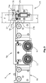

Classifications
-
- E—FIXED CONSTRUCTIONS
- E05—LOCKS; KEYS; WINDOW OR DOOR FITTINGS; SAFES
- E05D—HINGES OR SUSPENSION DEVICES FOR DOORS, WINDOWS OR WINGS
- E05D15/00—Suspension arrangements for wings
- E05D15/06—Suspension arrangements for wings for wings sliding horizontally more or less in their own plane
- E05D15/0621—Details, e.g. suspension or supporting guides
- E05D15/0626—Details, e.g. suspension or supporting guides for wings suspended at the top
- E05D15/063—Details, e.g. suspension or supporting guides for wings suspended at the top on wheels with fixed axis
- E05D15/0634—Details, e.g. suspension or supporting guides for wings suspended at the top on wheels with fixed axis with height adjustment
-
- E—FIXED CONSTRUCTIONS
- E05—LOCKS; KEYS; WINDOW OR DOOR FITTINGS; SAFES
- E05B—LOCKS; ACCESSORIES THEREFOR; HANDCUFFS
- E05B65/00—Locks or fastenings for special use
- E05B65/0025—Locks or fastenings for special use for glass wings
-
- E—FIXED CONSTRUCTIONS
- E05—LOCKS; KEYS; WINDOW OR DOOR FITTINGS; SAFES
- E05B—LOCKS; ACCESSORIES THEREFOR; HANDCUFFS
- E05B65/00—Locks or fastenings for special use
- E05B65/08—Locks or fastenings for special use for sliding wings
- E05B65/0811—Locks or fastenings for special use for sliding wings the bolts pivoting about an axis perpendicular to the wings
- E05B65/0829—Locks or fastenings for special use for sliding wings the bolts pivoting about an axis perpendicular to the wings mounted on the slide guide, e.g. the rail
-
- E—FIXED CONSTRUCTIONS
- E05—LOCKS; KEYS; WINDOW OR DOOR FITTINGS; SAFES
- E05D—HINGES OR SUSPENSION DEVICES FOR DOORS, WINDOWS OR WINGS
- E05D5/00—Construction of single parts, e.g. the parts for attachment
- E05D5/02—Parts for attachment, e.g. flaps
- E05D5/0246—Parts for attachment, e.g. flaps for attachment to glass panels
-
- E—FIXED CONSTRUCTIONS
- E05—LOCKS; KEYS; WINDOW OR DOOR FITTINGS; SAFES
- E05Y—INDEXING SCHEME ASSOCIATED WITH SUBCLASSES E05D AND E05F, RELATING TO CONSTRUCTION ELEMENTS, ELECTRIC CONTROL, POWER SUPPLY, POWER SIGNAL OR TRANSMISSION, USER INTERFACES, MOUNTING OR COUPLING, DETAILS, ACCESSORIES, AUXILIARY OPERATIONS NOT OTHERWISE PROVIDED FOR, APPLICATION THEREOF
- E05Y2201/00—Constructional elements; Accessories therefor
- E05Y2201/20—Brakes; Disengaging means; Holders; Stops; Valves; Accessories therefor
- E05Y2201/218—Holders
- E05Y2201/22—Locks
-
- E—FIXED CONSTRUCTIONS
- E05—LOCKS; KEYS; WINDOW OR DOOR FITTINGS; SAFES
- E05Y—INDEXING SCHEME ASSOCIATED WITH SUBCLASSES E05D AND E05F, RELATING TO CONSTRUCTION ELEMENTS, ELECTRIC CONTROL, POWER SUPPLY, POWER SIGNAL OR TRANSMISSION, USER INTERFACES, MOUNTING OR COUPLING, DETAILS, ACCESSORIES, AUXILIARY OPERATIONS NOT OTHERWISE PROVIDED FOR, APPLICATION THEREOF
- E05Y2600/00—Mounting or coupling arrangements for elements provided for in this subclass
- E05Y2600/50—Mounting methods; Positioning
- E05Y2600/502—Clamping
-
- E—FIXED CONSTRUCTIONS
- E05—LOCKS; KEYS; WINDOW OR DOOR FITTINGS; SAFES
- E05Y—INDEXING SCHEME ASSOCIATED WITH SUBCLASSES E05D AND E05F, RELATING TO CONSTRUCTION ELEMENTS, ELECTRIC CONTROL, POWER SUPPLY, POWER SIGNAL OR TRANSMISSION, USER INTERFACES, MOUNTING OR COUPLING, DETAILS, ACCESSORIES, AUXILIARY OPERATIONS NOT OTHERWISE PROVIDED FOR, APPLICATION THEREOF
- E05Y2900/00—Application of doors, windows, wings or fittings thereof
- E05Y2900/10—Application of doors, windows, wings or fittings thereof for buildings or parts thereof
- E05Y2900/13—Type of wing
- E05Y2900/132—Doors
Definitions
- the present invention relates to a support system for a sliding door according to the preamble of claim 1.
- Support systems for sliding doors in particular for sliding glass doors, usually have a running rail in which a door leaf is guided over a drive.
- the path of the drive and thus of the door leaf is limited by a limiting device.
- Such a support system is, for example, off DE 20 2007 014 567 U1 previously known.
- EP 2 607 580 A2 discloses a sliding door with a lock device according to the preamble of claim 1.
- the lock device here consists of a lock that is fastened via a running rail and a flat arm protruding from the drive in the direction of travel, which acts as a gripping element for a bolt of the lock.
- the bolt of the lock can be pivoted about a horizontal axis which runs in the direction of the running rail. This is for the Pivoting the bolt in a direction transverse to the longitudinal direction of the running rail requires more space.
- a larger space requirement is also required in the longitudinal direction of the drive for the arrangement of the limiting device.
- the drive of the door leaf should also be arranged at a small distance from the side edge of the door leaf so that the door leaf can be guided with high stability.
- the invention is defined by the features of claim 1.
- the support system according to the invention for a sliding door has a running rail with at least one drive for guiding the door leaf of the sliding door, a limiting device for the drive that limits the path of the door leaf and a lock device via which the door leaf can be locked in an end position.
- the lock device has a locking device and an engaging element. The locking device interacts with the engaging element for locking, the engaging element being arranged on the carriage, and the locking device forming a structural unit with the limiting device.
- the invention is characterized in that the locking device has a locking device and an automatic restoring force moves the locking device into an unlocking position, the locking device via a drive device can be actuated into a locking position against the automatic restoring force.
- the locking device By providing a locking device, which forms a structural unit with the limiting device, the locking device can be made very compact, so that the installation space in the longitudinal direction of the running rail can be kept very small.
- the end position of the door leaf can either be its closed end position, so that the door leaf is to be prevented from opening via the lock device, or its open end position, with the door leaf being prevented from closing via the lock device.
- the gripping element engages behind the bolt, whereby the bolt blocks a movement of the door leaf in at least one direction.
- the support system can provide a damper device with a pull-in function, the damper device initially braking the door leaf when moving into the end position and then driving it in the direction of an end position.
- the running rail can have a running surface for running rollers of the drive, so that the drive only has rollers on one side of the door leaf.
- the door leaf can thus advantageously be hooked into the running rail from one side of the running rail in a direction transverse to the running rail.
- running rail enables the running rail to be made very compact in the horizontal direction transversely to the longitudinal direction of the running rail.
- the drive can for example consist of a fastening device, for example a clamping device, and be fastened to the door leaf via the fastening device.
- a relative displacement in the vertical direction can be possible between the fastening device and the carriage, whereby a height adjustment of the door leaf is made possible.
- the rollers can be arranged on the carriage.
- a stop device can be provided on the carriage, preferably on the fastening device of the carriage, or on the delimitation device which absorbs residual energy when the carriage strikes the delimitation device.
- the stop device can, for example, be designed as a rubber buffer.
- the door leaves of the sliding door can be made of glass, for example.
- the limiting device when the door leaf is closed, the limiting device is arranged at least partially laterally next to the door leaf, i.e. in the horizontal direction transversely to the longitudinal axis of the running rail next to the door leaf.
- the installation space required for the support system in the longitudinal direction of the running rail is very small.
- the structural unit formed according to the invention comprising the delimitation device and the locking device also enables applications in which the door leaf, in the closed state, is intended to terminate with a wall adjoining the running rail in the longitudinal direction.
- the door leaf protrudes in the longitudinal direction of the running rail over the drive with a length that is approximately Extent of the structural unit from locking device and limiting device in the longitudinal direction of the running rail corresponds. Due to the compact design of the structural unit consisting of the limiting device and locking device, the invention enables the drive to be arranged very close to the side edge of the door leaf with such a design, which enables stable door guidance.
- the automatic restoring force is generated by gravity, so that the bolt falls into the unlocking position due to its weight due to the force of gravity.
- the bolt can for example consist of stainless steel. This ensures that the bolt, due to its own weight, which is caused by the relatively high density of the stainless steel, advantageously falls into the unlocking position.
- Other parts of the support system such as the running gear, the running rail or the limiting device, can consist entirely or in part of aluminum.
- the drive device actuates the bolt by means of a drive element which can be actuated in a vertical direction.
- the drive element is actuated in the opposite direction to the force of gravity providing the automatic restoring force.
- the installation space that is necessary for the drive device in the longitudinal direction of the running rail is kept very small.
- the latch can be operated electrically or manually, for example.
- the drive device has an electromagnet, the drive element being raised into its locking position when the electromagnet is actuated.
- the drive device can advantageously be driven electrically and, moreover, the installation space for the drive device can be kept very small.
- an electromagnet in the drive device also has the advantage that in the event of a failure of the electrical power supply, the electromagnet is automatically switched off and thus the drive element can fall into the locking position due to gravity. This releases the bolt and can fall into its unlocked position due to the automatic restoring force. If the power supply to the drive device fails, the lock device is automatically unlocked and people are prevented from being locked in.
- the gripping element is designed as an arm extending in the direction of the end position of the drive.
- the gripping element is preferably arranged on the carriage.
- the lock device is independent of the height adjustment, so that a reliable function of the lock device is guaranteed even after a height adjustment of the sliding door.
- the limiting device can have a recess into which the arm engages when the drive is moved into the end position. It can be provided that the bolt is arranged in the bottom of the recess. The bolt can for example be embedded in the bottom of the recess. At the When the drive is moved into the end position, the arm engages in the recess of the limiting device and the bolt can engage the arm from below in order to effect the locking.
- a retaining element is arranged opposite the bolt, the gripping element being arranged between the bolt and the retaining element in the end position of the drive.
- the holding element serves as a counter-bearing for the gripping element, so that it is prevented that the gripping element can be pushed in a direction away from the bolt and thus the gripping element is pushed out of the locking position.
- the holding element can, for example, have a sliding bevel that guides the gripping element. This ensures that when the bolt is in the locking position, for example, without the engaging element already being arranged in the position for locking, when the drive continues to move towards the end position, the engaging element is guided by the sliding bevel into the correct position.
- the gripping element can, for example, press the bolt out of the locking position against the force provided by the drive device in the direction of the unlocking position, which then snaps back into the locking position.
- the provision of a drive device with an electromagnet is particularly advantageous, since the bolt can be snapped in by the engagement element briefly pushing the bolt against the magnetic force of the electromagnet in the direction of the unlocking position.
- the gripping element can have a sliding bevel at the front end which presses the bolt in the direction of the unlocking position.
- the latch is preferably arranged to be pivotable.
- the bolt can be pivotable about a horizontal axis transversely to the longitudinal direction of the running rail. As a result, the space required by the bolt in the horizontal direction transversely to the longitudinal direction of the running rail is kept low, since the bolt is pivoted only in one plane which extends vertically in the longitudinal direction of the running rail.
- a stop for the bolt can be provided in the limiting device. This prevents the bolt from being pushed too far in the direction of its locking position in the event of a malfunction of the drive device, so that, for example, the gripping element hits a blocked bolt when the drive is moved into its end position, thereby preventing locking.
- the bolt has a locking surface, in the locking position cooperates with a bolt contact surface of the engagement element and that the drive, preferably the fastening device of the drive, has a front surface which in the end position of the drive on a stop surface the limiting device is applied, with a horizontal distance D in the longitudinal direction of the running rail between the bolt contact surface and the front surface and a horizontal distance d in the longitudinal direction of the running rail between the locking surface in the unlocking position and the stop surface of the limiting device, with Dd ⁇ 0.5mm, preferably 1mm ⁇ Dd ⁇ 3mm.
- the front surface of the drive can be arranged on the drive itself or, in the case of a stop device arranged on the drive, on the stop device.
- the stop surface of the limiting device is arranged on the limiting device itself or, in the case of a stop device arranged on the limiting device, on the stop device.
- the horizontal distances D, d relate to transom contact surfaces and transom surfaces that are not vertical, For example, on the center point of the respective surface or the point of contact between the bolt contact surface and the bolt surface.
- the inventive arrangement of the locking surface, stop surface of the limiting device, locking contact surface and front surface of the drive ensures that the bolt can also be moved into the locking position if the door has not fully moved up to the limiting device, because, for example, contamination in the running rail or is present on a floor guide of the door leaf. It is also ensured that if the door leaf moves very quickly into the end position and the drive hits the stop device or the stop device hits the limiting device and the stop device deflects as a result and the door springs back, there is sufficient time for the bolt to snap into place. In other words: It is ensured that the door does not spring back from its end position without the bolt being able to snap into the locking position.
- the delimitation device forms a housing for the locking device which has an access opening to the locking device, the drive element and / or the drive device, the access opening being arranged on the side facing the running rail.
- the bolt, the drive element and / or the drive device are advantageously accessible via the access opening in order, for example, to assemble or service these parts.
- the access opening can be closed with a plate, for example.
- Providing the access opening on the side facing the running rail has the advantage that after the limiting device has been inserted into the running rail, the bolt, the drive element and / or the drive device are no longer accessible from the outside so that they cannot be manipulated.
- the plate closing the access opening prevents dirt particles from the environment from reaching the bolt, the drive device or the drive element. Furthermore, the plate can also serve as a mounting fastening means for, for example, the bolt or the drive device.
- the limiting device is fastened in a clamping manner in the running rail by means of a clamping screw, the clamping screw being arranged at an angle to a vertical plane running in the longitudinal direction of the running rail.
- the limiting device can thus be fastened to the running rail in an advantageous manner. Due to the clamping fastening, an adjustment of the limiting device is possible in a simple manner during the assembly of the limiting device.
- the limiting device can, for example, rest against the running surface of the running rail.
- the inclined arrangement of the clamping screw ensures that in the end position of the door leaf, the door leaf blocks access to the clamping screw, so that manipulation of the limiting device is not possible. In the case of a clamping screw that is arranged vertically, access to this would still be possible in the end position of the door leaf by operating it vertically from below.
- the arrangement according to the invention thus increases the security of the lock device.
- the inclined arrangement of the clamping screw can also be designed in such a way that the clamping screw cannot be operated when a panel is arranged on the running rail and covers the travel space in the running rail for the drive and the drive itself.
- the recess has a length L in the longitudinal direction of the running rail and the part of the arm protruding from the carriage in the longitudinal direction of the running rail has a length I, where L ⁇ I.
- a run-out zone for the arm is thus formed in the recess, so that if a deflection, for example a stop device, occurs when the drive starts up at the limiting device, the arm does not strike the recess. It is preferably provided that the following applies: L-I ⁇ maximum spring deflection of the stop device.
- the length I reproduces the part of the arm protruding in the longitudinal direction of the running rail over the front surface of the stop device.
- the electrically operated lock device can, for example, be part of an automatic door.
- the lock device can be controlled together with a drive for the automatic door, so that, for example, the lock is first unlocked and then the automatic door is moved. After a specified time, the automatic door moves back to the closed end position and the lock locks automatically.
- the lock can also have been locked beforehand and when the door leaf is moved into the closed end position, it is locked using the snap-in function.
- the lock device can be locked each time the door is closed or, for example, timed so that the lock device is unlocked over a predetermined period of time in which the automatic door can be opened and closed at any time and is locked over a period of time so that the door cannot be opened .
- a support system 1 according to the invention for a sliding door 100 is shown schematically in a perspective view.
- the sliding door 100 has a door leaf 105 which is designed as a glass door leaf.
- the support system 1 has a running rail 3 which is covered by a panel 5 on the side facing the viewer.
- the running rail 3 has a running surface 7 for one in the Figs. 2 and 3 Drive 9 shown on.
- the drive 9 consists of a carriage 9a and a fastening device 9b, for example a clamping device.
- the drive 9 is clamped to the door leaf 105 via the fastening device 9b.
- the carriage 9 can roll on the running surface 7 with rollers 11 arranged on one side of the carriage 9a.
- the running rail 3 thus forms a travel space 13 for the carriage 9. Relative adjustment in the vertical direction is possible between the carriage 9a and the fastening device 9b, so that a height adjustment of the door leaf 105 is made possible.
- the carriage 9 of the support system 1 is shown together with a limiting device 15 without the running rail 3.
- the limiting device 15 is clamped in the running rail 3 during operation, the limiting device 15 resting with a molded part 17 on the running surface 7.
- the limiting device limits the path of a door leaf 105 by forming a stop for the carriage 9.
- the drive 9 is in contact with the limiting device 15, the corresponding door leaf 105 is in its closed end position, for example.
- the limiting device 15 has a stop device 19 consisting of two rubber buffers 21. With a front surface 9c, which is formed on the fastening device 9b, the carriage 9 rests in the closed end position on one or more stop surfaces 19a formed by the stop device 19.
- the support system 1 also has a lock device 23, via which the corresponding door leaf 105 can be locked in its closed end position.
- the lock device 23 has a locking device 25 and an engaging element 27, the locking device 25 cooperating with the engaging element 27 for locking the lock device 23.
- the limiting device 15 and the locking device 25 form a structural unit.
- the locking device 25 has a locking bar 29 which engages behind the gripping element 27.
- the bolt has a bolt surface 29a which interacts with a bolt contact surface 27a and the gripping element 27.
- the gripping element 27 is designed as an arm protruding from the carriage 9 in the direction of travel towards the closed end position, in the longitudinal direction of the running rail 3.
- the arm is attached to the carriage 9a so that the lock device 23 is independent of the height adjustment.
- the arm engages in a recess 31 in the limiting device 15.
- the bolt 29 is let into the bottom of the recess 31.
- the bolt 29 is arranged pivotably about a pin 33, the pin 33 being arranged in the horizontal direction transversely to the longitudinal direction of the running rail 3.
- the bolt 29 is pivoted in a vertical plane running in the longitudinal direction of the running rail 3.
- the bolt 29 is made of stainless steel and thus has a relatively high weight. By means of an automatic restoring force provided by gravity, the bolt 29 can move from the into the Figs. 2 and 2a lock position shown in Fig. 3 Pivot unlocking position shown.
- a drive device 35 for the bolt 29 is also arranged in the limiting device 15.
- the drive device 35 actuates the bolt 29 against the automatic restoring force in its locking position.
- the drive device 35 has an electromagnet 37 which drives a drive element 39.
- the electromagnet 37 lifts the drive element 39, which in turn presses the bolt 29 into the locking position.
- a stop 41 is also provided for the bolt 29, which prevents the bolt 29 from being pivoted beyond its locking position, which could lead to the engagement of the engagement element 27 being blocked in the recess 31.
- a holding element 43 is arranged opposite the bolt 29, the gripping element 27 being arranged between the bolt 29 and the holding element 43 in the end position of the drive 9.
- the holding element 43 serves as a counter-bearing for the gripping element 27, so that the gripping element 27 cannot be pushed upwards in the locked position, whereby unlocking would take place.
- Fig. 4 the limiting device 15 is shown in perspective from its front side.
- the molded part 17 is adapted to the shape of the running surface 7 of the running rail 3.
- the fastening device can be clamped in the running rail 3 by means of a clamping screw 45.
- the clamping screw 45 is arranged obliquely to a vertical plane in the longitudinal direction of the running rail, which prevents the limiting device 15 from being released when the sliding door 100 is closed, since the corresponding door leaf 105 is moved laterally next to the limiting device 15.
- the position of the door leaf 105 is in Fig. 4 recognizable through the clamping recess 9d in the fastening device 9b of the drive 9.
- the support system 1 enables, in a particularly advantageous manner, a very compact design of the limiting device and the lock device.
- the holding element 43 has an insertion bevel 43a. This ensures that the gripping element 27 can move into the correct position in which the insertion bevel 43a guides the gripping element 27 if necessary.
- the gripping element 27 has an inclined surface 27b at its front end which, when the gripping element 27 moves into the recess 31, can move the bolt 29 in its locking position against the force of the drive device 35, so that the bolt 29 can snap into place behind the gripping element 27 .
- the support system 1 can be designed to be very compact.
- the limiting device 15 forms a housing for the locking device 25 with the bolt 29, the drive device 35 and the drive element 39 Drive element 39 is accessible for assembly or maintenance purposes.
- the access opening 15a can be closed by means of a plate (not shown), the plate on the one hand being able to prevent the received parts from being soiled and also being able to serve as an assembly fastening means for these parts.
- a distance D is formed in the end position of the drive 9 between the front surface 9c on the fastening device 9b of the drive 9 and the bolt contact surface 27a of the gripping element 27.
- a distance d is formed between the locking surface 29a of the bolt 29 in its unlocked position and the stop surface 19a of the limiting device 15.
- the recess 31 has a length L which is longer than the length I of the engaging element 27 in the longitudinal direction of the running rail 3, the length I of the engaging element 27 in the illustrated embodiment in the longitudinal direction of the running rail 3 being the part protruding beyond the front surface 9c of the drive describes.
- the difference between the length L and the length I is preferably greater than the length of the stop device 19 in the longitudinal direction of the running rail. This ensures that the gripping element 27 does not strike the recess 31 even if it hits the stop device 19 and is deflected, which could damage the gripping element 27.
Landscapes
- Engineering & Computer Science (AREA)
- Mechanical Engineering (AREA)
- Power-Operated Mechanisms For Wings (AREA)
Description
- Die vorliegende Erfindung betrifft ein Tragsystem für eine Schiebetür nach dem Oberbegriff des Anspruchs 1.
- Tragsysteme für Schiebetüren, insbesondere für Glasschiebetüren, weisen üblicherweise eine Laufschiene auf, in der ein Türflügel über ein Laufwerk geführt ist. Der Laufweg des Laufwerks und somit des Türflügels ist über eine Begrenzungsvorrichtung begrenzt. Ein derartiges Tragsystem ist beispielsweise aus
DE 20 2007 014 567 U1 vorbekannt. - Schiebetüren werden häufig zum Verschließen von Räumen verwendet. Um einen unberechtigten Zugang zu einem mit einer Schiebetür verschlossenen Raum zu verhindern, besteht daher die Notwendigkeit, eine Schiebetür mittels eines Schlosses abzuschließen. Bekannte Lösungen sehen zumeist ein Schloss vor, das, ähnlich wie bei einer herkömmlichen Schwingtür, an einer Seitenkante des Türflügels angeordnet ist. Eine derartige Lösung ist jedoch insbesondere bei Glasschiebetüren nur schwierig realisierbar oder ist ästhetisch ungünstig, da aufgrund der Glastür das Schloss sichtbar ist.
- Aus
DE 10 2013 217 541 A1 der Anmelderin ist ein Tragsystem für eine Schiebetür mit einer Schlossvorrichtung bekannt.EP 2 607 580 A2 offenbart eine Schiebetür mit einer Schlossvorrichtung nach dem Oberbegriff des Anspruchs 1. - Die Schlossvorrichtung besteht hierbei aus einem Schloss, das über eine Laufschiene befestigt ist sowie einem an dem Laufwerk in Fahrtrichtung abstehenden flachen Arm, der als Angreifelement für einen Riegel des Schlosses wirkt. Der Riegel des Schlosses ist dabei um eine horizontale Achse, die in Richtung der Laufschiene verläuft, verschwenkbar. Dadurch wird für das Verschwenken des Riegels in einer Richtung quer zu der Längsrichtung der Laufschiene ein größerer Platzbedarf erforderlich.
- Auch ist in Längsrichtung des Laufwerks für die Anordnung der Begrenzungsvorrichtung ein größerer Platzbedarf erforderlich.
- Insbesondere für Tragsysteme, die in Deckenaussparungen oder an angrenzenden Wänden angeordnet werden sollen, ist ein Überstand der Laufschiene seitlich über den Türflügel im geschlossenen Zustand des Türflügels nicht erwünscht.
- Gleichzeitig soll jedoch auch das Laufwerk des Türflügels mit geringem Abstand zu dem seitlichen Rand des Türflügels angeordnet sein, damit der Türflügel mit hoher Stabilität geführt werden kann.
- Es ist daher die Aufgabe der vorliegenden Erfindung, ein Tragsystem der eingangs genannten Art zu schaffen, bei dem der Bauraum in Längsrichtung der Laufschiene klein gehalten werden kann und gleichzeitig das Laufwerk für eine stabile Führung des Türflügels nah am seitlichen Rand des Türflügels angeordnet werden kann.
- Die Erfindung ist definiert durch die Merkmale des Anspruchs 1.
- Das erfindungsgemäße Tragsystem für eine Schiebetür weist eine Laufschiene mit mindestens einem Laufwerk zum Führen des Türflügels der Schiebetür, eine den Laufweg des Türflügels begrenzende Begrenzungsvorrichtung für das Laufwerk und eine Schlossvorrichtung auf, über die der Türflügel in einer Endstellung abschließbar ist. Die Schlossvorrichtung weist eine Riegeleinrichtung und ein Angreifelement auf. Die Riegeleinrichtung wirkt zum Abschließen mit dem Angreifelement zusammen, wobei das Angreifelement an dem Laufwerk angeordnet ist, und wobei die Riegeleinrichtung mit der Begrenzungsvorrichtung eine Baueinheit bildet.
- Die Erfindung ist dadurch gekennzeichnet, dass die Riegeleinrichtung einen Riegel aufweist und eine selbsttätige Rückstellkraft den Riegel in eine Entriegelungsposition bewegt, wobei der Riegel über eine Antriebseinrichtung entgegen der selbsttätigen Rückstellkraft in eine Verriegelungsposition betätigbar ist.
- Durch das Vorsehen einer Riegeleinrichtung, die mit der Begrenzungsvorrichtung eine Baueinheit bildet, kann die Riegeleinrichtung sehr kompakt ausgestaltet werden, so dass der Bauraum in Längsrichtung der Laufschiene sehr gering gehalten werden kann.
- Die Endstellung des Türflügels kann entweder seine geschlossene Endstellung sein, so dass über die Schlossvorrichtung ein Öffnen des Türflügels verhindert werden soll oder seine geöffnete Endstellung, wobei über die Schlossvorrichtung ein Schließen des Türflügels verhindert werden soll.
- Das Vorsehen eines Riegels der Riegeleinrichtung, der über eine selbsttätige Rückstellkraft in eine Entriegelungsposition bewegt wird, wobei der Riegel über die Antriebseinrichtung entgegen der selbsttätigen Rückstellkraft in die Verriegelungsposition betätigbar ist, wird einerseits nur ein geringer Bauraum für die Antriebseinrichtung benötigt, da diese lediglich den Riegel entgegen der Rückstellkraft in der Verriegelungsposition betätigen muss. Die Bewegung des Riegels in die Entriegelungsposition erfolgt selbsttätig über die selbsttätige Rückstellkraft. Andererseits wird sichergestellt, dass der Riegel im Falle eines Ausfalls der Antriebseinrichtung die Schlossvorrichtung selbsttätig entriegelt, so dass bei einer elektrisch betriebenen Antriebseinrichtung, beispielsweise bei Stromausfall, die Schiebetür dennoch geöffnet werden kann.
- Im abgeschlossenen Zustand hintergreift das Angreifelement den Riegel, wodurch der Riegel eine Bewegung des Türflügels in zumindest eine Richtung blockiert.
- Das Tragsystem kann eine Dämpfervorrichtung mit Einzugsfunktion vorsehen, wobei die Dämpfervorrichtung den Türflügel beim Verfahren in die Endstellung zunächst abbremst und anschließend in Richtung einer Endstellung treibt.
- Die Laufschiene kann eine Lauffläche für Laufrollen des Laufwerks aufweisen, so dass das Laufwerk nur an einer Seite des Türflügels Laufrollen aufweist. Der Türflügel kann somit in vorteilhafter Weise von einer Seite der Laufschiene in eine Richtung quer zu der Laufschiene in die Laufschiene eingehängt werden.
- Ferner ermöglicht ein derartiger Aufbau der Laufschiene, dass die Laufschiene in horizontaler Richtung quer zu der Längsrichtung der Laufschiene sehr kompakt ausgebildet sein kann.
- Das Laufwerk kann beispielsweise aus einer Befestigungsvorrichtung, beispielsweise einer Klemmvorrichtung, bestehen und über die Befestigungsvorrichtung an dem Türflügel befestigt sein. Zwischen der Befestigungsvorrichtung und dem Laufwagen kann eine relative Verschiebung in vertikaler Richtung möglich sein, wodurch eine Höhenverstellung des Türflügels ermöglicht wird. Die Laufrollen können an dem Laufwagen angeordnet sein.
- An dem Laufwerk, vorzugsweise an der Befestigungsvorrichtung des Laufwerks, oder an der Begrenzungsvorrichtung kann eine Anschlageinrichtung vorgesehen sein, die eine Restenergie beim Anschlagen des Laufwerks an die Begrenzungsvorrichtung aufnimmt. Die Anschlageinrichtung kann beispielsweise als Gummipuffer ausgebildet sein.
- Die Türflügel der Schiebetür können beispielsweise aus Glas bestehen.
- Es kann vorgesehen sein, dass die Begrenzungsvorrichtung im geschlossenen Zustand des Türflügels zumindest zum Teil seitlich neben dem Türflügel, d.h. in horizontaler Richtung quer zu der Längsachse der Laufschiene neben dem Türflügel, angeordnet ist. Dadurch ist der Bauraum, der für das Tragsystem in Längsrichtung der Laufschiene benötigt wird, sehr gering.
- Durch die erfindungsgemäß gebildete Baueinheit aus Begrenzungsvorrichtung und Riegeleinrichtung sind auch Anwendungen möglich, bei denen der Türflügel im geschlossenen Zustand mit einer in Längsrichtung an die Laufschiene angrenzenden Wand abschließen soll. Hierbei steht der Türflügel in Längsrichtung der Laufschiene über das Laufwerk mit einer Länge über, die in etwa der Erstreckung der Baueinheit aus Riegeleinrichtung und Begrenzungsvorrichtung in Längsrichtung der Laufschiene entspricht. Durch die kompakte Ausgestaltung der Baueinheit aus Begrenzungsvorrichtung und Riegeleinrichtung ermöglicht die Erfindung, dass bei einer derartigen Konstruktion dennoch das Laufwerk sehr nah an dem Seitenrand des Türflügels angeordnet werden kann, wodurch eine stabile Türführung ermöglicht wird.
- Erfindungsgemäß ist ferner vorgesehen, dass die selbsttätige Rückstellkraft durch Schwerkraft erzeugt wird, so dass der Riegel schwerkraftbedingt durch seine Gewichtskraft in die Entriegelungsposition fällt. Dadurch werden zusätzliche Bauteile, die eine selbsttätige Rückstellkraft für den Riegel bereitstellen, vermieden, wodurch der Bauraum sehr gering gehalten werden kann.
- Der Riegel kann beispielsweise aus Edelstahl bestehen. Dadurch wird sichergestellt, dass der Riegel aufgrund seines Eigengewichts, das durch die relativ hohe Dichte des Edelstahls bedingt ist, in vorteilhafter Weise in die Entriegelungsposition fällt. Weitere Teile des Tragsystems, wie beispielsweise das Laufwerk, die Laufschiene oder die Begrenzungsvorrichtung können vollständig oder zum Teil aus Aluminium bestehen.
- In einer bevorzugten Ausführungsform der Erfindung ist vorgesehen, dass die Antriebseinrichtung den Riegel mittels eines in senkrechter Richtung betätigbaren Antriebelements betätigt. Dadurch wird das Antriebselement in entgegengesetzter Richtung zu der die selbsttätige Rückstellkraft bereitstellende Schwerkraft betätigt. Ferner wird der Bauraum, der für die Antriebseinrichtung in Längsrichtung der Laufschiene notwendig ist, sehr gering gehalten.
- Der Riegel kann beispielsweise elektrisch oder manuell betätigbar sein.
- Bei einem elektrisch betätigbaren Riegel kann vorgesehen sein, dass das Antriebselement beim Abschalten der Antriebseinrichtung schwerkraftbedingt durch seine Gewichtskraft in seine Entriegelungsposition fällt.
- Dabei kann vorgesehen sein, dass die Antriebseinrichtung einen Elektromagneten aufweist, wobei das Antriebselement bei Betätigung des Elektromagneten in seine Verriegelungsposition angehoben wird. Durch das Vorsehen eines Elektromagneten ist die Antriebseinrichtung einerseits in vorteilhafter Weise elektrisch antreibbar und darüber hinaus kann der Bauraum für die Antriebseinrichtung sehr gering gehalten werden.
- Das Vorsehen eines Elektromagneten in der Antriebseinrichtung hat darüber hinaus den Vorteil, dass bei einem Ausfall der elektrischen Stromversorgung der Elektromagnet automatisch ausgeschaltet wird und somit das Antriebselement schwerkraftbedingt in die Verriegelungsposition fallen kann. Dadurch wird der Riegel freigegeben und kann durch die selbsttätige Rückstellkraft in seine Entriegelungsposition fallen. Bei einem Ausfall der Stromversorgung der Antriebseinrichtung wird somit automatisch die Schlossvorrichtung entriegelt und ein Einsperren von Personen wird vermieden.
- Vorzugsweise ist vorgesehen, dass das Angreifelement als ein sich in Richtung der Endstellung von dem Laufwerk erstreckender Arm ausgebildet ist.
- Dadurch wird erreicht, dass bei einem Anliegen des Laufwerks an der Begrenzungsvorrichtung ein Zusammenwirken der Riegeleinrichtung, die eine Baueinheit mit der Begrenzungsvorrichtung bildet, und dem Angreifelement in vorteilhafter Weise ermöglicht wird.
- Vorzugsweise ist das Angreifelement an dem Laufwagen angeordnet. Durch die Anordnung des Angreifelements an dem Laufwagen ist die Schlossvorrichtung von der Höhenverstellung unabhängig, so dass auch nach einer Höhenverstellung der Schiebetür eine zuverlässige Funktion der Schlossvorrichtung gewährleistet ist.
- Die Begrenzungsvorrichtung kann eine Aussparung aufweisen, in die der Arm bei dem Verfahren des Laufwerks in die Endstellung eingreift. Dabei kann vorgesehen sein, dass der Riegel im Boden der Aussparung angeordnet ist. Der Riegel kann beispielsweise in dem Boden der Aussparung eingelassen sein. Beim Verfahren des Laufwerks in die Endstellung greift der Arm somit in die Aussparung der Begrenzungsvorrichtung ein und der Riegel kann von unten an dem Arm angreifen, um die Verriegelung zu bewirken.
- Vorzugsweise ist vorgesehen, dass dem Riegel gegenüberliegend ein Halteelement angeordnet ist, wobei das Angreifelement in der Endstellung des Laufwerks zwischen Riegel und Halteelement angeordnet ist.
- Das Halteelement dient als Gegenlager für das Angreifelement, so dass verhindert wird, dass das Angreifelement in eine Richtung von dem Riegel weg gedrückt werden kann und somit das Angreifelement aus der Verriegelungsposition heraus gedrückt wird.
- Das Halteelement kann beispielsweise eine Gleitschräge aufweisen, die das Angreifelement führt. Dadurch wird sichergestellt, dass, wenn der Riegel beispielsweise in der Verriegelungsposition ist, ohne dass das Angreifelement bereits in der Position zum Verriegeln angeordnet ist, beim weiteren Verfahren des Laufwerks in Richtung der Endstellung das Angreifelement von der Gleitschräge in die richtige Position geführt wird. Dabei kann das Angreifelement beispielsweise den Riegel aus der Verriegelungsposition entgegen der durch die Antriebseinrichtung bereitgestellten Kraft in Richtung der Entriegelungsposition drücken, wobei dieser anschließend wieder in die Verriegelungsposition einschnappt.
- Für das Einschnappen des Riegels ist insbesondere das Vorsehen einer Antriebseinrichtung mit einem Elektromagneten von Vorteil, da das Einschnappen des Riegels erfolgen kann, indem das Angreifelement den Riegel entgegen der Magnetkraft des Elektromagneten kurzweilig in Richtung der Entriegelungsposition drückt. Für eine zuverlässige Einschnappfunktion kann das Angreifelement am vorderen Ende eine Gleitschräge aufweisen, die den Riegel in Richtung der Entriegelungsposition drückt.
- Vorzugsweise ist der Riegel verschwenkbar angeordnet. Der Riegel kann um eine horizontale Achse quer zu der Längsrichtung der Laufschiene verschwenkbar sein. Dadurch wird der Platzbedarf des Riegels in horizontaler Richtung quer zu der Längsrichtung der Laufschiene gering gehalten, da der Riegel nur in einer Ebene, die sich vertikal in Längsrichtung der Laufschiene erstreckt, verschwenkt wird.
- In der Begrenzungsvorrichtung kann ein Anschlag für den Riegel vorgesehen sein. Dadurch wird verhindert, dass der Riegel bei einer Fehlfunktion der Antriebseinrichtung zu weit in Richtung seiner Verriegelungsposition gedrückt wird, so dass beispielsweise das Angreifelement beim Verfahren des Laufwerks in seine Endstellung gegen einen blockierten Riegel stößt, wodurch ein Verriegeln verhindert wird.
- In einer bevorzugten Ausführungsform des erfindungsgemäßen Tragsystems ist vorgesehen, dass der Riegel eine Riegelfläche aufweist, in der Verriegelungsposition mit einer Riegelanlagefläche des Angreifelements zusammenwirkt und dass das Laufwerk, vorzugsweise die Befestigungsvorrichtung des Laufwerks, eine Frontfläche aufweist, die in der Endstellung des Laufwerks an einer Anschlagfläche der Begrenzungsvorrichtung anliegt, wobei zwischen der Riegelanlagefläche und der Frontfläche ein horizontaler Abstand D in Längsrichtung der Laufschiene und zwischen der Riegelfläche in der Entriegelungsposition und der Anschlagfläche der Begrenzungsvorrichtung ein horizontaler Abstand d in Längsrichtung der Laufschiene vorliegt, wobei gilt D-d ≥ 0,5mm, vorzugsweise 1mm ≤ D-d ≤ 3mm.
- Die Frontfläche des Laufwerks kann an dem Laufwerk selbst oder im Falle einer an dem Laufwerk angeordneten Anschlageinrichtung an der Anschlageinrichtung angeordnet sein. Die Anschlagfläche der Begrenzungsvorrichtung ist an der Begrenzungsvorrichtung selbst oder im Falle einer an der Begrenzungsvorrichtung angeordneten Anschlageinrichtung an der Anschlageinrichtung angeordnet. Die horizontalen Abstände D, d beziehen sich bei Riegelanlageflächen und Riegelflächen, die nicht vertikal verlaufen, beispielsweise auf den Mittelpunkt der jeweiligen Fläche oder jeweils den Berührungspunkt von Riegelanlagefläche und Riegelfläche.
- Durch die erfindungsgemäße Anordnung von Riegelfläche, Anschlagfläche der Begrenzungsvorrichtung, Riegelanlagefläche und Frontfläche des Laufwerks ist sichergestellt, dass der Riegel auch in die Verriegelungsposition bewegt werden kann, wenn die Tür nicht vollständig bis an die Begrenzungsvorrichtung herangefahren ist, weil beispielsweise eine Verschmutzung in der Laufschiene oder an einer Bodenführung des Türflügels vorliegt. Auch wird sichergestellt, dass bei einem sehr schnellen Anfahren des Türflügels in die Endposition und einem Anschlagen des Laufwerks an der Anschlageinrichtung oder der Anschlageinrichtung an der Begrenzungsvorrichtung und einem daraus folgenden Einfedern der Anschlageinrichtung und einem Zurückfedern der Tür ausreichend Zeit für den Riegel zum Einschnappen besteht. Mit anderen Worten: Es wird sichergestellt, dass die Tür nicht aus ihrer Endposition zurückfedert, ohne dass der Riegel in die Verriegelungsposition einschnappen kann.
- Vorzugsweise ist vorgesehen, dass die Begrenzungsvorrichtung ein Gehäuse für die Riegeleinrichtung bildet, das eine Zugangsöffnung zu dem Riegel, dem Antriebselement und/oder der Antriebseinrichtung aufweist, wobei die Zugangsöffnung auf der der Laufschiene zugewandten Seite angeordnet ist. Über die Zugangsöffnung sind der Riegel, das Antriebselement und/oder die Antriebseinrichtung in vorteilhafter Weise zugänglich, um beispielsweise diese Teile zu montieren oder zu warten.
- Die Zugangsöffnung kann beispielsweise mit einer Platte verschlossen werden.
- Das Vorsehen der Zugangsöffnung auf der der Laufschiene zugewandten Seite hat den Vorteil, dass nach dem Einsetzen der Begrenzungsvorrichtung in die Laufschiene der Riegel, das Antriebselement und/oder die Antriebseinrichtung nicht mehr von außen zugänglich sind, so dass diese nicht manipuliert werden können.
- Die die Zugangsöffnung verschließende Platte verhindert einerseits, dass Verschmutzungspartikel aus der Umgebung an den Riegel, die Antriebseinrichtung oder das Antriebselement gelangen können. Ferner kann die Platte auch als Montagebefestigungsmittel für beispielsweise den Riegel oder die Antriebseinrichtung dienen.
- Vorzugsweise ist vorgesehen, dass die Begrenzungsvorrichtung mittels einer Klemmschraube klemmend in der Laufschiene befestigt ist, wobei die Klemmschraube schräg zu einer in Längsrichtung der Laufschiene verlaufenden Vertikalebene angeordnet ist. Die Begrenzungsvorrichtung kann somit in vorteilhafter Weise an der Laufschiene befestigt werden. Durch die klemmende Befestigung ist während der Montage der Begrenzungsvorrichtung eine Justage der Begrenzungsvorrichtung auf einfache Art und Weise möglich. Die Begrenzungsvorrichtung kann beispielsweise an der Lauffläche der Laufschiene anliegen. Durch die schräge Anordnung der Klemmschraube ist sichergestellt, dass in der Endstellung des Türflügels der Türflügel einen Zugang zu der Klemmschraube versperrt, so dass eine Manipulation der Begrenzungsvorrichtung nicht möglich ist. Bei einer Klemmschraube, die vertikal angeordnet ist, wäre ein Zugang zu dieser in der Endstellung des Türflügels durch eine Bedienung vertikal von unten immer noch möglich. Die erfindungsgemäße Anordnung erhöht somit die Sicherheit der Schlossvorrichtung.
- Die schräge Anordnung der Klemmschraube kann auch derart ausgestaltet sein, dass die Klemmschraube bei einer an der Laufschiene angeordneten Blende, die den Verfahrraum in der Laufschiene für das Laufwerk sowie das Laufwerk selbst verdeckt, nicht bedienbar ist.
- Bei dem erfindungsgemäßen Tragsystem kann ferner vorgesehen sein, dass die Aussparung eine Länge L in Längsrichtung der Laufschiene und der von dem Laufwerk in Längsrichtung der Laufschiene überstehende Teil des Arms eine Länge I aufweist, wobei gilt L ≥ I.
- In der Aussparung ist somit eine Auslaufzone für den Arm gebildet, so dass, wenn beim Anfahren des Laufwerks an der Begrenzungsvorrichtung ein Einfedern, beispielsweise einer Anschlageinrichtung, erfolgt, der Arm nicht in der Aussparung anschlägt. Vorzugsweise ist vorgesehen, dass gilt: L-I ≥ maximaler Federweg der Anschlageinrichtung.
- Im Falle einer Anordnung einer Anschlageinrichtung an dem Laufwerk gibt die Länge I den in Längsrichtung der Laufschiene über die Frontfläche der Anschlageinrichtung überstehenden Teil des Arms wieder.
- Für das Verhältnis der Länge L der Aussparung zu der Länge I des Arms kann auch gelten: L-I ≥ Länge der Anschlageinrichtung in Längsrichtung der Laufschiene. Dadurch wird verhindert, dass bei einem Entfernen der Anschlageinrichtung der Arm in der Aussparung anschlägt.
- Die erfindungsgemäße elektrisch betätigte Schlossvorrichtung kann beispielsweise Teil einer Automatiktür sein. Hierbei kann die Schlossvorrichtung zusammen mit einem Antrieb der Automatiktür gesteuert werden, so dass beispielsweise zunächst das Schloss entriegelt wird und anschließend die Automatiktür verfahren wird. Nach einer vorgegebenen Zeit fährt die Automatiktür wieder in die geschlossene Endposition und das Schloss verriegelt automatisch. Das Schloss kann auch zuvor verriegelt worden sein und beim Verfahren des Türflügels in die geschlossene Endstellung erfolgt ein Verschließen über die Einschnappfunktion.
- Die Schlossvorrichtung kann bei jedem Schließen der Tür verriegelt werden oder beispielsweise zeitgetaktet, so dass die Schlossvorrichtung über einen vorgegebenen Zeitraum entriegelt ist, in der die Automatiktür jederzeit geöffnet und geschlossen werden kann und über einen Zeitraum verschlossen ist, so dass die Tür nicht geöffnet werden kann.
- Im Folgenden wird unter die Bezugnahme auf die nachfolgenden Figuren die Erfindung näher erläutert. Es zeigen:
- Fig. 1
- eine schematische Perspektivdarstellung einer Ausführungsform eines erfindungsgemäßen Tragsystems,
- Fig. 2
- eine schematische Seitenansicht des Laufwerks und der Begrenzungsvorrichtung einer Ausführungsform
- des
- erfindungsgemäßen Tragsystems mit der Schlossvorrichtung in der Verriegelungsposition,
- Fig. 2a
- eine schematische, vergrößerte Detaildarstellung der Begrenzungsvorrichtung der
Fig. 2 , - Fig. 3
- die in der
Fig. 2 dargestellte schematische Seitenansicht mit der Schlossvorrichtung in der Entriegelungsposition und - Fig. 4
- eine schematische Perspektivdarstellung der Begrenzungsvorrichtung einer Ausführungsform des erfindungsgemäßen Tragsystems.
- In
Fig. 1 ist ein erfindungsgemäßes Tragsystem 1 für eine Schiebetür 100 schematisch in einer Perspektivdarstellung gezeigt. - Die Schiebetür 100 weist einen Türflügel 105, der als Glastürflügel ausgebildet ist, auf.
- Das Tragsystem 1 weist eine Laufschiene 3, die auf der dem Betrachter zugewandten Seite durch eine Blende 5 abgedeckt ist. Die Laufschiene 3 weist eine Lauffläche 7 für ein in den
Fign. 2 und3 dargestelltes Laufwerk 9 auf. Das Laufwerk 9 besteht aus einem Laufwagen 9a und einer Befestigungsvorrichtung 9b, beispielsweise einer Klemmvorrichtung. Über die Befestigungsvorrichtung 9b ist das Laufwerk 9 an dem Türflügel 105 klemmend befestigt. Das Laufwerk 9 kann mit auf einer Seite des Laufwagens 9a angeordneten Laufrollen 11 auf der Lauffläche 7 abrollen. Die Laufschiene 3 bildet somit einen Verfahrraum 13 für das Laufwerk 9. Zwischen dem Laufwagen 9a und der Befestigungsvorrichtung 9b ist eine relative Verstellung in vertikaler Richtung möglich, so dass eine Höhenverstellung des Türflügels 105 ermöglicht wird. - In den
Fign. 2 und3 ist das Laufwerk 9 des Tragsystems 1 zusammen mit einer Begrenzungsvorrichtung 15 ohne die Laufschiene 3 dargestellt. Die Begrenzungsvorrichtung 15 ist im Betrieb klemmend in der Laufschiene 3 befestigt, wobei die Begrenzungsvorrichtung 15 mit einem Formteil 17 auf der Lauffläche 7 aufliegt. - Die Begrenzungsvorrichtung begrenzt den Laufweg eines Türflügels 105, indem diese einen Anschlag für das Laufwerk 9 bildet. Im an der Begrenzungsvorrichtung 15 anliegenden Zustand des Laufwerks 9 befindet sich der entsprechende Türflügel 105 in beispielsweise seiner geschlossenen Endstellung.
- Die Begrenzungsvorrichtung 15 weist eine aus zwei Gummipuffern 21 bestehende Anschlageinrichtung 19 auf. Mit einer Frontfläche 9c, die an der Befestigungsvorrichtung 9b gebildet ist, liegt das Laufwerk 9 in der geschlossenen Endstellung an einer oder mehreren von der Anschlageinrichtung 19 gebildeten Anschlagflächen 19a an.
- Das Tragsystem 1 weist ferner eine Schlossvorrichtung 23 auf, über die der entsprechende Türflügel 105 in seiner geschlossenen Endstellung abschließbar ist. Die Schlossvorrichtung 23 weist eine Riegeleinrichtung 25 und ein Angreifelement 27 auf, wobei die Riegeleinrichtung 25 mit dem Angreifelement 27 zum Abschließen der Schlossvorrichtung 23 zusammenwirkt. Die Begrenzungsvorrichtung 15 und die Riegeleinrichtung 25 bilden eine Baueinheit. Die Riegeleinrichtung 25 weist einen Riegel 29 auf, der dabei das Angreifelement 27 hintergreift. Der Riegel weist hierfür eine Riegelfläche 29a auf, die mit einer Riegelanlagefläche 27a und dem Angreifelement 27 zusammenwirkt.
- Das Angreifelement 27 ist als ein in Fahrtrichtung zu der geschlossenen Endstellung hin, in Längsrichtung der Laufschiene 3 von dem Laufwerk 9 abstehender Arm ausgebildet. Der Arm ist an dem Laufwagen 9a befestigt, so dass die Schlossvorrichtung 23 unabhängig von der Höhenverstellung ist. Der Arm greift in eine Aussparung 31 in der Begrenzungsvorrichtung 15 ein. Der Riegel 29 ist in dem Boden der Aussparung 31 eingelassen.
- Der Riegel 29 ist um einen Zapfen 33 verschwenkbar angeordnet, wobei der Zapfen 33 in horizontaler Richtung quer zu der Längsrichtung der Laufschiene 3 angeordnet ist. Somit wird der Riegel 29 in einer vertikalen in Längsrichtung der Laufschiene 3 verlaufenden Ebene verschwenkt.
- Der Riegel 29 ist aus Edelstahl gefertigt und weist somit ein relativ hohes Gewicht aus. Durch eine von der Schwerkraft bereit gestellten, selbsttätigen Rückstellkraft kann der Riegel 29 von der in den
Fign. 2 und2a dargestellten Verriegelungsposition in die inFig. 3 dargestellte Entriegelungsposition verschwenken. - In der Begrenzungsvorrichtung 15 ist ferner eine Antriebseinrichtung 35 für den Riegel 29 angeordnet. Die Antriebseinrichtung 35 betätigt den Riegel 29 entgegen der selbsttätigen Rückstellkraft in seine Verriegelungsposition.
- Hierfür weist die Antriebseinrichtung 35 einen Elektromagneten 37 auf, der ein Antriebselement 39 antreibt. Der Elektromagnet 37 hebt bei Betätigung das Antriebselement 39 an, das wiederum den Riegel 29 in die Verriegelungsposition drückt.
- Beim Abschalten des Elektromagneten 37 fällt das Antriebselement 39 in die in
Fig. 3 dargestellte Position, so dass der Riegel 29 ebenfalls in die Entriegelungsposition verschwenkt . - Für den Riegel 29 ist ferner ein Anschlag 41 vorgesehen, der verhindert, dass der Riegel 29 über seine Verriegelungsposition hinaus verschwenkt wird, was dazu führen könnte, dass das Einfahren des Angreifelements 27 in die Aussparung 31 blockiert wird.
- Ferner ist dem Riegel 29 gegenüberliegend ein Halteelement 43 angeordnet, wobei das Angreifelement 27 in der Endstellung des Laufwerks 9 zwischen dem Riegel 29 und dem Halteelement 43 angeordnet ist. Das Halteelement 43 dient als Gegenlager für das Angreifelement 27, so dass das Angreifelement 27 nicht in der verriegelten Position nach oben weggedrückt werden kann, wodurch eine Entriegelung stattfinden würde.
- In
Fig. 4 ist die Begrenzungsvorrichtung 15 perspektivisch von ihrer Vorderseite gezeigt. Das Formteil 17 ist an die Form der Lauffläche 7 der Laufschiene 3 angepasst. Mittels einer Klemmschraube 45 kann die klemmende Befestigung der Befestigungsvorrichtung in der Laufschiene 3 erfolgen. Die Klemmschraube 45 ist hierzu schräg zu einer vertikalen Ebene in Längsrichtung der Laufschiene angeordnet, wodurch verhindert wird, dass beim geschlossenen Zustand der Schiebetür 100 die Begrenzungsvorrichtung 15 gelöst werden kann, da der entsprechende Türflügel 105 seitlich neben die Begrenzungsvorrichtung 15 verfahren wird. Die Lage des Türflügels 105 ist in derFig. 4 durch die Klemmaussparung 9d in der Befestigungsvorrichtung 9b des Laufwerks 9 erkennbar. - Das erfindungsgemäße Tragsystem 1 ermöglicht in besonders vorteilhafter Weise eine sehr kompakte Ausgestaltung von Begrenzungsvorrichtung und Schlossvorrichtung.
- Das Halteelement 43 weist eine Einführschräge 43a auf. Dadurch wird sichergestellt, dass das Angreifelement 27 in die richtige Position einfahren kann, in dem die Einführschräge 43a das Angreifelement 27 gegebenenfalls führt.
- Ferner weist das Angreifelement 27 an seinem vorderen Ende eine Schrägfläche 27b auf, die beim Einfahren des Angreifelements 27 in die Aussparung 31 den Riegel 29 in seiner Verriegelungsposition entgegen der Kraft der Antriebseinrichtung 35 verschieben kann, so dass der Riegel 29 hinter dem Angreifelement 27 einschnappen kann.
- Dadurch, dass die Riegeleinrichtung 25 zusammen mit der Begrenzungsvorrichtung 15 eine Baueinheit bildet, kann das erfindungsgemäße Tragsystem 1 sehr kompakt ausgebildet sein. Die Begrenzungsvorrichtung 15 bildet ein Gehäuse für die Riegeleinrichtung 25 mit dem Riegel 29, der Antriebseinrichtung 35 und dem Antriebselement 39. Die Begrenzungsvorrichtung 15 weist auf der der Laufschiene 3 zugewandten Seite eine Zugangsöffnung 15a auf, über die der Riegel 29, die Antriebseinrichtung 35 und das Antriebselement 39 zur Montage oder Wartungszwecken zugänglich ist.
- Die Zugangsöffnung 15a kann über eine nicht dargestellte Platte verschlossen werden, wobei die Platte einerseits eine Verschmutzung der aufgenommenen Teile verhindern kann und darüber hinaus als Montagebefestigungsmittel für diese Teile dienen kann.
- Wie am besten aus
Fig. 3 ersichtlich ist, ist in der Endstellung des Laufwerks 9 zwischen der Frontfläche 9c an der Befestigungsvorrichtung 9b des Laufwerks 9 und der Riegelanlagefläche 27a des Angreifelements 27 ein Abstand D gebildet. Zwischen der Riegelfläche 29a des Riegels 29 in seiner Entriegelungsposition und der Anschlagfläche 19a der Begrenzungsvorrichtung 15 ist ein Abstand d gebildet. Für die Abstände D, d gilt: D-d ≥ 0,5mm, vorzugsweise 1mm ≤ D-d ≤ 3mm. Dadurch wird sichergestellt, dass eine Verriegelung mittels des Riegels 29 auch in einer Position des Laufwerks 9, bei dem das Laufwerk nicht vollständig an die Anschlagfläche 19a angefahren ist, weil beispielsweise eine Verschmutzung vorliegt, möglich ist. Ferner wird sichergestellt, dass bei einem sehr schnellen Anfahren des Laufwerks 9 gegen die Begrenzungsvorrichtung 15, bei dem die Anschlageinrichtung 19 einfedert und das Laufwerk 9 anschließend von der Begrenzungsvorrichtung 15 abgestoßen wird, dennoch ausreichend Zeit und Raum geschaffen ist, dass der Riegel 29 bei einem Einschnappvorgang hinter dem Angreifteil 27 in die Verriegelungsposition einschnappt. - Die Aussparung 31 weist eine Länge L auf, die länger ist als die Länge I des Angreifelements 27 in Längsrichtung der Laufschiene 3, wobei die Länge I des Angreifelements 27 in dem dargestellten Ausführungsbeispiel in Längsrichtung der Laufschiene 3 den über die Frontfläche 9c des Laufwerks überstehenden Teil beschreibt. Vorzugsweise ist der Unterschied zwischen der Länge L und der Länge I größer als die Länge der Anschlageinrichtung 19 in Längsrichtung der Laufschiene. Dadurch wird sichergestellt, dass das Angreifelement 27 auch bei einem Anschlagen an die Anschlageinrichtung 19 und deren Einfedern nicht in der Aussparung 31 anschlägt, wodurch es zu einer Beschädigung des Angreifelements 27 kommen könnte.
-
- 1
- Tragsystem
- 3
- Laufschiene
- 5
- Blende
- 7
- Lauffläche
- 9
- Laufwerk
- 9a
- Laufwagen
- 9b
- Befestigungsvorrichtung
- 9c
- Frontfläche
- 9d
- Klemmaussparung
- 10
- Laufschiene
- 11
- Laufrollen
- 13
- Verfahrraum
- 15
- Begrenzungsvorrichtung
- 15a
- Zugangsöffnung
- 17
- Formteil
- 19
- Anschlageinrichtung
- 19a
- Anschlagfläche
- 21
- Gummipuffer
- 23
- Schlossvorrichtung
- 25
- Riegeleinrichtung
- 27
- Angreifelement
- 27a
- Riegelanlagefläche
- 27b
- Schrägfläche
- 29
- Riegel
- 29a
- Riegelfläche
- 31
- Aussparung
- 33
- Zapfen
- 35
- Antriebseinrichtung
- 37
- Elektromagnet
- 39
- Antriebselement
- 41
- Anschlag
- 43
- Halteelement
- 43a
- Einführschräge
- 45
- Klemmschraube
- 100
- Schiebetür
- 105
- Türflügel
Claims (14)
- Tragsystem (1) für eine Schiebetür (100) mit einer Laufschiene (3), mit mindestens einem Laufwerk (9) zum Führen eines Türflügels (105) der Schiebetür (100), mit einer den Laufweg des Türflügels (105) begrenzenden Begrenzungsvorrichtung (15) für das Laufwerk (9), und mit einer Schlossvorrichtung (23), über die der Türflügel (105) in einer Endstellung abschließbar ist, wobei die Schlossvorrichtung (23) eine Riegeleinrichtung (25) und ein Angreifelement (27) aufweist und die Riegeleinrichtung (25) zum Abschließen mit dem Angreifelement (27) zusammenwirkt, wobei das Angreifelement (27) an dem Laufwerk (9) angeordnet ist, wobei die Riegeleinrichtung (25) mit der Begrenzungsvorrichtung (15) eine Baueinheit bildet, und wobei die Riegeleinrichtung (25) einen Riegel (29) aufweist,
dadurch gekennzeichnet,
dass eine selbsttätige Rückstellkraft den Riegel (29) in eine Entriegelungsposition bewegt, wobei der Riegel (29) über eine Antriebseinrichtung (35) entgegen der selbsttätigen Rückstellkraft in eine Verriegelungsposition betätigbar ist, und wobei die selbsttätige Rückstellkraft durch Schwerkraft erzeugt wird, so dass der Riegel (29) schwerkraftbedingt durch seine Gewichtskraft in die Entriegelungsposition fällt. - Tragsystem nach Anspruch 1, dadurch gekennzeichnet, dass die Antriebseinrichtung (35) den Riegel mittels eines in senkrechter Richtung betätigbaren Antriebselements (39) betätigt.
- Tragsystem nach einem der Ansprüche 1 oder 2, dadurch gekennzeichnet, dass der Riegel (29) elektrisch oder manuell betätigbar ist.
- Tragsystem nach Anspruch 3, dadurch gekennzeichnet, dass das Antriebselement (39) bei einem Abschalten der Antriebseinrichtung (35) schwerkraftbedingt durch seine Gewichtskraft in seine Entriegelungsposition fällt.
- Tragsystem nach Anspruch 4, dadurch gekennzeichnet, dass die Antriebseinrichtung (35) einen Elektromagneten (37) aufweist, wobei das Antriebselement (39) bei Betätigung des Elektromagneten (37) in seine Verriegelungsposition angehoben wird.
- Tragsystem nach einem der Ansprüche 1 bis 5, dadurch gekennzeichnet, dass das Angreifelement (27) als ein sich in Richtung der Endstellung von dem Laufwerk (9) erstreckender Arm ausgebildet ist.
- Tragsystem nach Anspruch 6, dadurch gekennzeichnet, dass die Begrenzungsvorrichtung (15) eine Aussparung (31) aufweist, in die der Arm bei dem Verfahren des Laufwerks (9) in die Endstellung eingreift.
- Tragsystem nach Anspruch 7, dadurch gekennzeichnet, dass der Riegel (29) am Boden der Aussparung (31) angeordnet ist.
- Tragsystem nach einem der Ansprüche 1 bis 8, dadurch gekennzeichnet, dass dem Riegel (29) gegenüberliegend ein Halteelement (43) angeordnet ist, wobei das Angreifelement (27) in der Endstellung des Laufwerks (9) zwischen Riegel (29) und Halteelement (43) angeordnet ist.
- Tragsystem nach einem der Ansprüche 1 bis 9, dadurch gekennzeichnet, dass der Riegel (29) verschwenkbar ist.
- Tragsystem nach Anspruch 1 bis 10, dadurch gekennzeichnet, dass der Riegel (29) eine Riegelfläche (29a) aufweist, die in der Verriegelungsposition mit einer Riegelanlagefläche (27a) des Angreifelements (27) zusammenwirkt und dass das Laufwerk (9) eine Frontfläche (9a) aufweist, die in der Endstellung des Laufwerks (9) an einer Anschlagfläche (19a) der Begrenzungsvorrichtung (15) anliegt, wobei zwischen der Riegelanlagefläche (27a) und der Frontfläche (9c) ein horizontaler Abstand D in Längsrichtung der Laufschiene (3) und zwischen der Riegelfläche (29a) in der Entriegelungsposition und der Anschlagfläche (19a) der Begrenzungsvorrichtung (15) ein horizontaler Abstand d in Längsrichtung der Laufschiene (3) vorliegt, wobei gilt: D-d ≥ 0,5mm.
- Tragsystem nach einem der Ansprüche 1 bis 11, dadurch gekennzeichnet, dass die Begrenzungsvorrichtung (15) ein Gehäuse für die Riegeleinrichtung (25) bildet, das eine Zugangsöffnung (15a) zu dem Riegel (29), der Antriebseinrichtung (35) und/oder dem Antriebselement (39) aufweist, wobei die Zugangsöffnung (15a) auf der der Laufschiene (3) zugewandten Seite angeordnet ist.
- Tragsystem nach einem der Ansprüche 1 bis 12, dadurch gekennzeichnet, dass die Begrenzungsvorrichtung (15) mittels einer Klemmschraube (45) klemmend in der Laufschiene (3) befestigt ist, wobei die Klemmschraube (45) schräg zu einer in Längsrichtung der Laufschiene (3) verlaufenden Vertikalebene angeordnet ist.
- Tragsystem nach einem der Ansprüche 7 bis 13, dadurch gekennzeichnet, dass die Aussparung (31) eine Länge L in Längsrichtung der Laufschiene (3) und der von dem Laufwerk (9) in Längsrichtung der Laufschiene (3) überstehende Teil des Arms eine Länge I aufweist, wobei gilt: L ≥ I.
Applications Claiming Priority (1)
| Application Number | Priority Date | Filing Date | Title |
|---|---|---|---|
| DE102016217664.1A DE102016217664B3 (de) | 2016-09-15 | 2016-09-15 | Tragsystem für eine Schiebetür |
Publications (2)
| Publication Number | Publication Date |
|---|---|
| EP3296493A1 EP3296493A1 (de) | 2018-03-21 |
| EP3296493B1 true EP3296493B1 (de) | 2021-11-24 |
Family
ID=58873683
Family Applications (1)
| Application Number | Title | Priority Date | Filing Date |
|---|---|---|---|
| EP17173480.9A Active EP3296493B1 (de) | 2016-09-15 | 2017-05-30 | Tragsystem für eine schiebetür |
Country Status (2)
| Country | Link |
|---|---|
| EP (1) | EP3296493B1 (de) |
| DE (1) | DE102016217664B3 (de) |
Families Citing this family (4)
| Publication number | Priority date | Publication date | Assignee | Title |
|---|---|---|---|---|
| DE102019117401A1 (de) * | 2019-06-27 | 2020-12-31 | Gebr. Willach Gmbh | Schiebetürsystem |
| CN110344697B (zh) * | 2019-07-29 | 2024-06-11 | 深圳市派锁实业有限公司 | 一种电动滑轮装置及具有该电动滑轮装置的推拉门 |
| DE102020115506A1 (de) | 2020-06-10 | 2021-12-16 | Door & Window Hardware Co. | Verschlusseinheit für eine Schiebetür |
| DE102020119066A1 (de) | 2020-07-20 | 2022-01-20 | Griffwerk GmbH | Schiebetüranlage sowie Tragsystem zur Verwendung in einer Schiebetüranlage |
Family Cites Families (4)
| Publication number | Priority date | Publication date | Assignee | Title |
|---|---|---|---|---|
| EP1247930B1 (de) * | 2001-04-06 | 2008-11-19 | Hawa Ag | Vorrichtung zur Arretierung von in Schienen geführten Laufwerken |
| DE202007014567U1 (de) | 2007-10-16 | 2007-12-13 | Häfele GmbH & Co. KG | Dämpfungs- und Einziehvorrichtung |
| DE102011089121B3 (de) * | 2011-12-20 | 2013-01-31 | Geze Gmbh | Verriegelungsvorrichtung für eine Schiebetür |
| DE102013217541A1 (de) | 2013-09-03 | 2015-03-05 | Gebr. Willach Gmbh | Tragsystem für eine Schiebetür, sowie Schiebetür |
-
2016
- 2016-09-15 DE DE102016217664.1A patent/DE102016217664B3/de active Active
-
2017
- 2017-05-30 EP EP17173480.9A patent/EP3296493B1/de active Active
Non-Patent Citations (1)
| Title |
|---|
| None * |
Also Published As
| Publication number | Publication date |
|---|---|
| EP3296493A1 (de) | 2018-03-21 |
| DE102016217664B3 (de) | 2017-08-17 |
Similar Documents
| Publication | Publication Date | Title |
|---|---|---|
| EP2037063B1 (de) | Verriegelungssystem für eine Tür | |
| DE102011089121B3 (de) | Verriegelungsvorrichtung für eine Schiebetür | |
| EP2594713B1 (de) | Türöffner | |
| DE20013512U1 (de) | Sektionalhub- oder Falttor | |
| EP0945572B1 (de) | Türschlossanordnung, vorzugweise Treibstangenschlossanordnung | |
| EP3156565A1 (de) | Türöffner | |
| EP2956605B1 (de) | Selbstverriegelnde schliessvorrichtung mit einem mehrfachverriegelungsantrieb | |
| DE102016217664B3 (de) | Tragsystem für eine Schiebetür | |
| WO2015144519A1 (de) | Mitnehmer für eine verschiebbare fensterscheibe, fensterscheibenanordnung | |
| EP2860333A1 (de) | Verschlussanordnung zum Verschluss zweier Schiebeflügel | |
| EP0858541B1 (de) | Verriegelungsvorrichtung | |
| EP2843169B1 (de) | Schiebetür mit einem Tragsystem | |
| DE102009002419B4 (de) | Tür mit mindestens einem Betätigungselement und mindestens einem Riegel | |
| DE202016101097U1 (de) | Verriegelungseinrichtung und dazugehörige Schiebetüranlage | |
| DE10107382A9 (de) | Vorrichtung zur verriegelung, halterung und anpressung von tueren oder fenstern an einem tuer- oder fensterrahmen | |
| DE19531040C2 (de) | Schiebeladen für ein Fenster- oder Türelement | |
| EP4079996B1 (de) | Sicherungsvorrichtung und hebeschiebetür | |
| EP3443185B1 (de) | Beschlag zweier zumindest hebbarer und verschiebbarer flügel von fenstern oder türen | |
| EP4042846B1 (de) | Schaltschrank mit einem in eine offenstellung vorgespannten schliesselement | |
| EP3851621B1 (de) | Schiebetürsystem | |
| EP1132554B1 (de) | Türöffner | |
| EP3757325B1 (de) | Schiebetürsystem | |
| EP3511504B1 (de) | Teleskopschiebetürsystem | |
| CH696245A5 (de) | Ausstellvorrichtung eines Flügels, insbesondere für Fenster oder Lüftungseinrichtungen. | |
| EP3640415A1 (de) | Riegelaufnahmevorrichtung |
Legal Events
| Date | Code | Title | Description |
|---|---|---|---|
| PUAI | Public reference made under article 153(3) epc to a published international application that has entered the european phase |
Free format text: ORIGINAL CODE: 0009012 |
|
| STAA | Information on the status of an ep patent application or granted ep patent |
Free format text: STATUS: THE APPLICATION HAS BEEN PUBLISHED |
|
| AK | Designated contracting states |
Kind code of ref document: A1 Designated state(s): AL AT BE BG CH CY CZ DE DK EE ES FI FR GB GR HR HU IE IS IT LI LT LU LV MC MK MT NL NO PL PT RO RS SE SI SK SM TR |
|
| AX | Request for extension of the european patent |
Extension state: BA ME |
|
| STAA | Information on the status of an ep patent application or granted ep patent |
Free format text: STATUS: REQUEST FOR EXAMINATION WAS MADE |
|
| 17P | Request for examination filed |
Effective date: 20180921 |
|
| RBV | Designated contracting states (corrected) |
Designated state(s): AL AT BE BG CH CY CZ DE DK EE ES FI FR GB GR HR HU IE IS IT LI LT LU LV MC MK MT NL NO PL PT RO RS SE SI SK SM TR |
|
| STAA | Information on the status of an ep patent application or granted ep patent |
Free format text: STATUS: EXAMINATION IS IN PROGRESS |
|
| 17Q | First examination report despatched |
Effective date: 20190409 |
|
| RIC1 | Information provided on ipc code assigned before grant |
Ipc: E05D 5/02 20060101ALN20200701BHEP Ipc: E05B 65/00 20060101ALI20200701BHEP Ipc: E05B 65/08 20060101ALI20200701BHEP Ipc: E05D 15/06 20060101AFI20200701BHEP |
|
| GRAP | Despatch of communication of intention to grant a patent |
Free format text: ORIGINAL CODE: EPIDOSNIGR1 |
|
| STAA | Information on the status of an ep patent application or granted ep patent |
Free format text: STATUS: GRANT OF PATENT IS INTENDED |
|
| INTG | Intention to grant announced |
Effective date: 20200928 |
|
| GRAJ | Information related to disapproval of communication of intention to grant by the applicant or resumption of examination proceedings by the epo deleted |
Free format text: ORIGINAL CODE: EPIDOSDIGR1 |
|
| STAA | Information on the status of an ep patent application or granted ep patent |
Free format text: STATUS: EXAMINATION IS IN PROGRESS |
|
| INTC | Intention to grant announced (deleted) | ||
| RIC1 | Information provided on ipc code assigned before grant |
Ipc: E05D 5/02 20060101ALN20210225BHEP Ipc: E05B 65/00 20060101ALI20210225BHEP Ipc: E05D 15/06 20060101AFI20210225BHEP Ipc: E05B 65/08 20060101ALI20210225BHEP |
|
| GRAP | Despatch of communication of intention to grant a patent |
Free format text: ORIGINAL CODE: EPIDOSNIGR1 |
|
| STAA | Information on the status of an ep patent application or granted ep patent |
Free format text: STATUS: GRANT OF PATENT IS INTENDED |
|
| INTG | Intention to grant announced |
Effective date: 20210412 |
|
| GRAS | Grant fee paid |
Free format text: ORIGINAL CODE: EPIDOSNIGR3 |
|
| GRAJ | Information related to disapproval of communication of intention to grant by the applicant or resumption of examination proceedings by the epo deleted |
Free format text: ORIGINAL CODE: EPIDOSDIGR1 |
|
| GRAL | Information related to payment of fee for publishing/printing deleted |
Free format text: ORIGINAL CODE: EPIDOSDIGR3 |
|
| STAA | Information on the status of an ep patent application or granted ep patent |
Free format text: STATUS: EXAMINATION IS IN PROGRESS |
|
| INTC | Intention to grant announced (deleted) | ||
| RIC1 | Information provided on ipc code assigned before grant |
Ipc: E05D 5/02 20060101ALN20210809BHEP Ipc: E05B 65/08 20060101ALI20210809BHEP Ipc: E05B 65/00 20060101ALI20210809BHEP Ipc: E05D 15/06 20060101AFI20210809BHEP |
|
| GRAP | Despatch of communication of intention to grant a patent |
Free format text: ORIGINAL CODE: EPIDOSNIGR1 |
|
| STAA | Information on the status of an ep patent application or granted ep patent |
Free format text: STATUS: GRANT OF PATENT IS INTENDED |
|
| GRAA | (expected) grant |
Free format text: ORIGINAL CODE: 0009210 |
|
| STAA | Information on the status of an ep patent application or granted ep patent |
Free format text: STATUS: THE PATENT HAS BEEN GRANTED |
|
| INTG | Intention to grant announced |
Effective date: 20211004 |
|
| AK | Designated contracting states |
Kind code of ref document: B1 Designated state(s): AL AT BE BG CH CY CZ DE DK EE ES FI FR GB GR HR HU IE IS IT LI LT LU LV MC MK MT NL NO PL PT RO RS SE SI SK SM TR |
|
| REG | Reference to a national code |
Ref country code: GB Ref legal event code: FG4D Free format text: NOT ENGLISH |
|
| REG | Reference to a national code |
Ref country code: DE Ref legal event code: R096 Ref document number: 502017012080 Country of ref document: DE |
|
| REG | Reference to a national code |
Ref country code: AT Ref legal event code: REF Ref document number: 1449993 Country of ref document: AT Kind code of ref document: T Effective date: 20211215 |
|
| REG | Reference to a national code |
Ref country code: IE Ref legal event code: FG4D Free format text: LANGUAGE OF EP DOCUMENT: GERMAN |
|
| REG | Reference to a national code |
Ref country code: LT Ref legal event code: MG9D |
|
| REG | Reference to a national code |
Ref country code: NL Ref legal event code: MP Effective date: 20211124 |
|
| PG25 | Lapsed in a contracting state [announced via postgrant information from national office to epo] |
Ref country code: RS Free format text: LAPSE BECAUSE OF FAILURE TO SUBMIT A TRANSLATION OF THE DESCRIPTION OR TO PAY THE FEE WITHIN THE PRESCRIBED TIME-LIMIT Effective date: 20211124 Ref country code: LT Free format text: LAPSE BECAUSE OF FAILURE TO SUBMIT A TRANSLATION OF THE DESCRIPTION OR TO PAY THE FEE WITHIN THE PRESCRIBED TIME-LIMIT Effective date: 20211124 Ref country code: FI Free format text: LAPSE BECAUSE OF FAILURE TO SUBMIT A TRANSLATION OF THE DESCRIPTION OR TO PAY THE FEE WITHIN THE PRESCRIBED TIME-LIMIT Effective date: 20211124 Ref country code: BG Free format text: LAPSE BECAUSE OF FAILURE TO SUBMIT A TRANSLATION OF THE DESCRIPTION OR TO PAY THE FEE WITHIN THE PRESCRIBED TIME-LIMIT Effective date: 20220224 |
|
| PG25 | Lapsed in a contracting state [announced via postgrant information from national office to epo] |
Ref country code: IS Free format text: LAPSE BECAUSE OF FAILURE TO SUBMIT A TRANSLATION OF THE DESCRIPTION OR TO PAY THE FEE WITHIN THE PRESCRIBED TIME-LIMIT Effective date: 20220324 Ref country code: SE Free format text: LAPSE BECAUSE OF FAILURE TO SUBMIT A TRANSLATION OF THE DESCRIPTION OR TO PAY THE FEE WITHIN THE PRESCRIBED TIME-LIMIT Effective date: 20211124 Ref country code: PT Free format text: LAPSE BECAUSE OF FAILURE TO SUBMIT A TRANSLATION OF THE DESCRIPTION OR TO PAY THE FEE WITHIN THE PRESCRIBED TIME-LIMIT Effective date: 20220324 Ref country code: PL Free format text: LAPSE BECAUSE OF FAILURE TO SUBMIT A TRANSLATION OF THE DESCRIPTION OR TO PAY THE FEE WITHIN THE PRESCRIBED TIME-LIMIT Effective date: 20211124 Ref country code: NO Free format text: LAPSE BECAUSE OF FAILURE TO SUBMIT A TRANSLATION OF THE DESCRIPTION OR TO PAY THE FEE WITHIN THE PRESCRIBED TIME-LIMIT Effective date: 20220224 Ref country code: NL Free format text: LAPSE BECAUSE OF FAILURE TO SUBMIT A TRANSLATION OF THE DESCRIPTION OR TO PAY THE FEE WITHIN THE PRESCRIBED TIME-LIMIT Effective date: 20211124 Ref country code: LV Free format text: LAPSE BECAUSE OF FAILURE TO SUBMIT A TRANSLATION OF THE DESCRIPTION OR TO PAY THE FEE WITHIN THE PRESCRIBED TIME-LIMIT Effective date: 20211124 Ref country code: HR Free format text: LAPSE BECAUSE OF FAILURE TO SUBMIT A TRANSLATION OF THE DESCRIPTION OR TO PAY THE FEE WITHIN THE PRESCRIBED TIME-LIMIT Effective date: 20211124 Ref country code: GR Free format text: LAPSE BECAUSE OF FAILURE TO SUBMIT A TRANSLATION OF THE DESCRIPTION OR TO PAY THE FEE WITHIN THE PRESCRIBED TIME-LIMIT Effective date: 20220225 Ref country code: ES Free format text: LAPSE BECAUSE OF FAILURE TO SUBMIT A TRANSLATION OF THE DESCRIPTION OR TO PAY THE FEE WITHIN THE PRESCRIBED TIME-LIMIT Effective date: 20211124 |
|
| PG25 | Lapsed in a contracting state [announced via postgrant information from national office to epo] |
Ref country code: SM Free format text: LAPSE BECAUSE OF FAILURE TO SUBMIT A TRANSLATION OF THE DESCRIPTION OR TO PAY THE FEE WITHIN THE PRESCRIBED TIME-LIMIT Effective date: 20211124 Ref country code: SK Free format text: LAPSE BECAUSE OF FAILURE TO SUBMIT A TRANSLATION OF THE DESCRIPTION OR TO PAY THE FEE WITHIN THE PRESCRIBED TIME-LIMIT Effective date: 20211124 Ref country code: RO Free format text: LAPSE BECAUSE OF FAILURE TO SUBMIT A TRANSLATION OF THE DESCRIPTION OR TO PAY THE FEE WITHIN THE PRESCRIBED TIME-LIMIT Effective date: 20211124 Ref country code: EE Free format text: LAPSE BECAUSE OF FAILURE TO SUBMIT A TRANSLATION OF THE DESCRIPTION OR TO PAY THE FEE WITHIN THE PRESCRIBED TIME-LIMIT Effective date: 20211124 Ref country code: DK Free format text: LAPSE BECAUSE OF FAILURE TO SUBMIT A TRANSLATION OF THE DESCRIPTION OR TO PAY THE FEE WITHIN THE PRESCRIBED TIME-LIMIT Effective date: 20211124 Ref country code: CZ Free format text: LAPSE BECAUSE OF FAILURE TO SUBMIT A TRANSLATION OF THE DESCRIPTION OR TO PAY THE FEE WITHIN THE PRESCRIBED TIME-LIMIT Effective date: 20211124 |
|
| REG | Reference to a national code |
Ref country code: DE Ref legal event code: R097 Ref document number: 502017012080 Country of ref document: DE |
|
| PLBE | No opposition filed within time limit |
Free format text: ORIGINAL CODE: 0009261 |
|
| STAA | Information on the status of an ep patent application or granted ep patent |
Free format text: STATUS: NO OPPOSITION FILED WITHIN TIME LIMIT |
|
| PG25 | Lapsed in a contracting state [announced via postgrant information from national office to epo] |
Ref country code: AL Free format text: LAPSE BECAUSE OF FAILURE TO SUBMIT A TRANSLATION OF THE DESCRIPTION OR TO PAY THE FEE WITHIN THE PRESCRIBED TIME-LIMIT Effective date: 20211124 |
|
| 26N | No opposition filed |
Effective date: 20220825 |
|
| PG25 | Lapsed in a contracting state [announced via postgrant information from national office to epo] |
Ref country code: SI Free format text: LAPSE BECAUSE OF FAILURE TO SUBMIT A TRANSLATION OF THE DESCRIPTION OR TO PAY THE FEE WITHIN THE PRESCRIBED TIME-LIMIT Effective date: 20211124 |
|
| REG | Reference to a national code |
Ref country code: CH Ref legal event code: PL |
|
| REG | Reference to a national code |
Ref country code: BE Ref legal event code: MM Effective date: 20220531 |
|
| GBPC | Gb: european patent ceased through non-payment of renewal fee |
Effective date: 20220530 |
|
| PG25 | Lapsed in a contracting state [announced via postgrant information from national office to epo] |
Ref country code: MC Free format text: LAPSE BECAUSE OF FAILURE TO SUBMIT A TRANSLATION OF THE DESCRIPTION OR TO PAY THE FEE WITHIN THE PRESCRIBED TIME-LIMIT Effective date: 20211124 Ref country code: LU Free format text: LAPSE BECAUSE OF NON-PAYMENT OF DUE FEES Effective date: 20220530 Ref country code: LI Free format text: LAPSE BECAUSE OF NON-PAYMENT OF DUE FEES Effective date: 20220531 Ref country code: CH Free format text: LAPSE BECAUSE OF NON-PAYMENT OF DUE FEES Effective date: 20220531 |
|
| PG25 | Lapsed in a contracting state [announced via postgrant information from national office to epo] |
Ref country code: IE Free format text: LAPSE BECAUSE OF NON-PAYMENT OF DUE FEES Effective date: 20220530 Ref country code: FR Free format text: LAPSE BECAUSE OF NON-PAYMENT OF DUE FEES Effective date: 20220531 |
|
| PG25 | Lapsed in a contracting state [announced via postgrant information from national office to epo] |
Ref country code: IT Free format text: LAPSE BECAUSE OF FAILURE TO SUBMIT A TRANSLATION OF THE DESCRIPTION OR TO PAY THE FEE WITHIN THE PRESCRIBED TIME-LIMIT Effective date: 20211124 Ref country code: GB Free format text: LAPSE BECAUSE OF NON-PAYMENT OF DUE FEES Effective date: 20220530 Ref country code: BE Free format text: LAPSE BECAUSE OF NON-PAYMENT OF DUE FEES Effective date: 20220531 |
|
| P01 | Opt-out of the competence of the unified patent court (upc) registered |
Effective date: 20230427 |
|
| PG25 | Lapsed in a contracting state [announced via postgrant information from national office to epo] |
Ref country code: HU Free format text: LAPSE BECAUSE OF FAILURE TO SUBMIT A TRANSLATION OF THE DESCRIPTION OR TO PAY THE FEE WITHIN THE PRESCRIBED TIME-LIMIT; INVALID AB INITIO Effective date: 20170530 |
|
| PG25 | Lapsed in a contracting state [announced via postgrant information from national office to epo] |
Ref country code: MK Free format text: LAPSE BECAUSE OF FAILURE TO SUBMIT A TRANSLATION OF THE DESCRIPTION OR TO PAY THE FEE WITHIN THE PRESCRIBED TIME-LIMIT Effective date: 20211124 Ref country code: CY Free format text: LAPSE BECAUSE OF FAILURE TO SUBMIT A TRANSLATION OF THE DESCRIPTION OR TO PAY THE FEE WITHIN THE PRESCRIBED TIME-LIMIT Effective date: 20211124 |
|
| PG25 | Lapsed in a contracting state [announced via postgrant information from national office to epo] |
Ref country code: MT Free format text: LAPSE BECAUSE OF FAILURE TO SUBMIT A TRANSLATION OF THE DESCRIPTION OR TO PAY THE FEE WITHIN THE PRESCRIBED TIME-LIMIT Effective date: 20211124 |
|
| PGFP | Annual fee paid to national office [announced via postgrant information from national office to epo] |
Ref country code: DE Payment date: 20250515 Year of fee payment: 9 |
|
| PGFP | Annual fee paid to national office [announced via postgrant information from national office to epo] |
Ref country code: AT Payment date: 20250519 Year of fee payment: 9 |
|
| PG25 | Lapsed in a contracting state [announced via postgrant information from national office to epo] |
Ref country code: TR Free format text: LAPSE BECAUSE OF FAILURE TO SUBMIT A TRANSLATION OF THE DESCRIPTION OR TO PAY THE FEE WITHIN THE PRESCRIBED TIME-LIMIT Effective date: 20211124 |