EP3124004B1 - Gerät zur behandlung des menschlichen oder tierischen körpers mit mechanischen stössen - Google Patents
Gerät zur behandlung des menschlichen oder tierischen körpers mit mechanischen stössen Download PDFInfo
- Publication number
- EP3124004B1 EP3124004B1 EP15178506.0A EP15178506A EP3124004B1 EP 3124004 B1 EP3124004 B1 EP 3124004B1 EP 15178506 A EP15178506 A EP 15178506A EP 3124004 B1 EP3124004 B1 EP 3124004B1
- Authority
- EP
- European Patent Office
- Prior art keywords
- applicator
- rotation
- rotatable
- impact
- axis
- Prior art date
- Legal status (The legal status is an assumption and is not a legal conclusion. Google has not performed a legal analysis and makes no representation as to the accuracy of the status listed.)
- Active
Links
Images

Classifications
-
- A—HUMAN NECESSITIES
- A61—MEDICAL OR VETERINARY SCIENCE; HYGIENE
- A61H—PHYSICAL THERAPY APPARATUS, e.g. DEVICES FOR LOCATING OR STIMULATING REFLEX POINTS IN THE BODY; ARTIFICIAL RESPIRATION; MASSAGE; BATHING DEVICES FOR SPECIAL THERAPEUTIC OR HYGIENIC PURPOSES OR SPECIFIC PARTS OF THE BODY
- A61H23/00—Percussion or vibration massage, e.g. using supersonic vibration; Suction-vibration massage; Massage with moving diaphragms
- A61H23/008—Percussion or vibration massage, e.g. using supersonic vibration; Suction-vibration massage; Massage with moving diaphragms using shock waves
-
- A—HUMAN NECESSITIES
- A61—MEDICAL OR VETERINARY SCIENCE; HYGIENE
- A61H—PHYSICAL THERAPY APPARATUS, e.g. DEVICES FOR LOCATING OR STIMULATING REFLEX POINTS IN THE BODY; ARTIFICIAL RESPIRATION; MASSAGE; BATHING DEVICES FOR SPECIAL THERAPEUTIC OR HYGIENIC PURPOSES OR SPECIFIC PARTS OF THE BODY
- A61H15/00—Massage by means of rollers, balls, e.g. inflatable, chains, or roller chains
- A61H15/0078—Massage by means of rollers, balls, e.g. inflatable, chains, or roller chains power-driven
- A61H15/0085—Massage by means of rollers, balls, e.g. inflatable, chains, or roller chains power-driven hand-held
-
- A—HUMAN NECESSITIES
- A61—MEDICAL OR VETERINARY SCIENCE; HYGIENE
- A61H—PHYSICAL THERAPY APPARATUS, e.g. DEVICES FOR LOCATING OR STIMULATING REFLEX POINTS IN THE BODY; ARTIFICIAL RESPIRATION; MASSAGE; BATHING DEVICES FOR SPECIAL THERAPEUTIC OR HYGIENIC PURPOSES OR SPECIFIC PARTS OF THE BODY
- A61H23/00—Percussion or vibration massage, e.g. using supersonic vibration; Suction-vibration massage; Massage with moving diaphragms
- A61H23/04—Percussion or vibration massage, e.g. using supersonic vibration; Suction-vibration massage; Massage with moving diaphragms with hydraulic or pneumatic drive
-
- A—HUMAN NECESSITIES
- A61—MEDICAL OR VETERINARY SCIENCE; HYGIENE
- A61B—DIAGNOSIS; SURGERY; IDENTIFICATION
- A61B17/00—Surgical instruments, devices or methods
- A61B17/22—Implements for squeezing-off ulcers or the like on inner organs of the body; Implements for scraping-out cavities of body organs, e.g. bones; for invasive removal or destruction of calculus using mechanical vibrations; for removing obstructions in blood vessels, not otherwise provided for
- A61B17/225—Implements for squeezing-off ulcers or the like on inner organs of the body; Implements for scraping-out cavities of body organs, e.g. bones; for invasive removal or destruction of calculus using mechanical vibrations; for removing obstructions in blood vessels, not otherwise provided for for extracorporeal shock wave lithotripsy [ESWL], e.g. by using ultrasonic waves
- A61B17/2251—Implements for squeezing-off ulcers or the like on inner organs of the body; Implements for scraping-out cavities of body organs, e.g. bones; for invasive removal or destruction of calculus using mechanical vibrations; for removing obstructions in blood vessels, not otherwise provided for for extracorporeal shock wave lithotripsy [ESWL], e.g. by using ultrasonic waves characterised by coupling elements between the apparatus, e.g. shock wave apparatus or locating means, and the patient, e.g. details of bags, pressure control of bag on patient
-
- A—HUMAN NECESSITIES
- A61—MEDICAL OR VETERINARY SCIENCE; HYGIENE
- A61B—DIAGNOSIS; SURGERY; IDENTIFICATION
- A61B17/00—Surgical instruments, devices or methods
- A61B2017/00535—Surgical instruments, devices or methods pneumatically or hydraulically operated
- A61B2017/00544—Surgical instruments, devices or methods pneumatically or hydraulically operated pneumatically
-
- A—HUMAN NECESSITIES
- A61—MEDICAL OR VETERINARY SCIENCE; HYGIENE
- A61H—PHYSICAL THERAPY APPARATUS, e.g. DEVICES FOR LOCATING OR STIMULATING REFLEX POINTS IN THE BODY; ARTIFICIAL RESPIRATION; MASSAGE; BATHING DEVICES FOR SPECIAL THERAPEUTIC OR HYGIENIC PURPOSES OR SPECIFIC PARTS OF THE BODY
- A61H15/00—Massage by means of rollers, balls, e.g. inflatable, chains, or roller chains
- A61H2015/0007—Massage by means of rollers, balls, e.g. inflatable, chains, or roller chains with balls or rollers rotating about their own axis
- A61H2015/0014—Massage by means of rollers, balls, e.g. inflatable, chains, or roller chains with balls or rollers rotating about their own axis cylinder-like, i.e. rollers
-
- A—HUMAN NECESSITIES
- A61—MEDICAL OR VETERINARY SCIENCE; HYGIENE
- A61H—PHYSICAL THERAPY APPARATUS, e.g. DEVICES FOR LOCATING OR STIMULATING REFLEX POINTS IN THE BODY; ARTIFICIAL RESPIRATION; MASSAGE; BATHING DEVICES FOR SPECIAL THERAPEUTIC OR HYGIENIC PURPOSES OR SPECIFIC PARTS OF THE BODY
- A61H15/00—Massage by means of rollers, balls, e.g. inflatable, chains, or roller chains
- A61H2015/0007—Massage by means of rollers, balls, e.g. inflatable, chains, or roller chains with balls or rollers rotating about their own axis
- A61H2015/0028—Massage by means of rollers, balls, e.g. inflatable, chains, or roller chains with balls or rollers rotating about their own axis disc-like, i.e. diameter substantially greater than width
-
- A—HUMAN NECESSITIES
- A61—MEDICAL OR VETERINARY SCIENCE; HYGIENE
- A61H—PHYSICAL THERAPY APPARATUS, e.g. DEVICES FOR LOCATING OR STIMULATING REFLEX POINTS IN THE BODY; ARTIFICIAL RESPIRATION; MASSAGE; BATHING DEVICES FOR SPECIAL THERAPEUTIC OR HYGIENIC PURPOSES OR SPECIFIC PARTS OF THE BODY
- A61H23/00—Percussion or vibration massage, e.g. using supersonic vibration; Suction-vibration massage; Massage with moving diaphragms
- A61H2023/002—Percussion or vibration massage, e.g. using supersonic vibration; Suction-vibration massage; Massage with moving diaphragms having a percussion element combined with a passive spacer element for bearing against the skin
-
- A—HUMAN NECESSITIES
- A61—MEDICAL OR VETERINARY SCIENCE; HYGIENE
- A61H—PHYSICAL THERAPY APPARATUS, e.g. DEVICES FOR LOCATING OR STIMULATING REFLEX POINTS IN THE BODY; ARTIFICIAL RESPIRATION; MASSAGE; BATHING DEVICES FOR SPECIAL THERAPEUTIC OR HYGIENIC PURPOSES OR SPECIFIC PARTS OF THE BODY
- A61H2201/00—Characteristics of apparatus not provided for in the preceding codes
- A61H2201/01—Constructive details
- A61H2201/0119—Support for the device
- A61H2201/0153—Support for the device hand-held
-
- A—HUMAN NECESSITIES
- A61—MEDICAL OR VETERINARY SCIENCE; HYGIENE
- A61H—PHYSICAL THERAPY APPARATUS, e.g. DEVICES FOR LOCATING OR STIMULATING REFLEX POINTS IN THE BODY; ARTIFICIAL RESPIRATION; MASSAGE; BATHING DEVICES FOR SPECIAL THERAPEUTIC OR HYGIENIC PURPOSES OR SPECIFIC PARTS OF THE BODY
- A61H2201/00—Characteristics of apparatus not provided for in the preceding codes
- A61H2201/16—Physical interface with patient
- A61H2201/1657—Movement of interface, i.e. force application means
- A61H2201/1671—Movement of interface, i.e. force application means rotational
-
- A—HUMAN NECESSITIES
- A61—MEDICAL OR VETERINARY SCIENCE; HYGIENE
- A61H—PHYSICAL THERAPY APPARATUS, e.g. DEVICES FOR LOCATING OR STIMULATING REFLEX POINTS IN THE BODY; ARTIFICIAL RESPIRATION; MASSAGE; BATHING DEVICES FOR SPECIAL THERAPEUTIC OR HYGIENIC PURPOSES OR SPECIFIC PARTS OF THE BODY
- A61H2201/00—Characteristics of apparatus not provided for in the preceding codes
- A61H2201/16—Physical interface with patient
- A61H2201/1683—Surface of interface
- A61H2201/1685—Surface of interface interchangeable
Definitions
- the present invention relates to an apparatus for treating the human or animal body by striking the body surface.
- the following describes the body of a patient who is preferably human.
- the DE 197 25 477 C describes, for example, such a device in which a pressure wave is triggered by the collision of a pneumatically accelerated impact part or projectile with an initially stationary impact body or applicator, which pressure wave can be coupled into the patient's body such that an applicator front surface is at the time of the collision Patient's body is placed.
- This type of device is derived in its history of lithotripsy devices, in which such pressure waves z. B. can be transferred to a kidney stone or the like via a long rod-shaped probe on the front surface of the applicator in order to disintegrate it.
- the focus in the display is in any case on the pressure wave generated by the collision, which should more or less resemble an actual shock wave, as used by classic, usually focusing lithotripsy devices such.
- Such pressure waves can have rising edges with a width in the range of a few ⁇ s and an amplitude in the low double-digit MPa range (eg 2 ⁇ s and 15 MPa measured 1 cm in front of the front surface).
- the cited document emphasizes that the physically inevitable macroscopic movement of the center of gravity of the applicator should be kept as small as possible because it is considered to be disruptive.
- a device is described which is similar in terms of its technical structure, but in which, among other things, the elastic suspension of the applicator in the housing is designed for larger movements of the center of gravity of the applicator (“strokes”).
- strokes the center of gravity of the applicator
- the therapeutic effect can also, or mainly, be seen in the actual macroscopic shocks (i.e. as a result of the stroke), which also depends on the indication.
- the present invention is generally directed to devices of this type, both with regard to the application of pressure waves and with regard to the application of "macroscopic impacts" of the applicator to the body surface.
- the object of the invention is to develop such a device with regard to further possible uses on the surface of the patient's body.
- a rotatable applicator part is provided. So there is a pivot bearing, in particular a shaft bearing with an axle pin but z. B. also a ball bearing (ball guided in pan) or a more complex bearing such. B. a gimbal. Via this bearing, the rotatable applicator part can be rotated relative to the rest of the device about at least one axis of rotation, this axis of rotation not being parallel, ie angled, to the direction of the impacts to be carried out by the device. The axis of rotation is preferably perpendicular to the direction of impact.
- the rotatable applicator part should be accessible in such a way that the device can be placed on the body in the corresponding manner. In other words, the rotatable applicator part should be exposed.
- An arrangement at the distal end of a is preferred corresponding handpiece, which is supplied at the other (proximal) end via a line from a base device.
- tissue sections under the skin can be massaged in parallel and / or pushed to a certain extent in front of the device, whereby they are simultaneously subjected to the impacts and (in a measure that varies from case to case) pressure waves.
- the conventionally known devices with fixed and more or less flat front surfaces of the applicators are relatively unsuitable for this because they can only be held on the skin surface with the device in a more or less vertical position relative to the body surface and are difficult to move in this position.
- the device according to the invention can be rolled over the surface and thus moved easily and gently, even when a certain contact pressure is exerted.
- the mechanism for generating the bumps of the applicator is conceivable in a wide variety of configurations, in particular also by direct application of the applicator by means of an electromagnetic mechanism or a pressure fluid pulse.
- an accelerated projectile for collision with the applicator which is already known from the cited documents, is preferred, with which relatively violent and (in the sense of the applicator speed) rapid impacts can be realized and the simultaneous or even main use of pressure waves is possible.
- the projectile in turn, can also be accelerated in various ways, in particular also electromagnetically, with a pneumatic action on the projectile being preferred according to the cited documents.
- the term "applicator” does not necessarily mean a one-piece part, apart from the rotatability. It is conceivable and, depending on the application, also preferred that the projectile e.g. B. strikes a first part that transmits the shock and / or the pressure wave to a second applicator part, which in turn is in contact with the patient's skin. In the prior art there is occasionally talk of an intermediate piece between the applicator and the projectile; this is then referred to as a multi-part applicator, the two applicator parts being able to be firmly connected, but not necessarily.
- a relatively large stroke of the applicator may well be desired, with the device in the present context preferably being designed in such a way that strokes over 1 mm can be reached, as already in FIG US 2011/0054367 A1 executed.
- the rotatable applicator part is preferably rotationally symmetrical with respect to the axis of rotation as an axis of symmetry in order to be able to roll particularly well.
- This rotational symmetry affects the rough shape, i.e. an envelope, so to speak, and does not conflict with superficial structures, such as grooves for massage purposes.
- the rotatable applicator part is also preferably mirror-symmetrical, specifically with respect to a plane of symmetry perpendicular to the axis of rotation. As a rule, this simplifies the application and, if the rotatable applicator part is suitably positioned relative to the rest of the device or handpiece, also permits appropriate use “from two sides”.
- the rotatable mounting is preferably carried out on both sides, in particular with a continuous bearing pin.
- Such a construction is simple and at the same time stable.
- a preferred shape is a barrel shape, that is to say an essentially cylindrical shape with a thickened central region, that is to say a convex outer profile in relation to a cutting plane containing the axis of rotation.
- a barrel shape that is to say an essentially cylindrical shape with a thickened central region, that is to say a convex outer profile in relation to a cutting plane containing the axis of rotation.
- Another preferred form has at least two regions which project radially with respect to the axis of rotation and are each designed for contact with the body surface.
- Such a shape can e.g. B. be inexpensive to be able to drive alongside on both sides next to an area that is not to be treated or to be spared, for example. To the right and left of a patient's spine.
- Previously known applicators were usually made of stainless steel.
- metals such as stainless steel, are also considered in principle.
- aluminum and titanium can be mentioned as metallic materials, both of which have a relatively low mass density and thus enable relatively light applicators. This can have the advantage of allowing greater acceleration and thus greater stroke deflection of the applicator for a given geometry, which can be desirable in the present case.
- Titan is also characterized by a particularly high mechanical strength, so it is particularly suitable for applications with comparatively high projectile speeds and / or projectile masses. Since titanium is also characterized by a particularly good physiological tolerance, it can also be an advantage as an applicator material, regardless of its resilience.
- the applicator is held in a releasable coupling, so that at least one distal applicator part (with the rotatable applicator part) can be pulled out of the device towards the front.
- proximal and distal are used here from the perspective of a user of the device; in other words, “distal” means a position facing the patient and “proximal” an opposite. In the same sense, the distal direction is referred to as "forward”, ie towards the patient.
- the inventors have found that the optimization of the applicator properties with regard to certain treatments, for example the change between an applicator according to the invention and a conventional or between different applicators with rotatable applicator parts, can advantageously be carried out on a case-by-case basis with the device remaining unchanged.
- an applicator can be constructed in several parts, with the removability primarily relating to a distal part. This distal part of the applicator can then be exchanged for other corresponding distal applicator parts, for example because the applicator part has a limited lifespan, because it is to be cleaned or sterilized or because another type of this distal applicator part (or the entire applicator) is to be used . In particular, it is possible to use differently shaped rotatable applicator parts, possibly also made of different materials, in their distal part.
- the exchange is very simple and quick, preferably completely without tools and also preferably without dismantling another device part, for example a screw-on cap in conventional devices of this type.
- the applicator was usually in one piece and a little thicker inside the device housing (perpendicular to the direction of impact) than a front opening. Removal was therefore possible, but only after the housing had been partially disassembled, namely by unscrewing a screw cap and not by loosening a coupling provided for changing the applicator.
- a preferred embodiment provides protection against rotation of the applicator in the device (not necessarily in the coupling).
- the coupling itself can, for example, provide security against rotation, or security against rotation can be created by inserting a correspondingly designed area of the applicator into a corresponding receptacle, particularly preferably by means of a polygonal pin on the applicator side and a suitable receptacle on the device side, for example by a hexagonal form fit .
- the anti-rotation device preferably also relates to at least one receptacle that is independent of the clutch itself (relating to the movement in the direction of impact) in order to improve the possibilities for absorbing force.
- at least one receptacle that is independent of the clutch itself (relating to the movement in the direction of impact) in order to improve the possibilities for absorbing force.
- the coupling can preferably also work with a form fit that does not necessarily have to match the form fit for the anti-rotation device.
- a clamping sleeve can be provided, which is displaceable (preferably in the direction of impact) and thereby presses at least one form-locking element into a corresponding receptacle on the applicator or releases it when it is released.
- a housing part of the device can be displaceable against a spring force and can have or also move the clamping sleeve.
- a ball can be considered as a positive-locking element, at least two balls preferably being provided. The balls or other positive locking elements can be acted upon by an inclined surface on the inside of the clamping sleeve.
- Figure 1 shows a longitudinal section through a front housing part of a device according to the invention with an applicator coupling.
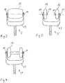
- FIGS. 2-4 show variants of the applicator according to the invention.
- a pneumatically operated pressure wave device on which the exemplary embodiment is based is well known, for which reference can be made to the prior art cited at the beginning. It has a base station with a pneumatic supply, an outgoing supply line and at the end of the supply line a mobile handpiece that can be handled by hand, which is referred to here as the device.
- the pneumatic supply is connected via the line and a corresponding switching valve to an acceleration tube, the left end of which is shown in the figure and numbered 1 in the figure.
- the pneumatic connection is located at the right end of the same tube 1, not shown, and in the tube 1, a projectile, not shown and filling the cross-section of the tube, can be moved, which can impact the right end face of a proximal applicator part 2 at the end of its movement distance.
- This proximal applicator part 2 has a largely conventional shape in comparison to the prior art and is supported with a radially enlarged flange and its distal shoulder side on an elastomer tube piece 3 which is deformable in the event of collisions and a movement of the proximal applicator part 2 can allow in the range over a millimeter. It is also responsible for the reset and decouples the blows from the device housing.
- this proximal applicator part 2 ends in a cylindrical pin which passes through a guide sleeve 4 and protrudes slightly beyond it on the distal side.
- this pin In conventional devices, the distal end face of this pin would be the contact surface of the applicator with the patient and the guide sleeve 4 in a (or as) unscrewable cap. You would have to remove the cap and do a partial disassembly before you can remove the applicator (in this case the proximal applicator part 2).
- the figure further shows that the left end face of the proximal applicator part 2 is in contact with the right end face of a distal applicator part 5.
- This distal applicator part 5 is based on the Figures 2-4 discussed in more detail. It is guided in a receptacle 6, namely positively, for. B hexagonal, and thus secured against rotation relative to this receiving piece 6.
- the receptacle 6, for its part must be held in the other housing in such a way that it is secured against rotation, for which purpose corresponding end faces pointing to the right in the figure or outwardly facing jacket surfaces can be coated in a friction-enhancing form or surface-structured.
- appropriate material combinations can be used, for example stainless steel on the applicator side and bronze, high-strength plastic (for example PEEK) or ceramic on the receiving side.
- the figure also shows that openings for form-locking balls 7 are provided in the receptacle 6 (above and below in the figure), which engage inward in corresponding outer grooves on the distal applicator part 5. These grooves are longer than necessary to the right in the figure, so that the entire applicator 5 and 6 can move to the left in one impact.
- the positive connection between the balls 7 and the associated grooves prevents the distal applicator part from falling out or shooting out of the housing. Rather, the distal applicator part can, for example, simply be pushed back into its drawn original position simply by being pressed onto the patient after an impact.
- a clamping sleeve 8 Radially outside the balls 7, a clamping sleeve 8 can be seen, which has an inner inclined surface at its left end. If this clamping sleeve 8 is moved to the right out of the position shown, the balls 7 can give way radially outwards and the distal applicator part 5 can simply be pulled out of the housing to the left. This displacement of the clamping sleeve 8 is ensured by manual (to the right) pushing in of an externally accessible housing part 9, a helical spring 10 pressing against it or ensuring the return movement, and this displaceable housing part 9 being displaceable in a further part 11 of the housing and by an O -Ring is guided. This part 11 encompasses and also holds the receiving piece 6 already mentioned.
- the balls 7 are not themselves subjected to force in the radial direction, but are displaced when the user pulls out the distal applicator part 5. Since there are only two (or in other cases, for example, three, four or six) balls for which separate grooves are provided, they also help to prevent rotation; However, the described polygonal positive-locking design of parts 5a on the outside and 6 on the inside is essential for securing against rotation.
- a projectile impact pushes the entire applicator to the left, resulting in a corresponding impact movement of the not shown distal end of the applicator (far left) against the patient's body, with the coupling of an actual pressure wave occurring in parallel, but in many cases is not essential at all.
- the pressure wave is generated in the proximal applicator part 2 and transmitted into the body via this and the distal applicator part 5.
- the proximal applicator part 2 automatically returns to the right as a result of the force exerted by the elastomer tube piece 3; for the distal applicator part 5, this follows from the pressure application on the patient's body.
- the distal applicator part 5 If the distal applicator part 5 is to be changed, the user pushes the displaceable housing part 9 to the right and thus also the clamping sleeve 4, so that the balls 7 can reach radially outwards. Incidentally, the openings in the receiving piece 6 for the balls 7 are too narrow radially on the inside, so that the balls cannot fall out.
- the housing part 9 When inserting another corresponding distal applicator part, the housing part 9 must be pushed to the right again in order to be able to displace the balls outwards. When the distal applicator part 5 is fully inserted, the housing part 9 can be released and the coupling locked.
- the Figures 2-4 show the configuration of the applicator or specifically the distal applicator part 5 in further details.
- the respective, here hexagonal rod for receiving in the receiving piece 6 with the grooves on the outside for the positive locking balls 7 can be seen.
- This rod leads to a fork-like widening 13, which in all three variants of the Figures 2-4 is identical and in their direction of impact (in the Figures 2-4 up and in Figure 1 ends or fork tines pointing to the left) have supports for bearing pins.
- FIG. 2 there is a continuous bearing pin defining the dash-dotted axis of rotation, the larger flattened ends 14 of which can be seen;
- Figure 4 there are two bearing pins with also flattened ends 14, one bearing pin per fork arm.
- Rotatable applicator parts namely a continuous convex barrel-shaped rotatable applicator part 15 in, are held on the bearing pins Figure 2 , two wheel-like applicator parts 16 in. each provided with a convex outer surface Figure 3 and a dumbbell-like rotatable applicator part 17 in Figure 4 , which is similar to the two applicator parts 16 Figure 3 , but is designed with a radially much smaller connection.
- the rotatability reduces the stress on the skin and facilitates the work of the therapist. It is also possible (but not mandatory) to hold the handpiece at an angle to the body surface (e.g. inclined about the respective axis of rotation so that the rotatable applicator part rolls in front of the handpiece), for example with an angle of rotation between 30% and 60%.
- a therapist can search for so-called trigger points along the body surface and carry out treatments with the combined effect of the pressure waves described, the actual impacts of the device and the massage effect.
- the front applicator parts can be used according to the Figures 2-4 interchange with each other, e.g. B. to with the examples from the Figures 3 and 4 to work along the spine so that the protruding areas of the rotatable applicator parts 16 and 17 roll on both sides of the spine.
- the parts can be made according to the Figures 2-4 can also be exchanged for conventional or differently shaped applicator parts.
- the fork and the hexagonal locating pin are made of metal, e.g. B. stainless steel or aluminum, which also applies to the bearing pins.
- the rotatable applicator parts 15-17 can consist of the materials mentioned above, for example also of plastic.
Landscapes
- Health & Medical Sciences (AREA)
- Epidemiology (AREA)
- Pain & Pain Management (AREA)
- Physical Education & Sports Medicine (AREA)
- Rehabilitation Therapy (AREA)
- Life Sciences & Earth Sciences (AREA)
- Animal Behavior & Ethology (AREA)
- General Health & Medical Sciences (AREA)
- Public Health (AREA)
- Veterinary Medicine (AREA)
- Percussion Or Vibration Massage (AREA)
- Surgical Instruments (AREA)
Description
- Die vorliegende Erfindung bezieht sich auf ein Gerät zur Behandlung des menschlichen oder tierischen Körpers durch Ausüben von Stößen auf die Körperoberfläche. Im Folgenden wird zur Vereinfachung vom Körper eines Patienten gesprochen, der bevorzugt menschlich ist.
- Im Stand der Technik sind verschiedene Geräte des beschriebenen Grundtyps bekannt. Die
DE 197 25 477 C beschreibt bspw. ein solches Gerät, bei dem durch die Kollision eines pneumatisch beschleunigten Schlagteils oder Projektils mit einem zunächst ruhenden Prallkörper oder Applikator eine Druckwelle ausgelöst wird, die dadurch in den Körper des Patienten eingekoppelt werden kann, dass eine Applikatorfrontfläche zum Zeitpunkt der Kollision auf den Patientenkörper aufgelegt wird. Dieser Gerätetyp leitet sich in seiner Entstehungsgeschichte von Lithotripsiegeräten ab, bei denen solche Druckwellen z. B. über eine lange stabförmige Sonde an der Frontfläche des Applikators auf einen Nierenstein oder Ähnliches übertragen werden können, um diesen zu desintegrieren. - Der Schwerpunkt bei der Darstellung liegt in jedem Fall auf der durch die Kollision erzeugten Druckwelle, die mehr oder weniger einer eigentlichen Stoßwelle ähneln soll, wie sie klassische, in der Regel fokussierende Lithotripsiegeräte z. B. mit piezoelektrischen oder elektromagnetischen Aktuatoren und Fokussierung auf einen Stein erzeugen. Solche Druckwellen können Anstiegsflanken mit einer Breite im Bereich weniger µs und einer Amplitude im niedrigen zweistelligen MPa-Bereich haben (z. B. 2 µs und 15 MPa gemessen 1 cm vor der Frontfläche). In dem zitierten Dokument wird hingegen betont, dass die physikalisch an sich unvermeidliche makroskopische Schwerpunktbewegung des Applikators möglichst klein gehalten werden soll, weil sie als störend angesehen wird.
- Als zweites Beispiel wird auf die
DE 20 2004 011 323 U und, mit sehr ähnlichem Inhalt, dieUS 2011/0054367 A1 verwiesen. Dort wird ein hinsichtlich des technischen Aufbaus ähnliches Gerät beschrieben, bei dem allerdings u. a. die elastische Aufhängung des Applikators im Gehäuse auf größere Schwerpunktsbewegungen des Applikators ("Hübe") ausgelegt ist. Dort wird betont, dass die therapeutische Wirkung durchaus auch, oder vorwiegend in den eigentlichen makroskopischen Stößen (also infolge des Hubes) gesehen werden kann, was auch von der Indikation abhängt. - Die vorliegende Erfindung richtet sich allgemein auf Geräte dieses Bautyps, und zwar sowohl hinsichtlich der Anwendung von Druckwellen als auch hinsichtlich der Anwendung "makroskopischer Stöße" des Applikator auf die Körperoberfläche.
- Die Merkmalskombination des Oberbegriffs des Anspruchs 1 ergibt sich aus der
DE 589 285 C mit einem Rollmassageapparat, der elektromagnetisch einen federnd aufgehängten Anker in eine Resonanzbewegung quer zur Gehäuselängsrichtung bringt. - Sie ergeben sich auch aus der
WO 2013/107 898 A1 mit einem pistolenartig aufgebauten Massagegerät, dessen Massagekopf periodische oszillierende Bewegungen mit asymmetrischer Schwingungsform, aber ohne zugrundeliegende Kollisionen, vollführt. - Schließlich ergeben sich diese Merkmale in Kombination auch aus der
US 2002/0107459 A1 mit einem weiteren vibrierenden Massagegerät, das austauschbare Massageköpfe unterschiedlicher Formen zeigt. - Schließlich wird verwiesen auf die
US 2002/0177795 A1 mit einem Gerät zur Erzeugung von kollisionsbedingten Stößen zur chiropraktischen Wirbelsäulenbehandlung. Dabei ist auf einen von diesen Stößen beaufschlagten Applikator ein stumpfkonischer Schaumstoffkopf aufgesetzt. - Dabei liegt der Erfindung die Aufgabe zugrunde, ein solches Gerät hinsichtlich weitergehender Anwendungsmöglichkeiten auf der Patientenkörperoberfläche weiterzubilden.
- Die Aufgabe wird gelöst durch ein Gerät nach Anspruch 1. Erfindungsgemäß ist dabei ein drehbares Applikatorteil vorgesehen. Es gibt also ein Drehlager, also insbesondere ein Wellenlager mit einem Achsstift aber z. B. auch ein Kugellager (Kugel geführt in Pfanne) oder ein komplexeres Lager wie z. B. ein Kardanlager. Über dieses Lager ist das drehbare Applikatorteil relativ zu dem restlichen Gerät um zumindest eine Drehachse drehbar, wobei diese Drehachse nicht parallel, also gewinkelt, zu der Richtung der von dem Gerät auszuführenden Stöße liegt. Vorzugsweise liegt die Drehachse senkrecht zur Stoßrichtung.
- Damit kann das Applikatorteil beim Aufdrücken auf die zu behandelnde Körperoberfläche abrollen. Dementsprechend soll das drehbare Applikatorteil in solcher Weise zugänglich liegen, dass das Gerät in der entsprechenden Weise auf den Körper aufgesetzt werden kann. In anderen Worten soll das drehbare Applikatorteil exponiert liegen. Bevorzugt ist eine Anordnung an dem distalen Ende eines entsprechenden Handstücks, das am anderen (proximalen) Ende über eine Leitung von einem Basisgerät versorgt ist.
- Die Erfinder haben nämlich festgestellt, dass es praktisch sein kann, den Applikator z. B. in Bezug auf die Stoßrichtung schräg auf die Patientenkörperoberfläche aufzusetzen und dann auf der Körperoberfläche zu bewegen. Insbesondere können dabei Gewebepartien unter der Haut parallel massiert und/oder gewissermaßen vor dem Gerät hergeschoben werden, wobei sie gleichzeitig mit den Stößen und (in einem von Fall zu Fall unterschiedlichen Maß) Druckwellen beaufschlagt werden. Die konventionell bekannten Geräte mit feststehenden und mehr oder weniger flachen Frontflächen der Applikatoren sind dazu relativ schlecht geeignet, weil sie auf der Hautoberfläche nur bei mehr oder weniger senkrechter Stellung des Geräts relativ zur Körperoberfläche gehalten werden können und in dieser Haltung schlecht verschoben werden können.
- Im Unterschied dazu lässt sich das erfindungsgemäße Gerät über die Oberfläche rollen und damit leicht und schonend bewegen, auch wenn ein gewisser Anpressdruck ausgeübt wird.
- Der Mechanismus zum Erzeugen der Stöße des Applikators ist in diesem Zusammenhang in unterschiedlichster Ausführung denkbar, insbesondere auch durch eine direkte Beaufschlagung des Applikators mittels eines elektromagnetischen Mechanismus oder auch eines Druckfluidpulses. Bevorzugt ist aber die aus den zitierten Dokumenten bereits bekannte Verwendung eines beschleunigten Projektils zur Kollision mit dem Applikator, womit relativ heftige und (im Sinn der Applikatorgeschwindigkeit) schnelle Stöße realisiert werden können und auch die gleichzeitige oder sogar schwerpunktmäßige Verwendung von Druckwellen möglich ist. Das Projektil wiederum lässt sich ebenfalls in unterschiedlicher Weise beschleunigen, insbesondere auch elektromagnetisch, wobei auch hier eine pneumatische Beaufschlagung des Projektils gemäß den zitierten Schriften bevorzugt ist.
- Der Begriff "Applikator" bezeichnet hier übrigens auch abgesehen von der Drehbarkeit nicht zwingend ein einstückiges Teil. Es ist denkbar und anwendungsabhängig auch bevorzugt, dass das Projektil z. B. auf ein erstes Teil schlägt, das den Stoß und/oder die Druckwelle auf ein zweites Applikatorteil überträgt, das seinerseits mit der Haut des Patienten in Kontakt steht. Im Stand der Technik ist auch gelegentlich von einem Zwischenstück zwischen Applikator und Projektil die Rede; hier wird dann von einem mehrteiligen Applikator gesprochen, wobei die beiden Applikatorteile fest verbunden sein können, aber nicht sein müssen.
- Wie eingangs bereits erwähnt, kann ein relativ großer Hub des Applikators durchaus gewünscht sein, wobei im vorliegenden Zusammenhang das Gerät vorzugsweise so ausgelegt ist, dass Hübe über 1 mm erreichbar sind, wie schon in der
US 2011/0054367 A1 ausgeführt. - Das drehbare Applikatorteil ist vorzugsweise rotationssymmetrisch in Bezug auf die Drehachse als Symmetrieachse, um sich besonders gut abrollen zu lassen. Diese Rotationssymmetrie betrifft dabei die grobe Gestalt, also sozusagen eine Einhüllende, und steht oberflächlichen Strukturen, etwa Rillen zu Massagezwecken, nicht entgegen. Das drehbare Applikatorteil ist ferner vorzugsweise spiegelsymmetrisch, und zwar in Bezug auf eine Symmetrieebene senkrecht zur Drehachse. Das erleichtert im Regelfall die Anwendung und erlaubt bei geeigneter Positionierung des drehbaren Applikatorteils relativ zu dem restlichen Gerät oder Handstück auch eine entsprechende Benutzung "von zwei Seiten".
- Die drehbare Lagerung erfolgt vorzugsweise beidseits, insbesondere mit einem durchgehenden Lagerstift. Eine solche Konstruktion ist einfach und gleichzeitig stabil.
- Ferner sind abgerundete Kanten bevorzugt, und zwar soweit Berührungsmöglichkeiten mit der zu behandelnden Körperoberfläche bestehen, also außenseitig. Nicht betroffen sind also z. B. Kanten am Übergang zu einer zentrischen Bohrung für den Lagerstift.
- Eine bevorzugte Form ist eine Tonnenform, also eine im Wesentlichen zylindrische Form mit allerdings verdicktem Mittenbereich, also einem konvexen Außenprofil bezogen auf eine die Drehachse enthaltende Schnittebene. Hierzu wird auf das erste Ausführungsbeispiel verwiesen. Mit einer solchen Form lassen sich einerseits großflächige Behandlungen erreichen, kann aber andererseits im bezüglich der Drehachse mittleren Bereich ein etwas höherer Anpressdruck und damit eine konzentrierte Wirkung erzielt werden.
- Eine andere bevorzugt Form weist mindestens zwei in Bezug auf die Drehachse radial vorstehende Bereiche auf, die jeweils zum Kontakt mit der Körperoberfläche ausgelegt sind. Hierzu wird auf das zweite Ausführungsbeispiel verwiesen. Eine solche Form kann z. B. günstig sein, um beidseits neben einem nicht zu behandelnden oder zu schonenden Bereich entlang fahren zu können, bspw. rechts und links neben der Wirbelsäule eines Patienten.
- Vorbekannte Applikatoren bestanden im Regelfall aus rostfreiem Stahl. Im vorliegenden Fall kommen grundsätzlich auch Metalle, so auch rostfreier Stahl, in Betracht. Daneben sind als metallische Materialien Aluminium und Titan zu nennen, wobei beide eine relativ geringe Massendichte haben und damit relativ leichte Applikatoren ermöglichen. Das kann den Vorteil haben, bei gegebener Geometrie eine stärkere Beschleunigung und damit auch größere Hubauslenkung des Applikators zu ermöglichen, was im vorliegenden Fall gewünscht sein kann. Titan zeichnet sich zudem durch eine besonders hohe mechanische Belastbarkeit aus, eignet sich also besonders für Anwendungen mit vergleichsweise hohen Projektilgeschwindigkeiten und/oder Projektilmassen. Da Titan außerdem eine besonders gute physiologische Verträglichkeit auszeichnet, kann es als Applikatormaterial auch unabhängig von der Belastbarkeit von Vorteil sein.
- In Betracht kommen, insbesondere für das drehbare Applikatorteil, ferner Keramiken, vgl. Anmeldenummer
08 003 840.9 EP 2 095 843 , und Kunststoffe. Im Vergleich zu rostfreiem Stahl weisen auch diese den Vorteil geringer Massendichte auf. Sie haben ferner eine geringere Wärmeleitfähigkeit als Metalle, sodass der Patient den Applikator subjektiv als wärmer empfindet. Das gilt vor allem für Kunststoffe, wieder insbesondere für das drehbaren Teil. Kunststoffe kommen insbesondere auch dann in Betracht, wenn auf die Einkopplung einer Druckwelle geringerer Wert gelegt wird, weil, jedenfalls bei einer größeren Stärke des Kunststoffs, im Vergleich zu den vorgenannten Materialien etwas größere Wellenleitungsverluste zu erwarten sind. Gleiche Argumente gelten für Holz. - Nach einer weiteren Ausgestaltung ist der Applikator in einer lösbaren Kupplung gehalten, sodass zumindest ein distales Applikatorteil (mit dem drehbaren Applikatorteil) aus dem Gerät nach vorn herausgezogen werden kann. Zur Klarstellung: Die Begriffe "proximal" und "distal" werden hier aus der Perspektive eines Benutzers des Geräts gebraucht; in anderen Worten bedeutet "distal" eine dem Patienten zugewandte Position und "proximal" eine dazu entgegengesetzte. Im gleichen Sinn wird als "vorn" die distale Richtung bezeichnet, also auf den Patienten zu.
- Die Erfinder haben festgestellt, dass die Optimierung der Applikatoreigenschaften im Hinblick auf bestimmte Behandlungen, bspw. der Wechsel zwischen einem erfindungsgemäßen Applikator und einem konventionellen oder zwischen verschiedenen Applikatoren mit drehbaren Applikatorteilen, vorteilhafterweise mit im Übrigen unverändertem Gerät von Fall zu Fall vorgenommen werden kann.
- Ein Applikator in diesem Sinn kann mehrteilig aufgebaut sein, wobei die Entnehmbarkeit primär einen distalen Teil betrifft. Dieser distale Teil des Applikators kann dann gegen andere entsprechende distale Applikatorteile getauscht werden, zum Beispiel weil das Applikatorteil nur eine begrenzte Lebensdauer hat, weil es gereinigt oder sterilisiert werden soll oder weil ein anderer Typ dieses distalen Applikatorteils (oder des gesamten Applikators) verwendet werden soll. Insbesondere ist es möglich, in ihrem distalen Teil unterschiedlich geformte drehbare Applikatorteile, möglicherweise auch aus verschiedenen Materialien, einzusetzen.
- Der Austausch erfolgt dabei sehr einfach und schnell, vorzugsweise völlig werkzeuglos und ebenfalls vorzugsweise ohne Abbauen eines weiteren Geräteteils, etwa eine Aufschraubkappe bei konventionellen Geräten dieses Typs. Bei diesen konventionellen Geräten war der Applikator in der Regel einteilig und innerhalb des Gerätegehäuses etwas dicker (senkrecht zur Stoßrichtung) als eine vordere Öffnung. Ein Ausbau war daher möglich, aber nur nach Teilzerlegung des Gehäuses, nämlich Abschrauben einer Schraubkappe und nicht durch Lösen einer für den Applikatorwechsel vorgesehenen Kupplung.
- Eine bevorzugte Ausführungsform sieht eine Verdrehsicherung des Applikators in dem Gerät vor (nicht zwingend in der Kupplung). Dementsprechend kann zum Beispiel die Kupplung selbst eine Verdrehsicherheit herstellen oder durch Einschieben eines entsprechend gestalteten Bereichs des Applikators in eine entsprechende Aufnahme eine Verdrehsicherheit hergestellt werden, besonders bevorzugterweise durch einen Mehrkantstift auf der Applikatorseite und eine dazu passende Aufnahme auf der Geräteseite, etwa durch einen hexagonalen Formschluss. Dies beinhaltet Varianten, bei denen die Verdrehsicherung erst durch einen axial gerichteten Druck entsteht und ohne diesen Andruck eine Drehbarkeit gegeben ist. Die Verdrehsicherung betrifft dabei bevorzugt zumindest auch eine von der (die Bewegung in Stoßrichtung betreffende) Kupplung selbst unabhängige Aufnahme, um die Möglichkeiten zur Kraftaufnahme zu verbessern. Zur Veranschaulichung wird auf das Ausführungsbeispiel verwiesen.
- Die Kupplung kann vorzugsweise ebenfalls mit einem Formschluss arbeiten, der nicht zwingend mit dem Formschluss für die Verdrehsicherung übereinstimmen muss. Insbesondere kann eine Klemmhülse vorgesehen sein, die (vorzugsweise in Stoßrichtung) verschiebbar ist und dabei zumindest ein Formschlusselement in eine entsprechende Aufnahme an dem Applikator hereindrückt bzw. beim Lösen freigibt. Insbesondere kann ein Gehäuseteil des Geräts gegen eine Federkraft verschiebbar sein und dabei die Klemmhülse aufweisen oder mitverschieben. Als Formschlusselement kommt eine Kugel in Betracht, wobei vorzugsweise mindestens zwei Kugeln vorgesehen sind. Die Kugeln oder andere Formschlusselemente können durch eine schräge Fläche an einer Innenseite der Klemmhülse beaufschlagt werden.
- Im Folgenden wird die Erfindung anhand eines Ausführungsbeispiels beschrieben, wobei die Offenbarung im Ausführungsbeispiel und auch im vorstehenden Text nicht auf die jeweils dargestellten Merkmalskombinationen beschränkt sein soll, sondern einzelne Merkmale auch in anderem Zusammenhang oder für sich wichtig sein können.
-
Figur 1 zeigt einen Längsschnitt durch einen vorderen Gehäuseteil eines erfindungsgemäßen Geräts mit einer Applikatorkupplung. - Die
Figuren 2-4 zeigen erfindungsgemäße Varianten des Applikators. - Der dem Ausführungsbeispiel zugrunde liegende Typ eines pneumatisch betriebenen Druckwellengeräts ist hinlänglich bekannt, wozu auf den eingangs zitierten Stand der Technik verwiesen werden kann. Er weist eine Basisstation mit einer Pneumatikversorgung, eine davon ausgehende Versorgungsleitung und am Ende der Versorgungsleitung ein mobiles und mit der Hand handhabbares Handstück auf, das hier als das Gerät bezeichnet wird. Die Pneumatikversorgung ist über die Leitung und ein entsprechendes Schaltventil an ein Beschleunigungsrohr angeschlossen, dessen in der Darstellung der Figur linkes Ende in der Figur eingezeichnet und mit 1 beziffert ist. Der Pneumatikanschluss findet sich am nicht dargestellten rechten Ende desselben Rohres 1 und in dem Rohr 1 ist ein nicht dargestelltes und den Querschnitt des Rohres ausfüllendes Projektil bewegbar, das am Ende seiner Bewegungsstrecke auf die rechte Stirnfläche eines proximalen Applikatorteils 2 aufprallen kann.
- Dieses proximale Applikatorteil 2 hat eine im Vergleich zum Stand der Technik weitgehend konventionelle Form und stützt sich mit einem radial vergrößerten Flansch und dessen distaler Schulterseite an einem Elastomerschlauchstück 3 ab, das bei den Kollisionen verformbar ist und eine Bewegung des proximalen Applikatorteils 2 im Bereich über einem Millimeter zulassen kann. Es ist ferner für die Rückstellung verantwortlich und entkoppelt die Schläge vom Gerätegehäuse. An der distalen Seite läuft dieses proximale Applikatorteil 2 in einem zylindrischen Stift aus, der eine Führungsmanschette 4 durchsetzt und zur distalen Seite etwas darüber hinausragt. Bei konventionellen Geräten wäre die distale Stirnfläche dieses Stifts die Kontaktfläche des Applikators zum Patienten und die Führungsmanschette 4 in einer (oder als) abschraubbaren Kappe realisiert. Man müsste also die Kappe abnehmen und damit eine Teilzerlegung vornehmen, bevor man den Applikator (in diesem Fall das proximale Applikatorteil 2) entnehmen kann.
- Die Figur zeigt ferner, dass sich die linke Stirnfläche des proximalen Applikatorteils 2 in Kontakt mit der rechten Stirnfläche eines distalen Applikatorteils 5 befindet. Auf dieses distale Applikatorteil 5 wird anhand der
Figuren 2-4 näher eingegangen. Es ist in einem Aufnahmestück 6 geführt, und zwar formschlüssig, z. B hexagonal, und damit gegenüber diesem Aufnahmestück 6 gegen Verdrehung gesichert. Das Aufnahmestück 6 seinerseits muss entsprechend fest verdrehgesichert im übrigen Gehäuse gehalten sein, wozu entsprechende in der Figur nach rechts weisende Stirnflächen oder nach außen weisende Mantelflächen in reibungssteigernder Form beschichtet oder oberflächenstrukturiert sein können. Das kann auch so geschehen, dass ohne axialen Andruck noch eine Verdrehbarkeit gewährleistet ist, etwa um den Applikator nach Wunsch auszurichten, und nach Auflegen und Andrücken auf den Patientenkörper, also mit axialem Andruck, ein ausreichender Reibungsschluss zur Verdrehsicherung hergestellt wird. Um ein Fressen zwischen dem distalen Applikatorteil 5 und dem Aufnahmestück 6 zu verhindern, können entsprechende Materialpaarungen verwendet werden, zum Beispiel applikatorseitig rostfreier Edelstahl und aufnahmeseitig Bronze, hochfester Kunststoff (zum Beispiel PEEK) oder Keramik. - Die Figur zeigt ferner, dass in dem Aufnahmestück 6 (in der Figur oben und unten) Öffnungen für Formschlusskugeln 7 vorgesehen sind, die nach innen in entsprechende außenseitige Nuten an dem distalen Applikatorteil 5 eingreifen. Diese Nuten sind in der Figur nach rechts länger als nötig, sodass sich der gesamte Applikator 5 und 6 bei einem Stoß nach links bewegen kann. Andererseits verhindert der Formschluss zwischen den Kugeln 7 und den dazugehörenden Nuten ein Herausfallen oder -schießen des distalen Applikatorteils aus dem Gehäuse. Das distale Applikatorteil kann vielmehr zum Beispiel einfach durch Aufdrücken auf dem Patienten nach einem Stoß wieder in seine gezeichnete Ursprungslage zurückgeschoben werden.
- Radial außerhalb der Kugeln 7 erkennt man eine Klemmhülse 8, die ersichtlich an ihrem linken Ende eine innere Schrägfläche aufweist. Wenn diese Klemmhülse 8 aus der gezeichneten Position heraus nach rechts verschoben wird, können die Kugeln 7 radial nach außen weichen und kann das distale Applikatorteil 5 insgesamt einfach nach links aus dem Gehäuse herausgezogen werden. Für dieses Verschieben der Klemmhülse 8 sorgt ein händisches (nach rechts) Hineindrücken eines von außen zugänglichen Gehäuseteils 9, wobei eine Schraubenfeder 10 dagegen drückt bzw. für die Rückführbewegung sorgt und dieses verschiebbare Gehäuseteil 9 in einem weiteren Teil 11 des Gehäuses verschiebbar und durch einen O-Ring gehemmt geführt ist. Dieses Teil 11 umgreift und hält auch das bereits erwähnte Aufnahmestück 6.
- Die Kugeln 7 sind übrigens in radialer Richtung nicht kraftbeaufschlagt an sich, sondern werden verdrängt, wenn der Benutzer das distale Applikatorteil 5 herauszieht. Da es sich nur um zwei (oder in anderen Fällen um zum Beispiel drei, vier oder sechs) Kugeln handelt, für die jeweils eigene Nuten vorgesehen sind, tragen sie auch zur Verdrehsicherung bei; wesentlich für die Verdrehsicherung ist aber die beschriebene Mehrkant-Formschluss-Ausführung der Teile 5a außen und 6 innen.
- In der Figur links von dem verschiebbaren und zur Betätigung der Kupplung dienenden Gehäuseteil 9 findet sich noch eine Sicherungsmutter 12, die auf dem Aufnahmeteil 6 aufgeschraubt und gegenüber diesem über einen O-Ring und gegenüber dem Teil 5 über einen Elastomerflachring abgedichtet ist. Dabei ist die Anlage zwischen dem Elastomerflachring (an dessen Innenrand) und dem hier hexagonalen ersten Stück des distalen Applikatorteils 5 gleitfähig.
- Insgesamt erkennt man, dass ein Projektilstoß den gesamten Applikator nach links versetzt und dabei eine entsprechende Stoßbewegung des nicht gezeichneten distalsten Endes des Applikators (ganz links) gegen den Patientenkörper zur Folge hat, wobei die Einkopplung einer eigentlichen Druckwelle parallel auftreten wird, aber in vielen Fällen gar nicht wesentlich ist. Die Druckwelle wird dabei übrigens in dem proximalen Applikatorteil 2 erzeugt und über dieses und das distale Applikatorteil 5 in den Körper übertragen. Nach dem Stoß kehrt das proximale Applikatorteil 2 infolge der Kraftbeaufschlagung durch das Elastomerschlauchstück 3 selbsttätig nach rechts zurück; für das distale Applikatorteil 5 folgt dies aus der Druckauflage auf den Patientenkörper.
- Wenn das distale Applikatorteil 5 gewechselt werden soll, schiebt der Benutzer das verschiebbare Gehäuseteil 9 nach rechts und damit die Klemmhülse 4 ebenfalls, sodass die Kugeln 7 radial nach außen gelangen können. Dabei sind übrigens die Öffnungen in dem Aufnahmestück 6 für die Kugeln 7 radial innen zu eng, sodass die Kugeln nicht herausfallen können. Beim Wiedereinsetzen eines anderen entsprechenden distalen Applikatorteils muss wieder das Gehäuseteil 9 nach rechts geschoben werden, um die Kugeln nach außen verdrängen zu können. Wenn das distale Applikatorteil 5 vollständig eingesetzt ist, kann man das Gehäuseteil 9 loslassen und verriegelt die Kupplung.
- Die
Figuren 2-4 zeigen die Ausgestaltung des Applikators bzw. konkret des distalen Applikatorteils 5 in weiteren Einzelheiten. Zunächst erkennt man in allen Figuren nach unten weisend den jeweiligen, hier hexagonalen Stab zur Aufnahme in dem Aufnahmestück 6 mit den außenseitigen Nuten für die Formschlusskugeln 7. Dieser Stab führt zu einer gabelartigen Verbreiterung 13, die in allen drei Varianten derFiguren 2-4 identisch ist und an ihren in Stoßrichtung (in denFiguren 2-4 nach oben und inFigur 1 nach links) weisenden Enden bzw. Gabelzinken Aufnahmen für Lagerstifte trägt. - Bei der Variante aus
Figur 2 ist ein durchgängiger und die strichpunktierte Drehachse definierender Lagerstift vorgesehen, dessen größere abgeflachte Enden 14 erkennbar sind; das Gleiche gilt fürFigur 4 . InFigur 3 sind es zwei Lagerstifte mit ebenfalls abgeflachten Enden 14, und zwar jeweils ein Lagerstift pro Gabelarm. An den Lagerstiften gehalten sind drehbare Applikatorteile, und zwar ein durchgehendes konvex-tonnenförmiges drehbares Applikatorteil 15 inFigur 2 , zwei jeweils radartig und mit konvexer Außenfläche versehene drehbare Applikatorteile 16 inFigur 3 und ein hantelartiges drehbares Applikatorteil 17 inFigur 4 , das ähnlich den beiden Applikatorteilen 16 ausFigur 3 , aber mit einer radial viel kleineren Verbindung ausgestaltet ist. - Nach dem Einsetzen in die Aufnahmekupplung aus
Figur 1 übertragen sich die Stöße infolge der beschriebenen Kollisionen über die hexagonalen Stifte und die Gabeln 13 sowie die Lagerstifte auf die drehbaren Applikatorteile 15-17 und können von diesen in einen Patientenkörper eingekoppelt werden. Dazu wird das sich inFigur 1 rechts an den gezeichneten Bereich anschließende Handstück des Geräts (in einer weiteren Ausgestaltung gemäß dem eingangs zitierten Stand der Technik) so mit der Hand gehalten, dass die drehbaren Applikatorteile 15-17 auf der Körperoberfläche aufliegen. Dazu können die drehbaren Applikatorteile 15-17, z. B. zur Behandlung von Faszien, entlang der Haut geschoben werden und die darunterliegenden Faszien quasi vor sich herschieben, wobei die Drehbarkeit die Belastung für die Haut reduziert und die Tätigkeit des Therapeuten erleichtert. Dabei ist auch (aber nicht zwingend) eine schräge Haltung des Handstücks zur Körperoberfläche möglich (z. B. um die jeweilige Drehachse geneigt, sodass beim Schieben das drehbare Applikatorteil vor dem Handstück rollt), etwa mit Drehwinkel zwischen 30 % und 60 %. Ein Therapeut kann in dieser Form entlang der Körperoberfläche nach sogenannten Triggerpunkten suchen und Behandlungen mit der kombinierten Wirkung der beschriebenen Druckwellen, der eigentlichen Stöße des Geräts und der Massagewirkung ausführen. - Für verschiedene Anwirkungen lassen sich die vorderen Applikatorteile gemäß den
Figuren 2-4 untereinander vertauschen, z. B. um mit den Beispielen aus denFiguren 3 und 4 entlang der Wirbelsäule so zu arbeiten, dass die vorstehenden Bereiche der drehbaren Applikatorteile 16 und 17 beidseits der Wirbelsäule abrollen. Mit Hilfe der verschiedenen Aufnahmekupplungen können die Teile gemäß denFiguren 2-4 auch gegen konventionelle oder anders geformte Applikatorteile ausgetauscht werden. - Bei den Ausführungsbeispielen bestehen die Gabel und der hexagonale Aufnahmestift aus Metall, z. B. rostfreiem Stahl oder Aluminium, was auch für die Lagerstifte gilt. Die drehbaren Applikatorteile 15-17 können aus den im Übrigen erwähnten Materialien, bspw. auch aus Kunststoff, bestehen.
Claims (12)
- Gerät zur Behandlung des menschlichen oder tierischen Körpers mit- einem Applikator (2, 5, 5', 5") zum Auflegen auf den Körper von au-βen,- einem Gehäuse (9, 11, 12), in dem der Applikator (2, 5, 5', 5") gehalten ist, und- einem Mechanismus zum Erzeugen von Stößen des Applikators (2, 5, 5', 5") relativ zu dem Gehäuse (9, 11, 12) in einer Stoßrichtung, sodass die Stöße bei dem Auflegen in den Körper eingekoppelt werden können,wobei der Applikator (2, 5, 5', 5") ein Drehlager (14) aufweist, welches ein auf dem zu behandelnden Körper anzuordnendes drehbares Applikatorteil (15, 16, 17) des Applikators (2, 5, 5', 5") drehbar hält, und
eine Drehung des drehbaren Applikatorteils (15, 16, 17) um eine zu der Stoßrichtung gewinkelte Drehachse möglich ist,
dadurch gekennzeichnet, dass der Mechanismus zum Erzeugen der Stöße ein Projektil und eine pneumatische Einrichtung zum Beschleunigen des Projektils in solcher Weise aufweist, dass das Projektil auf den Applikator (2, 5, 5', 5") schlägt und dadurch den Stoß erzeugt,
und wobei der Applikator (2, 5, 5', 5") in dem Gerät durch einen Formschluss verdrehsicher gehalten wird, und zwar bezüglich Rotationen um eine zur Stoßrichtung parallele Achse. - Gerät nach Anspruch 1, bei dem die Drehachse senkrecht zu der Stoßrichtung liegt.
- Gerät nach Anspruch 1 oder 2, bei dem das drehbare Applikatorteil (15, 16, 17) in Bezug auf die Drehachse rotationssymmetrisch ist.
- Gerät nach einem der vorstehenden Ansprüche, bei dem das drehbare Applikatorteil (15, 16, 17) in Bezug auf eine zu der Drehachse senkrechte Ebene spiegelsymmetrisch ist.
- Gerät nach einem der vorstehenden Ansprüche, bei dem das drehbare Applikatorteil (15, 17) an zwei entgegengesetzten Seiten drehbar gehalten ist, insbesondere von einer die Drehachse definierenden Achsstange durchsetzt ist.
- Gerät nach einem der vorstehenden Ansprüche, bei dem das drehbare Applikatorteil (15, 16, 17) außenseitig abgerundete Kanten mit einem Krümmungsradius von mindestens 1mm aufweist.
- Gerät nach Anspruch 3, auch in Verbindung mit einem der Ansprüche 4-6, bei dem das drehbare Applikatorteil (15) eine zylindrische Tonnenform mit einem konvexen Außenprofil in einer die Drehachse enthaltenden Schnittebene aufweist.
- Gerät nach einem der Ansprüche 1-6, bei dem das drehbare Applikatorteil (17) mindestens zwei in Bezug auf die Drehachse radial vorstehende und zum Kontakt mit dem zu behandelnden Körper ausgelegte Bereiche aufweist.
- Gerät nach einem der vorstehenden Ansprüche, bei dem der Applikator (2, 5, 5', 5") in seinem zum Auflegen ausgelegten drehbaren Teil (15, 16, 17) besteht aus Metall, insbesondere Aluminium oder Titan, Kunststoff, Keramik oder Holz.
- Gerät nach einem der vorstehenden Ansprüche, das ausgelegt ist für einen Hub des Stoßes in der Stoßrichtung relativ zu dem Gehäuse (9, 11, 12) von mindestens 1 mm.
- Gerät nach einem der vorstehenden Ansprüche, bei dem der Applikator (2, 5, 5', 5") in dem Gehäuse (9, 11, 12) in einer Kupplung (7, 8, 9, 10) gehalten ist, wobei zumindest ein distales Applikatorteil (5) mit dem drehbaren Applikatorteil (15, 16, 17) nach Lösen der Kupplung (7, 8, 9, 10) in distaler Richtung aus dem Gehäuse (9, 11, 12) herausziehbar ist.
- Gerät nach einem der vorstehenden Ansprüche, bei dem der Applikator (2, 5, 5', 5") zumindest zweiteilig ist, wobei ein distales Applikatorteil (5, 5', 5") nach Lösen einer Kupplung (7, 8, 9, 10) herausziehbar ist und ein proximales Applikatorteil (2) in dem Gehäuse verbleibt und wobei das proximale Applikatorteil (2) den Stoß auf das distale Applikatorteil (5, 5', 5") überträgt.
Priority Applications (1)
| Application Number | Priority Date | Filing Date | Title |
|---|---|---|---|
| EP15178506.0A EP3124004B1 (de) | 2015-07-27 | 2015-07-27 | Gerät zur behandlung des menschlichen oder tierischen körpers mit mechanischen stössen |
Applications Claiming Priority (1)
| Application Number | Priority Date | Filing Date | Title |
|---|---|---|---|
| EP15178506.0A EP3124004B1 (de) | 2015-07-27 | 2015-07-27 | Gerät zur behandlung des menschlichen oder tierischen körpers mit mechanischen stössen |
Publications (2)
| Publication Number | Publication Date |
|---|---|
| EP3124004A1 EP3124004A1 (de) | 2017-02-01 |
| EP3124004B1 true EP3124004B1 (de) | 2020-03-18 |
Family
ID=53762014
Family Applications (1)
| Application Number | Title | Priority Date | Filing Date |
|---|---|---|---|
| EP15178506.0A Active EP3124004B1 (de) | 2015-07-27 | 2015-07-27 | Gerät zur behandlung des menschlichen oder tierischen körpers mit mechanischen stössen |
Country Status (1)
| Country | Link |
|---|---|
| EP (1) | EP3124004B1 (de) |
Families Citing this family (3)
| Publication number | Priority date | Publication date | Assignee | Title |
|---|---|---|---|---|
| US11484724B2 (en) | 2015-09-30 | 2022-11-01 | Btl Medical Solutions A.S. | Methods and devices for tissue treatment using mechanical stimulation and electromagnetic field |
| US12220380B2 (en) | 2015-09-30 | 2025-02-11 | Btl Medical Solutions A.S. | Methods and devices for tissue treatment using mechanical stimulation and electromagnetic field |
| EP3388003B1 (de) * | 2017-04-12 | 2020-07-22 | Storz Medical Ag | Druckwellengerät |
Citations (2)
| Publication number | Priority date | Publication date | Assignee | Title |
|---|---|---|---|---|
| EP2181730A1 (de) * | 2008-10-31 | 2010-05-05 | Ferton Holding SA | Instrument zur Behandlung von biologischem Gewebe, sowie Verfahren zum Erzeugen von stoßwellenartigen Druckwellen in einem solchen Instrument |
| DE202010007860U1 (de) * | 2010-06-11 | 2011-09-27 | Storz Medical Ag | Druckwellengerät mit pneumatischem Antrieb |
Family Cites Families (10)
| Publication number | Priority date | Publication date | Assignee | Title |
|---|---|---|---|---|
| DE589285C (de) * | 1930-03-22 | 1934-03-24 | Max Schneidinger | Vibrations- und Rollmassageapparat |
| DE29512015U1 (de) * | 1995-07-25 | 1995-09-14 | Dr. Frenkel GmbH Geräte mit natürlicher Wirkweise, 72514 Inzigkofen | Massageroller als Zusatzteil für ein Handmassagegerät |
| DE19725477C2 (de) | 1997-06-17 | 1999-10-21 | Ferton Holding | Medizinisches Instrument zur Behandlung von biologischem Gewebe |
| US20020107459A1 (en) * | 2001-02-05 | 2002-08-08 | Chang Horng Jiun | Massage device having eccentric vibrating mechanism |
| US6503211B2 (en) * | 2001-05-25 | 2003-01-07 | Bruce A. Frye | Pneumatic spinal and extremity manipulator |
| US6758826B2 (en) * | 2001-07-03 | 2004-07-06 | Water Pik, Inc. | Vibrating personal massager |
| DE202004011323U1 (de) | 2004-07-09 | 2005-09-22 | Storz Medical Ag | Instrument zum Applizieren von Vibrationen auf dem menschlichen Körper |
| US8500665B2 (en) | 2004-07-09 | 2013-08-06 | Storz Medical Ag | Instrument for applying vibrations to the human body |
| ATE489995T1 (de) | 2008-02-29 | 2010-12-15 | Storz Medical Ag | Vorrichtung zur behandlung biologischer körpersubstanzen mit mechanischen druckwellen |
| BE1020090A5 (fr) * | 2012-01-20 | 2013-04-02 | M D Concept | Appareil pour le traitement extracorporel par ondes de choc. |
-
2015
- 2015-07-27 EP EP15178506.0A patent/EP3124004B1/de active Active
Patent Citations (2)
| Publication number | Priority date | Publication date | Assignee | Title |
|---|---|---|---|---|
| EP2181730A1 (de) * | 2008-10-31 | 2010-05-05 | Ferton Holding SA | Instrument zur Behandlung von biologischem Gewebe, sowie Verfahren zum Erzeugen von stoßwellenartigen Druckwellen in einem solchen Instrument |
| DE202010007860U1 (de) * | 2010-06-11 | 2011-09-27 | Storz Medical Ag | Druckwellengerät mit pneumatischem Antrieb |
Also Published As
| Publication number | Publication date |
|---|---|
| EP3124004A1 (de) | 2017-02-01 |
Similar Documents
| Publication | Publication Date | Title |
|---|---|---|
| DE202015005257U1 (de) | Gerät zur Behandlung des menschlichen oder tierischen Körpers mit mechanischen Stößen | |
| EP3388003B1 (de) | Druckwellengerät | |
| EP3000420B1 (de) | Gerät zur behandlung des menschlichen oder tierischen körpers mit mechanischen stössen | |
| EP2497432B1 (de) | Medizinisches Einstechwerkzeug | |
| EP2996585B1 (de) | Chirurgisches instrument | |
| EP1922004B1 (de) | Schraubendreher für knochenschrauben | |
| DE102012106336A1 (de) | Knochenschraube und Knochenfixierungssystem | |
| DE202011101571U1 (de) | Schalldämpfungshülse zum Aufsetzen auf ein Druckwellengerät | |
| EP3124004B1 (de) | Gerät zur behandlung des menschlichen oder tierischen körpers mit mechanischen stössen | |
| EP0928602A2 (de) | Scherwerkzeug für Implantate | |
| EP2086429B1 (de) | Medizinisches handgerät | |
| EP3000418B1 (de) | Gerät zur Behandlung des menschlichen oder tierischen Körpers mit mechanischen Stößen | |
| EP1099900B1 (de) | Gelenkstativ | |
| DE102014113634A1 (de) | Modulares chirurgisches Instrument der Ein-Wege-Bauart | |
| EP3250133B1 (de) | Schaftinstrument für chirurgische zwecke | |
| DE202004001504U1 (de) | Vorrichtung zum Einspannen von Knochenfixationsmitteln | |
| EP1954203B1 (de) | Chirurgisches führungsinstrument | |
| DE19949385C2 (de) | Vorrichtung zum Knochenverdichten für zahnärztlichimplantologische Zwecke | |
| DE202014010958U1 (de) | Werkzeug zum Aufbringen kleiner Schlagimpulse | |
| DE102014107173A1 (de) | Werkzeug und Verfahren zum Aufbringen kleiner Schlagimpulse | |
| DE202014007692U1 (de) | Gerät zur Behandlung des menschlichen oder tierischen Körpers mit mechanischen Stößen | |
| EP3494912A1 (de) | Vorrichtung zum lösen von, insbesondere kaltverschweissten, schrauben in der orthopädie sowie werkzeugeinsatz | |
| DE202017001951U1 (de) | Druckwellengerät | |
| EP3000419B1 (de) | Gerät zur Behandlung des menschlichen oder tierischen Körpers mit mechanischen Stößen | |
| DE202007000427U1 (de) | Chirurgischer Haltegriff und chirurgisches Instrument |
Legal Events
| Date | Code | Title | Description |
|---|---|---|---|
| PUAI | Public reference made under article 153(3) epc to a published international application that has entered the european phase |
Free format text: ORIGINAL CODE: 0009012 |
|
| STAA | Information on the status of an ep patent application or granted ep patent |
Free format text: STATUS: REQUEST FOR EXAMINATION WAS MADE |
|
| 17P | Request for examination filed |
Effective date: 20160415 |
|
| AK | Designated contracting states |
Kind code of ref document: A1 Designated state(s): AL AT BE BG CH CY CZ DE DK EE ES FI FR GB GR HR HU IE IS IT LI LT LU LV MC MK MT NL NO PL PT RO RS SE SI SK SM TR |
|
| AX | Request for extension of the european patent |
Extension state: BA ME |
|
| RBV | Designated contracting states (corrected) |
Designated state(s): AL AT BE BG CH CY CZ DE DK EE ES FI FR GB GR HR HU IE IS IT LI LT LU LV MC MK MT NL NO PL PT RO RS SE SI SK SM TR |
|
| STAA | Information on the status of an ep patent application or granted ep patent |
Free format text: STATUS: EXAMINATION IS IN PROGRESS |
|
| 17Q | First examination report despatched |
Effective date: 20171129 |
|
| GRAP | Despatch of communication of intention to grant a patent |
Free format text: ORIGINAL CODE: EPIDOSNIGR1 |
|
| STAA | Information on the status of an ep patent application or granted ep patent |
Free format text: STATUS: GRANT OF PATENT IS INTENDED |
|
| INTG | Intention to grant announced |
Effective date: 20191024 |
|
| GRAS | Grant fee paid |
Free format text: ORIGINAL CODE: EPIDOSNIGR3 |
|
| GRAA | (expected) grant |
Free format text: ORIGINAL CODE: 0009210 |
|
| STAA | Information on the status of an ep patent application or granted ep patent |
Free format text: STATUS: THE PATENT HAS BEEN GRANTED |
|
| AK | Designated contracting states |
Kind code of ref document: B1 Designated state(s): AL AT BE BG CH CY CZ DE DK EE ES FI FR GB GR HR HU IE IS IT LI LT LU LV MC MK MT NL NO PL PT RO RS SE SI SK SM TR |
|
| REG | Reference to a national code |
Ref country code: GB Ref legal event code: FG4D Free format text: NOT ENGLISH |
|
| REG | Reference to a national code |
Ref country code: DE Ref legal event code: R096 Ref document number: 502015012023 Country of ref document: DE |
|
| REG | Reference to a national code |
Ref country code: AT Ref legal event code: REF Ref document number: 1245075 Country of ref document: AT Kind code of ref document: T Effective date: 20200415 Ref country code: IE Ref legal event code: FG4D Free format text: LANGUAGE OF EP DOCUMENT: GERMAN |
|
| REG | Reference to a national code |
Ref country code: CH Ref legal event code: NV Representative=s name: TR-IP CONSULTING LLC, CH |
|
| PG25 | Lapsed in a contracting state [announced via postgrant information from national office to epo] |
Ref country code: NO Free format text: LAPSE BECAUSE OF FAILURE TO SUBMIT A TRANSLATION OF THE DESCRIPTION OR TO PAY THE FEE WITHIN THE PRESCRIBED TIME-LIMIT Effective date: 20200618 Ref country code: FI Free format text: LAPSE BECAUSE OF FAILURE TO SUBMIT A TRANSLATION OF THE DESCRIPTION OR TO PAY THE FEE WITHIN THE PRESCRIBED TIME-LIMIT Effective date: 20200318 Ref country code: RS Free format text: LAPSE BECAUSE OF FAILURE TO SUBMIT A TRANSLATION OF THE DESCRIPTION OR TO PAY THE FEE WITHIN THE PRESCRIBED TIME-LIMIT Effective date: 20200318 |
|
| REG | Reference to a national code |
Ref country code: NL Ref legal event code: MP Effective date: 20200318 |
|
| PG25 | Lapsed in a contracting state [announced via postgrant information from national office to epo] |
Ref country code: HR Free format text: LAPSE BECAUSE OF FAILURE TO SUBMIT A TRANSLATION OF THE DESCRIPTION OR TO PAY THE FEE WITHIN THE PRESCRIBED TIME-LIMIT Effective date: 20200318 Ref country code: GR Free format text: LAPSE BECAUSE OF FAILURE TO SUBMIT A TRANSLATION OF THE DESCRIPTION OR TO PAY THE FEE WITHIN THE PRESCRIBED TIME-LIMIT Effective date: 20200619 Ref country code: BG Free format text: LAPSE BECAUSE OF FAILURE TO SUBMIT A TRANSLATION OF THE DESCRIPTION OR TO PAY THE FEE WITHIN THE PRESCRIBED TIME-LIMIT Effective date: 20200618 Ref country code: LV Free format text: LAPSE BECAUSE OF FAILURE TO SUBMIT A TRANSLATION OF THE DESCRIPTION OR TO PAY THE FEE WITHIN THE PRESCRIBED TIME-LIMIT Effective date: 20200318 Ref country code: SE Free format text: LAPSE BECAUSE OF FAILURE TO SUBMIT A TRANSLATION OF THE DESCRIPTION OR TO PAY THE FEE WITHIN THE PRESCRIBED TIME-LIMIT Effective date: 20200318 |
|
| REG | Reference to a national code |
Ref country code: LT Ref legal event code: MG4D |
|
| PG25 | Lapsed in a contracting state [announced via postgrant information from national office to epo] |
Ref country code: NL Free format text: LAPSE BECAUSE OF FAILURE TO SUBMIT A TRANSLATION OF THE DESCRIPTION OR TO PAY THE FEE WITHIN THE PRESCRIBED TIME-LIMIT Effective date: 20200318 |
|
| PG25 | Lapsed in a contracting state [announced via postgrant information from national office to epo] |
Ref country code: PT Free format text: LAPSE BECAUSE OF FAILURE TO SUBMIT A TRANSLATION OF THE DESCRIPTION OR TO PAY THE FEE WITHIN THE PRESCRIBED TIME-LIMIT Effective date: 20200812 Ref country code: LT Free format text: LAPSE BECAUSE OF FAILURE TO SUBMIT A TRANSLATION OF THE DESCRIPTION OR TO PAY THE FEE WITHIN THE PRESCRIBED TIME-LIMIT Effective date: 20200318 Ref country code: EE Free format text: LAPSE BECAUSE OF FAILURE TO SUBMIT A TRANSLATION OF THE DESCRIPTION OR TO PAY THE FEE WITHIN THE PRESCRIBED TIME-LIMIT Effective date: 20200318 Ref country code: SM Free format text: LAPSE BECAUSE OF FAILURE TO SUBMIT A TRANSLATION OF THE DESCRIPTION OR TO PAY THE FEE WITHIN THE PRESCRIBED TIME-LIMIT Effective date: 20200318 Ref country code: RO Free format text: LAPSE BECAUSE OF FAILURE TO SUBMIT A TRANSLATION OF THE DESCRIPTION OR TO PAY THE FEE WITHIN THE PRESCRIBED TIME-LIMIT Effective date: 20200318 Ref country code: CZ Free format text: LAPSE BECAUSE OF FAILURE TO SUBMIT A TRANSLATION OF THE DESCRIPTION OR TO PAY THE FEE WITHIN THE PRESCRIBED TIME-LIMIT Effective date: 20200318 Ref country code: SK Free format text: LAPSE BECAUSE OF FAILURE TO SUBMIT A TRANSLATION OF THE DESCRIPTION OR TO PAY THE FEE WITHIN THE PRESCRIBED TIME-LIMIT Effective date: 20200318 Ref country code: IS Free format text: LAPSE BECAUSE OF FAILURE TO SUBMIT A TRANSLATION OF THE DESCRIPTION OR TO PAY THE FEE WITHIN THE PRESCRIBED TIME-LIMIT Effective date: 20200718 |
|
| PGFP | Annual fee paid to national office [announced via postgrant information from national office to epo] |
Ref country code: GB Payment date: 20200728 Year of fee payment: 6 Ref country code: DE Payment date: 20200723 Year of fee payment: 6 Ref country code: FR Payment date: 20200722 Year of fee payment: 6 |
|
| PGFP | Annual fee paid to national office [announced via postgrant information from national office to epo] |
Ref country code: IT Payment date: 20200731 Year of fee payment: 6 Ref country code: CH Payment date: 20200728 Year of fee payment: 6 |
|
| REG | Reference to a national code |
Ref country code: DE Ref legal event code: R097 Ref document number: 502015012023 Country of ref document: DE |
|
| PLBE | No opposition filed within time limit |
Free format text: ORIGINAL CODE: 0009261 |
|
| STAA | Information on the status of an ep patent application or granted ep patent |
Free format text: STATUS: NO OPPOSITION FILED WITHIN TIME LIMIT |
|
| PG25 | Lapsed in a contracting state [announced via postgrant information from national office to epo] |
Ref country code: ES Free format text: LAPSE BECAUSE OF FAILURE TO SUBMIT A TRANSLATION OF THE DESCRIPTION OR TO PAY THE FEE WITHIN THE PRESCRIBED TIME-LIMIT Effective date: 20200318 Ref country code: DK Free format text: LAPSE BECAUSE OF FAILURE TO SUBMIT A TRANSLATION OF THE DESCRIPTION OR TO PAY THE FEE WITHIN THE PRESCRIBED TIME-LIMIT Effective date: 20200318 |
|
| 26N | No opposition filed |
Effective date: 20201221 |
|
| PG25 | Lapsed in a contracting state [announced via postgrant information from national office to epo] |
Ref country code: MC Free format text: LAPSE BECAUSE OF FAILURE TO SUBMIT A TRANSLATION OF THE DESCRIPTION OR TO PAY THE FEE WITHIN THE PRESCRIBED TIME-LIMIT Effective date: 20200318 Ref country code: PL Free format text: LAPSE BECAUSE OF FAILURE TO SUBMIT A TRANSLATION OF THE DESCRIPTION OR TO PAY THE FEE WITHIN THE PRESCRIBED TIME-LIMIT Effective date: 20200318 |
|
| REG | Reference to a national code |
Ref country code: BE Ref legal event code: MM Effective date: 20200731 |
|
| PG25 | Lapsed in a contracting state [announced via postgrant information from national office to epo] |
Ref country code: LU Free format text: LAPSE BECAUSE OF NON-PAYMENT OF DUE FEES Effective date: 20200727 |
|
| PG25 | Lapsed in a contracting state [announced via postgrant information from national office to epo] |
Ref country code: BE Free format text: LAPSE BECAUSE OF NON-PAYMENT OF DUE FEES Effective date: 20200731 Ref country code: SI Free format text: LAPSE BECAUSE OF FAILURE TO SUBMIT A TRANSLATION OF THE DESCRIPTION OR TO PAY THE FEE WITHIN THE PRESCRIBED TIME-LIMIT Effective date: 20200318 |
|
| PG25 | Lapsed in a contracting state [announced via postgrant information from national office to epo] |
Ref country code: IE Free format text: LAPSE BECAUSE OF NON-PAYMENT OF DUE FEES Effective date: 20200727 |
|
| REG | Reference to a national code |
Ref country code: AT Ref legal event code: MM01 Ref document number: 1245075 Country of ref document: AT Kind code of ref document: T Effective date: 20200727 |
|
| PG25 | Lapsed in a contracting state [announced via postgrant information from national office to epo] |
Ref country code: AT Free format text: LAPSE BECAUSE OF NON-PAYMENT OF DUE FEES Effective date: 20200727 |
|
| REG | Reference to a national code |
Ref country code: DE Ref legal event code: R119 Ref document number: 502015012023 Country of ref document: DE |
|
| REG | Reference to a national code |
Ref country code: CH Ref legal event code: PL |
|
| GBPC | Gb: european patent ceased through non-payment of renewal fee |
Effective date: 20210727 |
|
| PG25 | Lapsed in a contracting state [announced via postgrant information from national office to epo] |
Ref country code: LI Free format text: LAPSE BECAUSE OF NON-PAYMENT OF DUE FEES Effective date: 20210731 Ref country code: GB Free format text: LAPSE BECAUSE OF NON-PAYMENT OF DUE FEES Effective date: 20210727 Ref country code: DE Free format text: LAPSE BECAUSE OF NON-PAYMENT OF DUE FEES Effective date: 20220201 Ref country code: CH Free format text: LAPSE BECAUSE OF NON-PAYMENT OF DUE FEES Effective date: 20210731 |
|
| PG25 | Lapsed in a contracting state [announced via postgrant information from national office to epo] |
Ref country code: TR Free format text: LAPSE BECAUSE OF FAILURE TO SUBMIT A TRANSLATION OF THE DESCRIPTION OR TO PAY THE FEE WITHIN THE PRESCRIBED TIME-LIMIT Effective date: 20200318 Ref country code: MT Free format text: LAPSE BECAUSE OF FAILURE TO SUBMIT A TRANSLATION OF THE DESCRIPTION OR TO PAY THE FEE WITHIN THE PRESCRIBED TIME-LIMIT Effective date: 20200318 Ref country code: FR Free format text: LAPSE BECAUSE OF NON-PAYMENT OF DUE FEES Effective date: 20210731 Ref country code: CY Free format text: LAPSE BECAUSE OF FAILURE TO SUBMIT A TRANSLATION OF THE DESCRIPTION OR TO PAY THE FEE WITHIN THE PRESCRIBED TIME-LIMIT Effective date: 20200318 |
|
| PG25 | Lapsed in a contracting state [announced via postgrant information from national office to epo] |
Ref country code: MK Free format text: LAPSE BECAUSE OF FAILURE TO SUBMIT A TRANSLATION OF THE DESCRIPTION OR TO PAY THE FEE WITHIN THE PRESCRIBED TIME-LIMIT Effective date: 20200318 Ref country code: AL Free format text: LAPSE BECAUSE OF FAILURE TO SUBMIT A TRANSLATION OF THE DESCRIPTION OR TO PAY THE FEE WITHIN THE PRESCRIBED TIME-LIMIT Effective date: 20200318 |
|
| PG25 | Lapsed in a contracting state [announced via postgrant information from national office to epo] |
Ref country code: IT Free format text: LAPSE BECAUSE OF NON-PAYMENT OF DUE FEES Effective date: 20210727 |
|
| REG | Reference to a national code |
Ref country code: CH Ref legal event code: R17 Free format text: ST27 STATUS EVENT CODE: U-0-0-R10-R17 (AS PROVIDED BY THE NATIONAL OFFICE) Effective date: 20251022 |