EP3124285A1 - Outil d'estampage destine a fabriquer un element de securite ayant une structure optique variable - Google Patents
Outil d'estampage destine a fabriquer un element de securite ayant une structure optique variable Download PDFInfo
- Publication number
- EP3124285A1 EP3124285A1 EP16001620.0A EP16001620A EP3124285A1 EP 3124285 A1 EP3124285 A1 EP 3124285A1 EP 16001620 A EP16001620 A EP 16001620A EP 3124285 A1 EP3124285 A1 EP 3124285A1
- Authority
- EP
- European Patent Office
- Prior art keywords
- flank
- embossing
- plate
- embossing tool
- recess
- Prior art date
- Legal status (The legal status is an assumption and is not a legal conclusion. Google has not performed a legal analysis and makes no representation as to the accuracy of the status listed.)
- Granted
Links
Images

Classifications
-
- B—PERFORMING OPERATIONS; TRANSPORTING
- B42—BOOKBINDING; ALBUMS; FILES; SPECIAL PRINTED MATTER
- B42D—BOOKS; BOOK COVERS; LOOSE LEAVES; PRINTED MATTER CHARACTERISED BY IDENTIFICATION OR SECURITY FEATURES; PRINTED MATTER OF SPECIAL FORMAT OR STYLE NOT OTHERWISE PROVIDED FOR; DEVICES FOR USE THEREWITH AND NOT OTHERWISE PROVIDED FOR; MOVABLE-STRIP WRITING OR READING APPARATUS
- B42D25/00—Information-bearing cards or sheet-like structures characterised by identification or security features; Manufacture thereof
- B42D25/40—Manufacture
- B42D25/405—Marking
- B42D25/425—Marking by deformation, e.g. embossing
-
- B—PERFORMING OPERATIONS; TRANSPORTING
- B44—DECORATIVE ARTS
- B44B—MACHINES, APPARATUS OR TOOLS FOR ARTISTIC WORK, e.g. FOR SCULPTURING, GUILLOCHING, CARVING, BRANDING, INLAYING
- B44B5/00—Machines or apparatus for embossing decorations or marks, e.g. embossing coins
- B44B5/02—Dies; Accessories
- B44B5/026—Dies
-
- B—PERFORMING OPERATIONS; TRANSPORTING
- B41—PRINTING; LINING MACHINES; TYPEWRITERS; STAMPS
- B41M—PRINTING, DUPLICATING, MARKING, OR COPYING PROCESSES; COLOUR PRINTING
- B41M3/00—Printing processes to produce particular kinds of printed work, e.g. patterns
- B41M3/14—Security printing
- B41M3/148—Transitory images, i.e. images only visible from certain viewing angles
Definitions
- the invention relates to an embossing tool for producing a security element with an optically variable structure, wherein the optically variable structure when tilting the security element about an axis shows a tilting effect.
- the embossing tool in this case consists of an embossing plate having a surface, wherein the surface of the embossing plate has a plurality of substantially mutually parallel, channel-shaped depressions.
- These groove-shaped depressions each consist of a first and a second flank, which lie opposite each other, wherein in each case the first flank of a depression and the second flank of the recess adjacent to this depression converge toward one another in the direction of the surface of the embossing plate.
- a planar region is arranged, which is aligned substantially parallel to the surface of the embossing plate.
- optically variable security elements For protection against counterfeiting, particularly with color copiers or other reproduction methods, data carriers such as banknotes, securities, credit or identity cards, passports, certificates and the like, labels, packaging or other elements for product protection are equipped with optically variable security elements.
- the protection against counterfeiting is based on the fact that the visually and simply and clearly recognizable optically variable effect is not or only insufficiently reproduced by the abovementioned reproduction devices.
- the optically variable security elements have a corresponding feel, which is difficult to copy but easy to check without aids.
- Such an optically variable security element which shows a tilting effect when tilting the security element about an axis
- a security element with an optically variable structure which has a plurality of first embossed structures.
- Each of the first embossed structures consists of at least two flanks which converge at least at a certain angle.
- the WO 2013/045055 A1 further relates to a stamping tool for producing this security element.
- an embossing plate has recesses with which prismatic or pyramidal embossing structures are produced.
- a substrate is placed on the surface of the die, pressed into the recesses with high mechanical pressure and deformed.
- the basic stamping line of the stamping plate on a straight top edge which stably withstands the laser and is always "unharmed" consistent.
- a disadvantage of the basic shape of the prismatic or pyramidal embossed structures WO 2013/045055 A1 is, however, that they show in their basic form from all viewing directions the same tilting effect.
- the WO 2013/045055 A1 At least one flank of the first embossed structures each have at least one additional embossed structure in at least one subarea of the optically variable structure, which is placed on the flank of the first embossed structures or inserted into the flank of the first embossed structures.
- embossing structure requires an increased technical effort in the engraving of the corresponding stamping plate.
- WO 00/20217 A1 is a gravure printing plate for full-surface printing of continuous printed image areas is known in which the printed image is incorporated in the form of an engraving in the printing plate surface.
- separating webs are provided in the engraved, ink-receiving areas, which divide the engraved areas into subregions, wherein the separating webs are designed such that they have no surfaces at the level of the printing plate surface.
- the outwardly facing ends of the dividers can be removed after engraving the recesses forming the fine structure. These formed as a plateau upper ends of the dividers produce fine bright lines in the printed image.
- the invention is therefore based on the object, a generic embossing tool in such a way that the disadvantages of the prior art are eliminated.
- the first flank of each groove-shaped depression has a different angle of inclination relative to the surface of the embossing plate than the corresponding second, opposing flank.
- the first edge is in this case preferably steeper than the second edge.
- the angle of inclination of the first flank is preferably 0 ° to 40 °, particularly preferably 10 ° to 30 ° and very particularly preferably 20 ° to 30 ° relative to the surface normal of the surface of the embossing plate or of the vertical on the surface the stamping plate.
- 0 ° means here that the flank is aligned perpendicular to the surface of the stamping plate.
- the flanks can also be arcuate, curved and / or designed in a staircase shape, so that the inclination angle of a flank changes with increasing distance from the surface of the embossing plate.
- the channel-shaped recesses according to the invention are thus asymmetrically shaped, so that in the case of embossing plates produced with this embossing plate, a different tilting effect results from different viewing directions, depending on which of the two flanks the observer is looking at.
- the embossing tool is an embossing punch or a pressure plate, in particular a intaglio printing plate, and the depressions are designed as an engraving in the surface of the embossing tool.
- a plateau is formed by the planar region, which is arranged in each case between the first flank of a depression and the second flank of the recess adjacent to this depression and is aligned substantially parallel to the surface of the embossing plate.
- This plateau has the advantage over pointed structures that it is less susceptible to erosion by processing tools with which the embossing tool is engraved, in particular a (wide) laser beam.
- plateaus are less sensitive to deburring, cleaning and polishing of the embossing tool, for example by means of doctor blade, polishing agent, abrasive, etching or by means of rotating brushes and thus have less plate wear.
- Furthermore has a downstream chrome plating the embossing tool better adhesion to the substrate, whereby the mechanical wear is further reduced.
- essentially parallel means that the angle between the depression or the plateau and the surface of the embossing plate or the groove-shaped depressions relative to one another is preferably 0 ° (exactly parallel) and particularly preferably 0.5 ° to 5 °.
- the plateau leads to a reduction of the edge sharpness, so that during embossing a possible paper damage can be prevented and the durability of the wiping cylinder of a stitching machine can be increased.
- the plateaus are also less sensitive to wear by the wiper cylinder.
- the embossing tool according to the invention is particularly preferred in engraving processes in which by means of laser beam in a rotating cylindrical workpiece made of plastic, such as Kapton, or metal, such as brass, engraved, the so-called “Computer to Intaglioplate” - or “CTiP” method ,
- CTiP Computer to Intaglioplate
- a suitable choice of the plateaus can be used to avoid a violation of the desired embossed structures by keeping sufficiently wide plateaus within the data structure.
- the invention is not limited only to embossing tools that are engraved by means of laser beam. Rather, all other known from the prior art engraving can be used, such as mechanical engraving using a stylus.
- the cross-sectional area of the substantially mutually parallel, channel-shaped depressions is designed triangular or trapezoidal.
- a triangular cross-sectional area results in roof-like embossed structures.
- the ratio of the spacing of adjacent engravings and the corresponding engraving depth is 1: 5 to 20: 1, preferably 1: 3 to 10: 1 and particularly preferably 1: 2 to 6: 1 is.
- the depth of the groove-shaped depressions arranged substantially parallel to one another is 5 ⁇ m to 250 ⁇ m, preferably 10 ⁇ m to 100 ⁇ m and particularly preferably 10 ⁇ m to 80 ⁇ m.
- At least one of the flat regions which are arranged between the first flank of a depression and the second flank of the depression adjacent to this depression, and which are aligned substantially parallel to the surface of the embossing plate, opposite to the surface of the Embossing plate is lowered.
- a second planar region is arranged, which is aligned substantially parallel to the surface of the embossing plate.
- the width of a planar region i. both the "summit” and the “valleys", 1 micron to 100 microns, preferably 5 microns to 50 microns and more preferably 10 .mu.m to 30 microns.
- An optically variable element in the sense of this invention is an element whose visual appearance changes upon tilting of the element. For example, when the optically variable element is tilted, its color changes, a bar appears to move from one side of the element to another, tilting displays different characters, or a so-called pumping effect appears as an enlarging or contracting outline of an image subject.
- the substrate into which the embossed structures are embossed is particularly preferably made of paper made of cotton fibers, as used for example for banknotes, or of other natural fibers or of synthetic fibers or a mixture of natural and synthetic fibers, or of at least one plastic film.
- the substrate consists of a combination of at least two superimposed and interconnected different substrates, a so-called hybrid.
- the substrate consists for example of a combination of plastic film-paper plastic film, ie a substrate made of paper is covered on each of its two sides by a plastic film, or a combination paper-plastic film paper, ie a substrate made of a plastic film is covered on each side by paper.
- the font DE 102 43 653 A9 in particular states that the paper layer usually has a weight of 50 g / m 2 to 100 g / m 2 , preferably from 80 g / m 2 to 90 g / m 2 .
- any other suitable weight can be used.
- Documents of value in which such a substrate or security paper can be used are, in particular, banknotes, stocks, bonds, certificates, vouchers, checks, high-quality admission tickets, but also other papers which are subject to counterfeiting, such as passports and other identity documents, as well as cards, such as credit cards. or debit cards whose card body has at least one layer of security paper, and also product securing elements such as labels, seals, packages and the like.
- the simplified term value document includes all the above materials, documents and product safeguards.
- the Fig. 1 shows a side view of a known from the prior art embossing tool in the form of a stamping plate 1, in which a plurality of substantially mutually parallel, groove-shaped recesses 2 is engraved, the cross-sectional area is designed triangular in this embodiment.
- the two flanks 2.1 and 2.2 of each recess 2 each have the same angle of inclination ⁇ with respect to the surface normal of the surface of the stamping plate 1 or also of the perpendicular on the surface of the stamping plate 1.
- a planar region 3 or a plateau is arranged, which is aligned substantially parallel to the surface of the embossing plate.
- Fig. 2 shows a further development of the prior art according to the invention.
- the stamping plate 1 off Fig. 1 have the wells 5 of the embossing plate 4 of the invention edges 5.1 and 5.2, which have different angles of inclination to the vertical.
- the flank 5.1 has the inclination angle ⁇
- the flank 5.2 has an inclination angle close to or equal to 0 ° with respect to the vertical.
- the edge 5.2 may also have a different angle of inclination from 0 °, provided that this angle is not equal to the inclination angle ⁇ of the edge 5.1.
- the width of a planar region 3 or plateau is b 1 , the width of a depression b 2 and the depth of a depression t.
- the depth-to-width ratio of a pit is thus the ratio t / b 2 .
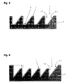
- Fig. 3 shows an embossing plate 4 according to the invention, in the opposite of the stamping plate Fig. 2 in each case between the first flank of a depression and the second flank of this depression a second planar region 6 or a further plateau 6 is arranged, which is aligned substantially parallel to the surface of the embossing plate.
- Fig. 4 shows an embossing plate 4 according to the invention, in the opposite of the stamping plate Fig. 2 the areas 3 are lowered relative to the surface of the embossing plate by the distance a.
- the distance a is preferably 5 ⁇ m to 100 ⁇ m, particularly preferably 10 ⁇ m to 50 ⁇ m and very particularly preferably 10 ⁇ m to 30 ⁇ m.
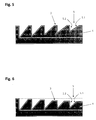
- Fig. 5 shows an embossing plate 4 according to the invention, in the opposite of the stamping plate Fig. 2 the depth of each recess 5 is different. In the illustrated embodiment, the depth of the recesses is smaller from left to right. The dashed line represents the depth t of the left depression.
- Fig. 6 shows an embossing plate 4 according to the invention, in the opposite of the stamping plate Fig. 5 in addition, the distance between the regions 3 is lowered relative to the surface of the stamping plate. In the illustrated embodiment, the distance of the areas 3 from left to right becomes larger.
- the dashed Lines represent the depth t of the left depression and the top of the die without depressions.
Landscapes
- Engineering & Computer Science (AREA)
- Manufacturing & Machinery (AREA)
- Credit Cards Or The Like (AREA)
- Shaping Of Tube Ends By Bending Or Straightening (AREA)
Applications Claiming Priority (1)
| Application Number | Priority Date | Filing Date | Title |
|---|---|---|---|
| DE102015009786.5A DE102015009786A1 (de) | 2015-07-27 | 2015-07-27 | Prägewerkzeug zur Herstellung eines Sicherheitselements mit einer optisch variablen Struktur |
Publications (2)
| Publication Number | Publication Date |
|---|---|
| EP3124285A1 true EP3124285A1 (fr) | 2017-02-01 |
| EP3124285B1 EP3124285B1 (fr) | 2020-06-17 |
Family
ID=56567335
Family Applications (1)
| Application Number | Title | Priority Date | Filing Date |
|---|---|---|---|
| EP16001620.0A Active EP3124285B1 (fr) | 2015-07-27 | 2016-07-25 | Outil d'estampage destine a fabriquer un element de securite ayant une structure optique variable |
Country Status (2)
| Country | Link |
|---|---|
| EP (1) | EP3124285B1 (fr) |
| DE (1) | DE102015009786A1 (fr) |
Cited By (3)
| Publication number | Priority date | Publication date | Assignee | Title |
|---|---|---|---|---|
| EP3511177A1 (fr) | 2018-01-12 | 2019-07-17 | Giesecke+Devrient Currency Technology GmbH | Élément de sécurité doté d'une structure estampée optiquement variable |
| CN110712443A (zh) * | 2019-10-12 | 2020-01-21 | 成都印钞有限公司 | 一种凹凸纹理模具及其制作方法、应用 |
| IT201800007607A1 (it) * | 2018-07-30 | 2020-01-30 | Focus Trade Srl | Piastre e metodo di goffratura |
Families Citing this family (2)
| Publication number | Priority date | Publication date | Assignee | Title |
|---|---|---|---|---|
| DE102017010913B3 (de) | 2017-11-25 | 2019-01-24 | Sack & Kiesselbach Maschinenfabrik Gmbh | Verfahren zum Betreiben einer Prägevorrichtung und Prägevorrichtung |
| DE102019124004A1 (de) * | 2019-09-06 | 2021-03-11 | Hueck Rheinische Gmbh | Presswerkzeug, Werkstück, Verfahren zum Herstellen eines Presswerkzeugs und Verfahren zum Herstellen eines Werkstücks |
Citations (8)
| Publication number | Priority date | Publication date | Assignee | Title |
|---|---|---|---|---|
| EP0429782A1 (fr) * | 1989-12-01 | 1991-06-05 | Landis & Gyr Technology Innovation AG | Dispositif pour modifier la protection contre la falsification d'un document de valeur |
| US5538753A (en) * | 1991-10-14 | 1996-07-23 | Landis & Gyr Betriebs Ag | Security element |
| WO2000020217A1 (fr) | 1998-10-02 | 2000-04-13 | Giesecke & Devrient Gmbh | Procede d'heliogravure destine a l'impression complete de grandes surfaces |
| DE10243653A9 (de) | 2002-09-19 | 2006-11-23 | Giesecke & Devrient Gmbh | Sicherheitspapier |
| EP1878584A2 (fr) * | 2006-07-13 | 2008-01-16 | OVD Kinegram AG | Corps multicouche à micro-optique |
| DE202012007473U1 (de) * | 2011-08-05 | 2012-08-29 | ALLTEC Angewandte Laserlicht Technologie Gesellschaft mit beschränkter Haftung | Reliefstruktur |
| WO2013045055A1 (fr) | 2011-09-30 | 2013-04-04 | Giesecke & Devrient Gmbh | Élément de sécurité présentant plusieurs structures optiquement variables |
| EP2886356A2 (fr) * | 2013-11-21 | 2015-06-24 | Giesecke & Devrient GmbH | Procédé de fabrication d'un document de valeur et d'un élément de sécurité, document de valeur et élément de sécurité ainsi obtenus et dispositif d'exécution du procédé |
Family Cites Families (11)
| Publication number | Priority date | Publication date | Assignee | Title |
|---|---|---|---|---|
| JP5600382B2 (ja) | 2007-05-07 | 2014-10-01 | ジェイディーエス ユニフェイズ コーポレーション | 回転により色を呈する構造化表面 |
| FR2942811B1 (fr) | 2009-03-04 | 2011-05-06 | Oberthur Technologies | Element de securite pour document-valeur. |
| US8741400B2 (en) | 2009-07-31 | 2014-06-03 | National Printing Bureau, Incorporated Administrative Agency | Latent image pattern formed body |
| DE102010047250A1 (de) | 2009-12-04 | 2011-06-09 | Giesecke & Devrient Gmbh | Sicherheitselement, Wertdokument mit einem solchen Sicherheitselement sowie Herstellungsverfahren eines Sicherheitselementes |
| DE102010019766A1 (de) | 2010-05-07 | 2011-11-10 | Giesecke & Devrient Gmbh | Verfahren zur Erzeugung einer Mikrostruktur auf einem Träger |
| DE102010048262A1 (de) | 2010-10-12 | 2012-04-12 | Giesecke & Devrient Gmbh | Darstellungselement |
| DE102010049617A1 (de) | 2010-10-26 | 2012-04-26 | Giesecke & Devrient Gmbh | Sicherheitselement mit optisch variablem Flächenmuster |
| FR2973398B1 (fr) | 2011-03-30 | 2013-04-12 | Oberthur Technologies | Element de securite pour un document-valeur, un procede de fabrication, et document correspondant |
| DE102011114645A1 (de) | 2011-09-30 | 2013-04-04 | Giesecke & Devrient Gmbh | Sicherheitselement mit einer optisch variablen Struktur aus Mikrospiegeln |
| WO2014124374A1 (fr) | 2013-02-08 | 2014-08-14 | Graphic Security Systems Corporation | Images latentes à ombre multiple |
| RU2516474C1 (ru) | 2013-04-09 | 2014-05-20 | Федеральное Государственное Унитарное Предприятие "Гознак" (Фгуп "Гознак") | Слоистое изделие на бумажной или полимерной основе (варианты) и способ его изготовления |
-
2015
- 2015-07-27 DE DE102015009786.5A patent/DE102015009786A1/de not_active Withdrawn
-
2016
- 2016-07-25 EP EP16001620.0A patent/EP3124285B1/fr active Active
Patent Citations (8)
| Publication number | Priority date | Publication date | Assignee | Title |
|---|---|---|---|---|
| EP0429782A1 (fr) * | 1989-12-01 | 1991-06-05 | Landis & Gyr Technology Innovation AG | Dispositif pour modifier la protection contre la falsification d'un document de valeur |
| US5538753A (en) * | 1991-10-14 | 1996-07-23 | Landis & Gyr Betriebs Ag | Security element |
| WO2000020217A1 (fr) | 1998-10-02 | 2000-04-13 | Giesecke & Devrient Gmbh | Procede d'heliogravure destine a l'impression complete de grandes surfaces |
| DE10243653A9 (de) | 2002-09-19 | 2006-11-23 | Giesecke & Devrient Gmbh | Sicherheitspapier |
| EP1878584A2 (fr) * | 2006-07-13 | 2008-01-16 | OVD Kinegram AG | Corps multicouche à micro-optique |
| DE202012007473U1 (de) * | 2011-08-05 | 2012-08-29 | ALLTEC Angewandte Laserlicht Technologie Gesellschaft mit beschränkter Haftung | Reliefstruktur |
| WO2013045055A1 (fr) | 2011-09-30 | 2013-04-04 | Giesecke & Devrient Gmbh | Élément de sécurité présentant plusieurs structures optiquement variables |
| EP2886356A2 (fr) * | 2013-11-21 | 2015-06-24 | Giesecke & Devrient GmbH | Procédé de fabrication d'un document de valeur et d'un élément de sécurité, document de valeur et élément de sécurité ainsi obtenus et dispositif d'exécution du procédé |
Cited By (6)
| Publication number | Priority date | Publication date | Assignee | Title |
|---|---|---|---|---|
| EP3511177A1 (fr) | 2018-01-12 | 2019-07-17 | Giesecke+Devrient Currency Technology GmbH | Élément de sécurité doté d'une structure estampée optiquement variable |
| DE102018000193A1 (de) | 2018-01-12 | 2019-07-18 | Giesecke+Devrient Currency Technology Gmbh | Sicherheitselement mit einer optisch variablen Prägestruktur |
| IT201800007607A1 (it) * | 2018-07-30 | 2020-01-30 | Focus Trade Srl | Piastre e metodo di goffratura |
| WO2020026109A1 (fr) * | 2018-07-30 | 2020-02-06 | Focus Trade S.R.L. | Plaques de gaufrage à contre-dépouille et procédé de gaufrage |
| CN110712443A (zh) * | 2019-10-12 | 2020-01-21 | 成都印钞有限公司 | 一种凹凸纹理模具及其制作方法、应用 |
| CN110712443B (zh) * | 2019-10-12 | 2021-12-14 | 成都印钞有限公司 | 一种凹凸纹理模具及其制作方法、应用 |
Also Published As
| Publication number | Publication date |
|---|---|
| DE102015009786A1 (de) | 2017-02-02 |
| EP3124285B1 (fr) | 2020-06-17 |
Similar Documents
| Publication | Publication Date | Title |
|---|---|---|
| EP1317351B1 (fr) | Support de donnees dote d'un element optiquement variable | |
| EP1119457B2 (fr) | Plaque et procede d'heliogravure destines a l'impression complete de grandes surfaces | |
| EP2173567B1 (fr) | Élément de sécurité présentant plusieurs structures optiquement variables | |
| EP1117543B1 (fr) | Support de donnees | |
| EP3074237B1 (fr) | Procédé de fabrication d'un élément de sécurité doté de pigments magnétiques orientables | |
| EP3124285B1 (fr) | Outil d'estampage destine a fabriquer un element de securite ayant une structure optique variable | |
| DE102011114647A1 (de) | Sicherheitselement mit mehreren optisch variablen Strukturen | |
| EP2007586A2 (fr) | Élément de sécurité comprenant des caractéristiques d'authenticité qui peut être identifié de manière visuelle ou tactile | |
| EP3418066B1 (fr) | Procédé de fabrication d'un outil d'estampage pour structures détectables de manière tactile | |
| EP3124284B1 (fr) | Structures tactiles sur des objets de valeur | |
| EP3498488B1 (fr) | Procede de fabrication d'un élément de sécurité doté d'une structure optique variable | |
| EP3511177B1 (fr) | Element de securite avec structure imprimee optiquement variable | |
| WO2018219498A1 (fr) | Élément de sécurité comprenant deux structures en relief | |
| EP3511175B1 (fr) | Élément de sécurité doté d'une structure optique variable d'éléments estampés agencés de manière statistique | |
| EP3877194A1 (fr) | Élément de sécurité doté d'éléments de structure associés spatialement les uns aux autres en couches différentes | |
| EP3511176B1 (fr) | Élément de sécurité doté d'une structure optique variable dans une cavité | |
| DE212019000397U1 (de) | Ein Sicherheitsdokument | |
| DE102021000689A1 (de) | Siebgewebe für Siebdruckverfahren und damit bedruckter Gegenstand | |
| EP3650242A1 (fr) | Outil d'estampage pour structures détectables tactilement | |
| DE202011104449U1 (de) | Sicherheitsdokument | |
| DE10208393A1 (de) | Sicherheitsdokument und Sicherheitselement für ein Sicherheitsdokument | |
| DE102018000686A1 (de) | Prägeplatte zur Erzeugung von geprägten Strukturen in einem Wertgegenstand und Verfahren zur Erzeugung einer Prägeplatte |
Legal Events
| Date | Code | Title | Description |
|---|---|---|---|
| PUAI | Public reference made under article 153(3) epc to a published international application that has entered the european phase |
Free format text: ORIGINAL CODE: 0009012 |
|
| STAA | Information on the status of an ep patent application or granted ep patent |
Free format text: STATUS: THE APPLICATION HAS BEEN PUBLISHED |
|
| AK | Designated contracting states |
Kind code of ref document: A1 Designated state(s): AL AT BE BG CH CY CZ DE DK EE ES FI FR GB GR HR HU IE IS IT LI LT LU LV MC MK MT NL NO PL PT RO RS SE SI SK SM TR |
|
| AX | Request for extension of the european patent |
Extension state: BA ME |
|
| STAA | Information on the status of an ep patent application or granted ep patent |
Free format text: STATUS: REQUEST FOR EXAMINATION WAS MADE |
|
| RAP1 | Party data changed (applicant data changed or rights of an application transferred) |
Owner name: GIESECKE+DEVRIENT CURRENCY TECHNOLOGY GMBH |
|
| 17P | Request for examination filed |
Effective date: 20170801 |
|
| RBV | Designated contracting states (corrected) |
Designated state(s): AL AT BE BG CH CY CZ DE DK EE ES FI FR GB GR HR HU IE IS IT LI LT LU LV MC MK MT NL NO PL PT RO RS SE SI SK SM TR |
|
| GRAP | Despatch of communication of intention to grant a patent |
Free format text: ORIGINAL CODE: EPIDOSNIGR1 |
|
| STAA | Information on the status of an ep patent application or granted ep patent |
Free format text: STATUS: GRANT OF PATENT IS INTENDED |
|
| RIC1 | Information provided on ipc code assigned before grant |
Ipc: B42D 25/425 20140101AFI20200121BHEP Ipc: B41M 3/14 20060101ALI20200121BHEP Ipc: B44B 5/02 20060101ALI20200121BHEP |
|
| INTG | Intention to grant announced |
Effective date: 20200205 |
|
| GRAS | Grant fee paid |
Free format text: ORIGINAL CODE: EPIDOSNIGR3 |
|
| GRAA | (expected) grant |
Free format text: ORIGINAL CODE: 0009210 |
|
| STAA | Information on the status of an ep patent application or granted ep patent |
Free format text: STATUS: THE PATENT HAS BEEN GRANTED |
|
| AK | Designated contracting states |
Kind code of ref document: B1 Designated state(s): AL AT BE BG CH CY CZ DE DK EE ES FI FR GB GR HR HU IE IS IT LI LT LU LV MC MK MT NL NO PL PT RO RS SE SI SK SM TR |
|
| REG | Reference to a national code |
Ref country code: GB Ref legal event code: FG4D Free format text: NOT ENGLISH |
|
| REG | Reference to a national code |
Ref country code: CH Ref legal event code: EP |
|
| REG | Reference to a national code |
Ref country code: IE Ref legal event code: FG4D Free format text: LANGUAGE OF EP DOCUMENT: GERMAN |
|
| REG | Reference to a national code |
Ref country code: DE Ref legal event code: R096 Ref document number: 502016010219 Country of ref document: DE |
|
| REG | Reference to a national code |
Ref country code: AT Ref legal event code: REF Ref document number: 1280859 Country of ref document: AT Kind code of ref document: T Effective date: 20200715 |
|
| PG25 | Lapsed in a contracting state [announced via postgrant information from national office to epo] |
Ref country code: LT Free format text: LAPSE BECAUSE OF FAILURE TO SUBMIT A TRANSLATION OF THE DESCRIPTION OR TO PAY THE FEE WITHIN THE PRESCRIBED TIME-LIMIT Effective date: 20200617 Ref country code: GR Free format text: LAPSE BECAUSE OF FAILURE TO SUBMIT A TRANSLATION OF THE DESCRIPTION OR TO PAY THE FEE WITHIN THE PRESCRIBED TIME-LIMIT Effective date: 20200918 Ref country code: SE Free format text: LAPSE BECAUSE OF FAILURE TO SUBMIT A TRANSLATION OF THE DESCRIPTION OR TO PAY THE FEE WITHIN THE PRESCRIBED TIME-LIMIT Effective date: 20200617 Ref country code: NO Free format text: LAPSE BECAUSE OF FAILURE TO SUBMIT A TRANSLATION OF THE DESCRIPTION OR TO PAY THE FEE WITHIN THE PRESCRIBED TIME-LIMIT Effective date: 20200917 Ref country code: FI Free format text: LAPSE BECAUSE OF FAILURE TO SUBMIT A TRANSLATION OF THE DESCRIPTION OR TO PAY THE FEE WITHIN THE PRESCRIBED TIME-LIMIT Effective date: 20200617 |
|
| REG | Reference to a national code |
Ref country code: LT Ref legal event code: MG4D |
|
| REG | Reference to a national code |
Ref country code: NL Ref legal event code: MP Effective date: 20200617 |
|
| PG25 | Lapsed in a contracting state [announced via postgrant information from national office to epo] |
Ref country code: HR Free format text: LAPSE BECAUSE OF FAILURE TO SUBMIT A TRANSLATION OF THE DESCRIPTION OR TO PAY THE FEE WITHIN THE PRESCRIBED TIME-LIMIT Effective date: 20200617 Ref country code: RS Free format text: LAPSE BECAUSE OF FAILURE TO SUBMIT A TRANSLATION OF THE DESCRIPTION OR TO PAY THE FEE WITHIN THE PRESCRIBED TIME-LIMIT Effective date: 20200617 Ref country code: LV Free format text: LAPSE BECAUSE OF FAILURE TO SUBMIT A TRANSLATION OF THE DESCRIPTION OR TO PAY THE FEE WITHIN THE PRESCRIBED TIME-LIMIT Effective date: 20200617 |
|
| PG25 | Lapsed in a contracting state [announced via postgrant information from national office to epo] |
Ref country code: AL Free format text: LAPSE BECAUSE OF FAILURE TO SUBMIT A TRANSLATION OF THE DESCRIPTION OR TO PAY THE FEE WITHIN THE PRESCRIBED TIME-LIMIT Effective date: 20200617 Ref country code: NL Free format text: LAPSE BECAUSE OF FAILURE TO SUBMIT A TRANSLATION OF THE DESCRIPTION OR TO PAY THE FEE WITHIN THE PRESCRIBED TIME-LIMIT Effective date: 20200617 |
|
| PG25 | Lapsed in a contracting state [announced via postgrant information from national office to epo] |
Ref country code: PT Free format text: LAPSE BECAUSE OF FAILURE TO SUBMIT A TRANSLATION OF THE DESCRIPTION OR TO PAY THE FEE WITHIN THE PRESCRIBED TIME-LIMIT Effective date: 20201019 Ref country code: RO Free format text: LAPSE BECAUSE OF FAILURE TO SUBMIT A TRANSLATION OF THE DESCRIPTION OR TO PAY THE FEE WITHIN THE PRESCRIBED TIME-LIMIT Effective date: 20200617 Ref country code: ES Free format text: LAPSE BECAUSE OF FAILURE TO SUBMIT A TRANSLATION OF THE DESCRIPTION OR TO PAY THE FEE WITHIN THE PRESCRIBED TIME-LIMIT Effective date: 20200617 Ref country code: CZ Free format text: LAPSE BECAUSE OF FAILURE TO SUBMIT A TRANSLATION OF THE DESCRIPTION OR TO PAY THE FEE WITHIN THE PRESCRIBED TIME-LIMIT Effective date: 20200617 Ref country code: EE Free format text: LAPSE BECAUSE OF FAILURE TO SUBMIT A TRANSLATION OF THE DESCRIPTION OR TO PAY THE FEE WITHIN THE PRESCRIBED TIME-LIMIT Effective date: 20200617 Ref country code: SM Free format text: LAPSE BECAUSE OF FAILURE TO SUBMIT A TRANSLATION OF THE DESCRIPTION OR TO PAY THE FEE WITHIN THE PRESCRIBED TIME-LIMIT Effective date: 20200617 Ref country code: IT Free format text: LAPSE BECAUSE OF FAILURE TO SUBMIT A TRANSLATION OF THE DESCRIPTION OR TO PAY THE FEE WITHIN THE PRESCRIBED TIME-LIMIT Effective date: 20200617 |
|
| PG25 | Lapsed in a contracting state [announced via postgrant information from national office to epo] |
Ref country code: SK Free format text: LAPSE BECAUSE OF FAILURE TO SUBMIT A TRANSLATION OF THE DESCRIPTION OR TO PAY THE FEE WITHIN THE PRESCRIBED TIME-LIMIT Effective date: 20200617 Ref country code: PL Free format text: LAPSE BECAUSE OF FAILURE TO SUBMIT A TRANSLATION OF THE DESCRIPTION OR TO PAY THE FEE WITHIN THE PRESCRIBED TIME-LIMIT Effective date: 20200617 Ref country code: IS Free format text: LAPSE BECAUSE OF FAILURE TO SUBMIT A TRANSLATION OF THE DESCRIPTION OR TO PAY THE FEE WITHIN THE PRESCRIBED TIME-LIMIT Effective date: 20201017 |
|
| REG | Reference to a national code |
Ref country code: CH Ref legal event code: PL |
|
| REG | Reference to a national code |
Ref country code: DE Ref legal event code: R026 Ref document number: 502016010219 Country of ref document: DE |
|
| PLBI | Opposition filed |
Free format text: ORIGINAL CODE: 0009260 |
|
| PLAX | Notice of opposition and request to file observation + time limit sent |
Free format text: ORIGINAL CODE: EPIDOSNOBS2 |
|
| PG25 | Lapsed in a contracting state [announced via postgrant information from national office to epo] |
Ref country code: MC Free format text: LAPSE BECAUSE OF FAILURE TO SUBMIT A TRANSLATION OF THE DESCRIPTION OR TO PAY THE FEE WITHIN THE PRESCRIBED TIME-LIMIT Effective date: 20200617 |
|
| 26 | Opposition filed |
Opponent name: OBERTHUR FIDUCIAIRE SAS / VHP SECURITY PAPER B.V. Effective date: 20210317 |
|
| REG | Reference to a national code |
Ref country code: BE Ref legal event code: MM Effective date: 20200731 |
|
| PG25 | Lapsed in a contracting state [announced via postgrant information from national office to epo] |
Ref country code: CH Free format text: LAPSE BECAUSE OF NON-PAYMENT OF DUE FEES Effective date: 20200731 Ref country code: DK Free format text: LAPSE BECAUSE OF FAILURE TO SUBMIT A TRANSLATION OF THE DESCRIPTION OR TO PAY THE FEE WITHIN THE PRESCRIBED TIME-LIMIT Effective date: 20200617 Ref country code: LU Free format text: LAPSE BECAUSE OF NON-PAYMENT OF DUE FEES Effective date: 20200725 Ref country code: LI Free format text: LAPSE BECAUSE OF NON-PAYMENT OF DUE FEES Effective date: 20200731 |
|
| PG25 | Lapsed in a contracting state [announced via postgrant information from national office to epo] |
Ref country code: BE Free format text: LAPSE BECAUSE OF NON-PAYMENT OF DUE FEES Effective date: 20200731 Ref country code: SI Free format text: LAPSE BECAUSE OF FAILURE TO SUBMIT A TRANSLATION OF THE DESCRIPTION OR TO PAY THE FEE WITHIN THE PRESCRIBED TIME-LIMIT Effective date: 20200617 |
|
| PLBB | Reply of patent proprietor to notice(s) of opposition received |
Free format text: ORIGINAL CODE: EPIDOSNOBS3 |
|
| PG25 | Lapsed in a contracting state [announced via postgrant information from national office to epo] |
Ref country code: IE Free format text: LAPSE BECAUSE OF NON-PAYMENT OF DUE FEES Effective date: 20200725 |
|
| PG25 | Lapsed in a contracting state [announced via postgrant information from national office to epo] |
Ref country code: TR Free format text: LAPSE BECAUSE OF FAILURE TO SUBMIT A TRANSLATION OF THE DESCRIPTION OR TO PAY THE FEE WITHIN THE PRESCRIBED TIME-LIMIT Effective date: 20200617 Ref country code: CY Free format text: LAPSE BECAUSE OF FAILURE TO SUBMIT A TRANSLATION OF THE DESCRIPTION OR TO PAY THE FEE WITHIN THE PRESCRIBED TIME-LIMIT Effective date: 20200617 |
|
| PG25 | Lapsed in a contracting state [announced via postgrant information from national office to epo] |
Ref country code: MK Free format text: LAPSE BECAUSE OF FAILURE TO SUBMIT A TRANSLATION OF THE DESCRIPTION OR TO PAY THE FEE WITHIN THE PRESCRIBED TIME-LIMIT Effective date: 20200617 |
|
| REG | Reference to a national code |
Ref country code: FR Ref legal event code: PLFP Year of fee payment: 7 |
|
| PLCK | Communication despatched that opposition was rejected |
Free format text: ORIGINAL CODE: EPIDOSNREJ1 |
|
| APBM | Appeal reference recorded |
Free format text: ORIGINAL CODE: EPIDOSNREFNO |
|
| APBP | Date of receipt of notice of appeal recorded |
Free format text: ORIGINAL CODE: EPIDOSNNOA2O |
|
| APAH | Appeal reference modified |
Free format text: ORIGINAL CODE: EPIDOSCREFNO |
|
| RAP4 | Party data changed (patent owner data changed or rights of a patent transferred) |
Owner name: GIESECKE+DEVRIENT CURRENCY TECHNOLOGY GMBH |
|
| REG | Reference to a national code |
Ref country code: DE Ref legal event code: R100 Ref document number: 502016010219 Country of ref document: DE |
|
| APBU | Appeal procedure closed |
Free format text: ORIGINAL CODE: EPIDOSNNOA9O |
|
| PLBN | Opposition rejected |
Free format text: ORIGINAL CODE: 0009273 |
|
| STAA | Information on the status of an ep patent application or granted ep patent |
Free format text: STATUS: OPPOSITION REJECTED |
|
| 27O | Opposition rejected |
Effective date: 20230320 |
|
| P01 | Opt-out of the competence of the unified patent court (upc) registered |
Effective date: 20230520 |
|
| PGFP | Annual fee paid to national office [announced via postgrant information from national office to epo] |
Ref country code: DE Payment date: 20250722 Year of fee payment: 10 |
|
| PGFP | Annual fee paid to national office [announced via postgrant information from national office to epo] |
Ref country code: BG Payment date: 20250718 Year of fee payment: 10 Ref country code: GB Payment date: 20250717 Year of fee payment: 10 |
|
| PGFP | Annual fee paid to national office [announced via postgrant information from national office to epo] |
Ref country code: FR Payment date: 20250723 Year of fee payment: 10 Ref country code: AT Payment date: 20250721 Year of fee payment: 10 |
|
| PGFP | Annual fee paid to national office [announced via postgrant information from national office to epo] |
Ref country code: MT Payment date: 20250724 Year of fee payment: 10 |