EP3124779B1 - Bypasskanalverkleidung für turbofan-triebwerk mit niedrigem nebenstromverhältnis und turbofan-triebwerk damit - Google Patents
Bypasskanalverkleidung für turbofan-triebwerk mit niedrigem nebenstromverhältnis und turbofan-triebwerk damit Download PDFInfo
- Publication number
- EP3124779B1 EP3124779B1 EP15840659.5A EP15840659A EP3124779B1 EP 3124779 B1 EP3124779 B1 EP 3124779B1 EP 15840659 A EP15840659 A EP 15840659A EP 3124779 B1 EP3124779 B1 EP 3124779B1
- Authority
- EP
- European Patent Office
- Prior art keywords
- bypass duct
- fairing
- bypass
- turbofan engine
- aft
- Prior art date
- Legal status (The legal status is an assumption and is not a legal conclusion. Google has not performed a legal analysis and makes no representation as to the accuracy of the status listed.)
- Active
Links
Images

Classifications
-
- F—MECHANICAL ENGINEERING; LIGHTING; HEATING; WEAPONS; BLASTING
- F04—POSITIVE - DISPLACEMENT MACHINES FOR LIQUIDS; PUMPS FOR LIQUIDS OR ELASTIC FLUIDS
- F04D—NON-POSITIVE-DISPLACEMENT PUMPS
- F04D27/00—Control, e.g. regulation, of pumps, pumping installations or pumping systems specially adapted for elastic fluids
- F04D27/009—Control, e.g. regulation, of pumps, pumping installations or pumping systems specially adapted for elastic fluids by bleeding, by passing or recycling fluid
-
- F—MECHANICAL ENGINEERING; LIGHTING; HEATING; WEAPONS; BLASTING
- F01—MACHINES OR ENGINES IN GENERAL; ENGINE PLANTS IN GENERAL; STEAM ENGINES
- F01D—NON-POSITIVE DISPLACEMENT MACHINES OR ENGINES, e.g. STEAM TURBINES
- F01D25/00—Component parts, details, or accessories, not provided for in, or of interest apart from, other groups
- F01D25/24—Casings; Casing parts, e.g. diaphragms, casing fastenings
-
- F—MECHANICAL ENGINEERING; LIGHTING; HEATING; WEAPONS; BLASTING
- F02—COMBUSTION ENGINES; HOT-GAS OR COMBUSTION-PRODUCT ENGINE PLANTS
- F02K—JET-PROPULSION PLANTS
- F02K3/00—Plants including a gas turbine driving a compressor or a ducted fan
- F02K3/02—Plants including a gas turbine driving a compressor or a ducted fan in which part of the working fluid by-passes the turbine and combustion chamber
- F02K3/04—Plants including a gas turbine driving a compressor or a ducted fan in which part of the working fluid by-passes the turbine and combustion chamber the plant including ducted fans, i.e. fans with high volume, low pressure outputs, for augmenting the jet thrust, e.g. of double-flow type
- F02K3/06—Plants including a gas turbine driving a compressor or a ducted fan in which part of the working fluid by-passes the turbine and combustion chamber the plant including ducted fans, i.e. fans with high volume, low pressure outputs, for augmenting the jet thrust, e.g. of double-flow type with front fan
-
- F—MECHANICAL ENGINEERING; LIGHTING; HEATING; WEAPONS; BLASTING
- F05—INDEXING SCHEMES RELATING TO ENGINES OR PUMPS IN VARIOUS SUBCLASSES OF CLASSES F01-F04
- F05D—INDEXING SCHEME FOR ASPECTS RELATING TO NON-POSITIVE-DISPLACEMENT MACHINES OR ENGINES, GAS-TURBINES OR JET-PROPULSION PLANTS
- F05D2250/00—Geometry
- F05D2250/70—Shape
- F05D2250/72—Shape symmetric
Definitions
- the disclosure herein relates to a fairing installed in a bypass duct and particularly to a fairing installed in a bypass duct for rectifying a bypass flow in a low bypass ratio turbofan engine and a turbofan engine therewith.
- turbojet engine In a turbojet engine, hot gas flow generated by a combustor, if ejected aftward with no change, has excessive velocity relative to the flight speed, and therefore generates great resistance to the ambient air. This leads to little expectation of high thrust efficiency particularly in low flight speeds.
- This problem may be solved by conducting part of air flow generated by a fan or a compressor thereof to bypass a core engine into a bypass duct and then ejecting it aftward.
- An engine of this type is referred to as a turbofan engine, which is well known because the bypass flow having proper velocity relative to the ambient air prominently improves thrust efficiency.
- bypass ratio The ratio of the amount of air flowing into the bypass duct to the amount of air flowing into the core engine is referred to as a bypass ratio.
- bypass ratios In engines used for aviation up to subsonic speeds, bypass ratios of four or more, namely high bypass ratios, are selected. Because it is expected to improve fuel efficiency as the bypass ratio is increased, engines with bypass ratios that exceeds eight are recently in practical use.
- a bypass duct In order to minimize energy loss, in a normally selected structure, a bypass duct is shortened to eject the bypass flow directly into the ambient air.
- low bypass ratio turbofan engines with bypass ratios of two or less are used.
- bypass flow is conducted through a relatively long bypass duct to a part just behind a turbine and is mixed there and ejected through a nozzle.
- low bypass ratio turbofan engines have inherent structural difference as compared with those with high bypass ratios apart from a difference in the bypass ratios.
- Patent Literatures 1 and 2 disclose arts related to low bypass ratio turbofan engines.
- Patent Literature 3 discloses a gas turbine engine provided with a foreign matter removal passage, wherein the intake passage includes an inlet portion, a curved portion and a reduced diameter portion.
- the bypass duct is curved away from the central axial line in a region corresponding to the curved portion and reduced diameter portion of the intake passage. Between the intake passage and bypass duct is defined an annular space.
- Patent Literature 4 discloses a fan assembly of a multistage tip fan, wherein the fan assembly comprises an outer fan first stage and an outer fan second stage both extending radially outward from an arcuate platform.
- a fairing with a bypass duct for diverting compressed air in part from a high pressure compressor and a combustor toward a turbine outlet of a turbofan engine having an axis is comprised of an outer casing and an inner casing defining the bypass duct around the high pressure compressor and the combustor, when installed, the bypass duct having an inlet just behind a low pressure compressor of the turbofan engine and an outlet opened at the turbine outlet, when installed; a fore section elongated aftward from the inner casing at the inlet of the bypass duct and running along an internal periphery of the outer casing; and an aft section elongated aftward in succession to the fore section and curved in a direction getting away from the internal periphery so as to increase an area of a flow path toward the rear, the whole of the aft section being curved, wherein the aft section terminates at an aft end being
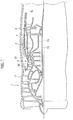
- a low bypass ratio turbofan engine is comprised of a low pressure compressor 1, a high pressure compressor 3, a combustor 5, a high pressure turbine 7, and a low pressure turbine 9, which are arranged in this order from its nose to the tail.
- the whole thereof is housed in an outer casing 17, and is, aside from the low pressure compressor 1, further housed in an inner casing 19.
- the outer casing 17 and the inner casing 19 define a bypass duct 21 therebetween, and its inlet I is opened just behind the low pressure compressor 1 and its outlet O is opened at a turbine outlet 11.
- Rotor blades of the low pressure turbine 9 and rotor blades of the low pressure compressor 1 are mutually connected via an inner drive shaft 13, which is rotatably supported by the outer casing 17 or the inner casing 19 with having bearings interposed therebetween.
- Rotor blades of the high pressure turbine 7 and rotor blades of the high pressure compressor 3 are mutually connected via an outer drive shaft 15, which is rotatably supported by the inner drive shaft 13 with having bearings interposed therebetween. They may alternately be supported by the outer casing 17 or the inner casing 19.
- the inner drive shaft 13 and the outer drive shaft 15 are coaxial and respectively rotatable about the axis of the engine.
- the high pressure turbine 7 extracts part of energy thereof to drive the high pressure compressor 3, and the low pressure turbine 9 extracts the rest of the energy to drive the low pressure compressor 1.
- the low pressure compressor 1 uses this driving force to compress and eject air aftward.
- the compressed air diverges at the inlet I of the bypass duct 21 into a main flow M and a bypass flow B1.
- the main flow M flows into the high pressure compressor 3 and the high pressure compressor 3 further compresses and supplies it to the combustor 5.
- the bypass flow B1 makes a detour around the combustor 5 to flow into the bypass duct 21.
- the bypass duct 21 is adjacent to the high pressure compressor 3 and the combustor 5 across the inner casing 19.
- structures for operation thereof such as a variable device 31 for driving vanes 23, 25, nozzles 33 for supplying the fuel into the combustor 5, igniters 35, and extractor tubes 37 for extracting part of the compressed air for example, are exposed on the outer face of the inner casing 19 toward the bypass duct 21.
- a fairing 41 is provided at the inlet I of the bypass duct 21. While each drawing only shows a section of the fairing 41 in a plane through the axis of the engine, the fairing 41 is a body of revolution about the axis. It may be a revolutionary body continuous about the axis but may have some partial cutouts or any structures added thereon.
- the fairing 41 extends aftward from the inner casing 19 and runs along an internal periphery of the outer casing 17.
- the bypass flow B1 is thereby rectified to flow along the internal periphery of the outer casing 17 (bypass flow B2). This prevents fast bypass flow from directly impinging on the aforementioned structures 31, 33, 35 and 37, thereby being helpful in reducing pressure loss.
- the fairing 41 at least a fore section 41f of thereof, may be formed in parallel with the internal periphery of the outer casing 17.
- Parallelism here is not necessarily strict but they may form an angle of about a few degrees.
- Either the whole or any part of the fore section 41f may be parallel with the internal periphery.
- the part in parallel forms a constant sectional area A1 and therefore this is not intended to cause reduction in speed and pressure of the bypass flow B1.
- the faring 41 gradually increases the area of the flow path toward the rear, thereby having a structure that decelerates the bypass flow B1.
- An aft section 41a elongated aftward in succession to the fore section 41f curves in a direction getting away from the internal periphery of the outer casing 17.
- This curve is preferably rendered smooth in view of prevention of creation of air resistance, and may be formed in a shape along an arc. In the case where it's along an arc, this curved section may run along an annular face described by rotating an arc about the axis of the engine. In view of reducing air resistance, it is more advantageous as a radius of curvature R of the curved section comes greater, and thus the radius may be about 1m for example.
- the aft section 41a may be totally formed as the curved section but the curved section may be limited to a part thereof. Further, the fore section 41f may be also curved and its radius of curvature may be identical to or different from that of the aft section 41a.
- An aft end of the aft section 41a may be terminated midway in the bypass duct 21.
- the aft section 41a at this aft end may be parallel with the axis of the engine.
- An area A2 of the flow path, at this aft end, is greater than the area A1 at the inlet, thereby decelerating the bypass flow B1.
- a slow air flow S in the bypass duct 21 when mixing with the fast bypass flow, creates resistance and therefore may be a major source for pressure loss.
- the resistance is reduced, thereby decreasing the pressure loss.
- the area ratio A2/A1 is from 1.5 to 2.0.
- the length of the fairing 41 from its fore end to the aft end, an overly short length of course causes reduction of the effects but an overly long length leads to saturation of another effect in view of the action of rectifying the flow.
- the length from the fore end to the aft end may be in the range of from 0.25L to 0.5 L, where the total length of the bypass duct 21 (from the inlet I to the outlet O) is L.
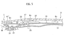
- the aft section 41a may not terminate midway but may be connected to the inner casing 19 as shown in FIG. 5 so that the fairing 41' covers the structures such as the variable device 31.
- FIG. 5 illustrates as if the structures 33, 35 and 37 are exposed to the bypass duct 21, the fairing 41' may be elongated to the outlet of the bypass duct 21 so as to cover these structures. As long as the structures on the outer periphery of the inner casing 19, such as the structures 31, 33, 35 and 37, are covered, they are prevented from causing pressure loss.
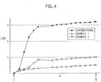
- FIG. 4 is an example of CFD analysis results given on a premise in which dimensions and flow rates are those in an actual airplane, where the abscissa axis means an axial distance D based on the inlet I and the ordinate axis means a pressure loss L expressed in percentage.
- a straight rectifier plate without any curved section is applied instead of the fairing in the present embodiment.
- the fairing has a curved rear section in which a radius of curvature is 1m and its length is 0.25L in accordance with the present embodiment.
- the fairing is elongated to cover the structures on the outer periphery of the inner casing.
- a pressure loss close to 3% occurs in the range of 0.3L from the inlet of the bypass duct. This is mainly caused by that fast bypass flow mixes with slow air flow in the bypass duct. The pressure loss grows greater at the rear thereof and exceeds 3% at the outlet of the bypass duct.
- the pressure loss is suppressed below 1% in the range of 0.3L from the inlet of the bypass duct and is about 1% even at the outlet of the bypass duct. More specifically, the pressure loss is reduced down to 1/3 or less as compared with the conventional example. Further the pressure loss is about 0.5% in the example 2 where the fairing is elongated. The pressure loss is further suppressed.
- the effect of suppressing the pressure loss created by the present embodiment is apparent.
- a rectifier should be directed to the internal periphery of the outer casing.
- the present embodiment applies a fairing curved in a direction getting away from the internal periphery of the outer casing and then succeeds in reducing the pressure loss.
- the main part of the pressure loss comes from mixing with the slow air flow around the inlet of the bypass duct.
- the present embodiment has been reached on the basis of the finding of this fact and by employing a structure that slightly decelerates the bypass flow in order to reduce the pressure loss by the mixture.
- the length of the fairing in the present embodiment is in the range of 0.25-0.5L. It is further apparent that the pressure loss would be suppressed if the fairing was elongated up to the total length of the bypass duct.
- the bypass duct can be narrowed. This enables further reduction of the bypass flow rate and therefore leads to improvement in a high-speed aviation ability.
- a fairing contributes to reduction in pressure loss in a bypass duct is provided.
Landscapes
- Engineering & Computer Science (AREA)
- Mechanical Engineering (AREA)
- General Engineering & Computer Science (AREA)
- Chemical & Material Sciences (AREA)
- Combustion & Propulsion (AREA)
- Life Sciences & Earth Sciences (AREA)
- Sustainable Development (AREA)
- Structures Of Non-Positive Displacement Pumps (AREA)
Claims (6)
- Verkleidung (41) mit einem Mantelstromkanal (21) zum Umleiten von Druckluft teilweise von einem Hochdruckverdichter (3) und einer Brennkammer (5) in Richtung auf einen Turbinenauslass (11) eines Turbofan-Triebwerks, das eine Achse aufweist, wobei die Verkleidung (41) mit dem Mantelstromkanal (21) Folgendes umfasst:ein äußeres Gehäuse (17) und ein inneres Gehäuse (19), die den Mantelstromkanal (21) um den Hochdruckverdichter (3) und die Brennkammer (5) herum im Einbauzustand definieren, wobei der Mantelstromkanal (21) einen Einlass (I) aufweist direkt hinter einem Niederdruckverdichter (1) des Turbofan-Triebwerks und einen Auslass (0), der an dem Turbinenauslass (11) geöffnet ist, im Einbauzustand aufweist;einen vorderen Abschnitt (41f), der von dem inneren Gehäuse (19) aus an dem Einlass (I) des Mantelstromkanals (21) nach hinten länglich ist und entlang einer internen Peripherie des äußeren Gehäuses (17) verläuft; undeinen hinteren Abschnitt (41a), der im Anschluss an den vorderen Abschnitt (41f) nach hinten länglich ist und in einer Richtung gekrümmt ist, die sich von der internen Peripherie entfernt, um eine Fläche (A1, A2) eines Strömungswegs nach hinten zu vergrößern, wobei der gesamte hintere Abschnitt (41a) gekrümmt ist,wobei der hintere Abschnitt (41a) an einem hinteren Ende endet, das zu der Achse parallel ist, und
wobei ein Verhältnis der Fläche (A2) des Strömungswegs an dem hinteren Ende zu der Fläche (A1) des Strömungswegs an dem Einlass (I) zwischen 1,5 und 2,0 liegt. - Verkleidung (41) mit dem Mantelstromkanal (21) nach Anspruch 1, wobei der hintere Abschnitt (41a) an einem Bogen entlang gekrümmt ist.
- Verkleidung (41) mit dem Mantelstromkanal (21) nach Anspruch 2, wobei der hintere Abschnitt (41a) an einer ringförmigen Seite entlang verläuft, die durch Drehen eines Bogens um die Achse herum beschrieben wird.
- Verkleidung (41) mit dem Mantelstromkanal (21) nach Anspruch 1 oder 2, wobei der hintere Abschnitt (41a) länglich ist, um mit dem inneren Gehäuse (19) verbunden zu sein, wodurch der hintere Abschnitt (41a) Strukturen (33, 35, 37) auf einer äußeren Peripherie des inneren Gehäuses (19) abdeckt.
- Verkleidung (41) mit dem Mantelstromkanal (21) nach Anspruch 1 oder 2, wobei eine Gesamtlänge von dem vorderen Ende zu dem hinteren Ende 0,25 bis 0,5mal die Gesamtlänge des Mantelstromkanals (21) ist.
- Turbofan-Triebwerk, umfassend die Verkleidung (41) mit dem Mantelstromkanal (21) nach Anspruch 1 oder 2.
Applications Claiming Priority (2)
| Application Number | Priority Date | Filing Date | Title |
|---|---|---|---|
| JP2014184253A JP6507535B2 (ja) | 2014-09-10 | 2014-09-10 | 低バイパス比ターボファンエンジンのためのバイパスダクトフェアリングおよびそれを備えたターボファンエンジン |
| PCT/JP2015/072899 WO2016039068A1 (ja) | 2014-09-10 | 2015-08-13 | 低バイパス比ターボファンエンジンのためのバイパスダクトフェアリングおよびそれを備えたターボファンエンジン |
Publications (3)
| Publication Number | Publication Date |
|---|---|
| EP3124779A1 EP3124779A1 (de) | 2017-02-01 |
| EP3124779A4 EP3124779A4 (de) | 2017-11-22 |
| EP3124779B1 true EP3124779B1 (de) | 2019-03-06 |
Family
ID=55458826
Family Applications (1)
| Application Number | Title | Priority Date | Filing Date |
|---|---|---|---|
| EP15840659.5A Active EP3124779B1 (de) | 2014-09-10 | 2015-08-13 | Bypasskanalverkleidung für turbofan-triebwerk mit niedrigem nebenstromverhältnis und turbofan-triebwerk damit |
Country Status (4)
| Country | Link |
|---|---|
| US (1) | US10655630B2 (de) |
| EP (1) | EP3124779B1 (de) |
| JP (1) | JP6507535B2 (de) |
| WO (1) | WO2016039068A1 (de) |
Family Cites Families (25)
| Publication number | Priority date | Publication date | Assignee | Title |
|---|---|---|---|---|
| GB1313841A (en) * | 1967-01-18 | 1973-04-18 | Secr Defence | Gas turbine jet propulsion engine |
| US4175384A (en) | 1977-08-02 | 1979-11-27 | General Electric Company | Individual bypass injector valves for a double bypass variable cycle turbofan engine |
| JPS58107842A (ja) | 1981-12-22 | 1983-06-27 | Tech Res & Dev Inst Of Japan Def Agency | タ−ボフアンエンジンにおける可変スプリツタ装置 |
| JPS6119820A (ja) | 1984-07-09 | 1986-01-28 | Oji Paper Co Ltd | 多孔質炭素板の製造方法 |
| US5680754A (en) * | 1990-02-12 | 1997-10-28 | General Electric Company | Compressor splitter for use with a forward variable area bypass injector |
| US5048286A (en) | 1990-06-29 | 1991-09-17 | General Electric Company | Bypass valve door |
| JPH06102991A (ja) | 1992-09-21 | 1994-04-15 | Ricoh Co Ltd | ペン型入力装置 |
| JP2000320306A (ja) * | 1999-05-13 | 2000-11-21 | Ishikawajima Harima Heavy Ind Co Ltd | 薄肉構造物の防振熱応力低減取付構造 |
| JP2001050110A (ja) | 1999-08-09 | 2001-02-23 | Ishikawajima Harima Heavy Ind Co Ltd | ターボファンエンジンの可変バイパスノズル装置 |
| US6217277B1 (en) | 1999-10-05 | 2001-04-17 | Pratt & Whitney Canada Corp. | Turbofan engine including improved fan blade lining |
| US6901739B2 (en) | 2003-10-07 | 2005-06-07 | General Electric Company | Gas turbine engine with variable pressure ratio fan system |
| JP4279245B2 (ja) * | 2004-12-06 | 2009-06-17 | 本田技研工業株式会社 | ガスタービンエンジン |
| FR2891313A1 (fr) | 2005-09-26 | 2007-03-30 | Airbus France Sas | Turbomoteur a double flux pourvu d'un prerefroidisseur |
| US8387362B2 (en) | 2006-10-19 | 2013-03-05 | Michael Ralph Storage | Method and apparatus for operating gas turbine engine heat exchangers |
| US7765789B2 (en) * | 2006-12-15 | 2010-08-03 | General Electric Company | Apparatus and method for assembling gas turbine engines |
| DE102009033755A1 (de) * | 2009-07-17 | 2011-01-20 | Rolls-Royce Deutschland Ltd & Co Kg | Turbofantriebwerk |
| US8695324B2 (en) * | 2009-11-20 | 2014-04-15 | General Electric Co. | Multistage tip fan |
| US20120034064A1 (en) | 2010-08-06 | 2012-02-09 | General Electric Company | Contoured axial-radial exhaust diffuser |
| US20130104522A1 (en) * | 2011-11-01 | 2013-05-02 | Daniel B. Kupratis | Gas turbine engine with variable pitch first stage fan section |
| GB201121889D0 (en) * | 2011-12-20 | 2012-02-01 | Rolls Royce Plc | Active flow control intake for a gas turbine engine |
| JP5982837B2 (ja) | 2012-01-30 | 2016-08-31 | 株式会社Ihi | 航空機用ジェットエンジンのファン動翼 |
| US9200531B2 (en) * | 2012-01-31 | 2015-12-01 | United Technologies Corporation | Fan case rub system, components, and their manufacture |
| JP6035946B2 (ja) | 2012-07-26 | 2016-11-30 | 株式会社Ihi | エンジンダクト及び航空機エンジン |
| JP3196426U (ja) | 2014-10-14 | 2015-03-12 | 株式会社ナカネ | 箱入り表示ベスト |
| US9915149B2 (en) * | 2015-08-27 | 2018-03-13 | Rolls-Royce North American Technologies Inc. | System and method for a fluidic barrier on the low pressure side of a fan blade |
-
2014
- 2014-09-10 JP JP2014184253A patent/JP6507535B2/ja active Active
-
2015
- 2015-08-13 WO PCT/JP2015/072899 patent/WO2016039068A1/ja not_active Ceased
- 2015-08-13 EP EP15840659.5A patent/EP3124779B1/de active Active
-
2016
- 2016-10-03 US US15/284,119 patent/US10655630B2/en active Active
Non-Patent Citations (1)
| Title |
|---|
| None * |
Also Published As
| Publication number | Publication date |
|---|---|
| EP3124779A4 (de) | 2017-11-22 |
| JP2016056747A (ja) | 2016-04-21 |
| JP6507535B2 (ja) | 2019-05-08 |
| US10655630B2 (en) | 2020-05-19 |
| EP3124779A1 (de) | 2017-02-01 |
| WO2016039068A1 (ja) | 2016-03-17 |
| US20170022996A1 (en) | 2017-01-26 |
Similar Documents
| Publication | Publication Date | Title |
|---|---|---|
| US8967967B2 (en) | Propfan engine | |
| US7921637B2 (en) | High bypass-ratio turbofan jet engine | |
| US9033668B2 (en) | Impeller | |
| CN104520542B (zh) | 包括多个被安装在风扇上游的固定径向叶片的涡轮机组 | |
| CN108930557B (zh) | 用于压缩机导叶前缘辅助导叶的方法及系统 | |
| US11441438B2 (en) | Bleed air extraction device for a gas turbine engine | |
| US9534497B2 (en) | Inter-turbine ducts with variable area ratios | |
| US9644537B2 (en) | Free stream intake with particle separator for reverse core engine | |
| US8845286B2 (en) | Inter-turbine ducts with guide vanes | |
| US11002141B2 (en) | Method and system for leading edge auxiliary turbine vanes | |
| EP3597895A1 (de) | Mantelstromtriebwerk eines überschallflugzeugs | |
| US11131205B2 (en) | Inter-turbine ducts with flow control mechanisms | |
| EP2971550B1 (de) | Schaufellüfterummantelung mit bereichsregelung | |
| US20180216576A1 (en) | Supersonic turbofan engine | |
| US10519976B2 (en) | Fluid diodes with ridges to control boundary layer in axial compressor stator vane | |
| EP3354848B1 (de) | Zwischenturbinenkanäle mit mehreren zwischenschaufeln | |
| US6351940B1 (en) | Inverter ducting for dual fan concept | |
| EP3124779B1 (de) | Bypasskanalverkleidung für turbofan-triebwerk mit niedrigem nebenstromverhältnis und turbofan-triebwerk damit | |
| US20140260183A1 (en) | Variable cycle intake for reverse core engine | |
| CN116457560B (zh) | 具有改善的推进效率的航空推进系统 |
Legal Events
| Date | Code | Title | Description |
|---|---|---|---|
| STAA | Information on the status of an ep patent application or granted ep patent |
Free format text: STATUS: THE INTERNATIONAL PUBLICATION HAS BEEN MADE |
|
| PUAI | Public reference made under article 153(3) epc to a published international application that has entered the european phase |
Free format text: ORIGINAL CODE: 0009012 |
|
| STAA | Information on the status of an ep patent application or granted ep patent |
Free format text: STATUS: REQUEST FOR EXAMINATION WAS MADE |
|
| 17P | Request for examination filed |
Effective date: 20161027 |
|
| AK | Designated contracting states |
Kind code of ref document: A1 Designated state(s): AL AT BE BG CH CY CZ DE DK EE ES FI FR GB GR HR HU IE IS IT LI LT LU LV MC MK MT NL NO PL PT RO RS SE SI SK SM TR |
|
| AX | Request for extension of the european patent |
Extension state: BA ME |
|
| A4 | Supplementary search report drawn up and despatched |
Effective date: 20171025 |
|
| RIC1 | Information provided on ipc code assigned before grant |
Ipc: F02K 3/06 20060101AFI20171019BHEP Ipc: F01D 25/24 20060101ALI20171019BHEP |
|
| DAV | Request for validation of the european patent (deleted) | ||
| DAX | Request for extension of the european patent (deleted) | ||
| GRAP | Despatch of communication of intention to grant a patent |
Free format text: ORIGINAL CODE: EPIDOSNIGR1 |
|
| STAA | Information on the status of an ep patent application or granted ep patent |
Free format text: STATUS: GRANT OF PATENT IS INTENDED |
|
| RIC1 | Information provided on ipc code assigned before grant |
Ipc: F02K 3/06 20060101AFI20180828BHEP Ipc: F01D 25/24 20060101ALI20180828BHEP |
|
| INTG | Intention to grant announced |
Effective date: 20180926 |
|
| GRAS | Grant fee paid |
Free format text: ORIGINAL CODE: EPIDOSNIGR3 |
|
| GRAA | (expected) grant |
Free format text: ORIGINAL CODE: 0009210 |
|
| STAA | Information on the status of an ep patent application or granted ep patent |
Free format text: STATUS: THE PATENT HAS BEEN GRANTED |
|
| AK | Designated contracting states |
Kind code of ref document: B1 Designated state(s): AL AT BE BG CH CY CZ DE DK EE ES FI FR GB GR HR HU IE IS IT LI LT LU LV MC MK MT NL NO PL PT RO RS SE SI SK SM TR |
|
| REG | Reference to a national code |
Ref country code: GB Ref legal event code: FG4D |
|
| REG | Reference to a national code |
Ref country code: CH Ref legal event code: EP Ref country code: AT Ref legal event code: REF Ref document number: 1104872 Country of ref document: AT Kind code of ref document: T Effective date: 20190315 |
|
| REG | Reference to a national code |
Ref country code: DE Ref legal event code: R096 Ref document number: 602015026073 Country of ref document: DE |
|
| REG | Reference to a national code |
Ref country code: IE Ref legal event code: FG4D |
|
| REG | Reference to a national code |
Ref country code: NL Ref legal event code: MP Effective date: 20190306 |
|
| REG | Reference to a national code |
Ref country code: LT Ref legal event code: MG4D |
|
| PG25 | Lapsed in a contracting state [announced via postgrant information from national office to epo] |
Ref country code: NO Free format text: LAPSE BECAUSE OF FAILURE TO SUBMIT A TRANSLATION OF THE DESCRIPTION OR TO PAY THE FEE WITHIN THE PRESCRIBED TIME-LIMIT Effective date: 20190606 Ref country code: LT Free format text: LAPSE BECAUSE OF FAILURE TO SUBMIT A TRANSLATION OF THE DESCRIPTION OR TO PAY THE FEE WITHIN THE PRESCRIBED TIME-LIMIT Effective date: 20190306 Ref country code: FI Free format text: LAPSE BECAUSE OF FAILURE TO SUBMIT A TRANSLATION OF THE DESCRIPTION OR TO PAY THE FEE WITHIN THE PRESCRIBED TIME-LIMIT Effective date: 20190306 Ref country code: SE Free format text: LAPSE BECAUSE OF FAILURE TO SUBMIT A TRANSLATION OF THE DESCRIPTION OR TO PAY THE FEE WITHIN THE PRESCRIBED TIME-LIMIT Effective date: 20190306 |
|
| PG25 | Lapsed in a contracting state [announced via postgrant information from national office to epo] |
Ref country code: RS Free format text: LAPSE BECAUSE OF FAILURE TO SUBMIT A TRANSLATION OF THE DESCRIPTION OR TO PAY THE FEE WITHIN THE PRESCRIBED TIME-LIMIT Effective date: 20190306 Ref country code: NL Free format text: LAPSE BECAUSE OF FAILURE TO SUBMIT A TRANSLATION OF THE DESCRIPTION OR TO PAY THE FEE WITHIN THE PRESCRIBED TIME-LIMIT Effective date: 20190306 Ref country code: BG Free format text: LAPSE BECAUSE OF FAILURE TO SUBMIT A TRANSLATION OF THE DESCRIPTION OR TO PAY THE FEE WITHIN THE PRESCRIBED TIME-LIMIT Effective date: 20190606 Ref country code: HR Free format text: LAPSE BECAUSE OF FAILURE TO SUBMIT A TRANSLATION OF THE DESCRIPTION OR TO PAY THE FEE WITHIN THE PRESCRIBED TIME-LIMIT Effective date: 20190306 Ref country code: LV Free format text: LAPSE BECAUSE OF FAILURE TO SUBMIT A TRANSLATION OF THE DESCRIPTION OR TO PAY THE FEE WITHIN THE PRESCRIBED TIME-LIMIT Effective date: 20190306 Ref country code: GR Free format text: LAPSE BECAUSE OF FAILURE TO SUBMIT A TRANSLATION OF THE DESCRIPTION OR TO PAY THE FEE WITHIN THE PRESCRIBED TIME-LIMIT Effective date: 20190607 |
|
| REG | Reference to a national code |
Ref country code: AT Ref legal event code: MK05 Ref document number: 1104872 Country of ref document: AT Kind code of ref document: T Effective date: 20190306 |
|
| PG25 | Lapsed in a contracting state [announced via postgrant information from national office to epo] |
Ref country code: PT Free format text: LAPSE BECAUSE OF FAILURE TO SUBMIT A TRANSLATION OF THE DESCRIPTION OR TO PAY THE FEE WITHIN THE PRESCRIBED TIME-LIMIT Effective date: 20190706 Ref country code: EE Free format text: LAPSE BECAUSE OF FAILURE TO SUBMIT A TRANSLATION OF THE DESCRIPTION OR TO PAY THE FEE WITHIN THE PRESCRIBED TIME-LIMIT Effective date: 20190306 Ref country code: AL Free format text: LAPSE BECAUSE OF FAILURE TO SUBMIT A TRANSLATION OF THE DESCRIPTION OR TO PAY THE FEE WITHIN THE PRESCRIBED TIME-LIMIT Effective date: 20190306 Ref country code: RO Free format text: LAPSE BECAUSE OF FAILURE TO SUBMIT A TRANSLATION OF THE DESCRIPTION OR TO PAY THE FEE WITHIN THE PRESCRIBED TIME-LIMIT Effective date: 20190306 Ref country code: IT Free format text: LAPSE BECAUSE OF FAILURE TO SUBMIT A TRANSLATION OF THE DESCRIPTION OR TO PAY THE FEE WITHIN THE PRESCRIBED TIME-LIMIT Effective date: 20190306 Ref country code: SK Free format text: LAPSE BECAUSE OF FAILURE TO SUBMIT A TRANSLATION OF THE DESCRIPTION OR TO PAY THE FEE WITHIN THE PRESCRIBED TIME-LIMIT Effective date: 20190306 Ref country code: ES Free format text: LAPSE BECAUSE OF FAILURE TO SUBMIT A TRANSLATION OF THE DESCRIPTION OR TO PAY THE FEE WITHIN THE PRESCRIBED TIME-LIMIT Effective date: 20190306 Ref country code: CZ Free format text: LAPSE BECAUSE OF FAILURE TO SUBMIT A TRANSLATION OF THE DESCRIPTION OR TO PAY THE FEE WITHIN THE PRESCRIBED TIME-LIMIT Effective date: 20190306 |
|
| PG25 | Lapsed in a contracting state [announced via postgrant information from national office to epo] |
Ref country code: SM Free format text: LAPSE BECAUSE OF FAILURE TO SUBMIT A TRANSLATION OF THE DESCRIPTION OR TO PAY THE FEE WITHIN THE PRESCRIBED TIME-LIMIT Effective date: 20190306 Ref country code: PL Free format text: LAPSE BECAUSE OF FAILURE TO SUBMIT A TRANSLATION OF THE DESCRIPTION OR TO PAY THE FEE WITHIN THE PRESCRIBED TIME-LIMIT Effective date: 20190306 |
|
| REG | Reference to a national code |
Ref country code: DE Ref legal event code: R097 Ref document number: 602015026073 Country of ref document: DE |
|
| PG25 | Lapsed in a contracting state [announced via postgrant information from national office to epo] |
Ref country code: IS Free format text: LAPSE BECAUSE OF FAILURE TO SUBMIT A TRANSLATION OF THE DESCRIPTION OR TO PAY THE FEE WITHIN THE PRESCRIBED TIME-LIMIT Effective date: 20190706 Ref country code: AT Free format text: LAPSE BECAUSE OF FAILURE TO SUBMIT A TRANSLATION OF THE DESCRIPTION OR TO PAY THE FEE WITHIN THE PRESCRIBED TIME-LIMIT Effective date: 20190306 |
|
| PLBE | No opposition filed within time limit |
Free format text: ORIGINAL CODE: 0009261 |
|
| STAA | Information on the status of an ep patent application or granted ep patent |
Free format text: STATUS: NO OPPOSITION FILED WITHIN TIME LIMIT |
|
| PG25 | Lapsed in a contracting state [announced via postgrant information from national office to epo] |
Ref country code: DK Free format text: LAPSE BECAUSE OF FAILURE TO SUBMIT A TRANSLATION OF THE DESCRIPTION OR TO PAY THE FEE WITHIN THE PRESCRIBED TIME-LIMIT Effective date: 20190306 |
|
| 26N | No opposition filed |
Effective date: 20191209 |
|
| PG25 | Lapsed in a contracting state [announced via postgrant information from national office to epo] |
Ref country code: SI Free format text: LAPSE BECAUSE OF FAILURE TO SUBMIT A TRANSLATION OF THE DESCRIPTION OR TO PAY THE FEE WITHIN THE PRESCRIBED TIME-LIMIT Effective date: 20190306 |
|
| PG25 | Lapsed in a contracting state [announced via postgrant information from national office to epo] |
Ref country code: TR Free format text: LAPSE BECAUSE OF FAILURE TO SUBMIT A TRANSLATION OF THE DESCRIPTION OR TO PAY THE FEE WITHIN THE PRESCRIBED TIME-LIMIT Effective date: 20190306 |
|
| PG25 | Lapsed in a contracting state [announced via postgrant information from national office to epo] |
Ref country code: CH Free format text: LAPSE BECAUSE OF NON-PAYMENT OF DUE FEES Effective date: 20190831 Ref country code: LI Free format text: LAPSE BECAUSE OF NON-PAYMENT OF DUE FEES Effective date: 20190831 Ref country code: MC Free format text: LAPSE BECAUSE OF FAILURE TO SUBMIT A TRANSLATION OF THE DESCRIPTION OR TO PAY THE FEE WITHIN THE PRESCRIBED TIME-LIMIT Effective date: 20190306 Ref country code: LU Free format text: LAPSE BECAUSE OF NON-PAYMENT OF DUE FEES Effective date: 20190813 |
|
| REG | Reference to a national code |
Ref country code: BE Ref legal event code: MM Effective date: 20190831 |
|
| PG25 | Lapsed in a contracting state [announced via postgrant information from national office to epo] |
Ref country code: IE Free format text: LAPSE BECAUSE OF NON-PAYMENT OF DUE FEES Effective date: 20190813 |
|
| PG25 | Lapsed in a contracting state [announced via postgrant information from national office to epo] |
Ref country code: BE Free format text: LAPSE BECAUSE OF NON-PAYMENT OF DUE FEES Effective date: 20190831 |
|
| PG25 | Lapsed in a contracting state [announced via postgrant information from national office to epo] |
Ref country code: CY Free format text: LAPSE BECAUSE OF FAILURE TO SUBMIT A TRANSLATION OF THE DESCRIPTION OR TO PAY THE FEE WITHIN THE PRESCRIBED TIME-LIMIT Effective date: 20190306 |
|
| PG25 | Lapsed in a contracting state [announced via postgrant information from national office to epo] |
Ref country code: MT Free format text: LAPSE BECAUSE OF FAILURE TO SUBMIT A TRANSLATION OF THE DESCRIPTION OR TO PAY THE FEE WITHIN THE PRESCRIBED TIME-LIMIT Effective date: 20190306 Ref country code: HU Free format text: LAPSE BECAUSE OF FAILURE TO SUBMIT A TRANSLATION OF THE DESCRIPTION OR TO PAY THE FEE WITHIN THE PRESCRIBED TIME-LIMIT; INVALID AB INITIO Effective date: 20150813 |
|
| PG25 | Lapsed in a contracting state [announced via postgrant information from national office to epo] |
Ref country code: MK Free format text: LAPSE BECAUSE OF FAILURE TO SUBMIT A TRANSLATION OF THE DESCRIPTION OR TO PAY THE FEE WITHIN THE PRESCRIBED TIME-LIMIT Effective date: 20190306 |
|
| PGFP | Annual fee paid to national office [announced via postgrant information from national office to epo] |
Ref country code: DE Payment date: 20250724 Year of fee payment: 11 |
|
| PGFP | Annual fee paid to national office [announced via postgrant information from national office to epo] |
Ref country code: GB Payment date: 20250724 Year of fee payment: 11 |
|
| PGFP | Annual fee paid to national office [announced via postgrant information from national office to epo] |
Ref country code: FR Payment date: 20250725 Year of fee payment: 11 |