EP3125017A1 - Appareil d'affichage d'images - Google Patents
Appareil d'affichage d'images Download PDFInfo
- Publication number
- EP3125017A1 EP3125017A1 EP15768794.8A EP15768794A EP3125017A1 EP 3125017 A1 EP3125017 A1 EP 3125017A1 EP 15768794 A EP15768794 A EP 15768794A EP 3125017 A1 EP3125017 A1 EP 3125017A1
- Authority
- EP
- European Patent Office
- Prior art keywords
- mode
- eye
- image
- luminance
- viewer
- Prior art date
- Legal status (The legal status is an assumption and is not a legal conclusion. Google has not performed a legal analysis and makes no representation as to the accuracy of the status listed.)
- Withdrawn
Links
Images



Classifications
-
- H—ELECTRICITY
- H04—ELECTRIC COMMUNICATION TECHNIQUE
- H04N—PICTORIAL COMMUNICATION, e.g. TELEVISION
- H04N13/00—Stereoscopic video systems; Multi-view video systems; Details thereof
- H04N13/30—Image reproducers
- H04N13/398—Synchronisation thereof; Control thereof
-
- B—PERFORMING OPERATIONS; TRANSPORTING
- B60—VEHICLES IN GENERAL
- B60K—ARRANGEMENT OR MOUNTING OF PROPULSION UNITS OR OF TRANSMISSIONS IN VEHICLES; ARRANGEMENT OR MOUNTING OF PLURAL DIVERSE PRIME-MOVERS IN VEHICLES; AUXILIARY DRIVES FOR VEHICLES; INSTRUMENTATION OR DASHBOARDS FOR VEHICLES; ARRANGEMENTS IN CONNECTION WITH COOLING, AIR INTAKE, GAS EXHAUST OR FUEL SUPPLY OF PROPULSION UNITS IN VEHICLES
- B60K35/00—Instruments specially adapted for vehicles; Arrangement of instruments in or on vehicles
- B60K35/20—Output arrangements, i.e. from vehicle to user, associated with vehicle functions or specially adapted therefor
- B60K35/21—Output arrangements, i.e. from vehicle to user, associated with vehicle functions or specially adapted therefor using visual output, e.g. blinking lights or matrix displays
- B60K35/211—Output arrangements, i.e. from vehicle to user, associated with vehicle functions or specially adapted therefor using visual output, e.g. blinking lights or matrix displays producing three-dimensional [3D] effects, e.g. stereoscopic images
-
- B—PERFORMING OPERATIONS; TRANSPORTING
- B60—VEHICLES IN GENERAL
- B60K—ARRANGEMENT OR MOUNTING OF PROPULSION UNITS OR OF TRANSMISSIONS IN VEHICLES; ARRANGEMENT OR MOUNTING OF PLURAL DIVERSE PRIME-MOVERS IN VEHICLES; AUXILIARY DRIVES FOR VEHICLES; INSTRUMENTATION OR DASHBOARDS FOR VEHICLES; ARRANGEMENTS IN CONNECTION WITH COOLING, AIR INTAKE, GAS EXHAUST OR FUEL SUPPLY OF PROPULSION UNITS IN VEHICLES
- B60K35/00—Instruments specially adapted for vehicles; Arrangement of instruments in or on vehicles
- B60K35/20—Output arrangements, i.e. from vehicle to user, associated with vehicle functions or specially adapted therefor
- B60K35/21—Output arrangements, i.e. from vehicle to user, associated with vehicle functions or specially adapted therefor using visual output, e.g. blinking lights or matrix displays
- B60K35/22—Display screens
-
- B—PERFORMING OPERATIONS; TRANSPORTING
- B60—VEHICLES IN GENERAL
- B60K—ARRANGEMENT OR MOUNTING OF PROPULSION UNITS OR OF TRANSMISSIONS IN VEHICLES; ARRANGEMENT OR MOUNTING OF PLURAL DIVERSE PRIME-MOVERS IN VEHICLES; AUXILIARY DRIVES FOR VEHICLES; INSTRUMENTATION OR DASHBOARDS FOR VEHICLES; ARRANGEMENTS IN CONNECTION WITH COOLING, AIR INTAKE, GAS EXHAUST OR FUEL SUPPLY OF PROPULSION UNITS IN VEHICLES
- B60K35/00—Instruments specially adapted for vehicles; Arrangement of instruments in or on vehicles
- B60K35/60—Instruments characterised by their location or relative disposition in or on vehicles
-
- B—PERFORMING OPERATIONS; TRANSPORTING
- B60—VEHICLES IN GENERAL
- B60K—ARRANGEMENT OR MOUNTING OF PROPULSION UNITS OR OF TRANSMISSIONS IN VEHICLES; ARRANGEMENT OR MOUNTING OF PLURAL DIVERSE PRIME-MOVERS IN VEHICLES; AUXILIARY DRIVES FOR VEHICLES; INSTRUMENTATION OR DASHBOARDS FOR VEHICLES; ARRANGEMENTS IN CONNECTION WITH COOLING, AIR INTAKE, GAS EXHAUST OR FUEL SUPPLY OF PROPULSION UNITS IN VEHICLES
- B60K35/00—Instruments specially adapted for vehicles; Arrangement of instruments in or on vehicles
- B60K35/80—Arrangements for controlling instruments
- B60K35/81—Arrangements for controlling instruments for controlling displays
-
- G—PHYSICS
- G02—OPTICS
- G02B—OPTICAL ELEMENTS, SYSTEMS OR APPARATUS
- G02B27/00—Optical systems or apparatus not provided for by any of the groups G02B1/00 - G02B26/00, G02B30/00
- G02B27/01—Head-up displays
- G02B27/0101—Head-up displays characterised by optical features
-
- G—PHYSICS
- G02—OPTICS
- G02B—OPTICAL ELEMENTS, SYSTEMS OR APPARATUS
- G02B30/00—Optical systems or apparatus for producing three-dimensional [3D] effects, e.g. stereoscopic images
- G02B30/20—Optical systems or apparatus for producing three-dimensional [3D] effects, e.g. stereoscopic images by providing first and second parallax images to an observer's left and right eyes
- G02B30/26—Optical systems or apparatus for producing three-dimensional [3D] effects, e.g. stereoscopic images by providing first and second parallax images to an observer's left and right eyes of the autostereoscopic type
- G02B30/27—Optical systems or apparatus for producing three-dimensional [3D] effects, e.g. stereoscopic images by providing first and second parallax images to an observer's left and right eyes of the autostereoscopic type involving lenticular arrays
-
- G—PHYSICS
- G02—OPTICS
- G02B—OPTICAL ELEMENTS, SYSTEMS OR APPARATUS
- G02B30/00—Optical systems or apparatus for producing three-dimensional [3D] effects, e.g. stereoscopic images
- G02B30/20—Optical systems or apparatus for producing three-dimensional [3D] effects, e.g. stereoscopic images by providing first and second parallax images to an observer's left and right eyes
- G02B30/26—Optical systems or apparatus for producing three-dimensional [3D] effects, e.g. stereoscopic images by providing first and second parallax images to an observer's left and right eyes of the autostereoscopic type
- G02B30/30—Optical systems or apparatus for producing three-dimensional [3D] effects, e.g. stereoscopic images by providing first and second parallax images to an observer's left and right eyes of the autostereoscopic type involving parallax barriers
-
- H—ELECTRICITY
- H04—ELECTRIC COMMUNICATION TECHNIQUE
- H04N—PICTORIAL COMMUNICATION, e.g. TELEVISION
- H04N13/00—Stereoscopic video systems; Multi-view video systems; Details thereof
- H04N13/10—Processing, recording or transmission of stereoscopic or multi-view image signals
- H04N13/106—Processing image signals
- H04N13/128—Adjusting depth or disparity
-
- H—ELECTRICITY
- H04—ELECTRIC COMMUNICATION TECHNIQUE
- H04N—PICTORIAL COMMUNICATION, e.g. TELEVISION
- H04N13/00—Stereoscopic video systems; Multi-view video systems; Details thereof
- H04N13/10—Processing, recording or transmission of stereoscopic or multi-view image signals
- H04N13/106—Processing image signals
- H04N13/144—Processing image signals for flicker reduction
-
- H—ELECTRICITY
- H04—ELECTRIC COMMUNICATION TECHNIQUE
- H04N—PICTORIAL COMMUNICATION, e.g. TELEVISION
- H04N13/00—Stereoscopic video systems; Multi-view video systems; Details thereof
- H04N13/30—Image reproducers
- H04N13/302—Image reproducers for viewing without the aid of special glasses, i.e. using autostereoscopic displays
- H04N13/31—Image reproducers for viewing without the aid of special glasses, i.e. using autostereoscopic displays using parallax barriers
-
- H—ELECTRICITY
- H04—ELECTRIC COMMUNICATION TECHNIQUE
- H04N—PICTORIAL COMMUNICATION, e.g. TELEVISION
- H04N13/00—Stereoscopic video systems; Multi-view video systems; Details thereof
- H04N13/30—Image reproducers
- H04N13/356—Image reproducers having separate monoscopic and stereoscopic modes
-
- H—ELECTRICITY
- H04—ELECTRIC COMMUNICATION TECHNIQUE
- H04N—PICTORIAL COMMUNICATION, e.g. TELEVISION
- H04N13/00—Stereoscopic video systems; Multi-view video systems; Details thereof
- H04N13/30—Image reproducers
- H04N13/356—Image reproducers having separate monoscopic and stereoscopic modes
- H04N13/359—Switching between monoscopic and stereoscopic modes
-
- B—PERFORMING OPERATIONS; TRANSPORTING
- B60—VEHICLES IN GENERAL
- B60K—ARRANGEMENT OR MOUNTING OF PROPULSION UNITS OR OF TRANSMISSIONS IN VEHICLES; ARRANGEMENT OR MOUNTING OF PLURAL DIVERSE PRIME-MOVERS IN VEHICLES; AUXILIARY DRIVES FOR VEHICLES; INSTRUMENTATION OR DASHBOARDS FOR VEHICLES; ARRANGEMENTS IN CONNECTION WITH COOLING, AIR INTAKE, GAS EXHAUST OR FUEL SUPPLY OF PROPULSION UNITS IN VEHICLES
- B60K2360/00—Indexing scheme associated with groups B60K35/00 or B60K37/00 relating to details of instruments or dashboards
- B60K2360/20—Optical features of instruments
- B60K2360/31—Virtual images
-
- B—PERFORMING OPERATIONS; TRANSPORTING
- B60—VEHICLES IN GENERAL
- B60K—ARRANGEMENT OR MOUNTING OF PROPULSION UNITS OR OF TRANSMISSIONS IN VEHICLES; ARRANGEMENT OR MOUNTING OF PLURAL DIVERSE PRIME-MOVERS IN VEHICLES; AUXILIARY DRIVES FOR VEHICLES; INSTRUMENTATION OR DASHBOARDS FOR VEHICLES; ARRANGEMENTS IN CONNECTION WITH COOLING, AIR INTAKE, GAS EXHAUST OR FUEL SUPPLY OF PROPULSION UNITS IN VEHICLES
- B60K35/00—Instruments specially adapted for vehicles; Arrangement of instruments in or on vehicles
- B60K35/50—Instruments characterised by their means of attachment to or integration in the vehicle
-
- G—PHYSICS
- G02—OPTICS
- G02B—OPTICAL ELEMENTS, SYSTEMS OR APPARATUS
- G02B27/00—Optical systems or apparatus not provided for by any of the groups G02B1/00 - G02B26/00, G02B30/00
- G02B27/01—Head-up displays
- G02B27/0101—Head-up displays characterised by optical features
- G02B2027/0129—Head-up displays characterised by optical features comprising devices for correcting parallax
-
- G—PHYSICS
- G02—OPTICS
- G02B—OPTICAL ELEMENTS, SYSTEMS OR APPARATUS
- G02B27/00—Optical systems or apparatus not provided for by any of the groups G02B1/00 - G02B26/00, G02B30/00
- G02B27/01—Head-up displays
- G02B27/0101—Head-up displays characterised by optical features
- G02B2027/0132—Head-up displays characterised by optical features comprising binocular systems
- G02B2027/0134—Head-up displays characterised by optical features comprising binocular systems of stereoscopic type
-
- H—ELECTRICITY
- H04—ELECTRIC COMMUNICATION TECHNIQUE
- H04N—PICTORIAL COMMUNICATION, e.g. TELEVISION
- H04N2213/00—Details of stereoscopic systems
- H04N2213/001—Constructional or mechanical details
Definitions
- the present disclosure relates to image display apparatuses which provide parallax images by using flat panel display devices.
- PTL 1 discloses a display apparatus mounted in a movable body, with the apparatus configuring a head-up display that utilizes a windshield of the body as a projection plate.
- the display apparatus includes a luminous flux generator, a reflector, a projection unit, and an orientation controller.
- the luminous flux generator generates luminous flux that contains image information.
- the reflector reflects the luminous flux generated by the luminous flux generator.
- the projection unit projects the luminous flux into either both left and right eyes or one of them.
- the orientation controller emits the luminous flux to a predetermined display region. This configuration allows switching between a both-eyes mode and a single-eye mode in the head-up display.
- An image display apparatus includes a display unit, an optical element, and a controller.
- the display unit outputs an image for right-eye and an image for left-eye, with the images having an amount of parallax between them.
- the optical element directs light, which has been output from the display unit, toward a right eye and a left eye of the viewer.
- the controller varies the parallax amount and the luminance of any one of the image for right-eye and the image for left-eye.
- the controller is capable of switching between a first mode of showing the images having the parallax amount therebetween to the viewer and a second mode of showing the corresponding image to any one of the eyes of the viewer. When switching from the first mode to the second mode, the controller gradually decreases the luminance of any one of the images for right-eye and for left-eye. When switching from the second mode to the first mode, the controller gradually increases the luminance that has been decreased.
- FIGS. 1 and 2 a first embodiment will be described with reference to FIGS. 1 and 2 .
- FIG. 1 shows a configuration of image display apparatus 10 according to the first embodiment.
- Image display apparatus 10 includes housing 100, display device 110, parallax barrier 103, optical system 120, and controller 104 such as a microcomputer.
- Display device 110, parallax barrier 103, optical system 120, and controller 104 are disposed inside housing 100.
- Image display apparatus 10 is disposed in the inside of the dashboard of a vehicle, for example.
- Display device 110 disposed inside housing 100 provides, via windshield 220, an image for viewer D present in the cabin of the vehicle, with the image being as virtual image I.
- Housing 100 includes opening 102 through which the image is projected. Opening 102 may be equipped with a transparent cover.
- Optical system 120 includes first mirror 121 and second mirror 122. Controller 104 controls both luminance of the image which is output from display device 110 and the amount of parallax between an image for left-eye and an image for right-eye.
- the image displayed by display device 110 is reflected by first mirror 121, second mirror 122, and windshield 220 in this order, and then travels along optical path X to viewing region 300 of viewer D. Viewer D visually recognizes the image, as virtual image I, which is displayed by display device 110.
- Display device 110 may employ a liquid crystal display device, an organic light emitting diode, a plasma display panel, or the like.
- first mirror 121 is disposed above display device 110 in the vertical direction.
- the reflection plane of first mirror 121 is arranged to face the second mirror.
- FIG. 2 is a view of the configuration including display device 110 and parallax barrier 103.
- Parallax barrier 103 is configured by depositing a light shielding material such as chromium, for example, onto a glass substrate (not shown).
- Parallax barrier 103 is formed in a one-dimensional striped pattern on the glass substrate.
- Apertures 151 are formed as portions on which the light shielding material has not been deposited.
- Display device 110 includes pixels each of which is configured with sub-pixels, i.e. a R(red), a G(green), and a B(blue) sub-pixel. In the first embodiment, these pixels are assigned to pixels 111 for left-eye and pixels 112 for right-eye, in an alternating manner.
- Parallax barrier 103 includes apertures 151. These apertures 151 control the orientation of light emitted from display device 110 such that the light emitted from the pixels 111 for left-eye reaches left eye 131 of the viewer while the light emitted from pixels 112 for right-eye reaches right eye 132 of the viewer. This configuration can provide an image having parallax for viewer D.
- FIG. 3 is a view illustrating a positional relation among the positions of the viewpoints (left eye 131 and right eye 132), virtual images I, and a stereoscopic vision image.
- parallax amount Q between the image for left-eye and the image for right-eye is varied to change convergence angle ⁇ in accordance with parallax amount Q, thereby changing stereoscopic visual range L of virtual images I that are shown to viewer D.
- image display apparatus 10 adopts display modes, i.e. a first mode (binocular vision mode) and a second mode (monocular vision mode).
- the first mode is one in which an image is displayed on both pixels 111 for left-eye and pixels 112 for right-eye.
- the second mode is one in which an image is displayed only on pixels 111 for left-eye, not on pixels 112 for right-eye, thereby showing the image only for the left eye of viewer D.
- the stereoscopic vision includes binocular stereoscopic vision and monocular stereoscopic vision.
- the binocular stereoscopic vision is the ability for the person to feel a stereognostic sense by means of the both eyes.
- the monocular stereoscopic vision is the ability for the person to feel the stereognostic sense by means of either the left or the right eye.
- factors of stereoscopic vision include convergence and parallax.
- factors of stereoscopic vision include: shielding, relative sizes, relative densities, heights in sight, motion parallax, aerial perspective, and focusing by a crystalline lens.
- the factors of binocular stereoscopic vision offer high contribution rates to the stereoscopic vision in a short visual range; however, their contribution rates decrease as the visual range becomes longer.
- shielding, relative sizes, and relative densities offer constant contribution rates independent of the visual range.
- the aerial perspective increases its contribution rate with increasing visual range.
- the first mode is adopted to change the stereoscopic visual range by means of both the factors of binocular stereoscopic vision and the factors of monocular stereoscopic vision.
- the second mode is adopted to change the stereoscopic visual range by means of only the factors of monocular stereoscopic vision.
- controller 104 controls the display device 110 such that a marker is displayed, in the first mode, at a position where stereoscopic visual range L is 3 meters, with the marker being displayed in so-called augmented reality (AR). If the forward-running vehicle being detected by the vehicle-mounted camera changes its speed so as to become more distant, e.g.
- AR augmented reality
- controller 104 changes the display mode for the marker by switching from the first mode to the second mode.
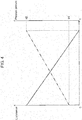
- controller 104 gradually decreases the luminance of pixels 112 for right-eye, as indicated by the solid line in FIG. 4 .
- the luminance of pixels 112 for right-eye finally reaches 0 (zero), which completes the switching over to the second mode.
- controller 104 changes the display mode for the marker by switching from the second mode to the first mode.
- controller 104 gradually increases the luminance of pixels 112 for right-eye.
- the display mode is completely switched to the first mode.
- the method for varying the luminance is not limited to one in which the luminance is varied continuously; the method may be one in which the luminance is varied in a step-by-step manner.
- the rate and the number of steps of varying the luminance are determined in accordance with factors including: the speed and acceleration of the vehicle concerned, the age of the viewer, the kind and position of the subject (e.g. a traffic sign, a forward vehicle, a passerby, etc.) indicated by the marker, and the degree of fatigue of the viewer due to hours of viewer's continuous driving. That is, when the vehicle concerned is running at a high speed, the rate of varying the luminance is made higher.
- the rate of varying the luminance is made lower.
- the rate of varying the luminance is made lower.
- the rate of varying the luminance is made higher.
- image display apparatus 10 adopts the first mode when the visual range of viewer D is not longer than 50 meters, and adopts the second mode when the visual range is longer than 50 meters. Then, when the mode is switched, the luminance of pixels 112 for right-eye is continuously gradually varied.
- image display apparatus 10 gradually switches between the first mode and the second mode, in accordance with the visual range of viewer D.
- This configuration allows the switching between the first mode (binocular vision mode) and the second mode (monocular vision mode), without causing viewer D to feel strains and something strange.
- image display apparatus 10 adopts the display modes, i.e. the first mode (binocular vision mode) and the second mode (monocular vision mode).
- the first mode is one in which an image is displayed on both pixels 111 for left-eye and pixels 112 for right-eye.
- the second mode is one in which an image is displayed only on pixels 111 for left-eye, not on pixels 112 for right-eye, thereby showing the image only to the left eye of viewer D.
- the first mode when the visual range of viewer D is not longer than 50 meters, the first mode is adopted to change stereoscopic visual range L by means of both the factors of binocular stereoscopic vision and the factors of monocular stereoscopic vision, as in the case of the first embodiment.
- the second mode is adopted to change the stereoscopic visual range by means of only the factors of monocular stereoscopic vision.
- controller 104 controls the display device 110 such that a marker is displayed, in the first mode, at a position where stereoscopic visual range L is 3 meters. If the forward-running vehicle being detected by the vehicle-mounted camera changes its speed so as to become more distant, e.g. not shorter than 50 meters away from the vehicle concerned, controller 104 changes the currently-adopted display mode of the marker by switching from the first mode to the second mode.
- the luminance of pixels 112 for right-eye is gradually decreased, as indicated by the solid line in FIG. 4 .
- the luminance of pixels 112 for right-eye becomes finally equal to 0 (zero), which completes the switching over to the second mode.
- the parallax amount as well is gradually varied simultaneously with the luminance being varied.
- ⁇ 1 be the parallax amount of image display apparatus 10 at stereoscopic visual range L of 3 meters.
- ⁇ 2 be the parallax amount in the case where a marker or the like is displayed, in the first mode, at a position with stereoscopic visual range L of 100 meters.
- the parallax amount is gradually increased from ⁇ 1 to ⁇ 2, in the same way for varying the luminance as that in the first embodiment.
- the relation between the luminance being varied and the parallax amount being varied is controlled such that the timing of decreasing the luminance down to 0 (zero) is coincide with the timing of increasing the parallax amount up to ⁇ 2.
- controller 104 gradually decreases the parallax amount from ⁇ 2 to ⁇ 1.
- the relation between the luminance being varied and the parallax amount being varied is controlled such that the timing at which the luminance of the image for right-eye becomes equal to that for left-eye is coincide with the timing at which the parallax amount decreases to ⁇ 1.
- the luminance and parallax amount may be varied continuously or, alternatively, in a step-by-step manner. Moreover, the rate and the number of the steps of varying the luminance and parallax amount are determined in accordance with factors including: the speed of the vehicle concerned, the age of the viewer, the kind and position of the subject (e.g. a traffic sign, a forward vehicle, a passerby, etc.) indicated by the marker, and the degree of fatigue of the viewer due to hours of viewer's continuous driving. Specifically, the luminance and parallax amount are varied at the same rates as those in the first embodiment.
- image display apparatus 10 adopts the first mode when the visual range of viewer D is not longer than 50 meters, and adopts the second mode when the visual range is longer than 50 meters.
- the mode is switched, both the luminance of pixels 112 for right-eye and the parallax amount Q are gradually varied.
- parallax amount Q as well as the luminance is varied when the mode is switched. This configuration allows the smoother switching of the mode without causing the viewer to feel strains and something strange, compared to the case where the luminance alone is varied.
- image display apparatus 10 gradually switches between the first mode and the second mode in accordance with stereoscopic visual range L of viewer D. This configuration allows the switching between the first mode (binocular vision mode) and the second mode
- the first and second embodiments have been described to exemplify the technology disclosed in the present application.
- the technology is not limited to these embodiments, and is also applicable to embodiments that are subjected, as appropriate, to various changes and modifications, replacements, additions, omissions, and the like.
- the technology disclosed herein also allows another embodiment which is configured by combining the appropriate constituent elements in the first and second embodiments described above.
- the descriptions have been made by using the case where the windshield is employed as a means for projecting images thereon.
- the means may be a combiner instead of the windshield, for example.
- the means for displaying stereoscopic images has been described by using the case where the space-sharing display device is used which employs the parallax barriers disposed therein.
- the means for displaying the stereoscopic image is not limited to this configuration and may also be implemented by using a time-sharing display device which displays the image alternately for the left and right eyes.
- the means for providing the left and right eyes with respective parallax images has been exemplified by the parallax barrier; however, such a means may also employ a lenticular lens or a liquid crystal lens, instead of the parallax barrier.
- the technology according to the present disclosure is applicable to stereoscopic image display apparatuses which are each mounted on movable bodies and capable of switching between monocular stereoscopic vision and binocular stereoscopic vision, in accordance with images to be displayed, situations of the surroundings of the movable bodies, and viewers of the images.
- the technology according to the disclosure is applicable to a head-up display and the like.
Landscapes
- Engineering & Computer Science (AREA)
- Multimedia (AREA)
- Signal Processing (AREA)
- Physics & Mathematics (AREA)
- Chemical & Material Sciences (AREA)
- Combustion & Propulsion (AREA)
- Transportation (AREA)
- Mechanical Engineering (AREA)
- Optics & Photonics (AREA)
- General Physics & Mathematics (AREA)
- Testing, Inspecting, Measuring Of Stereoscopic Televisions And Televisions (AREA)
- Instrument Panels (AREA)
- Transforming Electric Information Into Light Information (AREA)
- Controls And Circuits For Display Device (AREA)
Applications Claiming Priority (3)
| Application Number | Priority Date | Filing Date | Title |
|---|---|---|---|
| JP2014068186 | 2014-03-28 | ||
| JP2015005997A JP2015194709A (ja) | 2014-03-28 | 2015-01-15 | 画像表示装置 |
| PCT/JP2015/001379 WO2015146042A1 (fr) | 2014-03-28 | 2015-03-12 | Appareil d'affichage d'images |
Publications (2)
| Publication Number | Publication Date |
|---|---|
| EP3125017A1 true EP3125017A1 (fr) | 2017-02-01 |
| EP3125017A4 EP3125017A4 (fr) | 2017-03-01 |
Family
ID=54194596
Family Applications (1)
| Application Number | Title | Priority Date | Filing Date |
|---|---|---|---|
| EP15768794.8A Withdrawn EP3125017A4 (fr) | 2014-03-28 | 2015-03-12 | Appareil d'affichage d'images |
Country Status (4)
| Country | Link |
|---|---|
| US (1) | US20160173867A1 (fr) |
| EP (1) | EP3125017A4 (fr) |
| JP (1) | JP2015194709A (fr) |
| WO (1) | WO2015146042A1 (fr) |
Cited By (1)
| Publication number | Priority date | Publication date | Assignee | Title |
|---|---|---|---|---|
| EP3748417A4 (fr) * | 2018-02-01 | 2021-10-27 | Kyocera Corporation | Affichage tête haute, dispositif d'affichage pour affichage tête haute, et corps en mouvement |
Families Citing this family (20)
| Publication number | Priority date | Publication date | Assignee | Title |
|---|---|---|---|---|
| JP6535759B2 (ja) * | 2015-12-24 | 2019-06-26 | 京セラ株式会社 | 車両用ヘッドアップディスプレイシステム |
| JP6629889B2 (ja) * | 2016-02-05 | 2020-01-15 | マクセル株式会社 | ヘッドアップディスプレイ装置 |
| JP6784058B2 (ja) | 2016-05-23 | 2020-11-11 | 株式会社リコー | 情報表示装置 |
| CN106291956B (zh) * | 2016-08-26 | 2018-12-25 | 京东方科技集团股份有限公司 | 显示面板组件及其制备方法和显示装置 |
| US20190283607A1 (en) * | 2016-12-01 | 2019-09-19 | Sharp Kabushiki Kaisha | Display device and electronic mirror |
| JPWO2018110336A1 (ja) * | 2016-12-13 | 2019-10-24 | コニカミノルタ株式会社 | ヘッドアップディスプレイ装置 |
| US11215820B2 (en) | 2017-01-27 | 2022-01-04 | Osaka City University | Three-dimensional display apparatus, three-dimensional display system, head up display, head up display system, three-dimensional display apparatus design method, and mobile object |
| WO2018199185A1 (fr) * | 2017-04-26 | 2018-11-01 | 京セラ株式会社 | Dispositif d'affichage, système d'affichage et corps mobile |
| JP6873850B2 (ja) * | 2017-07-07 | 2021-05-19 | 京セラ株式会社 | 画像投影装置及び移動体 |
| US20190034743A1 (en) * | 2017-07-26 | 2019-01-31 | Benoit CHAUVEAU | Dashboard embedded driver monitoring system |
| KR102397089B1 (ko) * | 2017-07-28 | 2022-05-12 | 삼성전자주식회사 | 이미지 처리 방법 및 이미지 처리 장치 |
| JP7120537B2 (ja) * | 2017-10-31 | 2022-08-17 | 公立大学法人大阪 | 3次元表示装置、3次元表示システム、ヘッドアップディスプレイおよび3次元表示装置設計方法 |
| JP7129789B2 (ja) * | 2018-02-19 | 2022-09-02 | 京セラ株式会社 | ヘッドアップディスプレイ、ヘッドアップディスプレイシステム、および移動体 |
| JP6571819B2 (ja) * | 2018-02-20 | 2019-09-04 | 京セラ株式会社 | ヘッドアップディスプレイ及び移動体 |
| DE102018213820A1 (de) * | 2018-08-16 | 2020-02-20 | Bayerische Motoren Werke Aktiengesellschaft | Verfahren zum Betreiben einer Blickfeldanzeigevorrichtung für ein Kraftfahrzeug |
| JP2020067576A (ja) * | 2018-10-25 | 2020-04-30 | アイシン・エィ・ダブリュ株式会社 | 重畳画像表示装置及びコンピュータプログラム |
| JP7202191B2 (ja) * | 2019-01-17 | 2023-01-11 | マクセル株式会社 | 車両用情報表示システム |
| US20230001790A1 (en) * | 2019-11-05 | 2023-01-05 | Kyocera Corporation | Head-up display, head-up display system, and movable body |
| JP7332449B2 (ja) * | 2019-11-27 | 2023-08-23 | 京セラ株式会社 | ヘッドアップディスプレイモジュール、ヘッドアップディスプレイシステム及び移動体 |
| DE102019218627A1 (de) * | 2019-11-29 | 2021-06-02 | Volkswagen Aktiengesellschaft | Augmented-Reality-Head-up-Display |
Family Cites Families (27)
| Publication number | Priority date | Publication date | Assignee | Title |
|---|---|---|---|---|
| US3915548A (en) * | 1973-04-30 | 1975-10-28 | Hughes Aircraft Co | Holographic lens and liquid crystal image source for head-up display |
| JPS62186537U (fr) * | 1986-05-16 | 1987-11-27 | ||
| US5495576A (en) * | 1993-01-11 | 1996-02-27 | Ritchey; Kurtis J. | Panoramic image based virtual reality/telepresence audio-visual system and method |
| JPH0822091A (ja) * | 1994-07-05 | 1996-01-23 | Canon Inc | 立体画像記録方法および装置ならびに立体画像形成体 |
| JP3375944B2 (ja) * | 1998-03-27 | 2003-02-10 | 株式会社オプトウエア | 3次元画像表示装置 |
| JP3673217B2 (ja) * | 2001-12-20 | 2005-07-20 | オリンパス株式会社 | 映像表示装置 |
| KR101017231B1 (ko) * | 2002-10-30 | 2011-02-25 | 가부시키가이샤 한도오따이 에네루기 켄큐쇼 | 표시 장치 및 전자 기기 |
| EP1639394A2 (fr) * | 2003-06-10 | 2006-03-29 | Elop Electro-Optics Industries Ltd. | Procede et systeme servant a afficher une image informative sur une image d'arriere-plan |
| JP2005084569A (ja) * | 2003-09-11 | 2005-03-31 | Brother Ind Ltd | 画像表示装置 |
| ATE552478T1 (de) * | 2004-06-03 | 2012-04-15 | Making Virtual Solid L L C | Navigationsanzeigeverfahren und vorrichtung für unterwegs unter verwendung eines head-up-displays |
| EP1782228A1 (fr) * | 2004-08-03 | 2007-05-09 | Silverbrook Research Pty. Ltd | Impression en libre service |
| JP4501719B2 (ja) * | 2005-02-22 | 2010-07-14 | トヨタ自動車株式会社 | 車両遠隔操作装置 |
| US8434909B2 (en) * | 2007-10-09 | 2013-05-07 | Flex Lighting Ii, Llc | Light emitting display with light mixing within a film |
| JP2009128565A (ja) * | 2007-11-22 | 2009-06-11 | Toshiba Corp | 表示装置、表示方法及びヘッドアップディスプレイ |
| US20100149073A1 (en) * | 2008-11-02 | 2010-06-17 | David Chaum | Near to Eye Display System and Appliance |
| JP4686586B2 (ja) * | 2008-09-19 | 2011-05-25 | 株式会社東芝 | 車載用表示装置及び表示方法 |
| JP5075776B2 (ja) * | 2008-09-22 | 2012-11-21 | 株式会社東芝 | 表示装置及び移動体 |
| JP4886751B2 (ja) * | 2008-09-25 | 2012-02-29 | 株式会社東芝 | 車載用表示システム及び表示方法 |
| CN102124749B (zh) * | 2009-06-01 | 2013-05-29 | 松下电器产业株式会社 | 立体图像显示装置 |
| JP5425554B2 (ja) * | 2009-07-27 | 2014-02-26 | 富士フイルム株式会社 | 立体撮像装置及び立体撮像方法 |
| US8964298B2 (en) * | 2010-02-28 | 2015-02-24 | Microsoft Corporation | Video display modification based on sensor input for a see-through near-to-eye display |
| US20130278631A1 (en) * | 2010-02-28 | 2013-10-24 | Osterhout Group, Inc. | 3d positioning of augmented reality information |
| JP5235976B2 (ja) * | 2010-05-31 | 2013-07-10 | 株式会社ソニー・コンピュータエンタテインメント | 映像再生方法、および映像再生装置 |
| TW201200959A (en) * | 2010-06-29 | 2012-01-01 | Fujifilm Corp | One-eyed stereo photographic device |
| JP5537337B2 (ja) * | 2010-08-25 | 2014-07-02 | 株式会社東芝 | 表示装置及び表示方法 |
| JP5255028B2 (ja) * | 2010-08-30 | 2013-08-07 | シャープ株式会社 | 画像処理装置、表示装置、再生装置、記録装置、画像処理装置の制御方法、情報記録媒体、画像処理装置の制御プログラム及びコンピュータ読取可能な記録媒体 |
| CN103081485A (zh) * | 2010-08-30 | 2013-05-01 | 夏普株式会社 | 立体图像生成方法、立体图像生成装置和具备该装置的显示装置 |
-
2015
- 2015-01-15 JP JP2015005997A patent/JP2015194709A/ja not_active Withdrawn
- 2015-03-12 WO PCT/JP2015/001379 patent/WO2015146042A1/fr not_active Ceased
- 2015-03-12 EP EP15768794.8A patent/EP3125017A4/fr not_active Withdrawn
-
2016
- 2016-02-25 US US15/053,218 patent/US20160173867A1/en not_active Abandoned
Cited By (1)
| Publication number | Priority date | Publication date | Assignee | Title |
|---|---|---|---|---|
| EP3748417A4 (fr) * | 2018-02-01 | 2021-10-27 | Kyocera Corporation | Affichage tête haute, dispositif d'affichage pour affichage tête haute, et corps en mouvement |
Also Published As
| Publication number | Publication date |
|---|---|
| WO2015146042A1 (fr) | 2015-10-01 |
| US20160173867A1 (en) | 2016-06-16 |
| JP2015194709A (ja) | 2015-11-05 |
| EP3125017A4 (fr) | 2017-03-01 |
Similar Documents
| Publication | Publication Date | Title |
|---|---|---|
| EP3125017A1 (fr) | Appareil d'affichage d'images | |
| US9939637B2 (en) | Virtual image display device, head-up display system, and vehicle | |
| US10146052B2 (en) | Virtual image display apparatus, head-up display system, and vehicle | |
| EP3554068B1 (fr) | Dispositif de projection d'image | |
| US20160325683A1 (en) | Virtual image display device, head-up display system, and vehicle | |
| US10302940B2 (en) | Head-up display | |
| EP3200005A1 (fr) | Affichage tête haute et corps mobile | |
| JP7003925B2 (ja) | 反射板、情報表示装置および移動体 | |
| US20180213210A1 (en) | 3d head-up display system and method | |
| US11538334B2 (en) | Head-up display device | |
| US9684166B2 (en) | Motor vehicle and display of a three-dimensional graphical object | |
| CN210666207U (zh) | 一种抬头显示设备、成像系统和车辆 | |
| JP2017105245A (ja) | ヘッドアップディスプレイ装置 | |
| WO2020130048A1 (fr) | Dispositif d'affichage tridimensionnel, système d'affichage tête haute et objet mobile | |
| JP7127415B2 (ja) | 虚像表示装置 | |
| WO2020130049A1 (fr) | Dispositif d'affichage tridimensionnel, système d'affichage tête haute et corps mobile | |
| CN209297031U (zh) | 抬头显示装置 | |
| KR102687830B1 (ko) | 헤드 업 디스플레이 장치 | |
| JP2016051126A (ja) | ヘッドアップディスプレイシステム、虚像表示装置 | |
| CN112526748A (zh) | 一种抬头显示设备、成像系统和车辆 | |
| JP2023092264A (ja) | 虚像表示装置 | |
| JP2007201716A (ja) | ディスプレイ装置 |
Legal Events
| Date | Code | Title | Description |
|---|---|---|---|
| PUAI | Public reference made under article 153(3) epc to a published international application that has entered the european phase |
Free format text: ORIGINAL CODE: 0009012 |
|
| 17P | Request for examination filed |
Effective date: 20160229 |
|
| AK | Designated contracting states |
Kind code of ref document: A1 Designated state(s): AL AT BE BG CH CY CZ DE DK EE ES FI FR GB GR HR HU IE IS IT LI LT LU LV MC MK MT NL NO PL PT RO RS SE SI SK SM TR |
|
| AX | Request for extension of the european patent |
Extension state: BA ME |
|
| A4 | Supplementary search report drawn up and despatched |
Effective date: 20170201 |
|
| RIC1 | Information provided on ipc code assigned before grant |
Ipc: B60J 1/02 20060101ALI20170126BHEP Ipc: B60K 35/00 20060101ALI20170126BHEP Ipc: H04N 13/00 20060101ALI20170126BHEP Ipc: G02B 27/01 20060101ALI20170126BHEP Ipc: G02B 27/22 20060101AFI20170126BHEP Ipc: H04N 13/04 20060101ALI20170126BHEP |
|
| DAV | Request for validation of the european patent (deleted) | ||
| DAX | Request for extension of the european patent (deleted) | ||
| 17Q | First examination report despatched |
Effective date: 20180613 |
|
| STAA | Information on the status of an ep patent application or granted ep patent |
Free format text: STATUS: THE APPLICATION HAS BEEN WITHDRAWN |
|
| 18W | Application withdrawn |
Effective date: 20180731 |