EP3200005A1 - Affichage tête haute et corps mobile - Google Patents
Affichage tête haute et corps mobile Download PDFInfo
- Publication number
- EP3200005A1 EP3200005A1 EP15843831.7A EP15843831A EP3200005A1 EP 3200005 A1 EP3200005 A1 EP 3200005A1 EP 15843831 A EP15843831 A EP 15843831A EP 3200005 A1 EP3200005 A1 EP 3200005A1
- Authority
- EP
- European Patent Office
- Prior art keywords
- head
- display
- image
- optical system
- polarization
- Prior art date
- Legal status (The legal status is an assumption and is not a legal conclusion. Google has not performed a legal analysis and makes no representation as to the accuracy of the status listed.)
- Withdrawn
Links
Images


Classifications
-
- G—PHYSICS
- G02—OPTICS
- G02B—OPTICAL ELEMENTS, SYSTEMS OR APPARATUS
- G02B27/00—Optical systems or apparatus not provided for by any of the groups G02B1/00 - G02B26/00, G02B30/00
- G02B27/01—Head-up displays
- G02B27/0101—Head-up displays characterised by optical features
-
- G—PHYSICS
- G02—OPTICS
- G02B—OPTICAL ELEMENTS, SYSTEMS OR APPARATUS
- G02B27/00—Optical systems or apparatus not provided for by any of the groups G02B1/00 - G02B26/00, G02B30/00
- G02B27/01—Head-up displays
-
- G—PHYSICS
- G02—OPTICS
- G02B—OPTICAL ELEMENTS, SYSTEMS OR APPARATUS
- G02B5/00—Optical elements other than lenses
- G02B5/30—Polarising elements
-
- G—PHYSICS
- G03—PHOTOGRAPHY; CINEMATOGRAPHY; ANALOGOUS TECHNIQUES USING WAVES OTHER THAN OPTICAL WAVES; ELECTROGRAPHY; HOLOGRAPHY
- G03B—APPARATUS OR ARRANGEMENTS FOR TAKING PHOTOGRAPHS OR FOR PROJECTING OR VIEWING THEM; APPARATUS OR ARRANGEMENTS EMPLOYING ANALOGOUS TECHNIQUES USING WAVES OTHER THAN OPTICAL WAVES; ACCESSORIES THEREFOR
- G03B35/00—Stereoscopic photography
- G03B35/18—Stereoscopic photography by simultaneous viewing
- G03B35/24—Stereoscopic photography by simultaneous viewing using apertured or refractive resolving means on screens or between screen and eye
-
- H—ELECTRICITY
- H04—ELECTRIC COMMUNICATION TECHNIQUE
- H04N—PICTORIAL COMMUNICATION, e.g. TELEVISION
- H04N13/00—Stereoscopic video systems; Multi-view video systems; Details thereof
- H04N13/30—Image reproducers
- H04N13/302—Image reproducers for viewing without the aid of special glasses, i.e. using autostereoscopic displays
- H04N13/305—Image reproducers for viewing without the aid of special glasses, i.e. using autostereoscopic displays using lenticular lenses, e.g. arrangements of cylindrical lenses
-
- H—ELECTRICITY
- H04—ELECTRIC COMMUNICATION TECHNIQUE
- H04N—PICTORIAL COMMUNICATION, e.g. TELEVISION
- H04N5/00—Details of television systems
- H04N5/74—Projection arrangements for image reproduction, e.g. using eidophor
-
- H—ELECTRICITY
- H04—ELECTRIC COMMUNICATION TECHNIQUE
- H04N—PICTORIAL COMMUNICATION, e.g. TELEVISION
- H04N9/00—Details of colour television systems
- H04N9/12—Picture reproducers
- H04N9/31—Projection devices for colour picture display, e.g. using electronic spatial light modulators [ESLM]
- H04N9/3141—Constructional details thereof
- H04N9/315—Modulator illumination systems
- H04N9/3167—Modulator illumination systems for polarizing the light beam
-
- G—PHYSICS
- G02—OPTICS
- G02B—OPTICAL ELEMENTS, SYSTEMS OR APPARATUS
- G02B27/00—Optical systems or apparatus not provided for by any of the groups G02B1/00 - G02B26/00, G02B30/00
- G02B27/01—Head-up displays
- G02B27/0101—Head-up displays characterised by optical features
- G02B2027/013—Head-up displays characterised by optical features comprising a combiner of particular shape, e.g. curvature
-
- G—PHYSICS
- G02—OPTICS
- G02B—OPTICAL ELEMENTS, SYSTEMS OR APPARATUS
- G02B27/00—Optical systems or apparatus not provided for by any of the groups G02B1/00 - G02B26/00, G02B30/00
- G02B27/01—Head-up displays
- G02B27/0101—Head-up displays characterised by optical features
- G02B2027/0132—Head-up displays characterised by optical features comprising binocular systems
- G02B2027/0134—Head-up displays characterised by optical features comprising binocular systems of stereoscopic type
-
- G—PHYSICS
- G02—OPTICS
- G02B—OPTICAL ELEMENTS, SYSTEMS OR APPARATUS
- G02B30/00—Optical systems or apparatus for producing three-dimensional [3D] effects, e.g. stereoscopic images
- G02B30/20—Optical systems or apparatus for producing three-dimensional [3D] effects, e.g. stereoscopic images by providing first and second parallax images to an observer's left and right eyes
- G02B30/22—Optical systems or apparatus for producing three-dimensional [3D] effects, e.g. stereoscopic images by providing first and second parallax images to an observer's left and right eyes of the stereoscopic type
- G02B30/25—Optical systems or apparatus for producing three-dimensional [3D] effects, e.g. stereoscopic images by providing first and second parallax images to an observer's left and right eyes of the stereoscopic type using polarisation techniques
-
- G—PHYSICS
- G02—OPTICS
- G02B—OPTICAL ELEMENTS, SYSTEMS OR APPARATUS
- G02B30/00—Optical systems or apparatus for producing three-dimensional [3D] effects, e.g. stereoscopic images
- G02B30/20—Optical systems or apparatus for producing three-dimensional [3D] effects, e.g. stereoscopic images by providing first and second parallax images to an observer's left and right eyes
- G02B30/34—Stereoscopes providing a stereoscopic pair of separated images corresponding to parallactically displaced views of the same object, e.g. three-dimensional [3D] slide viewers
- G02B30/35—Stereoscopes providing a stereoscopic pair of separated images corresponding to parallactically displaced views of the same object, e.g. three-dimensional [3D] slide viewers using reflective optical elements in the optical path between the images and the observer
Definitions
- the present disclosure relates to a head-up display capable of displaying a stereo image visible to the naked eye and to a movable vehicle equipped with the head-up display.
- the head-up display is known as a means for superposing a virtual image of auxiliary information for driving assistance on a visual field of a driver on a vehicle such as an automobile or the like.
- a head-up display using a stereoscopic display is disclosed (see, for example, PTL1 of the Patent Literature).
- regular service information such as the travelling speed and the remaining fuel is regularly displayed so that the driver visually recognizes that the information exists at a position apart by an image distance from the driver.
- Occasional basis service information such as the navigation arrow icon is displayed so that the driver visually recognizes that the information originally exists at the position apart by the image distance from the driver, then gradually moves away from the driver toward an intersection, and finally exists in the vicinity of the intersection.
- An object of the present disclosure is to provide a head-up display capable of displaying a stereo image visible to the naked eye with improved visibility.
- a head-up display in accordance with the present disclosure includes: a controller that controls display of an image; an image display element in which right eye pixels for displaying a right eye virtual image and left eye pixels for displaying a left eye virtual image are alternately arranged; an optical system including optical elements which are arranged at specified intervals, each of the optical elements being disposed so as to be tilted at a specified angle with respect to an arrangement direction of the pixels of the image display element to divide output light of the image display element into a direction toward a right eye and a direction toward a left eye; and a first wave plate disposed between the image display element and the optical system to rotate a polarization direction of the output light of the image display element with respect to the arrangement direction of the pixels of the image display element.
- a movable vehicle in accordance with the present disclosure includes the head-up display of the present disclosure, and a windshield that reflects light output from the head-up display.
- FIGS. 1 to 5 a first exemplary embodiment will be described with reference to FIGS. 1 to 5 .
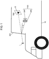
- FIG. 1 is a schematic diagram illustrating a cross-section of a movable vehicle equipped with a head-up display in accordance with a first exemplary embodiment.
- head-up display 100 is installed in a dashboard at the driver's seat side of automobile 10.
- Head-up display 100 is configured by display unit 200 and controller 240.
- Controller 240 controls an image display operation of display unit 200.
- Display unit 200 displays an image. Images to be displayed include various kinds of information such as, for example, a road navigation, a distance to a vehicle in front, a residual battery capacity, and a current travelling speed.
- the image displayed by display unit 200 is reflected by windshield 400 to be guided to eye box 500 of observer D, or a driver of automobile 10, to provide observer D with virtual image I.
- Eye box 500 is an area in which observer D can view full virtual image I without any lacking portion.
- FIG. 2 is a perspective view of the head-up display in accordance with the first exemplary embodiment.
- Display unit 200 includes image display element 210, first wave plate 220, and liquid crystal lens 230.
- Image display element 210 is a liquid crystal display.
- image display element 210 may not be limited to the liquid crystal display, and may be any other display element such as, for example, an organic light-emitting diode display or a plasma display panel (PDP).
- PDP plasma display panel
- Image display element 210 is an element in which left eye pixels for displaying an image for the left eye and right eye pixels for displaying an image for the right eye are alternately arranged.
- Liquid crystal lens 230 is an optical element for stereoscopically displaying an image. Therefore, liquid crystal lens 230 may be substituted by any other optical element that can stereoscopically display an image.
- the optical element may, for example, be a parallax barrier system optical element or a lenticular lens.
- Liquid crystal lens 230 is formed by sealing a liquid crystal in a lens-shaped space and has such a property that its refractive index changes depending on the orientation direction of the liquid crystal.
- the refractive index of liquid crystal lens 230 is changed by adjusting a voltage applied to liquid crystal lens 230 to obtain a desired focal length.
- liquid crystal lens 230 To display a right eye virtual image from the right eye pixels of image display element 210 and a left eye virtual image from the left eye pixels of image display element 210, liquid crystal lens 230 includes lenses each of which is disposed so as to be tilted at a specified angle with respect to the arrangement direction of the pixels of image display element 210.
- Liquid crystal lens 230 including the lenses disposed to be tilted in this manner can prevent generation of a moire pattern which would otherwise be generated due to interference between the pixels of image display element 210 and the arrangement pitches of the lenses of liquid crystal lens 230.
- orientation direction of the liquid crystal molecules in liquid crystal lens 230 may also be aligned along the tilt of the lenses of liquid crystal lens 230 to prevent reduction of the brightness.
- First wave plate 220 is disposed between image display element 210 and liquid crystal lens 230.
- First wave plate 220 may be a half-wave plate.
- First wave plate 220 rotates the polarization direction of the light output from image display element 210 to the arrangement direction of liquid crystal lens 230.
- Reduction of the brightness can be suppressed by first wave plate 220 rotating the polarization direction of the light output from image display element 210 to the arrangement direction of liquid crystal lens 230.
- First wave plate 220 may not be tilted so as to accurately coincide with the arrangement direction of liquid crystal lens 230, but may be tilted at least slightly from the arrangement direction of the pixels of image display element 210 to suppress reduction of the brightness.
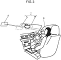
- FIG. 3 is a diagram illustrating a relationship among left eye virtual image IL viewed by the left eye of observer D, right eye virtual image IR viewed by the right eye of observer D and stereo image S.
- virtual images I of parallax images, or left eye virtual image IL and right eye virtual image IR are displayed at a specified position.
- Observer D viewing left eye virtual image IL and right eye virtual image IR perceives that stereo image S, which is a fused image obtained by stereoscopically viewing these virtual images, exists at a position farther than the specified position.
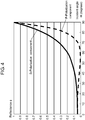
- FIG. 4 is a graph showing polarized light reflection characteristics of the windshield.
- the horizontal axis indicates incident angle ⁇ i (degrees), and the vertical axis indicates reflectance ⁇ .
- the solid line indicates an S-polarization component at incident angle ⁇ i, and the dotted line indicates a P-polarization component at incident angle ⁇ i.
- incident angle ⁇ i is an angle made by a light ray output from the center of display unit 200 and a perpendicular of windshield 400.
- Incident angle ⁇ i is determined by the arrangement of display unit 200, the tilt of windshield 400 and the position of the viewpoint of observer D. As shown in FIG.
- the reflectance ⁇ for the P-polarization component becomes as low as 0.05 or less when incident angle ⁇ i becomes 20 degrees or more.
- incident angle ⁇ i in the vicinity of 60 degrees becomes the Brewster's angle, at which reflectance ⁇ for the P-polarization component becomes 0 (zero).
- Brightness of the light incident on observer D becomes higher as reflectance ⁇ of windshield 400 becomes higher. Accordingly, it can be said that with respect to a light ray output from display unit 200, the brightness of the light incident on observer D increases as the S-polarization component increases.
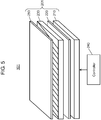
- FIG. 5 is a perspective view of another head-up display in accordance with the first exemplary embodiment.
- Head-up display 101 is configured by display unit 201 and controller 240.
- Display unit 201 includes image display element 210, first wave plate 220, liquid crystal lens 230, and second wave plate 250.
- the configuration of head-up display 101 is different from that of head-up display 100 in that second wave plate 250 is added. In other words, the configuration of head-up display 101 is the same as that of head-up display 100 except for second wave plate 250.
- Second wave plate 250 is a half-wave plate. Second wave plate 250 is rotated so as to increase the S-polarization component of the light output from liquid crystal lens 230.
- the brightness of the light incident on observer D can be made higher by rotating second wave plate 250.
- Polarized sunglasses reduce transmission of the S-polarization component. Accordingly, when second wave plate 250 is rotated so as to increase the S-polarization component of the light output from liquid crystal lens 230, the S-polarization component of the light output from windshield 400 is reduced by the polarized sunglasses. Therefore, when observer D wears polarized sunglasses, the brightness of the light incident on observer D reduces, so that visibility of virtual image I reduces.
- second wave plate 250 may be rotated so that the S-polarization component and the P-polarization component of the light output from liquid crystal lens 230 become in the ratio 1:1.
- a head-up display in accordance with the present exemplary embodiment includes: a controller that controls display of an image; an image display element in which right eye pixels for displaying a right eye virtual image and left eye pixels for displaying a left eye virtual image are alternately arranged; an optical system including optical elements which are arranged at specified intervals, each of the optical elements being disposed so as to be tilted at a specified angle with respect to an arrangement direction of the pixels of the image display element to divide output light of the image display element into a direction toward a right eye and a direction toward a left eye; and a first wave plate disposed between the image display element and the optical system to rotate a polarization direction of the output light of the image display element with respect to the arrangement direction of the pixels of the image display element.
- the first wave plate rotates the polarization direction by an angle which is approximately the same as the specified angle at which the optical system is tilted.
- the head-up display in accordance with the present exemplary embodiment may include a second wave plate disposed at a position in a direction in which light is output from the optical system.
- the second wave plate may rotate the polarization direction of the light output from the optical system so as to increase the S-polarization component.
- the second wave plate may rotate the polarization direction of the light output from the optical system so that the S-polarization component and the P-polarization component become approximately the same in ratio as each other.
- the brightness of the light incident on observer D can be increased when observer D is wearing polarized sunglasses.
- head-up display 102 in accordance with the second exemplary embodiment will be described mainly regarding the points which are different from head-up display 100 described in the first exemplary embodiment.
- the polarization state of the light output from the second wave plate 250 is the same in both of the case in which observer D wears polarized sunglasses and the case in which observer D does not wear polarized sunglasses.
- such a head-up display that can change the brightness of the light output from the head-up display so as to be different between the case in which observer D wears polarized sunglasses and the case in which observer D does not wear polarized sunglasses.
- FIG. 6 is a perspective view of a head-up display in accordance with the second exemplary embodiment.
- head-up display 102 is configured by display unit 202, controller 240, and switch 270.
- Display unit 202 includes image display element 210, first wave plate 220, liquid crystal lens 230, and polarization conversion element 260.
- the configuration of head-up display 102 is different from the configuration of head-up display 100 of the first exemplary embodiment in that polarization conversion element 260 and switch 270 are added. That is, the configuration of head-up display 102 is the same as the configuration of head-up display 100 except for polarization conversion element 260 and switch 270.
- Polarization conversion element 260 may, for example, be a twisted nematic liquid crystal element.
- the twisted nematic liquid crystal element rotates a polarization direction of light passing through it by 90 degrees when a voltage is applied.
- Switch 270 is disposed at such a position that observer D in automobile 10 can turn on or off switch 270. Observer D may turn off switch 270 when observer D is not wearing polarized sunglasses, and may turn on switch 270 when observer D is wearing polarized sunglasses.
- Controller 240 detects the state of switch 270. Controller 240 applies a voltage to polarization conversion element 260 when switch 270 is in the turned-on state, and does not apply the voltage to polarization conversion element 260 when switch 270 is in the turned-off state.
- the polarization characteristic of polarization conversion element 260 is set so as to increase the S-polarization component transmitting through polarization conversion element 260 when no voltage is applied to polarization conversion element 260. As a result, the polarized light reflection characteristics of the light reflected from windshield 400 increase in S-polarization component.
- the polarization characteristic of polarization conversion element 260 is set to rotate the polarization direction of light transmitting through polarization conversion element 260 by 90 degrees so as to increase the P-polarization component transmitting through polarization conversion element 260 when a voltage is applied to polarization conversion element 260. As a result, the polarized light reflection characteristics of the light reflected from windshield 400 increase in P-polarization component.
- polarization conversion element 260 rotates the polarization direction of the light transmitting through it by 90 degrees when a voltage is applied to polarization conversion element 260
- polarization conversion element 260 may not rotate the polarization direction by 90 degrees.
- Polarization conversion element 260 may rotate the polarization direction of the light transmitting through it by an angle in a range larger than 0 degrees and equal to or smaller than 90 degrees.
- a voltage is applied to polarization conversion element 260 when observer D is wearing polarized sunglasses
- the present disclosure is not limited to this.
- a voltage may be applied to polarization conversion element 260 when observer D is not wearing polarized sunglasses.
- a switch is used to specify whether or not observer D is wearing polarized sunglasses
- the present disclosure is not limited to this.
- it may be configured such that one of various sensors such as, for example, a camera provided within automobile 10, automatically detects whether or not observer D is wearing polarized sunglasses.
- a head-up display in accordance with the present exemplary embodiment includes: a controller that controls display of an image; an image display element in which right eye pixels for displaying a right eye virtual image and left eye pixels for displaying a left eye virtual image are alternately arranged; an optical system including optical elements which are arranged at specified intervals, each of the optical elements being disposed so as to be tilted at a specified angle with respect to an arrangement direction of the pixels of the image display element to divide output light of the image display element into a direction toward a right eye and a direction toward a left eye; a first wave plate disposed between the image display element and the optical system to rotate a polarization direction of the output light of the image display element with respect to the arrangement direction of the pixels of the image display element; and a polarization conversion element disposed at a position in a direction in which light is output from the optical system.
- the controller controls application of a voltage to the polarization conversion element.
- the polarization conversion element is set to transmit the light output from the optical system so that the S-polarization component increases when no voltage is applied and that the P-polarization component increases when a voltage is applied.
- first and second exemplary embodiments have been described as examples of techniques according to the present disclosure.
- the techniques according to the present disclosure are not limited to the above-described exemplary embodiments, and may be applied to other exemplary embodiments in which modifications, substitutions, additions, and/or omissions are made as appropriate.
- the components described in the above first and second exemplary embodiments may be appropriately combined to configure a new exemplary embodiment.
- head-up displays each using a windshield have been described in the above exemplary embodiments, the present disclosure is not limited to the above-described head-up displays.
- the present disclosure can be applied to such a head-up display that is provided in its optical path with a mirror having a positive power or a convex lens to display a virtual image.
- the display unit is not limited to the configuration as described in the above exemplary embodiments.
- the display unit may include the optical system for forming a virtual image.
- the present disclosure is applicable to a head-up display capable of displaying a stereo image that can be seen by the naked eye, and to a movable vehicle equipped with the head-up display.
Landscapes
- Physics & Mathematics (AREA)
- General Physics & Mathematics (AREA)
- Optics & Photonics (AREA)
- Engineering & Computer Science (AREA)
- Multimedia (AREA)
- Signal Processing (AREA)
- Instrument Panels (AREA)
- Liquid Crystal (AREA)
- Stereoscopic And Panoramic Photography (AREA)
- Testing, Inspecting, Measuring Of Stereoscopic Televisions And Televisions (AREA)
Applications Claiming Priority (2)
| Application Number | Priority Date | Filing Date | Title |
|---|---|---|---|
| JP2014196562 | 2014-09-26 | ||
| PCT/JP2015/002897 WO2016047009A1 (fr) | 2014-09-26 | 2015-06-10 | Affichage tête haute et corps mobile |
Publications (2)
| Publication Number | Publication Date |
|---|---|
| EP3200005A1 true EP3200005A1 (fr) | 2017-08-02 |
| EP3200005A4 EP3200005A4 (fr) | 2017-11-01 |
Family
ID=55580565
Family Applications (1)
| Application Number | Title | Priority Date | Filing Date |
|---|---|---|---|
| EP15843831.7A Withdrawn EP3200005A4 (fr) | 2014-09-26 | 2015-06-10 | Affichage tête haute et corps mobile |
Country Status (4)
| Country | Link |
|---|---|
| US (1) | US20160349507A1 (fr) |
| EP (1) | EP3200005A4 (fr) |
| JP (1) | JPWO2016047009A1 (fr) |
| WO (1) | WO2016047009A1 (fr) |
Cited By (1)
| Publication number | Priority date | Publication date | Assignee | Title |
|---|---|---|---|---|
| TWI739644B (zh) * | 2020-10-29 | 2021-09-11 | 大陸商業成科技(成都)有限公司 | 增強現實抬頭顯示器 |
Families Citing this family (17)
| Publication number | Priority date | Publication date | Assignee | Title |
|---|---|---|---|---|
| JP2017127396A (ja) * | 2016-01-18 | 2017-07-27 | キヤノン株式会社 | 表示システム、眼用装着具、および表示システムの制御方法 |
| JP6297238B1 (ja) | 2016-04-26 | 2018-03-20 | 京セラ株式会社 | 車両用表示装置 |
| US10234684B2 (en) * | 2016-09-15 | 2019-03-19 | Denso Corporation | Projection member, head up display device, and polarized sunglasses |
| FR3064080B1 (fr) * | 2017-03-17 | 2020-03-06 | Valeo Comfort And Driving Assistance | Afficheur tete haute adapte au port de lunettes polarisantes |
| CN110730924A (zh) | 2017-04-06 | 2020-01-24 | Lg电子株式会社 | 车辆用平视显示装置 |
| US10365483B2 (en) * | 2017-05-23 | 2019-07-30 | Visteon Global Technologies, Inc. | Adjusting a head-up display (HUD) based on polarization |
| US10598927B2 (en) * | 2017-06-08 | 2020-03-24 | Visteon Global Technologies, Inc. | Detecting polarization of a viewer's eyewear |
| JP6924637B2 (ja) | 2017-07-05 | 2021-08-25 | 京セラ株式会社 | 3次元表示装置、3次元表示システム、移動体、および3次元表示方法 |
| CN107479199B (zh) * | 2017-08-04 | 2021-01-26 | 京东方科技集团股份有限公司 | 抬头显示装置及系统 |
| JPWO2019177027A1 (ja) * | 2018-03-13 | 2021-03-25 | 日本化薬株式会社 | 映像投射装置及びヘッドアップディスプレイ装置 |
| EP3813367A4 (fr) * | 2018-06-25 | 2022-08-10 | Kyocera Corporation | Système d'affichage tridimensionnel, élément optique, procédé d'installation, procédé de commande, et corps mobile |
| CN112424672B (zh) * | 2018-07-27 | 2022-10-25 | 京瓷株式会社 | 显示装置、平视显示器以及移动体 |
| JP7188981B2 (ja) | 2018-11-05 | 2022-12-13 | 京セラ株式会社 | 3次元表示装置、3次元表示システム、ヘッドアップディスプレイ、及び移動体 |
| DE102018221797A1 (de) * | 2018-12-14 | 2020-06-18 | Volkswagen Aktiengesellschaft | Benutzerschnittstelle eines Fahrzeugs und Verfahren zur Konfiguration und Steuerung der Benutzerschnittstelle |
| JP7127590B2 (ja) * | 2019-03-26 | 2022-08-30 | 株式会社Jvcケンウッド | 虚像表示装置 |
| DE102019217703A1 (de) * | 2019-11-18 | 2021-06-02 | Volkswagen Aktiengesellschaft | Fahrzeugsitz |
| DE102020121647A1 (de) * | 2020-08-18 | 2022-02-24 | Bayerische Motoren Werke Aktiengesellschaft | Waveguide-Displayanordnung für eine 3D-Blickfeldanzeigevorrichtung in einem Fahrzeug und Verfahren zu deren Betrieb |
Family Cites Families (19)
| Publication number | Priority date | Publication date | Assignee | Title |
|---|---|---|---|---|
| JP2908300B2 (ja) * | 1995-12-12 | 1999-06-21 | 日本電気株式会社 | 立体表示装置 |
| JP3380132B2 (ja) * | 1996-03-15 | 2003-02-24 | シャープ株式会社 | 画像表示装置 |
| ATE552478T1 (de) * | 2004-06-03 | 2012-04-15 | Making Virtual Solid L L C | Navigationsanzeigeverfahren und vorrichtung für unterwegs unter verwendung eines head-up-displays |
| JP4934975B2 (ja) * | 2005-03-17 | 2012-05-23 | エプソンイメージングデバイス株式会社 | 画像表示装置 |
| JP4955967B2 (ja) * | 2005-07-19 | 2012-06-20 | エプソンイメージングデバイス株式会社 | ヘッドアップディスプレイシステム |
| DE102006017666A1 (de) * | 2006-04-12 | 2007-11-08 | Siemens Ag | Anzeigevorrichtung, bei der die Position oder Geometrie der wahrnehmbaren Anzeige mittels eines Motors verstellbar ist |
| DE102008004631A1 (de) * | 2008-01-16 | 2009-07-23 | Robert Bosch Gmbh | Cominer HUD mit Laserprojekten und spezieller RGB-Beschichtung |
| JP2010113197A (ja) * | 2008-11-07 | 2010-05-20 | Nippon Seiki Co Ltd | ヘッドアップディスプレイ装置 |
| US20110102562A1 (en) * | 2009-11-03 | 2011-05-05 | PV Omega, LLC | Multi-spectral stereographic display system with additive and subtractive techniques |
| US20110102563A1 (en) * | 2009-11-03 | 2011-05-05 | Johnson Jr Robert L | Multi-spectral stereographic display system |
| JP2011107589A (ja) * | 2009-11-20 | 2011-06-02 | Sony Corp | 立体表示装置 |
| KR101729682B1 (ko) * | 2010-11-04 | 2017-04-25 | 삼성디스플레이 주식회사 | 광학 유닛 및 이를 포함하는 표시 장치 |
| US8767305B2 (en) * | 2011-08-02 | 2014-07-01 | Google Inc. | Method and apparatus for a near-to-eye display |
| JP6027727B2 (ja) * | 2011-09-09 | 2016-11-16 | 矢崎総業株式会社 | 車両用表示装置 |
| AU2012318987A1 (en) * | 2011-10-05 | 2014-03-20 | Alcon Research, Ltd. | Surgical heads-up display that is adjustable in a three- dimensional field of view |
| JP2013218133A (ja) * | 2012-04-10 | 2013-10-24 | Sharp Corp | 液晶レンズおよび立体表示装置 |
| JP2014150304A (ja) * | 2013-01-31 | 2014-08-21 | Nippon Seiki Co Ltd | 表示装置及びその表示方法 |
| US20140267667A1 (en) * | 2013-03-14 | 2014-09-18 | Valve Corporation | Outward facing camera system with identical camera and eye image picture perspective |
| US20150165906A1 (en) * | 2013-12-18 | 2015-06-18 | Hyundai Motor Company | Display apparatus and method for vehicle |
-
2015
- 2015-06-10 EP EP15843831.7A patent/EP3200005A4/fr not_active Withdrawn
- 2015-06-10 WO PCT/JP2015/002897 patent/WO2016047009A1/fr not_active Ceased
- 2015-06-10 JP JP2016549900A patent/JPWO2016047009A1/ja active Pending
-
2016
- 2016-08-09 US US15/232,600 patent/US20160349507A1/en not_active Abandoned
Cited By (1)
| Publication number | Priority date | Publication date | Assignee | Title |
|---|---|---|---|---|
| TWI739644B (zh) * | 2020-10-29 | 2021-09-11 | 大陸商業成科技(成都)有限公司 | 增強現實抬頭顯示器 |
Also Published As
| Publication number | Publication date |
|---|---|
| JPWO2016047009A1 (ja) | 2017-07-13 |
| WO2016047009A1 (fr) | 2016-03-31 |
| EP3200005A4 (fr) | 2017-11-01 |
| US20160349507A1 (en) | 2016-12-01 |
Similar Documents
| Publication | Publication Date | Title |
|---|---|---|
| EP3200005A1 (fr) | Affichage tête haute et corps mobile | |
| EP3128357B1 (fr) | Dispositif d'affichage | |
| EP3125017A1 (fr) | Appareil d'affichage d'images | |
| US10146052B2 (en) | Virtual image display apparatus, head-up display system, and vehicle | |
| US9823470B2 (en) | Vehicle head-up display device | |
| EP2169966B1 (fr) | Appareil et procédé d'affichage autostéréoscopique commutable en 2D/3D | |
| US9678341B2 (en) | Head-up display apparatus | |
| JP6596668B2 (ja) | 虚像表示装置、ヘッドアップディスプレイシステム、及び乗物 | |
| CN112074770A (zh) | 可调整的三维增强现实平视显示器 | |
| CN104395128B (zh) | 车辆用信息显示装置 | |
| KR102384718B1 (ko) | 허상 표시 장치 | |
| EP3835848B1 (fr) | Affichage " tête haute | |
| WO2018142610A1 (fr) | Dispositif d'affichage stéréoscopique et affichage intégré | |
| JPWO2017170702A1 (ja) | ヘッドアップディスプレイ装置 | |
| US11092804B2 (en) | Virtual image display device | |
| US10015480B2 (en) | Three-dimensional (3D) display module, 3D display system and 3D display method | |
| CN219676374U (zh) | 显示装置、抬头显示装置和交通工具 | |
| JP2016534379A (ja) | 防眩スクリーンを備えるデータ表示眼鏡 | |
| US10725294B2 (en) | Virtual image display device | |
| KR20180046567A (ko) | 차량용 헤드 업 디스플레이 제어 장치 및 방법 | |
| KR102687830B1 (ko) | 헤드 업 디스플레이 장치 | |
| CN209297031U (zh) | 抬头显示装置 | |
| JP2024170277A (ja) | 表示装置及び表示システム |
Legal Events
| Date | Code | Title | Description |
|---|---|---|---|
| PUAI | Public reference made under article 153(3) epc to a published international application that has entered the european phase |
Free format text: ORIGINAL CODE: 0009012 |
|
| 17P | Request for examination filed |
Effective date: 20160909 |
|
| AK | Designated contracting states |
Kind code of ref document: A1 Designated state(s): AL AT BE BG CH CY CZ DE DK EE ES FI FR GB GR HR HU IE IS IT LI LT LU LV MC MK MT NL NO PL PT RO RS SE SI SK SM TR |
|
| AX | Request for extension of the european patent |
Extension state: BA ME |
|
| A4 | Supplementary search report drawn up and despatched |
Effective date: 20171002 |
|
| RIC1 | Information provided on ipc code assigned before grant |
Ipc: G02B 27/26 20060101ALI20170926BHEP Ipc: B60R 16/02 20060101ALI20170926BHEP Ipc: H04N 13/04 20060101ALI20170926BHEP Ipc: G03B 35/24 20060101ALI20170926BHEP Ipc: G02B 27/01 20060101AFI20170926BHEP Ipc: H04N 5/74 20060101ALI20170926BHEP |
|
| DAV | Request for validation of the european patent (deleted) | ||
| DAX | Request for extension of the european patent (deleted) | ||
| STAA | Information on the status of an ep patent application or granted ep patent |
Free format text: STATUS: THE APPLICATION IS DEEMED TO BE WITHDRAWN |
|
| 18D | Application deemed to be withdrawn |
Effective date: 20180501 |