EP3125264B1 - Dispositif de commutation de distribution d'énergie électrique et procédé de coupure d'un courant d'alimentation électrique - Google Patents
Dispositif de commutation de distribution d'énergie électrique et procédé de coupure d'un courant d'alimentation électrique Download PDFInfo
- Publication number
- EP3125264B1 EP3125264B1 EP15178554.0A EP15178554A EP3125264B1 EP 3125264 B1 EP3125264 B1 EP 3125264B1 EP 15178554 A EP15178554 A EP 15178554A EP 3125264 B1 EP3125264 B1 EP 3125264B1
- Authority
- EP
- European Patent Office
- Prior art keywords
- electric power
- power distribution
- current
- surge arrester
- breaking
- Prior art date
- Legal status (The legal status is an assumption and is not a legal conclusion. Google has not performed a legal analysis and makes no representation as to the accuracy of the status listed.)
- Active
Links
Images


Classifications
-
- H—ELECTRICITY
- H01—ELECTRIC ELEMENTS
- H01H—ELECTRIC SWITCHES; RELAYS; SELECTORS; EMERGENCY PROTECTIVE DEVICES
- H01H33/00—High-tension or heavy-current switches with arc-extinguishing or arc-preventing means
- H01H33/60—Switches wherein the means for extinguishing or preventing the arc do not include separate means for obtaining or increasing flow of arc-extinguishing fluid
- H01H33/66—Vacuum switches
- H01H33/664—Contacts; Arc-extinguishing means, e.g. arcing rings
-
- H—ELECTRICITY
- H01—ELECTRIC ELEMENTS
- H01H—ELECTRIC SWITCHES; RELAYS; SELECTORS; EMERGENCY PROTECTIVE DEVICES
- H01H33/00—High-tension or heavy-current switches with arc-extinguishing or arc-preventing means
- H01H33/02—Details
- H01H33/59—Circuit arrangements not adapted to a particular application of the switch and not otherwise provided for, e.g. for ensuring operation of the switch at a predetermined point in the AC cycle
- H01H33/593—Circuit arrangements not adapted to a particular application of the switch and not otherwise provided for, e.g. for ensuring operation of the switch at a predetermined point in the AC cycle for ensuring operation of the switch at a predetermined point of the AC cycle
-
- H—ELECTRICITY
- H02—GENERATION; CONVERSION OR DISTRIBUTION OF ELECTRIC POWER
- H02B—BOARDS, SUBSTATIONS OR SWITCHING ARRANGEMENTS FOR THE SUPPLY OR DISTRIBUTION OF ELECTRIC POWER
- H02B1/00—Frameworks, boards, panels, desks, casings; Details of substations or switching arrangements
- H02B1/26—Casings; Parts thereof or accessories therefor
-
- H—ELECTRICITY
- H02—GENERATION; CONVERSION OR DISTRIBUTION OF ELECTRIC POWER
- H02B—BOARDS, SUBSTATIONS OR SWITCHING ARRANGEMENTS FOR THE SUPPLY OR DISTRIBUTION OF ELECTRIC POWER
- H02B1/00—Frameworks, boards, panels, desks, casings; Details of substations or switching arrangements
- H02B1/26—Casings; Parts thereof or accessories therefor
- H02B1/28—Casings; Parts thereof or accessories therefor dustproof, splashproof, drip-proof, waterproof or flameproof
-
- H—ELECTRICITY
- H02—GENERATION; CONVERSION OR DISTRIBUTION OF ELECTRIC POWER
- H02B—BOARDS, SUBSTATIONS OR SWITCHING ARRANGEMENTS FOR THE SUPPLY OR DISTRIBUTION OF ELECTRIC POWER
- H02B13/00—Arrangement of switchgear in which switches are enclosed in, or structurally associated with, a casing, e.g. cubicle
-
- H—ELECTRICITY
- H02—GENERATION; CONVERSION OR DISTRIBUTION OF ELECTRIC POWER
- H02H—EMERGENCY PROTECTIVE CIRCUIT ARRANGEMENTS
- H02H3/00—Emergency protective circuit arrangements for automatic disconnection directly responsive to an undesired change from normal electric working condition with or without subsequent reconnection ; integrated protection
- H02H3/02—Details
- H02H3/021—Details concerning the disconnection itself, e.g. at a particular instant, particularly at zero value of current, disconnection in a predetermined order
-
- H—ELECTRICITY
- H01—ELECTRIC ELEMENTS
- H01H—ELECTRIC SWITCHES; RELAYS; SELECTORS; EMERGENCY PROTECTIVE DEVICES
- H01H33/00—High-tension or heavy-current switches with arc-extinguishing or arc-preventing means
- H01H33/60—Switches wherein the means for extinguishing or preventing the arc do not include separate means for obtaining or increasing flow of arc-extinguishing fluid
- H01H33/66—Vacuum switches
-
- H—ELECTRICITY
- H01—ELECTRIC ELEMENTS
- H01H—ELECTRIC SWITCHES; RELAYS; SELECTORS; EMERGENCY PROTECTIVE DEVICES
- H01H9/00—Details of switching devices, not covered by groups H01H1/00 - H01H7/00
- H01H9/54—Circuit arrangements not adapted to a particular application of the switching device and for which no provision exists elsewhere
- H01H9/56—Circuit arrangements not adapted to a particular application of the switching device and for which no provision exists elsewhere for ensuring operation of the switch at a predetermined point in the AC cycle
- H01H9/563—Circuit arrangements not adapted to a particular application of the switching device and for which no provision exists elsewhere for ensuring operation of the switch at a predetermined point in the AC cycle for multipolar switches, e.g. different timing for different phases, selecting phase with first zero-crossing
Definitions
- the present invention relates to electric power distribution switchgears and to methods of breaking electric power currents.
- a circuit breaker can be an automatically operated electrical switch designed to protect an electrical circuit from damage caused by overload or short circuit. Its basic function is to detect a fault condition and interrupt current flow. Unlike a fuse, which operates once and then must be replaced, a circuit breaker can be reset (either manually or automatically) to resume normal operation.
- Circuit breakers are also increasingly used to switch loads on and off.
- Circuit breakers are made in varying sizes, from small devices that protect an individual household appliance up to large switchgear designed to protect high voltage circuits feeding an entire city.
- the circuit breaker contacts must carry the load current without excessive heating, and must also withstand the heat of the arc produced when interrupting (opening) the circuit.
- Contacts may be made of copper or copper alloys, such as e.g. copper-tungsten alloys, silver alloys and other highly conductive materials. Service life of the contacts is limited by the erosion of contact material due to arcing while interrupting the current. Miniature and moulded-case circuit breakers are usually discarded when the contacts have worn, but power circuit breakers and high-voltage circuit breakers have replaceable contacts.
- US 4 628 393 describes an electric power distribution system according to the preamble of claim 1 and a method according to the preamble of claim 11 for interrupting an inductive load in a three-phase, high voltage network by means of a switch having a quick dielectric recovery, in particular a vacuum switch, in which two of the three vacuum switche3s, having a quick dielectric recovery, open at least 1/3 of a cycle of the network frequency later than the first vacuum switch, in order to prevent high over-voltages, caused by virtual chopping.
- Vacuum circuit breakers are capable of interrupting high frequency currents and therefore there is a certain possibility that multiple re-ignitions may appear at the interruption, especially where there are purely or partly inductive loads.
- Synchronization of vacuum circuit breakers have been studied extensively and there exist a number of synchronization techniques, but still they are generally limited to certain operation cases. Synchronization of vacuum circuit breakers can be designed to avoid transients caused by re-ignitions and virtual current chopping during circuit breaker opening. These transients are the worst transients due to their amplitudes, steepness, and, not at least, frequency.
- the present invention is based on the realization that while the synchronization techniques have generally good performance, it is still also difficult to take care of all aspects of a breaking process since different phenomena may occur, which may have to be taken care of in different manners. Thus, different synchronization techniques have different performances in different environments, where different phenomena take place during the breaking process.
- An object of the present invention is to provide an electric power distribution switchgear, which comprises a synchronized vacuum circuit breaker, but which still is capable of alleviating, or at least mitigating, problems with transient over voltages while performing a breaking process.
- an electric power distribution system comprises an electric power distribution switchgear, an electric power grind and an electric power equipment, wherein the electric power distribution switchgear is connected between the electric power grid and the electric power equipment, constituting pure, or partwise, inductive load.
- the electric power equipment is a transformer of a three-phase power system.
- the electric power distribution switchgear comprises
- the synchronization of the vacuum circuit breaker causes the vacuum circuit breaker to break each phase current at a phase angle, at which the phase current is different from zero.
- the synchronized vacuum circuit breaker starts opening of its contacts of each phase approximately at a phase angle, at which the phase voltage has a zero crossing, or thereafter. For a pure inductive load, this means that the contacts start opening at about one fourth of a period, or less, from a current zero crossing. For a 50 Hz three-phase system, the contacts may be separated at about 1, 2, 3, 4, or 5 ms before a zero current crossing.
- the contact separation of the switching apparatus should be started at a phase angle of the current to ensure an arcing time before the current is interrupted, which arcing time is long enough to make the contact separation large enough to withstand the recovery voltage after the current is interrupted and this way preventing re-ignitions and re-strikes. Too short arcing time may result in re-ignition while too long arcing time may result in wear and tear of the contacts of the switching apparatus.
- a suitable arcing time may be from about 0.5 ms to a time corresponding to about one fourth of a period of the current through the switching apparatus.
- transient over-voltages caused by said re-ignition may have a first frequency content and the transients caused by current chopping of the load current at the breaking may have a second frequency content, which is lower or much lower range than the first frequency contents.
- transients caused by re-ignition are complex to handle by traditional protecting devices such as surge arrester arrangements, as they need to be placed very close to the equipment they are intended to protect, whereas surge arrester arrangements can easily be designed and configured to handle the lower frequency (e.g. kHz region) slowly varying over-voltages caused by the current chopping of the current at the breaking.
- the lower frequency over-voltages allows a location of the surge arrester arrangement, which is remote from the equipment it is intended to protect. By remote is here meant a selected distance away from the equipment and not in absolute proximity thereto.
- current chopping is here understood an interruption of an alternating current when the arc is extinguished, which is before, or slightly before, its neutral zero.
- the surge arrester arrangement does not need to be located in direct connection with the electric power equipment, which it protects, but can be located remote from there as mentioned above. This is due to the lower frequencies of the transient over voltages caused by the current chopping (typically in the kHz range).
- the electric power distribution switchgear comprises an enclosure having compartments housing both the switching apparatus and the surge arrester arrangement, where the surge arrester arrangement is connected to the electric power equipment side of the power distribution switchgear in order to handle the slowly varying over-voltages caused by the current chopping at the breaking of the current.
- both the switching apparatus and the surge arrester arrangement can be placed in a common cabinet.
- the electrodes of the synchronized vacuum switching apparatus may be arranged in a vacuum chamber, parts of, or the entire, synchronized vacuum switching apparatus, and optionally also the surge arrester arrangement, can be arranged in a sealed gas tight encapsulation, which may comprise a dielectric insulation medium.
- the dielectric insulation medium may comprise an insulating gas, and preferably a gas that has a GWP of less than 2300, and preferably less than 150.
- a suitable dielectric insulation gas may be an organofluorine compound selected from the group consisting of: a fluorether, an oxirane, a fluoramine, a fluoroketone, a fluoroolefin, and mixtures and/or decomposition products thereof.
- the synchronized vacuum switching apparatus is a multi-pole apparatus, wherein all phases are interrupted simultaneously.
- a multipole apparatus of the above kind may be usable to interrupt the current in one phase initially and to interrupt all other phases at a time which is less than half a period later (with respect to the alternating current used).
- the second interruption may be initiated lass than 10 ms, such as e.g. at about 5 ms, later than the first interruption, given a 50 Hz system.
- a method of breaking an electric power current in an electric power distribution switchgear is provided.
- the current to an electric power equipment is broken by a synchronized vacuum switching apparatus using a technique synchronized with the current through the switching apparatus (to the electric power equipment) so as to avoid re-ignition during the breaking and thus any transient over-voltages caused by such re-ignition.
- transients caused by current chopping of the current at the breaking is handled by a surge arrester arrangement connected to the electric power equipment, the surge arrester arrangement being designed and configured to only handle the over-voltages caused by the current chopping, which are slowly varying (e.g. in the kHz range) as compared to the other transients, which have higher frequency and which are avoided by the synchronized breaking.
- the transients handled by the surge arrester arrangement are more easily handled by the surge arrester arrangement (as compared to the other transients) due to their more slowly varying voltage levels, and as a result, the surge arrester arrangement does not have to be arranged in direct connection with the electric power equipment to be protected, but can be arranged at a selected distance from it such as within a cabinet of the electric power distribution switchgear, which then houses both the synchronized vacuum switching apparatus and the surge arrester arrangement.
- the electric power distribution switchgear disclosed above may be a medium voltage device having a rated voltage of 72 kV or less, and consequently, the electric power equipment and the electric power grid, to which the electric power equipment is connected, have also voltage ratings in the medium voltage range.
- Fig. 1 illustrates, schematically, in a circuit diagram, a three-phase electric power distribution system comprising an electric power distribution switchgear 11 according to an embodiment.
- the electric power distribution system comprises an electric power equipment 12 connected via power line 13, the electric power distribution switchgear 11 and power line 14 to an electric power grid.
- the electric power equipment 12 may constitute an inductive load 15, and may, for example, comprise a transformer.
- the electric power distribution switchgear 11 comprises a synchronized vacuum circuit breaker 16 for breaking the current between the power lines 13, 14, and a surge arrester arrangement 17 for protecting the electric power equipment 12 from some kind of transients in case of a breaking process is effectuated.
- Synchronization of the vacuum circuit breaker 16 with the inductive current through it during a breaking process is used to avoid a first class of transients, namely transients which may occur from re-ignition and virtual current chopping during the breaking. These transients are complex and costly to handle with surge arrester devices, but can be partly or entirely avoided by a proper synchronization of the vacuum circuit breaker 16 during the breaking process.
- the synchronization of the vacuum circuit breaker 16 may cause the vacuum circuit breaker contacts to open at a phase angle of the current which allows an arcing time of about 1, 2, 3, 4, or 5 ms for a 50 Hz system before the current is interrupted by the current chopping.
- the synchronized vacuum circuit breaker contacts open approximately at a phase angle, at which the phase voltage has a zero crossing, or therafter.
- a current zero crossing i.e. at maximum current
- the zero current crossing such as at about 1, 2, 3, 4, or 5 ms before the zero current crossing in a 50 Hz system.
- the synchronization does not handle transients caused by current chopping of the load current at the breaking (that is, the instantaneous cutting of the current before the natural zero crossing), but the over voltage transients caused by this have lower to much lower frequency content than the transients which are handled - and avoided - using the synchronization.
- the over-voltage transients have a rather low frequency, such as e.g. in the kHz range, and can easily and readily be handled by a surge arrester arrangement, which also does not have to be located in direct connection with the electric power equipment 12 it protects, but can be arranged remote from there, e.g. even at the other end of the power line 13.
- an electric power distribution switchgear 11 which uses a synchronized vacuum circuit breaker 16 for breaking the current while avoiding any transient over-voltages caused by re-ignition (and optionally by virtual current chopping) during the breaking combined with a surge arrester arrangement 17 for handling more slowly varying transient over-voltages caused by the current chopping of the load current at the breaking.
- the latter can easily be achieved by a surge arrester arrangement 17, which can even be located remote from the electric power equipment 12.
- the surge arrester arrangement 17 can advantageously be located together with the synchronized vacuum circuit breaker 16 in a common housing.
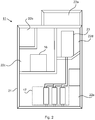
- Fig. 2 illustrates, schematically, in an end view, such an embodiment of the electric power distribution switchgear of Fig. 1 .
- the electric power distribution switchgear 11 comprises an encapsulation, casing, or housing 21 with different compartments 22a-e.
- Compartment 22a is a compact gas duct channel
- compartment 22b is a low voltage compartment
- compartment 22c is a circuit-breaker compartment
- compartment 22d is a busbar compartment
- compartment 22e is a surge arrester compartment.
- the synchronized vacuum circuit breaker 16 may be arranged in compartment 22c
- the surge arrester arrangement 17 may be arranged in compartment 22e
- a busbar device 23 may be arranged in compartment 22d. Note that while the surge arrester arrangement 17 may be located remote from the electric power equipment 12 (see Fig. 1 ), it has still to be connected to the power line 13, e.g. via the busbar device 23 in compartment 22d.
- the housing 21, or at least the part of it, which houses parts of, or the entire, synchronized vacuum circuit breaker 16, may comprise a sealed gas tight encapsulation.
- a dielectric insulation medium such as air or a dielectric insulation gas comprising an organofluorine compound selected from the group consisting of: a fluorether, an oxirane, a fluoramine, a fluoroketone, a fluoroolefin, and mixtures and/or decomposition products thereof, may be present in the sealed gas tight encapsulation.
- Fig. 3 illustrates, schematically, in a flow scheme, an embodiment of a method of breaking an electric power current in an electric power distribution switchgear such as e.g. the one in any of Figs. 1-2 .
- the current to the electric power equipment is, in a step 31, broken by a synchronized vacuum switching apparatus using a technique synchronized with the current through the synchronized vacuum switching apparatus so as to avoid re-ignition during the breaking and thus any transient over-voltages caused by such re-ignition.
- the remaining transients which are those low frequency transients caused by current chopping of the load current at the breaking, are, in a step 32, handled by a surge arrester arrangement connected to the electric power equipment, wherein the surge arrester arrangement is designed and configured to only handle such transients caused by the current chopping of the load current at the breaking.
- the slowly varying transient over-voltages caused by the current chopping at the breaking may be handled by a surge arrester arrangement, which can even be arranged remote from the electric power equipment, such as e.g. together with the synchronized vacuum switching apparatus in a common enclosure of the electric power distribution switchgear.
Landscapes
- Engineering & Computer Science (AREA)
- Power Engineering (AREA)
- Driving Mechanisms And Operating Circuits Of Arc-Extinguishing High-Tension Switches (AREA)
- High-Tension Arc-Extinguishing Switches Without Spraying Means (AREA)
- Gas-Insulated Switchgears (AREA)
- Emergency Protection Circuit Devices (AREA)
Claims (15)
- Système de distribution d'énergie électrique, comprenant un réseau électrique, un appareillage de commutation de distribution d'énergie électrique, et un équipement électrique, dans lequel l'appareillage de commutation de distribution d'énergie électrique (11) est connecté entre le réseau électrique et l'équipement électrique (12), et dans lequel ledit équipement électrique est une charge inductive et l'appareillage de commutation de distribution d'énergie électrique comprend :- un appareil de commutation à vide synchronisée (16) d'une tension nominale adaptée à la tension nominale de l'appareillage de commutation de distribution d'énergie électrique, l'appareil de commutation à vide synchronisée (16) étant configuré pour couper le courant allant audit équipement électrique à l'aide d'une technique synchronisée avec le courant passant par l'appareil de commutation à vide synchronisée (16) pour éviter un réallumage durant la coupure et ainsi toute surtention transitoire causée par un tel réallumage, caractérisé en ce que- l'appareillage de commutation de distribution d'énergie électrique comprend en outre un agencement parafoudre (17) connecté audit équipement électrique, l'agencement parafoudre (17) étant conçu et configuré pour prendre en charge uniquement les effets transitoires causés par un hachage de courant du courant de charge à la coupure.
- Système de distribution d'énergie électrique selon la revendication 1 dans lequel ledit agencement parafoudre (17) est disposé à distance dudit équipement électrique (12).
- Système de distribution d'énergie électrique selon la revendication 1 ou 2 dans lequel ledit appareillage de commutation de distribution d'énergie électrique comprend une enceinte (21) présentant des compartiments (22) qui abritent ledit appareil de commutation à vide synchronisée (16) et ledit agencement parafoudre (17).
- Système de distribution d'énergie électrique selon l'une quelconque des revendications précédentes dans lequel les surtensions transitoires causées par ledit réallumage ont une première fréquence et les effets transitoires causés par un hachage de courant du courant de charge à la coupure ont une seconde fréquence, laquelle est inférieure ou très inférieure à la première fréquence.
- Système de distribution d'énergie électrique selon l'une quelconque des revendications précédentes dans lequel ledit équipement électrique (12) comprend un transformateur.
- Système de distribution d'énergie électrique selon l'une quelconque des revendications précédentes dans lequel ledit appareillage de commutation de distribution d'énergie électrique (11) est un dispositif triphasé et l'agencement parafoudre (17) comprend au moins un parafoudre pour chaque phase.
- Système de distribution d'énergie électrique selon l'une quelconque des revendications précédentes dans lequel ledit appareillage de commutation de distribution d'énergie électrique (11) comprend une encapsulation scellée étanche aux gaz, dans laquelle est disposé ledit appareil de commutation à vide synchronisée (16).
- Système de distribution d'énergie électrique selon la revendication 7, dans lequel un milieu d'isolation diélectrique est présent dans l'encapsulation.
- Système de distribution d'énergie électrique selon la revendication 8, dans lequel le milieu d'isolation diélectrique est un gaz d'isolation diélectrique comprenant un composé organofluoré sélectionné dans le groupe consistant en : un fluoréther, un oxirane, un fluoramine, une fluorocétone, une fluorooléfine, et des mélanges et/ou produits de décomposition de ceux-ci.
- Système de distribution d'énergie électrique selon l'une quelconque des revendications précédentes dans lequel l'appareil de commutation à vide (16) est un rupteur à vide (16), un contacteur à vide, ou un interrupteur coupe-charge à vide.
- Procédé de coupure d'un courant électrique dans un appareillage de commutation de distribution d'énergie électrique (11) connecté entre un réseau électrique et un équipement électrique (12), dans lequel ledit équipement électrique a une charge inductive et le procédé comprend les étapes de :- coupure du courant allant audit équipement électrique par un appareil de commutation à vide synchronisée (16) à l'aide d'une technique synchronisée avec le courant passant par l'appareil de commutation à vide synchronisée (16) pour éviter un réallumage durant la coupure et ainsi toute surtension transitoire causée par un tel réallumage, caractérisé par l'étape de :- prise en charge uniquement des effets transitoires causés par un hachage de courant du courant de charge à la coupure par un agencement parafoudre (17) connecté audit équipement électrique, l'agencement parafoudre étant conçu et configuré pour ne prendre en charge que les effets transitoires causés par ledit hachage de courant.
- Procédé selon la revendication 11 dans lequel ledit agencement parafoudre est diposé à distance dudit équipement électrique (12) à charge inductive.
- Procédé selon la revendication 12 dans lequel ledit agencement parafoudre (17) est disposé avec l'appareil de commutation à vide synchronisée (16) dans une même enceinte (21) dudit appareillage de commutation de distribution d'énergie électrique.
- Procédé selon l'une quelconque des revendications 11 à 13 dans lequel les surtensions transitoires causées par ledit réallumage ont une première fréquence et les effets transitoires causés par un hachage de courant du courant de charge à la coupure ont une seconde fréquence, laquelle est inférieure ou très inférieure à la première fréquence.
- Procédé selon l'une quelconque des revendications 11 à 14, ledit procédé étant exécuté dans un système triphasé et ledit agencement parafoudre comprenant au moins un parafoudre pour chaque phase.
Priority Applications (4)
| Application Number | Priority Date | Filing Date | Title |
|---|---|---|---|
| EP15178554.0A EP3125264B1 (fr) | 2015-07-28 | 2015-07-28 | Dispositif de commutation de distribution d'énergie électrique et procédé de coupure d'un courant d'alimentation électrique |
| CN201680044112.4A CN107851534B (zh) | 2015-07-28 | 2016-06-17 | 电力配电开关柜和电力电流切断方法 |
| PCT/EP2016/063973 WO2017016748A1 (fr) | 2015-07-28 | 2016-06-17 | Appareillage de distribution de puissance électrique et procédé de coupure d'un courant électrique |
| US15/747,832 US10242826B2 (en) | 2015-07-28 | 2016-06-17 | Electric power distribution switchgear and method of breaking an electric power current |
Applications Claiming Priority (1)
| Application Number | Priority Date | Filing Date | Title |
|---|---|---|---|
| EP15178554.0A EP3125264B1 (fr) | 2015-07-28 | 2015-07-28 | Dispositif de commutation de distribution d'énergie électrique et procédé de coupure d'un courant d'alimentation électrique |
Publications (2)
| Publication Number | Publication Date |
|---|---|
| EP3125264A1 EP3125264A1 (fr) | 2017-02-01 |
| EP3125264B1 true EP3125264B1 (fr) | 2018-02-28 |
Family
ID=53724118
Family Applications (1)
| Application Number | Title | Priority Date | Filing Date |
|---|---|---|---|
| EP15178554.0A Active EP3125264B1 (fr) | 2015-07-28 | 2015-07-28 | Dispositif de commutation de distribution d'énergie électrique et procédé de coupure d'un courant d'alimentation électrique |
Country Status (4)
| Country | Link |
|---|---|
| US (1) | US10242826B2 (fr) |
| EP (1) | EP3125264B1 (fr) |
| CN (1) | CN107851534B (fr) |
| WO (1) | WO2017016748A1 (fr) |
Families Citing this family (5)
| Publication number | Priority date | Publication date | Assignee | Title |
|---|---|---|---|---|
| EP3358588A1 (fr) | 2017-02-02 | 2018-08-08 | ABB Schweiz AG | Interrupteur triphasé ayant une commande spécifique aux phases |
| EP3451355A1 (fr) | 2017-08-29 | 2019-03-06 | ABB Schweiz AG | Disjoncteur à vide motorisé |
| US10870967B2 (en) * | 2018-04-20 | 2020-12-22 | Joy Global Surface Mining Inc | Medium voltage room for a mining shovel |
| CN114446705B (zh) * | 2022-02-16 | 2023-08-11 | 广东电网有限责任公司 | 一种同步断路装置 |
| CN117728589B (zh) * | 2024-02-08 | 2024-04-26 | 山西同鑫达电气工程有限公司 | 配电箱用电监测方法、装置、设备及介质 |
Family Cites Families (17)
| Publication number | Priority date | Publication date | Assignee | Title |
|---|---|---|---|---|
| US2246926A (en) * | 1938-11-01 | 1941-06-24 | Westinghouse Electric & Mfg Co | Surge protection for electrical apparatus |
| US4209814A (en) | 1977-10-19 | 1980-06-24 | Gould Inc. | Synchronous circuit breaker |
| US4628393A (en) * | 1977-12-14 | 1986-12-09 | Hazemeijer B.V. | Method for switching in a three-phase high voltage circuit |
| ATE17807T1 (de) * | 1981-08-04 | 1986-02-15 | Yelland Engineering | Elektrisch schaltender ueberspannungsschutz. |
| ES516519A1 (es) * | 1981-11-09 | 1983-08-01 | Gen Electric | "sistema para efectuar la proteccion contra sobretensiones y para suprimir las oscilaciones de tension en un dispositivo electromagnetico". |
| US4922363A (en) * | 1985-10-17 | 1990-05-01 | General Electric Company | Contactor control system |
| US4950854A (en) | 1989-10-31 | 1990-08-21 | Electric Services, Inc. | Vacuum operated circuit breaker apparatus for replacing air-magnetic circuit breaker assemblies |
| JPH08149698A (ja) | 1994-11-16 | 1996-06-07 | Meidensha Corp | 同期保護装置 |
| US5633540A (en) | 1996-06-25 | 1997-05-27 | Lutron Electronics Co., Inc. | Surge-resistant relay switching circuit |
| CA2298583C (fr) | 1998-07-16 | 2004-08-31 | Mitsubishi Denki Kabushiki Kaisha | Appareil de commutation synchrone pour utilisation avec un reseau polyphase |
| GB0411802D0 (en) * | 2004-05-26 | 2004-06-30 | Electro Magnetic Rams Ltd | Switchgear system |
| CN2744041Y (zh) * | 2004-09-24 | 2005-11-30 | 刘羿 | 一种三相节电保护装置 |
| US7576957B2 (en) * | 2006-05-01 | 2009-08-18 | Eaton Corporation | Circuit interrupter including point-on-wave controller and voltage sensors |
| CN101170257B (zh) * | 2007-11-30 | 2010-08-11 | 上海电科电器科技有限公司 | 电涌保护器的后备保护单元 |
| CN201478819U (zh) * | 2009-08-28 | 2010-05-19 | 北京清网华科技有限公司 | 电源防雷箱的电源防雷单元 |
| US8451589B2 (en) * | 2010-06-07 | 2013-05-28 | Abd El & Larson Holdings LLC | Multi-access switchgear assembly |
| EP2509082B1 (fr) * | 2011-04-07 | 2013-07-31 | ABB Technology AG | Bobine haute tension isolée contre les fluides |
-
2015
- 2015-07-28 EP EP15178554.0A patent/EP3125264B1/fr active Active
-
2016
- 2016-06-17 US US15/747,832 patent/US10242826B2/en active Active
- 2016-06-17 CN CN201680044112.4A patent/CN107851534B/zh active Active
- 2016-06-17 WO PCT/EP2016/063973 patent/WO2017016748A1/fr not_active Ceased
Non-Patent Citations (1)
| Title |
|---|
| None * |
Also Published As
| Publication number | Publication date |
|---|---|
| WO2017016748A1 (fr) | 2017-02-02 |
| EP3125264A1 (fr) | 2017-02-01 |
| US10242826B2 (en) | 2019-03-26 |
| US20180226213A1 (en) | 2018-08-09 |
| CN107851534B (zh) | 2019-06-07 |
| CN107851534A (zh) | 2018-03-27 |
Similar Documents
| Publication | Publication Date | Title |
|---|---|---|
| US10242826B2 (en) | Electric power distribution switchgear and method of breaking an electric power current | |
| CN1415130A (zh) | 集成的负载连接器模块 | |
| WO2013127084A1 (fr) | Chambre d'extinction d'arc sous vide à fracture fixe | |
| RU2410788C2 (ru) | Электрический коммутационный аппарат | |
| US6239514B1 (en) | Electric switching device and a method for performing electric disconnection of a load | |
| JPH06335125A (ja) | 開閉装置 | |
| SE1351510A1 (sv) | Anordning för skydd av en elektrisk apparat som matas av ettflerfasnät | |
| CN210780092U (zh) | 消弧消谐装置 | |
| EA021000B1 (ru) | Трансформаторная подстанция | |
| ReddyVenna et al. | Suitability of vacuum circuit breakers for generator switching applications according to dual logo standard IEC/IEEE 62271-37-013 | |
| Elvis et al. | Aspects regarding the controlled switching of the shunt reactors | |
| Telander et al. | Surge limiters for vacuum circuit breakers | |
| Chernoskutov et al. | Analysis of SF6 Circuit Breakers Failures Related to Missing Current Zero-Part I | |
| JP4532735B2 (ja) | 負荷の電気的非接続を実行するための電気スイッチング・デバイスおよび方法 | |
| Urbanek et al. | Vacuum circuit breakers—Promising switching technology for pumped storage power plants up to 450 MVA | |
| Delić et al. | Capacitive current breaking capability estimation for a 145 kV 40 kA GIS circuit breaker | |
| Farag et al. | Guidelines for the application of vacuum contactors | |
| RU2755021C1 (ru) | Генераторный гибридный выключатель | |
| Singh | Switchgear and power system protection | |
| Taylor et al. | Single-phase short-circuit testing of vacuum interrupters for power systems with an effectively earthed neutral | |
| Kokin et al. | Features of controlled switching under normal and emergency operating conditions in medium voltage networks | |
| Rieder | Circuit breakers Physical and engineering problems III-Arc-medium considerations | |
| Schellekens et al. | Impact of vacuum switch-disconnectors on reliability of MV distribution networks | |
| Agarwal | Vacuum interrupter applications in electrical power systems | |
| Harun et al. | DET50083 POWER SYSTEM PROTECTION |
Legal Events
| Date | Code | Title | Description |
|---|---|---|---|
| PUAI | Public reference made under article 153(3) epc to a published international application that has entered the european phase |
Free format text: ORIGINAL CODE: 0009012 |
|
| AK | Designated contracting states |
Kind code of ref document: A1 Designated state(s): AL AT BE BG CH CY CZ DE DK EE ES FI FR GB GR HR HU IE IS IT LI LT LU LV MC MK MT NL NO PL PT RO RS SE SI SK SM TR |
|
| AX | Request for extension of the european patent |
Extension state: BA ME |
|
| RAP1 | Party data changed (applicant data changed or rights of an application transferred) |
Owner name: ABB SCHWEIZ AG |
|
| 17P | Request for examination filed |
Effective date: 20170801 |
|
| RBV | Designated contracting states (corrected) |
Designated state(s): AL AT BE BG CH CY CZ DE DK EE ES FI FR GB GR HR HU IE IS IT LI LT LU LV MC MK MT NL NO PL PT RO RS SE SI SK SM TR |
|
| GRAP | Despatch of communication of intention to grant a patent |
Free format text: ORIGINAL CODE: EPIDOSNIGR1 |
|
| INTG | Intention to grant announced |
Effective date: 20171004 |
|
| GRAS | Grant fee paid |
Free format text: ORIGINAL CODE: EPIDOSNIGR3 |
|
| GRAA | (expected) grant |
Free format text: ORIGINAL CODE: 0009210 |
|
| AK | Designated contracting states |
Kind code of ref document: B1 Designated state(s): AL AT BE BG CH CY CZ DE DK EE ES FI FR GB GR HR HU IE IS IT LI LT LU LV MC MK MT NL NO PL PT RO RS SE SI SK SM TR |
|
| REG | Reference to a national code |
Ref country code: GB Ref legal event code: FG4D Ref country code: CH Ref legal event code: EP |
|
| REG | Reference to a national code |
Ref country code: AT Ref legal event code: REF Ref document number: 974988 Country of ref document: AT Kind code of ref document: T Effective date: 20180315 |
|
| REG | Reference to a national code |
Ref country code: IE Ref legal event code: FG4D |
|
| REG | Reference to a national code |
Ref country code: DE Ref legal event code: R096 Ref document number: 602015008264 Country of ref document: DE |
|
| REG | Reference to a national code |
Ref country code: NL Ref legal event code: MP Effective date: 20180228 |
|
| REG | Reference to a national code |
Ref country code: LT Ref legal event code: MG4D |
|
| REG | Reference to a national code |
Ref country code: AT Ref legal event code: MK05 Ref document number: 974988 Country of ref document: AT Kind code of ref document: T Effective date: 20180228 |
|
| REG | Reference to a national code |
Ref country code: FR Ref legal event code: PLFP Year of fee payment: 4 |
|
| PG25 | Lapsed in a contracting state [announced via postgrant information from national office to epo] |
Ref country code: FI Free format text: LAPSE BECAUSE OF FAILURE TO SUBMIT A TRANSLATION OF THE DESCRIPTION OR TO PAY THE FEE WITHIN THE PRESCRIBED TIME-LIMIT Effective date: 20180228 Ref country code: CY Free format text: LAPSE BECAUSE OF FAILURE TO SUBMIT A TRANSLATION OF THE DESCRIPTION OR TO PAY THE FEE WITHIN THE PRESCRIBED TIME-LIMIT Effective date: 20180228 Ref country code: NO Free format text: LAPSE BECAUSE OF FAILURE TO SUBMIT A TRANSLATION OF THE DESCRIPTION OR TO PAY THE FEE WITHIN THE PRESCRIBED TIME-LIMIT Effective date: 20180528 Ref country code: NL Free format text: LAPSE BECAUSE OF FAILURE TO SUBMIT A TRANSLATION OF THE DESCRIPTION OR TO PAY THE FEE WITHIN THE PRESCRIBED TIME-LIMIT Effective date: 20180228 Ref country code: HR Free format text: LAPSE BECAUSE OF FAILURE TO SUBMIT A TRANSLATION OF THE DESCRIPTION OR TO PAY THE FEE WITHIN THE PRESCRIBED TIME-LIMIT Effective date: 20180228 Ref country code: LT Free format text: LAPSE BECAUSE OF FAILURE TO SUBMIT A TRANSLATION OF THE DESCRIPTION OR TO PAY THE FEE WITHIN THE PRESCRIBED TIME-LIMIT Effective date: 20180228 Ref country code: ES Free format text: LAPSE BECAUSE OF FAILURE TO SUBMIT A TRANSLATION OF THE DESCRIPTION OR TO PAY THE FEE WITHIN THE PRESCRIBED TIME-LIMIT Effective date: 20180228 |
|
| PG25 | Lapsed in a contracting state [announced via postgrant information from national office to epo] |
Ref country code: SE Free format text: LAPSE BECAUSE OF FAILURE TO SUBMIT A TRANSLATION OF THE DESCRIPTION OR TO PAY THE FEE WITHIN THE PRESCRIBED TIME-LIMIT Effective date: 20180228 Ref country code: LV Free format text: LAPSE BECAUSE OF FAILURE TO SUBMIT A TRANSLATION OF THE DESCRIPTION OR TO PAY THE FEE WITHIN THE PRESCRIBED TIME-LIMIT Effective date: 20180228 Ref country code: GR Free format text: LAPSE BECAUSE OF FAILURE TO SUBMIT A TRANSLATION OF THE DESCRIPTION OR TO PAY THE FEE WITHIN THE PRESCRIBED TIME-LIMIT Effective date: 20180529 Ref country code: AT Free format text: LAPSE BECAUSE OF FAILURE TO SUBMIT A TRANSLATION OF THE DESCRIPTION OR TO PAY THE FEE WITHIN THE PRESCRIBED TIME-LIMIT Effective date: 20180228 Ref country code: RS Free format text: LAPSE BECAUSE OF FAILURE TO SUBMIT A TRANSLATION OF THE DESCRIPTION OR TO PAY THE FEE WITHIN THE PRESCRIBED TIME-LIMIT Effective date: 20180228 Ref country code: BG Free format text: LAPSE BECAUSE OF FAILURE TO SUBMIT A TRANSLATION OF THE DESCRIPTION OR TO PAY THE FEE WITHIN THE PRESCRIBED TIME-LIMIT Effective date: 20180528 |
|
| PG25 | Lapsed in a contracting state [announced via postgrant information from national office to epo] |
Ref country code: PL Free format text: LAPSE BECAUSE OF FAILURE TO SUBMIT A TRANSLATION OF THE DESCRIPTION OR TO PAY THE FEE WITHIN THE PRESCRIBED TIME-LIMIT Effective date: 20180228 Ref country code: AL Free format text: LAPSE BECAUSE OF FAILURE TO SUBMIT A TRANSLATION OF THE DESCRIPTION OR TO PAY THE FEE WITHIN THE PRESCRIBED TIME-LIMIT Effective date: 20180228 Ref country code: EE Free format text: LAPSE BECAUSE OF FAILURE TO SUBMIT A TRANSLATION OF THE DESCRIPTION OR TO PAY THE FEE WITHIN THE PRESCRIBED TIME-LIMIT Effective date: 20180228 Ref country code: RO Free format text: LAPSE BECAUSE OF FAILURE TO SUBMIT A TRANSLATION OF THE DESCRIPTION OR TO PAY THE FEE WITHIN THE PRESCRIBED TIME-LIMIT Effective date: 20180228 |
|
| REG | Reference to a national code |
Ref country code: DE Ref legal event code: R097 Ref document number: 602015008264 Country of ref document: DE |
|
| PG25 | Lapsed in a contracting state [announced via postgrant information from national office to epo] |
Ref country code: SM Free format text: LAPSE BECAUSE OF FAILURE TO SUBMIT A TRANSLATION OF THE DESCRIPTION OR TO PAY THE FEE WITHIN THE PRESCRIBED TIME-LIMIT Effective date: 20180228 Ref country code: CZ Free format text: LAPSE BECAUSE OF FAILURE TO SUBMIT A TRANSLATION OF THE DESCRIPTION OR TO PAY THE FEE WITHIN THE PRESCRIBED TIME-LIMIT Effective date: 20180228 Ref country code: DK Free format text: LAPSE BECAUSE OF FAILURE TO SUBMIT A TRANSLATION OF THE DESCRIPTION OR TO PAY THE FEE WITHIN THE PRESCRIBED TIME-LIMIT Effective date: 20180228 Ref country code: SK Free format text: LAPSE BECAUSE OF FAILURE TO SUBMIT A TRANSLATION OF THE DESCRIPTION OR TO PAY THE FEE WITHIN THE PRESCRIBED TIME-LIMIT Effective date: 20180228 |
|
| PGFP | Annual fee paid to national office [announced via postgrant information from national office to epo] |
Ref country code: TR Payment date: 20180717 Year of fee payment: 4 |
|
| PLBE | No opposition filed within time limit |
Free format text: ORIGINAL CODE: 0009261 |
|
| STAA | Information on the status of an ep patent application or granted ep patent |
Free format text: STATUS: NO OPPOSITION FILED WITHIN TIME LIMIT |
|
| 26N | No opposition filed |
Effective date: 20181129 |
|
| PG25 | Lapsed in a contracting state [announced via postgrant information from national office to epo] |
Ref country code: SI Free format text: LAPSE BECAUSE OF FAILURE TO SUBMIT A TRANSLATION OF THE DESCRIPTION OR TO PAY THE FEE WITHIN THE PRESCRIBED TIME-LIMIT Effective date: 20180228 |
|
| REG | Reference to a national code |
Ref country code: CH Ref legal event code: PL |
|
| PG25 | Lapsed in a contracting state [announced via postgrant information from national office to epo] |
Ref country code: MC Free format text: LAPSE BECAUSE OF FAILURE TO SUBMIT A TRANSLATION OF THE DESCRIPTION OR TO PAY THE FEE WITHIN THE PRESCRIBED TIME-LIMIT Effective date: 20180228 Ref country code: LU Free format text: LAPSE BECAUSE OF NON-PAYMENT OF DUE FEES Effective date: 20180728 |
|
| REG | Reference to a national code |
Ref country code: BE Ref legal event code: MM Effective date: 20180731 |
|
| PG25 | Lapsed in a contracting state [announced via postgrant information from national office to epo] |
Ref country code: LI Free format text: LAPSE BECAUSE OF NON-PAYMENT OF DUE FEES Effective date: 20180731 Ref country code: CH Free format text: LAPSE BECAUSE OF NON-PAYMENT OF DUE FEES Effective date: 20180731 |
|
| REG | Reference to a national code |
Ref country code: IE Ref legal event code: MM4A |
|
| PG25 | Lapsed in a contracting state [announced via postgrant information from national office to epo] |
Ref country code: BE Free format text: LAPSE BECAUSE OF NON-PAYMENT OF DUE FEES Effective date: 20180731 |
|
| PG25 | Lapsed in a contracting state [announced via postgrant information from national office to epo] |
Ref country code: IE Free format text: LAPSE BECAUSE OF NON-PAYMENT OF DUE FEES Effective date: 20180728 |
|
| PG25 | Lapsed in a contracting state [announced via postgrant information from national office to epo] |
Ref country code: MT Free format text: LAPSE BECAUSE OF NON-PAYMENT OF DUE FEES Effective date: 20180728 |
|
| PG25 | Lapsed in a contracting state [announced via postgrant information from national office to epo] |
Ref country code: PT Free format text: LAPSE BECAUSE OF FAILURE TO SUBMIT A TRANSLATION OF THE DESCRIPTION OR TO PAY THE FEE WITHIN THE PRESCRIBED TIME-LIMIT Effective date: 20180228 |
|
| PG25 | Lapsed in a contracting state [announced via postgrant information from national office to epo] |
Ref country code: HU Free format text: LAPSE BECAUSE OF FAILURE TO SUBMIT A TRANSLATION OF THE DESCRIPTION OR TO PAY THE FEE WITHIN THE PRESCRIBED TIME-LIMIT; INVALID AB INITIO Effective date: 20150728 Ref country code: MK Free format text: LAPSE BECAUSE OF NON-PAYMENT OF DUE FEES Effective date: 20180228 |
|
| PG25 | Lapsed in a contracting state [announced via postgrant information from national office to epo] |
Ref country code: IS Free format text: LAPSE BECAUSE OF FAILURE TO SUBMIT A TRANSLATION OF THE DESCRIPTION OR TO PAY THE FEE WITHIN THE PRESCRIBED TIME-LIMIT Effective date: 20180628 |
|
| PG25 | Lapsed in a contracting state [announced via postgrant information from national office to epo] |
Ref country code: TR Free format text: LAPSE BECAUSE OF NON-PAYMENT OF DUE FEES Effective date: 20190728 |
|
| PGFP | Annual fee paid to national office [announced via postgrant information from national office to epo] |
Ref country code: DE Payment date: 20250722 Year of fee payment: 11 |
|
| PGFP | Annual fee paid to national office [announced via postgrant information from national office to epo] |
Ref country code: IT Payment date: 20250724 Year of fee payment: 11 |
|
| PGFP | Annual fee paid to national office [announced via postgrant information from national office to epo] |
Ref country code: GB Payment date: 20250722 Year of fee payment: 11 |
|
| PGFP | Annual fee paid to national office [announced via postgrant information from national office to epo] |
Ref country code: FR Payment date: 20250725 Year of fee payment: 11 |