EP3126037B1 - Transport actif de molécules chargées dans des matrices chargées, à l'intérieur de celles-ci et/ou à partir de celles-ci - Google Patents
Transport actif de molécules chargées dans des matrices chargées, à l'intérieur de celles-ci et/ou à partir de celles-ci Download PDFInfo
- Publication number
- EP3126037B1 EP3126037B1 EP15773329.6A EP15773329A EP3126037B1 EP 3126037 B1 EP3126037 B1 EP 3126037B1 EP 15773329 A EP15773329 A EP 15773329A EP 3126037 B1 EP3126037 B1 EP 3126037B1
- Authority
- EP
- European Patent Office
- Prior art keywords
- equal
- matrix
- molecules
- chamber
- less
- Prior art date
- Legal status (The legal status is an assumption and is not a legal conclusion. Google has not performed a legal analysis and makes no representation as to the accuracy of the status listed.)
- Active
Links
Images





Classifications
-
- G—PHYSICS
- G01—MEASURING; TESTING
- G01N—INVESTIGATING OR ANALYSING MATERIALS BY DETERMINING THEIR CHEMICAL OR PHYSICAL PROPERTIES
- G01N27/00—Investigating or analysing materials by the use of electric, electrochemical, or magnetic means
- G01N27/26—Investigating or analysing materials by the use of electric, electrochemical, or magnetic means by investigating electrochemical variables; by using electrolysis or electrophoresis
- G01N27/416—Systems
- G01N27/447—Systems using electrophoresis
- G01N27/44756—Apparatus specially adapted therefor
-
- G—PHYSICS
- G01—MEASURING; TESTING
- G01N—INVESTIGATING OR ANALYSING MATERIALS BY DETERMINING THEIR CHEMICAL OR PHYSICAL PROPERTIES
- G01N27/00—Investigating or analysing materials by the use of electric, electrochemical, or magnetic means
- G01N27/26—Investigating or analysing materials by the use of electric, electrochemical, or magnetic means by investigating electrochemical variables; by using electrolysis or electrophoresis
- G01N27/416—Systems
- G01N27/447—Systems using electrophoresis
- G01N27/44704—Details; Accessories
- G01N27/44713—Particularly adapted electric power supply
-
- B—PERFORMING OPERATIONS; TRANSPORTING
- B01—PHYSICAL OR CHEMICAL PROCESSES OR APPARATUS IN GENERAL
- B01L—CHEMICAL OR PHYSICAL LABORATORY APPARATUS FOR GENERAL USE
- B01L3/00—Containers or dishes for laboratory use, e.g. laboratory glassware; Droppers
- B01L3/50—Containers for the purpose of retaining a material to be analysed, e.g. test tubes
- B01L3/502—Containers for the purpose of retaining a material to be analysed, e.g. test tubes with fluid transport, e.g. in multi-compartment structures
-
- B—PERFORMING OPERATIONS; TRANSPORTING
- B01—PHYSICAL OR CHEMICAL PROCESSES OR APPARATUS IN GENERAL
- B01L—CHEMICAL OR PHYSICAL LABORATORY APPARATUS FOR GENERAL USE
- B01L3/00—Containers or dishes for laboratory use, e.g. laboratory glassware; Droppers
- B01L3/50—Containers for the purpose of retaining a material to be analysed, e.g. test tubes
- B01L3/508—Rigid containers without fluid transport within
-
- G—PHYSICS
- G01—MEASURING; TESTING
- G01N—INVESTIGATING OR ANALYSING MATERIALS BY DETERMINING THEIR CHEMICAL OR PHYSICAL PROPERTIES
- G01N1/00—Sampling; Preparing specimens for investigation
- G01N1/28—Preparing specimens for investigation including physical details of (bio-)chemical methods covered elsewhere, e.g. G01N33/50, C12Q
- G01N1/30—Staining; Impregnating ; Fixation; Dehydration; Multistep processes for preparing samples of tissue, cell or nucleic acid material and the like for analysis
- G01N1/31—Apparatus therefor
-
- G—PHYSICS
- G01—MEASURING; TESTING
- G01N—INVESTIGATING OR ANALYSING MATERIALS BY DETERMINING THEIR CHEMICAL OR PHYSICAL PROPERTIES
- G01N27/00—Investigating or analysing materials by the use of electric, electrochemical, or magnetic means
- G01N27/26—Investigating or analysing materials by the use of electric, electrochemical, or magnetic means by investigating electrochemical variables; by using electrolysis or electrophoresis
-
- G—PHYSICS
- G01—MEASURING; TESTING
- G01N—INVESTIGATING OR ANALYSING MATERIALS BY DETERMINING THEIR CHEMICAL OR PHYSICAL PROPERTIES
- G01N27/00—Investigating or analysing materials by the use of electric, electrochemical, or magnetic means
- G01N27/26—Investigating or analysing materials by the use of electric, electrochemical, or magnetic means by investigating electrochemical variables; by using electrolysis or electrophoresis
- G01N27/416—Systems
- G01N27/447—Systems using electrophoresis
- G01N27/44704—Details; Accessories
-
- G—PHYSICS
- G01—MEASURING; TESTING
- G01N—INVESTIGATING OR ANALYSING MATERIALS BY DETERMINING THEIR CHEMICAL OR PHYSICAL PROPERTIES
- G01N27/00—Investigating or analysing materials by the use of electric, electrochemical, or magnetic means
- G01N27/26—Investigating or analysing materials by the use of electric, electrochemical, or magnetic means by investigating electrochemical variables; by using electrolysis or electrophoresis
- G01N27/416—Systems
- G01N27/447—Systems using electrophoresis
- G01N27/44704—Details; Accessories
- G01N27/44708—Cooling
-
- B—PERFORMING OPERATIONS; TRANSPORTING
- B01—PHYSICAL OR CHEMICAL PROCESSES OR APPARATUS IN GENERAL
- B01L—CHEMICAL OR PHYSICAL LABORATORY APPARATUS FOR GENERAL USE
- B01L2300/00—Additional constructional details
- B01L2300/06—Auxiliary integrated devices, integrated components
- B01L2300/0609—Holders integrated in container to position an object
-
- B—PERFORMING OPERATIONS; TRANSPORTING
- B01—PHYSICAL OR CHEMICAL PROCESSES OR APPARATUS IN GENERAL
- B01L—CHEMICAL OR PHYSICAL LABORATORY APPARATUS FOR GENERAL USE
- B01L2400/00—Moving or stopping fluids
- B01L2400/04—Moving fluids with specific forces or mechanical means
- B01L2400/0403—Moving fluids with specific forces or mechanical means specific forces
- B01L2400/0415—Moving fluids with specific forces or mechanical means specific forces electrical forces, e.g. electrokinetic
- B01L2400/0421—Moving fluids with specific forces or mechanical means specific forces electrical forces, e.g. electrokinetic electrophoretic flow
-
- G—PHYSICS
- G01—MEASURING; TESTING
- G01N—INVESTIGATING OR ANALYSING MATERIALS BY DETERMINING THEIR CHEMICAL OR PHYSICAL PROPERTIES
- G01N33/00—Investigating or analysing materials by specific methods not covered by groups G01N1/00 - G01N31/00
- G01N33/48—Biological material, e.g. blood, urine; Haemocytometers
- G01N33/50—Chemical analysis of biological material, e.g. blood, urine; Testing involving biospecific ligand binding methods; Immunological testing
- G01N33/53—Immunoassay; Biospecific binding assay; Materials therefor
- G01N33/558—Immunoassay; Biospecific binding assay; Materials therefor using diffusion or migration of antigen or antibody
- G01N33/561—Immunoelectrophoresis
Definitions
- Articles for the active transport of molecules into, within, and/or from matrices, including biological matrices, are provided.
- Transport processes may be passive or active.
- passive transport is the process by which molecules move from regions of high concentration to regions of low concentration. In diffusion, the molecules move via Brownian motion and undergo a random walk that results in a net displacement of the molecules in the direction of lower concentration.
- Active transport processes utilize energy to move molecules. In some active transport processes, a force is applied to the system comprising the molecules, such that the molecules move in the direction of the force.
- molecules may be transported via passive or active means, the active transport of molecules is advantageous for many applications. Accordingly, improved articles and methods for the active transport of molecules are needed.
- WO 2004/104557 A2 relates to a method of tissue staining by applying an electric field to a tissue sample in the presence of an electrolyte and biomolecular conjugates of interest suspended in the electrolyte. Typical staining times are reduced to seconds as opposed to 30-120 minutes common in the prior art.
- WO 2014/025392 A1 describes a method for preparing a biological specimen for microscopic analysis, comprising fixing the specimen with a plurality of hydrogel subunits and polymerizing the hydrogel subunits to form a hydrogel-embedded specimen; and clearing the hydrogel-embedded specimen.
- Articles for the active transport of molecules into, within, and/or from matrices are provided.
- an electric field may be used to alter the position of the molecule with respect to the matrix.
- the electric field may be used to move the molecule to a new location within the matrix, remove the molecule from the matrix, or infuse the molecule into the matrix.
- the electric field may be used to move a molecule having a binding partner within the matrix into or away from the vicinity of the binding partner.
- the position of the molecule may be altered by exposing the molecule to an electrodynamic field.
- the molecule exposed to the dynamic electric field may have enhanced mobility and minimal adverse matrix interactions relative to conventional molecular transport methods, and in some cases, a molecule exposed to an electrostatic field.
- the active transport methods and articles, described herein, may be particularly well-suited for a variety of applications including histological, biological, and pharmaceutical applications.
- FIGS. 1A-1B An example of passive transport is shown in FIGS. 1A-1B.
- FIG. 1A illustrates the diffusion of molecules 20 (e.g., 20A and 20B) into a matrix. Since the movement of molecules via diffusion is based on collisions, the molecules make small random movements and the net displacement of both molecules is relatively small. Accordingly, as shown in FIG. 1B , the penetration of the molecules 20 into the matrix 25 over time is relatively minimal and the molecules accumulate at the surface of the matrix.
- An alternative to passive transport is active transport.
- Conventional active transport methods generally rely on the application of a force (e.g., hydrodynamic force) to the system containing the molecules and the matrix.
- the force may cause the molecules to migrate in the direction of the force, such that the net displacement of the molecule in the direction of the force is proportional to the magnitude of the force.
- many conventional active transport systems are limited by the magnitude of the force capable of being generated and/or the effect of the force on the molecules and/or matrix. For instance, in some embodiment, a force above a certain threshold and/or exposure of the matrix to the force over an extended period of time may adversely affect the matrix.
- the electric field may be applied to molecules in a manner that induces non-traditional electrophoretic movement such that the net displacement of the molecule is enhanced relative to certain conventional techniques.
- the articles and methods, described herein can be used to induce molecular movement via an electrophoretic random walk that mimics Brownian motion but results in a relatively large net displacement of the molecules.
- charged molecules 30 may be exposed to an electrostatic field as shown in FIGs. 2A-2B .
- the electrostatic field experienced by the charged molecules 30 may induce electrophoretic movement of the molecules in the direction of the electrostatic field.
- molecule 30B with a higher charge density may move faster than molecule 30A with a smaller charge density as illustrated in FIG. 2A .
- the electrostatic field may be 1-dimensional and the charged molecules may move linearly in the direction of the electrostatic field as illustrated in FIGs. 2A-2B . As illustrated in FIG.
- the molecules 30 can be rapidly distributed within the matrix 35 in the direction of the field, as indicated by the arrows, without adversely affect the molecules and/or matrix and the molecules.
- the molecules may be distributed throughout the matrix relatively evenly.
- the molecules may be distributed throughout the matrix such that the variation in the concentration of the molecules throughout the matrix is less than or equal to about 25% (e.g., less than or equal to about 20%, less than or equal to about 15%, less than or equal to about 10%, less than or equal to about 5%).
- an electric field can be used to drive molecules through a least a portion of a charged matrix, such that the concentration of the molecules in the matrix changes by at least about 10% (e.g., at least about 75%), but the change in a cross-sectional dimension or any other deformation of the matrix is less than 10%.
- active transport of molecules into, within, and/or from a matrix using a static electric field may be well-suited for uncharged matrices and matrices having a relatively low charge density, amongst other matrices.
- a matrix 45 (e.g., biological system) may have a relatively high charge density, such that the electrostatic field experienced by the matrix induces electrophoretic movement of the molecules 40 (e.g., 40A and 40B), as shown in FIG. 3A , and of the matrix 45, as shown in FIG. 3B .
- the electrophoretic movement of the charged matrix may be substantially slower than the electrophoretic movement of the charged molecules, such that at least a portion of the molecules are driven into the highly charged matrix.
- the continual exposure of the highly charged matrix to an electrostatic field may cause a cross-sectional dimension of the matrix to be altered and/or otherwise deform the matrix, as illustrated in FIG. 3B .
- non-traditional electrophoretic methods and articles may be used to move molecules into, within, and/or from the matrix without adversely affect the molecules and/or matrix and the molecules.
- molecules may be driven through at least a portion of a matrix (e.g., highly charged matrix) without adversely affecting the molecules and/or matrix using an electrodynamic field, as illustrated in FIG. 4B .
- a matrix 55 with a high charged density may be exposed to an electric field that has at least one dynamic property (e.g., direction and/or magnitude change as function of time).
- the charged matrix can avoid the effects of being subjected to a continual and substantial force in a single direction due to the electric field and/or flux of charged molecules. The reduction in the stress on the matrix substantially reduces the deformation of the matrix.
- an electrodynamic field can be used to drive molecules through a least a portion of a relatively highly charged matrix, such that the concentration of the molecules in the matrix changes by at least about 10% (at least about at 75%), but the change in the cross-sectional dimension of the matrix is less than or equal to about 10% (e.g., less than or equal to about 3%).
- the electrodynamic field may cause the molecules 50 to undergo an electrophoretic random walk as illustrated in FIG. 4A .
- the electrophoretic random walk can be caused, at least in in part, by the fact that as the orientation of the electric field changes relative to the matrix, charged molecules in the matrix are urged in different directions. This, coupled with an inherent stochastic pathway that can exist within some matrices (analogous to channels in a foam including voids and more rigid regions) results in a semi-random or stochastic, non-linear, changing, potentially tortuous pathway of movement undertaken by the molecules.
- an electrodynamic field may be used to increase the rate of transport of molecules into, within, or from a matrix.
- electrostatic field and “static electric field” have their ordinary meaning in the art and may refer to a non-zero electric field that does not change as a function of time.
- electrodynamic field and “dynamic electric field” have their ordinary meaning in the art and may refer to an electric field that has at least one property that changes as a function of time.
- the property may be the electric field magnitude, the direction of the electric field, the electric field frequency, or movement of the matrix in a stationary electric field, or two or more properties simultaneously, although there are other variable features of electric fields that can result in an electrodynamic field.
- the shape of the electric field may be altered to produce an electrodynamic field.
- the electric field can be "shaped" in a manner that allows the electric field to be “focused” to a region of interest.
- the shape of the electric field could be manipulated, such that the electric potential difference across a certain small region of interest is larger compared to other surroundings regions within the electric field.
- any suitable variance of one or more property of the electrodynamic field may be used, provided that the electric field experienced by the matrix is dynamic.
- the variance in one or more property of the electrodynamic field may be regular, irregular, and/or stochastic.
- the variance for two or more properties may be the same or different.
- contribution to the variability of an electrodynamic field can include reductions in the magnitude of the field to zero, or near zero, for one or more periods of time.
- electrostatic and electrodynamic field refer to the field experienced by the matrix at most or all of the points in time when the field is applied.
- a regular oscillating heterogeneous matrix positioned between two stationary and oppositely charged point charges would be referred to as being in an electrodynamic field and molecules would be transported using an electrodynamic field.
- an electrodynamic field may be applied to a matrix, whose movements are coupled with the dynamic property of the electric field, such that at all points in time the relative position of the matrix to the electric field to remains the same.
- the matrix would be referred to as being in an electrostatic field and molecules would be transported using an electrostatic field.
- a stationary matrix in an electrostatic field provided by an electric field generator would be referred to as being in an electrostatic field and molecules would be transported using an electrostatic field.
- articles, as described herein, may be configured to produce a dynamic or static electric field.
- Non-limiting examples of driving a molecule through at least a portion of a matrix are shown in FIGS. 5A-5C .
- molecules 60 may be in the presence of a matrix 65.
- at least a portion of the molecules may be outside of the matrix.
- An electric field e.g., static, dynamic
- the electric field may cause at least a portion of the molecule to infuse into at least a portion of the matrix as indicated by the arrow.
- the molecules may be distributed relatively evenly throughout the matrix as shown in FIG. 5A .
- the variation in concentration of the molecules throughout the matrix may be less than or equal to about 25% (e.g., less than or equal to about 20%, less than or equal to about 15%, less than or equal to about 10%, less than or equal to about 5%, less than or equal to about 3%, less than or equal to about 2%, less than or equal to about 1%).
- molecules 70 may be within a matrix 75.
- An electric field e.g., static, dynamic
- the electric field may cause at least a portion of the molecule to be removed from at least a portion of the matrix as indicated by the arrow.
- the electric field may cause a large percentage of the molecules to be removed from the matrix.
- an electric field can be used to remove at least about 50% (e.g., at least about 60%, at least about 70%, at least about 75%, at least about 80%, at least about 85%, at least about 90%, at least about 95%) of a desired charged molecule from a matrix (e.g., charged matrix).
- a matrix e.g., charged matrix
- substantially all of the molecules may be removed from the matrix as show in FIG. 5B .
- a matrix 85 may comprise molecules 80 that are unevenly distributed within the matrix, as illustrated in FIG. 5C .
- the molecules may be concentrated at one or more locations within the matrix, such that there is a relatively large variation in the concentration of the molecule throughout the matrix.
- the concentration of the molecule throughout the matrix may be relatively inhomogeneous, such that significant concentration gradients exist between different regions within the matrix.
- the molecules may be concentrated at a location in the interior of the matrix, such that concentration of the molecule at that location is relatively high and the concentration of the molecule at other location in the matrix (e.g., near the surface) is relatively low or zero.
- an electric field (e.g., static, dynamic), as described herein, may be applied to the region comprising the molecules and the matrix.
- the electric field may cause the molecules to distribute throughout the matrix, such that the variation in concentration of the molecules throughout the matrix is reduced and/or relatively low.
- the variation in concentration of the molecules throughout the matrix may be less than or equal to about 25% (e.g., less than or equal to about 20%, less than or equal to about 15%, less than or equal to about 10%, less than or equal to about 5%, less than or equal to about 3%, less than or equal to about 2%, less than or equal to about 1%).
- the methods and articles, described herein may be used to change the concentration of a molecule in a matrix as illustrated in FIG. 5 .
- the methods and articles, described herein may be used to change the concentration of the molecule in at least about 10% (e.g., at least about 20%, at least about 30%, at least about 40%, at least about 50%, at least about 60%, at least about 70%, at least about 80%, at least about 90%, at least about 95%, at least about 97%) of the matrix.
- the methods and articles, described herein may be used to change the concentration of the molecule in a relatively large percentage of the matrix, e.g., at least about 75%, at least about 80%, at least about 85%, at least about 90%, or at least about 95%.
- large changes in concentration may occur when the methods and articles, described herein, are used to infuse and or remove molecules into or from, respectively, a matrix.
- the methods and articles, described herein may be used to change the concentration of the molecule in a small percentage of the matrix, e.g., less than or equal to about 25%, less than or equal to about 20%, less than or equal to about 15%, less than or equal to about 10%, or less than or equal to about 5%.
- small changes in the concentration of the molecule may occur when the methods and articles, described herein, are used to rearrange or distribute molecules that are already within the matrix.
- the molecules may be transported into, within, or from a matrix without adversely affecting the matrix.
- a charged molecule may be moved into, within, or from a charged matrix without significantly altering one or more cross-sectional dimensions of the matrix or otherwise deforming the matrix.
- the methods may alter one or more cross-sectional dimensions of the matrix or otherwise deforming the matrix in an amount less than about 15%, less than about 12%, less than about 10%, less than about 8%, less than about 5%, less than about 3%, less than about 2%, or less than about 1%.
- a method may drive molecules through at least a portion of a charged matrix, using an electric field, thereby changing the concentration of the molecules in at least about 10% (e.g., at least about 75%) of the matrix, while deforming the matrix in an amount less than 10% (e.g., less than about 3%).
- the matrix may comprise one or more binding partners for one or more molecule to be transported.
- molecules 90 may be in the presence of a matrix 95 comprising binding partners 100 for the molecules.
- the region comprising the molecules and the matrix may be exposed to an electric field (e.g., static, dynamic), as described herein.
- the electric field may cause at least a portion of the molecule to infuse into at least a portion of the matrix and associate with the binding partner as indicated by the arrow.
- the molecules and/or matrix may be exposed to a condition that inhibits the association between the molecule and the binding partner.
- a condition e.g., pH, ionic concentration, concentration of a chemical species
- a property of the molecule e.g., charge, molecular conformation
- molecules 105-A having a property A prior to exposure to the condition and a property B, thus forming molecules 105-B, after exposure to the condition.
- the molecules 105-B may then be driven through at least a portion of the matrix.
- inhibiting the association between the molecule and a binding partner during transport may enhance the rate of transport and/or facilitate the distribution of the molecule within the matrix.
- molecules that are infused into the matrix may disproportionately associate with binding partners at or near the surface of the matrix.
- exposing the molecules and/or matrix to a condition that inhibits the association between the molecule and a binding partner during transport may allow the molecule to distribute throughout the matrix such that the variation in concentration of the molecule throughout the matrix is relatively low (e.g., less than or equal to about 25%).
- the molecules and/or matrix may be exposed to a condition that facilitates or does not inhibit the association between the molecules and the binding partners.
- molecules 105-B may form molecule 105-A, and associate with the binding partners.
- the condition that facilitates or does not inhibit association may, in some instances, enhances the ability of the molecule and binding partner to associate.
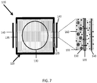
- FIG. 7 An example of an article 120 for the active transport of molecules using an electric field, as described herein, is shown in FIG. 7 .
- the article comprises an electric field generator 140, a chamber 125, at least one semipermeable material 135, and a sample positioner 130 as illustrated in FIG. 7 .
- the chamber is capable of being positioned in a field provided by the electric field generator (e.g., two electrodes; an anode and a cathode) and at least a wall of the chamber is defined by a semipermeable material (e.g., porous material, nanoporous material) having a specific molecular weight cutoff (e.g., between about 50,000 and about 500,000 g/mol; between about 100,000 g/mol and about 500,000; between about 500 g/mol and about 10,000 g/mol).
- a semipermeable material e.g., porous material, nanoporous material having a specific molecular weight cutoff (e.g., between about 50,000 and about 500,000 g/mol; between about 100,000 g/mol and about 500,000; between about 500 g/mol and about 10,000 g/mol).
- any suitable electric field generator capable of producing an electric field may be used.
- the electric field generator may comprise two or more electrodes (e.g., an anode and a cathode), driven by a source of electromotive force from a power supply.
- the electric field generator is capable of producing an electrostatic field.
- an electrostatic field may be produced by applying a static potential difference between at least two electrodes that do not move relative to the matrix during the process. Electrodynamic fields can be produced in a number of ways. In the context of the claimed invention, the orientation of apparatus that produces the field is changed relative to the matrix.
- a set of electrodes used to generate the field can be moved relative to the matrix by rotation or other movement about the matrix or the like, the matrix being moved.
- electrodes might not move relative to the matrix, but polarity and or extent of charge applied to the electrodes can be varied.
- a matrix might be surrounded by a number of electrodes each oriented differently relative to the matrix, and not changing in position relative to the matrix.
- Electromotive force applied to the electrodes can be changed in intensity over time to create a field that varies overtime, and polarity can change between electrodes such that the field moves in any of a variety of ways relative to the matrix.
- an electrodynamic field may be produced by dynamically changing the resistance of the matrix or the fluid surrounding the matrix. For instance, a highly viscous liquid can be injected or air bubbles can be introduced between the electrodes to increase the resistance of the surrounding fluid, which effectively enhances current going through the matrix.
- the chamber may be any suitable vessel capable of being positioned between the electric field generator, having at least a portion defined by a semipermeable material, housing a sample positioner, and retaining a fluid.
- the chamber is capable of being positioned in a field provided by the electric field generator.
- the chamber 125 is positioned between the electric field generator 140.
- the chamber may be capable of being positioned between two of the electrodes (e.g., an anode and a cathode).
- the chamber may be mobile and can be moved into the field manually or via automatic control.
- the chamber may be stationary and positioned such that the chamber is in the region in which the electric field generator provides electric fields.
- At least one wall of the chamber is defined by a semipermeable material.
- the semipermeable material may be a selectively permeable membrane.
- the semi-permeable material may allow certain molecules to be retained in the chamber while allowing other molecules to exit the chamber.
- retention of a desired molecule in the chamber may minimize the amount of molecule needed to achieve the desired outcome for a given application. For instance, retention of molecules used for staining the matrix may minimize the amount of staining molecules required to stain the matrix.
- retention of certain molecules may allow the molecules to evenly distribute within the chamber and/or prevent the molecules from interacting with the electric field generator.
- semipermeable material 135 may have a certain molecular weight cutoff and/or size cutoff, such that the semipermeable material is substantially impermeable to molecules at or above the molecular weight and/or size cutoff.
- a semipermeable material 135 may be substantially impermeable to molecules 150, but permeable to other molecules (e.g., 155 and 160) that have a smaller molecular weight and/or size.
- the semipermeable material may be porous.
- the semipermeable material may be a nanoporous material.
- the term "molecular weight cutoff" has its ordinary meaning in the art and may refer to the lowest molecular weight of a molecule at which greater than 90% of the molecule is retained by the semipermeable material or greater than 99% of the molecule is retained by the semipermeable material.
- One of ordinary skill in the art would be aware that the ability of a semipermeable material to retain a molecule is also dependent on the shape of the molecule, such that in some cases a molecule having the requisite molecular weight may not be retained due to its shape. For instance a linear molecule having the requisite molecular weight may not be retained while a globular molecule having the same molecular weight is retained.
- size cutoff has its ordinary meaning in the art and may refer to lowest size of a molecule at which greater than 90% of the molecule is retained by the semipermeable material or greater than 99% of the molecule is retained by the semipermeable material.
- the size of the molecule may be defined by the molecular weight of the molecule or a cross-sectional dimension of a molecule (e.g., globular molecule).
- the molecular weight and/or size cutoff may be selected based on one or more property of the molecule(s) to be retained.
- a semipermeable material with a relatively high molecular weight and/or size cutoff e.g., between about 50,000 g/mol and about 500,000 g/mol; between about 100,000 g/mol and about 500,000 g/mol
- a semipermeable material with a relatively high molecular weight and/or size cutoff may be used to retain molecules having a high molecular weight, such as antibodies.
- a semipermeable material with a relatively low molecular weight and/or size cutoff may be used to retain molecules having a low molecular weight, such as peptides, small molecules, oligomers, primers, etc.
- the semipermeable material may have a molecular weight cutoff of about 500,000 g/mol, about 350,000 g/mol, about 200,000 g/mol, about 100,000 g/mol, about 75,000 g/mol, about 50,000 g/mol, about 25,000 g/mol, about 10,000 g/mol, about 5,000 g/mol, about 3,000 g/mol, about 2,000 g/mol, about 1,000 g/mol, or about 500 g/mol.
- the molecular weight cutoff may be between about 500 g/mol and about 500,000 g/mol, about 1,000 g/mol and about 500,000 g/mol, about 10,000 g/mol and about 500,000 g/mol, about 50,000 g/mol and about 500,000 g/mol, about 100,000 g/mol and about 500,000 g/mol, about 500 g/mol and about 50,000 g/mol, about 500 g/mol and about 10,000 g/mol, about 500 g/mol and about 5,000 g/mol, about 1,000 g/mol and about 50,000 g/mol, or about 1,000 g/mol and about 10,000 g/mol.
- the semipermeable material may have a size cutoff of about 10 microns, about 5 microns, about 3 microns, about 2 microns, about 1 micron, about 0.8 microns, about 0.6 microns, about 0.5 microns, about 0.3 microns, about 0.2 microns, about 0.1 microns, about 0.05 microns, about 0.01 microns, about 0.005 microns, about 0.001 microns, or about 0.0005 microns.
- the size cutoff may be between about 0.001 microns and about 10 microns, about 0.001 microns and about 5 microns, about 0.001 microns and about 1 micron, about 0.001 microns and about 0.5 microns, about 0.001 microns and about 0.1 microns, about 0.1 microns and about 10 microns, about 0.1 microns and about 10 microns, or about 1 micron and about 10 microns.
- the average pore size of the semipermeable material may be less than or equal to about 5 microns, less than or equal to about 3 microns, less than or equal to about 2 microns, less than or equal to about 1 micron, less than or equal to about 0.8 microns, less than or equal to about 0.6 microns, less than or equal to about 0.5 microns, less than or equal to about 0.3 microns, less than or equal to about 0.2 microns, less than or equal to about 0.1 microns, less than or equal to about 0.05 microns, less than or equal to about 0.02 microns, less than or equal to about 0.01 microns, or less than or equal to about 0.005 microns and greater than zero.
- the article for active transport of molecules using an electric field does also comprise a sample positioner.
- the sample positioner is configured to hold a matrix (e.g., biological system).
- the sample positioner is also configured to move within the chamber.
- the matrix may be sufficiently secured to the sample positioner such that the matrix moves with the sample positioner.
- the sample positioner may be capable of oscillating and/or moving along a defined path.
- the movement of the sample positioner may be used to form an electrodynamic field.
- a matrix e.g., biological system
- the sample positioner may be rotated, such that the matrix experiences an electrodynamic field.
- the sample positioner may be configured to produce any suitable movement for the formation of static or dynamic electric fields.
- the sample positioner may move continuously or periodically.
- the positioner may be connected to a control system that controls the movement of the sample positioner.
- an article may optionally comprise one or more of an outer chamber, a temperature controller, a mixer, a buffer circulators, fluid inlet, or fluid outlet.
- the article may comprise an outer chamber that surrounds at least a portion of the chamber 125.
- the outer chamber may contain a fluid.
- the outer chamber is connected to a fluid recirculation system configured to transport fluid into and out of the chamber via one or more fluid inlet and outlet.
- the outer chamber and the chamber may be in fluid communication with one another via the semipermeable material.
- the article comprises one or more buffer circulator in fluid communication with the outer chamber and/or chamber.
- the buffer circulator may be used to replace, replenish, or move buffer within at least a portion of a chamber (e.g., outer chamber).
- the article may comprise a temperature controller.
- the temperature controller may be used to control the temperature of the fluid in at least a portion of the article.
- the temperature controller may be used to control the temperature of at least a portion of the fluid in the outer chamber and/or the chamber.
- the article may comprise a mixer that allows for the mixing of one or more fluid prior to entering a chamber and/or the mixing of one or more fluid in one or more chamber.
- a molecule may be or comprise a macromolecule (e.g., polymer), a biological macromolecule, a ligand, polynucleotide, oligonucleotide, protein, antibody, small molecule (e.g., organic, inorganic), nucleic acid, polysaccharides, or biologic.
- a macromolecule e.g., polymer
- a biological macromolecule e.g., a biological macromolecule
- a ligand e.g., polynucleotide
- oligonucleotide e.g., protein
- protein e.g., antibody
- small molecule e.g., organic, inorganic
- nucleic acid e.g., polysaccharides, or biologic.
- more than one type of molecule may be moved into, within, or from a matrix.
- the molecules may be of the same type or different type and may be selected from the above-referenced group.
- the molecule may be a photo luminescent molecule or comprise a photoluminescent molecule, such as a dye, a fluorescent molecule, or another photoluminescent molecule.
- the dye may be used for in vitro imaging.
- the molecule may be or comprise a pharmaceutically active agent (i.e., a drug).
- a pharmaceutically active agent may be any bio active agent.
- the pharmaceutically active agent may be selected from "Approved Drug Products with Therapeutic Equivalence and Evaluations," published by the United States Food and Drug Administration (F.D.A.) (the "Orange Book").
- the pharmaceutically active agent may be driven into a matrix and the matrix comprising the pharmaceutically active agent may be used for therapeutic applications.
- a matrix is or comprises one or more biological tissue (e.g., nervous tissue).
- suitable tissues include connective tissue, nervous tissue, muscle tissue (e.g., skeletal muscle tissue, cardiac muscle tissue, smooth muscle tissue), and epithelial tissue.
- the biological matrix may be a whole organ (e.g., brain) or a portion of an organ.
- organs that can be used, in part or whole, as a biological matrix include brain, heart, lung, intestine, stomach, spleen, skin, liver, prostate, bladder, pancreas, thyroid, kidney, bone, spinal cord, and eye, amongst others.
- the matrix may be a polymer matrix. Any suitable polymer matrix may be used. In some instances, the polymer matrix may be charged polymer matrix. In certain embodiments, the matrix may be a gel (e.g., hydrogel).
- a matrix may be a biological matrix.
- the cell may be a bacterium or other single-cell organism, a plant cell, fungal cell, or an animal cell.
- the cell may be a single-cell organism.
- single-cell organisms include a protozoan, a trypanosome, an amoeba, a yeast cell, and algae.
- the cell may be an animal cell.
- Non-limiting examples of the animal cells include, an invertebrate cell (e.g., a cell from a fruit fly), a fish cell (e.g., a zebrafish cell), an amphibian cell (e.g., a frog cell), a reptile cell, a bird cell, and a mammalian cell (e.g., human cell, primate cell, a bovine cell, a horse cell, a porcine cell, a goat cell, a dog cell, a cat cell, a cell from a rodent such as a rat or a mouse).
- the cell can be a human cell.
- the cell may be from a multi-cellular organism.
- the cell may be a neural cell, a cardiac cell, a fibroblast, a keratinocyte, a hepatocyte, a chondrocyte, a osteocyte, a muscle cell, a blood cell, an endothelial cell, an immune cell (e.g., a T-cell, a B-cell, a macrophage, a neutrophil, a basophil, a mast cell, an eosinophil), or a stem cell.
- an immune cell e.g., a T-cell, a B-cell, a macrophage, a neutrophil, a basophil, a mast cell, an eosinophil
- a molecule and a binding partner may associate via a chemical and/or biological interaction.
- a molecule and a binding partner may associate via a chemical interaction, such as a chemical bond.
- the chemical bond may be a covalent bond or non-covalent bond.
- the chemical bond is a non-covalent bond such as a hydrogen bond, ionic bond, dative bond, and/or a Van der Waals interaction.
- the molecule and binding partner may comprise functional groups capable of forming such bonds.
- a molecule may include at least one hydrogen atom capable of interacting with a pair of electrons on a hydrogen-bond acceptor of a binding partner to form the hydrogen bond.
- a molecule and/or a binding partner may include an electron-rich or electron-poor moiety, such that it may form an electrostatic interaction with another of a binding partner and/or molecule, respectively.
- covalent and non-covalent bonds between components may be formed by any type of reactions, as known to those of ordinary skill in the art, using the appropriate functional groups to undergo such reactions. Chemical interactions suitable for use with various embodiments described herein can be selected readily by those of ordinary skill in the art, based upon the description herein.
- an association between a molecule and a binding partner may occur via a biological binding event (i.e., between complementary pairs of biological molecules).
- a molecule may include an entity such as biotin that specifically binds to a complementary entity, such as avidin or streptavidin, on the binding partner.
- Other examples of biological molecules that may form biological bonds between pairs of biological molecules include, but are not limited to, proteins, nucleic acids, glycoproteins, carbohydrates, hormones, and the like.
- an antibody/peptide pair an antibody/antigen pair, an antibody fragment/antigen pair, an antibody/antigen fragment pair, an antibody fragment/antigen fragment pair, an antibody/hapten pair, an enzyme/substrate pair, an enzyme/inhibitor pair, an enzyme/cofactor pair, a protein/substrate pair, a nucleic acid/nucleic acid pair, a protein/nucleic acid pair, a peptide/peptide pair, a protein/protein pair, a small molecule/protein pair, a glutathione/GST pair, an anti-GFP/GFP fusion protein pair, a Myc/Max pair, a maltose/maltose binding protein pair, a carbohydrate/protein pair, a carbohydrate derivative/protein pair, a metal binding tag/metal/chelate, a peptide tag/metal ion-metal chelate pair, a peptide/NTA pair, a lectin
- Biological interactions between a molecule and a binding partner suitable for use in the embodiments described herein can be selected readily, by those of ordinary skill in the art, based upon the description herein as their function, examples of such biological interactions, and knowledge herein and in the art as to simple techniques for identifying suitable chemical interactions.
- condition that inhibits, facilitates, or enhances the association between a molecule and a binding partner may be one of pH, ionic concentration, concentration of a chemical species (e.g., formaldehyde, surfactant), or temperature.
- a chemical species e.g., formaldehyde, surfactant
- a molecule and/or matrix may be charged.
- the molecule to be moved by the electric field is charged or a precursor to a charged molecule.
- the methods and articles, described herein may be particularly well suited for the movement of charged molecules in the presence of a charged matrix.
- the term "charged molecule” and “charged matrix” have their ordinary meaning in the art and may refer to a molecule or matrix comprising one or more charged moiety.
- a "charged moiety” is a chemical moiety that carries a formal electronic charge, e.g., monovalent (+ 1), divalent (+ 2), trivalent (+ 3), etc.
- the charged moiety may be anionic (i.e., negatively charged) or cationic (i.e., positively charged).
- negatively- charged groups or precursors thereof include carboxylate groups, sulfonate group, sulfate groups, phosphonate groups, phosphate groups, hydroxyl groups, and the like.
- positively-charged moieties include amine groups (e.g., primary, secondary, and/or tertiary amines), ammonium groups, pyridinium group, and imidizolium groups.
- the charged moieties comprise sulfonate groups.
- the charged moiety may comprise -OH, -NH 3 +, -COO-, -SH, -CHO, a ketone, an azide, and/or a halide.
- the charge of the charged moiety may vary, in some cases, with the environmental conditions, for example, changes in pH may alter the charge of the moiety, and/or cause the moiety to become charged or uncharged.
- the charge of a moiety is determined under environmental conditions at which the molecule and/or matrix is used. In general, the charge density of the molecule and/or matrix may be selected as desired.
- the molecule and/or matrix may include one or more precursor moieties that can be converted to charged moieties.
- the molecule and/or matrix may include a neutral moiety that can be hydrolyzed to form a charged moiety, such as those described above.
- the matrix may include t -butyl acrylate and/or t -butyl methacrylate, which can be hydrolyzed to form an acrylic acid or a methacrylic acid, respectively.
- charge does not refer to a “partial negative charge” or “partial positive charge” on a molecule or matrix.
- the terms “partial negative charge” and “partial positive charge” are given its ordinary meaning in the art.
- a “partial negative charge” may result when a functional group comprises a bond that becomes polarized such that electron density is pulled toward one atom of the bond, creating a partial negative charge on the atom.
- an electric field may be used to move molecules into, within, or from at least a portion of a matrix.
- the magnitude of the electric field may be selected as desired for a given application.
- magnitude of the electric field may be greater than or equal to about 1 V/m, greater than or equal to about 2 V/m, greater than or equal to about 3 V/m, greater than or equal to about 5 V/m, greater than or equal to about 10 V/m, greater than or equal to about 20 V/m, greater than or equal to about 40 V/m, greater than or equal to about 50 V/m, greater than or equal to about 75 V/m, greater than or equal to about 100 V/m, greater than or equal to about 200 V/m, greater than or equal to about 500 V/m, greater than or equal to about 1,000 V/m, greater than or equal to about 2,500 V/m, greater than or equal to about 5,000 V/m, greater than or equal to about 10,000 V/m, greater than or equal to about 25,000 V/m,
- the magnitude of the electric field may be less than or equal to about 100,000 V/m, less than or equal to about 75,000 V/m, less than or equal to about 50,000 V/m, less than or equal to about 25,000 V/m, less than or equal to about 10,000 V/m, less than or equal to about 5,000 V/m, less than or equal to about 2,500 V/m, less than or equal to about 1,000 V/m, less than or equal to about 500 V/m, less than or equal to about 200 V/m, less than or equal to about 100 V/m, less than or equal to about 50 V/m, or less than or equal to about 10 V/m.
- the magnitude of an electrodynamic field may refer to the average magnitude of the field or any magnitude used in the dynamic field. In some embodiments, a higher electric field magnitude may be achieved without adversely affecting the matrix using an electric dynamic field.
- a dynamic electric field may be used to move molecules with respect to a matrix.
- at least one or more property of the electric field may changes as a function of time.
- the frequency of the changes in one or more property of the electric field may be greater than or equal to about 0.0001 Hz, greater than or equal to about 0.001 Hz, greater than or equal to about 0.01 Hz, greater than or equal to about 0.1, Hz greater than or equal to about 1 Hz, greater than or equal to about 5 Hz, greater than or equal to about 10 Hz, greater than or equal to about 20 Hz, greater than or equal to about 50 Hz, greater than or equal to about 100 Hz, greater than or equal to about 250 Hz, greater than or equal to about 500 Hz, greater than or equal to about 750 Hz, greater than or equal to about 1,000 Hz, greater than or equal to about 5,000 Hz, greater than or equal to about 10,000 Hz, greater than or equal to about 50,000 Hz, greater
- the frequency of the changes in one or more property of the electric field may be less than or equal to about 1,000,000 Hz, less than or equal to about 500,000 Hz, less than or equal to about 100,000 Hz, less than or equal to about 50,000 Hz, less than or equal to about 10,000 Hz, less than or equal to about 5,000 Hz, less than or equal to about 1,000 Hz, less than or equal to about 750 Hz, less than or equal to about 500 Hz, less than or equal to about 250 Hz, less than or equal to about 100 Hz , less than or equal to about 50 Hz, less than or equal to about 20 Hz, less than or equal to about 10 Hz, less than or equal to about 5 Hz, or less than or equal to about 1 Hz.
- Combination of the above-referenced ranges are also possible (e.g., greater than or equal to about 0.0001 Hz and less than or equal to about 10,000 Hz, greater than or equal to about 0.0001 Hz and less than or equal to about 100 Hz). Other values are also possible.
- two or more properties of the electric field may change as a function of time.
- two or more of the properties may change at the same or different frequencies.
- two or more of the properties may change at the same frequency.
- the magnitude and direction of the electric field may change at the same or different frequencies.
- one or more property may have a first frequency over a first time frame and a second frequency over a second timeframe.
- the direction of the electric field may have a frequency of 0.01 Hz for 5 minutes and a frequency of 10 Hz for 3 minutes.
- a property that has a certain frequency may change at regular, irregular, and/or stochastic intervals.
- an electric field may have a frequency of 1 Hz but the direction of an electric field may change such that the electric field has a first direction for 0.75 seconds and a second direction for 0.25 seconds.
- an electric field may also have a frequency of 1 Hz but the direction of an electric field may change such that the electric field has a first direction for 0.5 seconds and a second direction for 0.5 seconds.
- an electric field may be generated using any method known to those of ordinary skill in the art.
- the electric field may be a one-dimensional, two-dimensional, or three-dimensional electric field.
- a multi-dimensional electrodynamic field may be dynamic in one or more dimensions.
- a chamber may have any suitable shape or dimension.
- the dimensions of the chambers may be selected as desired.
- a chamber can have any suitable cross-sectional dimension.
- chamber may have a maximum cross-sectional dimension of greater than or equal to about 0.01 cm, greater than or equal to about 0.05 cm, greater than or equal to about 0.1 cm, greater than or equal to about 1 cm, greater than or equal to about 2 cm, greater than or equal to about 5 cm, greater than or equal to about 10 cm, greater than or equal to about 20 cm, greater than or equal to about 30 cm, greater than or equal to about 40 cm, greater than or equal to about 50 cm, greater than or equal to about 60 cm, greater than or equal to about 70 cm, greater than or equal to about 80 cm, or greater than or equal to about 90 cm.
- a chamber may have a maximum cross-sectional dimension of less than or equal to about 100 cm, less than or equal to about 90 cm, less than or equal to about 80 cm, less than or equal to about 70 cm, less than or equal to about 60 cm, less than or equal to about 50 cm, less than or equal to about 40 cm, less than or equal to about 30 cm, less than or equal to about 20 cm, less than or equal to about 10 cm, or less than or equal to about 5 cm. Combinations of the above-referenced ranges are also possible (e.g., greater than or equal to about 1 cm and less than or equal to about 100 cm). Other values of maximum cross-sectional dimensions are also possible.
- At least one or at least two cross-sectional dimensions (e.g., a height and a width) of chamber may be greater than or equal to about 0.01 cm, greater than or equal to about 0.05 cm, greater than or equal to about 0.1 cm, greater than or equal to about 1 cm, greater than or equal to about 2 cm, greater than or equal to about 5 cm, greater than or equal to about 10 cm, greater than or equal to about 20 cm, greater than or equal to about 30 cm, greater than or equal to about 40 cm, greater than or equal to about 50 cm, greater than or equal to about 60 cm, greater than or equal to about 70 cm, greater than or equal to about 80 cm, or greater than or equal to about 90 cm.
- At least one or at least two cross-sectional dimensions of chamber may be less than or equal to about 100 cm, less than or equal to about 90 cm, less than or equal to about 80 cm, less than or equal to about 70 cm, less than or equal to about 60 cm, less than or equal to about 50 cm, less than or equal to about 40 cm, less than or equal to about 30 cm, less than or equal to about 20 cm, less than or equal to about 10 cm, or less than or equal to about 5 cm. Combinations of the above-referenced ranges are also possible (e.g., greater than or equal to about 1 cm and less than or equal to about 100 cm). Other values are also possible.
- a chamber may have a certain width-to-height ratio.
- the ratio of the width to height of chamber may be greater than or equal to about 1:1, greater than or equal to about 2:1, greater than or equal to about 5:1, greater than or equal to about 10:1, greater than or equal to about 15:1, or greater than or equal to about 20:1.
- the width-to-height ratio may be less than or equal to about 30:1, less than or equal to about 20:1, less than or equal to about 15:1, less than or equal to about 10:1, less than or equal to about 5:1, or less than or equal to about 2:1. Combinations of the above-referenced ranges are also possible (e.g., greater than or equal to about 1:1 and less than or equal to about 20:1). Other values are also possible.
- the chamber may be defined by a semipermeable material.
- the semipermeable material forms a portion of one or more wall of the chamber.
- the percentage of one or more wall of the chamber or the entire chamber that is defined by a semipermeable material may be greater than or equal to about 1%, greater than or equal to about 5%, greater than or equal to about 10%, greater than or equal to about 20%, greater than or equal to about 30%, greater than or equal to about 40%, greater than or equal to about 50%, greater than or equal to about 60%, greater than or equal to about 70%, greater than or equal to about 80%, greater than or equal to about 90%, greater than or equal to about 95%, or greater than or equal to about 97%.
- the percentage of one or more wall of the chamber or the entire chamber that is defined by a semipermeable material may be less than or equal to about 100%, less than or equal to about 95%, less than or equal to about 90%, less than or equal to about 80%, less than or equal to about 70%, less than or equal to about 60%, less than or equal to about 50%, less than or equal to about 40%, less than or equal to about 30%, less than or equal to about 20%, or less than or equal to about 10%. Combinations of the above-referenced ranges are also possible (e.g., greater than or equal to about 5% and less than or equal to about 90%, greater than or equal to about 5% and less than or equal to about 100%). Other values are also possible.
- the sample positioner may have any suitable shape or dimension.
- the sample positioner may occupy a significant portion of the chamber.
- the ratio of the cross-sectional area of the chamber to the cross-sectional area of the sample positioner may be less than or equal to about 30:1, less than or equal to about 20:1, less than or equal to about 15:1, less than or equal to about 10:1, less than or equal to about 5:1, or less than or equal to about 2:1.
- the ratio of the cross-sectional area of the chamber to the cross-sectional area of the sample positioner may be greater than or equal to about 1:1, greater than or equal to about 1.5:1, greater than or equal to about 2:1, greater than or equal to about 5:1, greater than or equal to about 10:1, greater than or equal to about 15:1, or greater than or equal to about 20:1. Combinations of the above-referenced ranges are also possible (e.g., greater than or equal to about 1:1 and less than or equal to about 20:1). Other values are also possible.
- sample positioner may be selected as desired. It should be understood that a sample positioner can have any suitable cross-sectional dimension. For instance, in some embodiments, sample positioner may have a maximum cross-sectional dimension of greater than or equal to about 0.01 cm, greater than or equal to about 0.05 cm, greater than or equal to about 0.1 cm, greater than or equal to about 1 cm, greater than or equal to about 2 cm, greater than or equal to about 5 cm, greater than or equal to about 10 cm, greater than or equal to about 20 cm, greater than or equal to about 30 cm, greater than or equal to about 40 cm, greater than or equal to about 50 cm, greater than or equal to about 60 cm, greater than or equal to about 70 cm, greater than or equal to about 80 cm, or greater than or equal to about 90 cm.
- a sample positioner may have a maximum cross-sectional dimension of less than or equal to about 100 cm, less than or equal to about 90 cm, less than or equal to about 80 cm, less than or equal to about 70 cm, less than or equal to about 60 cm, less than or equal to about 50 cm, less than or equal to about 40 cm, less than or equal to about 30 cm, less than or equal to about 20 cm, less than or equal to about 10 cm, or less than or equal to about 5 cm. Combinations of the above-referenced ranges are also possible (e.g., greater than or equal to about 1 cm and less than or equal to about 100 cm). Other values of maximum cross-sectional dimensions are also possible.
- At least one or at least two cross-sectional dimensions (e.g., a height and a width) of sample positioner may be greater than or equal to about 0.01 cm, greater than or equal to about 0.05 cm, greater than or equal to about 0.1 cm, greater than or equal to about 1 cm, greater than or equal to about 2 cm, greater than or equal to about 5 cm, greater than or equal to about 10 cm, greater than or equal to about 20 cm, greater than or equal to about 30 cm, greater than or equal to about 40 cm, greater than or equal to about 50 cm, greater than or equal to about 60 cm, greater than or equal to about 70 cm, greater than or equal to about 80 cm, or greater than or equal to about 90 cm.
- At least one or at least two cross-sectional dimensions of sample positioner may be less than or equal to about 100 cm, less than or equal to about 90 cm, less than or equal to about 80 cm, less than or equal to about 70 cm, less than or equal to about 60 cm, less than or equal to about 50 cm, less than or equal to about 40 cm, less than or equal to about 30 cm, less than or equal to about 20 cm, less than or equal to about 10 cm, or less than or equal to about 5 cm. Combinations of the above-referenced ranges are also possible (e.g., greater than or equal to about 1 cm and less than or equal to about 100 cm). Other values are also possible.
- a sample positioner may have a certain width-to-height ratio.
- the ratio of the width to height of chamber may be greater than or equal to about 1:1, greater than or equal to about 2:1, greater than or equal to about 5:1, greater than or equal to about 10:1, greater than or equal to about 15:1, or greater than or equal to about 20:1.
- the width-to-height ratio may be less than or equal to about 30:1, less than or equal to about 20:1, less than or equal to about 15:1, less than or equal to about 10:1, less than or equal to about 5:1, or less than or equal to about 2:1. Combinations of the above-referenced ranges are also possible (e.g., greater than or equal to about 1:1 and less than or equal to about 20:1). Other values are also possible.
- antibody refers to an immunoglobulin or parts thereof, whether natural or wholly or partially synthetically produced. All derivatives thereof which maintain specific binding ability are also included in the term.
- the term also covers any protein having a binding domain which is homologous or largely homologous to an immunoglobulin binding domain. These proteins may be derived from natural sources, or partly or wholly synthetically produced.
- An antibody may be monoclonal or polyclonal.
- the antibody may be a member of any immunoglobulin class, including any of the human classes: IgG, IgM, IgA, IgD, and IgE. Derivatives of the IgG class, however, are preferred in the present invention.
- a biological macromolecule is a polynucleotide (e.g., RNA, DNA, RNA/DNA hybrid), protein, peptide, lipid, natural product, or polysaccharide.
- the biological macromolecule may be naturally occurring or non-naturally occurring.
- a biological macromolecule has a molecular weight greater than 500 g/mol.
- a ligand refers to any chemical compound, polynucleotide, peptide, protein, lipid, carbohydrate, small molecule, natural product, polymer, etc. that has a binding affinity for a target (e.g., a protein, carbohydrate, lipid, peptide, macromolecules, biological macromolecules, oligonucleotide, polynucleotide).
- a target e.g., a protein, carbohydrate, lipid, peptide, macromolecules, biological macromolecules, oligonucleotide, polynucleotide.
- the target is a protein.
- the ligand is specific for its target.
- the ligand has a binding affinity for the target in the range of 100 mM to 1 pM, preferably 1 mM to 1 pM, more preferably 1 ⁇ M to 1 pM.
- the ligand may bind to its target via any means including hydrophobic interactions, hydrogen bonding, electrostatic
- Polynucleotide or oligonucleotide refers to a polymer of nucleotides.
- the polymer may include natural nucleosides (i.e. , adenosine, thymidine, guanosine, cytidine, uridine, deoxyadenosine, deoxythymidine, deoxyguanosine, and deoxycytidine), nucleoside analogs (e.g., 2-aminoadenosine, 2-thiothymidine, inosine, pyrrolo-pyrimidine, 3-methyl adenosine, C5-bromouridine, C5-fluorouridine, C5-iodouridine, C5-propynyl-uridine, C5-propynyl-cytidine, C5-methylcytidine, 7-deazaadenosine, 7-deazaguanosine, 8-oxoadenosine, 8-
- methylated bases e.g. , methylated bases
- intercalated bases e.g. , modified sugars (e.g. , 2'-fluororibose, ribose, 2'-deoxyribose, arabinose, and hexose), or modified phosphate groups (e.g. , phosphorothioates and 5' -N-phosphoramidite linkages).
- modified sugars e.g. , 2'-fluororibose, ribose, 2'-deoxyribose, arabinose, and hexose
- modified phosphate groups e.g. , phosphorothioates and 5' -N-phosphoramidite linkages.
- a protein comprises a polymer of amino acid residues linked together by peptide (amide) bonds.
- a protein may refer to an individual protein or a collection of proteins.
- a protein may refer to a full-length protein or a fragment of a protein. Inventive proteins preferably contain only natural amino acids, although non-natural amino acids and/or amino acid analogs as are known in the art may alternatively be employed.
- amino acids in an inventive protein may be modified, for example, by the addition of a chemical entity such as a carbohydrate group, a hydroxyl group, a phosphate group, a farnesyl group, an isofarnesyl group, a myristoyl group, a fatty acid group, a linker for conjugation, functionalization, or other modification, etc.
- a protein may also be a single molecule or may be a multi-molecular complex comprising proteins, lipids, RNA, DNA, carbohydrates, etc..
- a protein may be a natural or unnatural fragment of a naturally occurring protein or peptide.
- a protein may be naturally occurring, recombinant, or synthetic, or any combination of these.
- small molecule refers to an organic or inorganic compound either synthesized in the laboratory or found in nature which has a molecular weight of less than about 2000 g/mole, or less than about 1000 g/mole, and even less than about 500 g/mole.
- Small molecules can refer to compounds that are "natural product-like", such as small molecule that are similar in structure to a natural product or are similar with respect to density of stereocenters, density of functional groups, ring systems, 3-D structure, etc. ; however, the term “small molecule” is not limited to "natural product-like" compounds and may include compounds that are not based on and are not similar to known natural products.
- Small molecules may include, for example, nucleic acids, peptides, polypeptides, peptide nucleic acids, peptidomimetics, carbohydrates, lipids or other organic (carbon containing) or inorganic moieties.
- This example describes the use of an electric field to transport molecules into a matrix.
- Optical clearing methods that increase the depth of light microscopy have been developed to image thick tissues without sectioning, but these methods do not enhance macromolecule penetration and therefore are not compatible with molecular phenotyping throughout the entire volume.
- a technique that renders thick tissue optically transparent and macromolecule-permeable has been developed. This technique enables complete access to whole mouse brain and thick postmortem human brain tissue via both light microscopy and molecular phenotyping techniques such as immunohistochemistry and in situ hybridization.
- molecular interrogation e.g., staining
- probe molecules e.g. antibodies
- an electric field was used to move charged molecules through the dense tissue many orders of magnitude faster than diffusion, with velocity proportional to the quadratic of the strength of the electric field. Therefore, electrophoretic movement was used to rapidly and actively transport charged molecules with desired functionality-such as detergent molecules for lipid removal or antibody molecules for immunolabeling-through the thick tissue, allowing for fast optical clearing and molecular phenotyping. Furthermore, by strategically optimizing macrofluidic circuit arrangement and adjusting the composition, temperature, and viscosity of the solution, one can concentrate the current flow to the tissue and expedite the process.
- acrylamide monomers, formaldehyde and polymerization initiators were infused into the brain at 4°C to crosslink the tissue and to link acrylamide molecules to the tissue.
- Thermally triggering polymerization reaction at 37°C formed a tissue-acrylamide polymer hybrid construct.
- the tissue-polymer hybrid was subject to electrophoresis in ionic detergent solution for the removal of lipids and other un-crosslinked molecules.
- electrophoresis device that involved a large amount of outer channel circulation and a small amount of inner circulation ( FIG. 8B -E ).
- FIG. 8 An important feature of this device was the spatial isolation of central tissue-containing reaction chamber (a part of inner circulation) from surrounding electrolysis chamber (a part of outer circulation) by nanoporous semi-permeable membranes ( FIG. 8 ). This allowed independent and versatile control of solution composition, temperature, conductivity and reaction volume in reaction and electrolysis chambers to be achieved.
- the tissue-polymer hybrid was placed on the holder that was attached to a step motor for rotation. Rotation allowed the uniform distribution of charged molecules throughout the specimen and to prevent tissue deformation during the clearing procedure. Another key feature was macrofluidic arrangements. Incoming solution effectively washed out the products of electrolysis, preventing concentration of acids or bases at each electrode. The charge of the protein was controlled by changing the pH. At high pH, most proteins had net negative charges.
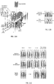
- FIG. 8 illustrates the principles and implementation of electrophoretic random walk.
- FIGS. 8A-8C show the comparison of Brownian random walk (top) with electrophoretic linear transport (middle) and electrophoretic random walk (bottom).
- Computer simulation results (A), schematic diagram (B) and immunostaining results (C) are shown.
- Circles 1 and 2 represent charged particles of the same mass, and black dot represent a particle with smaller mass. Particle 2 bears higher charge than particle 1.
- Brownian random walk particles make small random movements, resulting in a small net displacement. Therefore, tissue penetration of the particles is slow and molecules accumulate in the surface. In the electric field, particles with higher charge moves faster than particles with smaller charge. Charged molecules can rapidly penetrate through the tissue, but their distribution follows electric field gradient.
- Electrophoresis chamber consists of an inner chamber and two outer chambers. Inner chamber has a lid with a step motor and its controller.
- FIG. 8E is a bird's eye view of the device.
- FIG. 8F is a top view of the device.
- the tissue sample was isolated from the electrochemical reactions in both electrodes. As nanoporous membranes were not permeable to large molecules, such molecules with desired properties were confined to the small volume of the inner chamber and were uniformly distributed.
- FIG. 9 illustrates the electrophoretic random walk with dynamic affinity shift that allowed for the rapid and uniform immunolabeling of large intact tissues.
- FIG. 9A is a schematic of the immunolabeling device. For this experiment, 13ml of lithium borate buffer (50mM, pH 11) containing antibodies was loaded in the inner chamber and a large volume of cooled lithium borate buffer (50mM; pH 9; 4°C) was circulated through the outer chambers. 50V was applied across the inner chamber. The small buffer molecules could freely pass through the nanoporous membrane, but antibodies were secured within the inner chamber. This unique design protected the important biomolecules from degradation by electro-oxidation/reduction.
- FIG. 9B illustrates the time-course of pH change in the inner chamber during the electrophoresis.
- FIG. 9C is a representative images of 1-mm thick Thyl-eGFP brain sections stained against eGFP at buffers with different pH. Higher antibody-antigen binding occurred at pH 9.
- FIG. 9D is a schematic of antibody penetration and distribution throughout the tissue over time. Antibody molecules are highly charged at high pH; therefore, tissue penetration and uniform distribution of antibodies under the electrophoretic random walk regime was the most efficient at high pH. As pH decreased, distributed antibodies start to bind their target antigens.
- FIG. 9C is a representative images of 1-mm thick Thyl-eGFP brain sections stained against eGFP at buffers with different pH. Higher antibody-antigen binding occurred at pH 9.
- FIG. 9D is a schematic of antibody penetration and distribution throughout the tissue over time. Antibody molecules are highly charged at high pH; therefore, tissue penetration and uniform distribution of antibodies under the electrophoretic random walk regime was the most efficient at high pH. As pH decreased, distributed antibodies start to bind their target antigens.
- 9E are representative images of whole Thyl-eGFP mouse brains stained against eGFP (left) only with electrophoresis, (middle) with electrophoresis and rotation and (right) with electrophoresis, rotation and dynamic affinity shift.
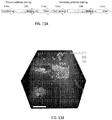
- FIG. 10 illustrates the rapid clearing and immunostaining of thick human brain samples.
- FIG. 10A is a schematic of the clearing setup. Charged SDS micelles were confined in the inner chamber by nanoporous membranes and were actively transported through the rotating tissue, mimicking random walk. SDS micelles were not able to cross the nanoporous membranes, whereas SDS monomers were.
- FIG. 10B is a graph of the pH change over time for the present technique (new clarity) and a previous technique (old clarity) that shows that the present technique does not cause drop in pH.
- FIG. 10C are representative images of cleared brains at different time points. The present technique more rapidly clears the brain than old CLARITY.
- FIG. 10D shows the uniform and complete immunostaining of thick human brain tissue was possible with the present technique.
- FIG. 10E -G show high-magnification images of brain tissue.
- FIG. 10H shows a graph of the dendritic bridges/neurons for a given large of the brain as determined using the present
- This example describes a transport method, referred to in this example as stochastic electrotransport, which allows rapid and selective transport of charged molecules without disrupting the surrounding charged matrix.
- a device was designed to implement stochastic electrotransport of detergent micelles to enable rapid and uniform clearing of intact tissues. With this device, a whole adult mouse brain tissue was cleared in as short as 3 days.
- a modified device was designed to implement stochastic electrotransport of molecular probes to allow for the rapid and uniform staining of intact tissues.
- the versatility of this approach was demonstrated by staining a cleared hydrogel whole adult mouse brain with synthetic nuclear stains, carbohydrate-binding proteins, and antibodies. The technique resulted in strikingly uniform and rapid labeling of various biomolecules in organ-scale mammalian tissues. Taken together, stochastic electrotransport further facilitated rapid and multi-dimensional interrogation of large-scale intact biological systems.
- a sufficiently strong electric field can expedite the transport of ions with their velocity linearly dependent on their electromobility, while non-charged materials (e.g. polyacrylamide and agarose gels) remain stationary. Stationary electric gradient, however, can irreversibly deform the surrounding matrix if the matrix itself is charged.
- Charged ionic matrices are commonly found and include all biological tissues, but one specific example is a cleared hydrogel-tissue hybrid. In certain hydrogel-tissue hybrids, the small building blocks of the hydrogel mesh are infused into a tissue and subsequently polymerized to form an interconnected nanoporous mesh. During this process, endogenous biomolecules (e.g.
- nucleic acids, proteins, and small molecules are preserved at their physiological location by crosslinking to the synthetic polymer chains and certain molecules (e.g., lipids) are removed from the tissue to produce an optical transparent (“cleared") hydrogel-tissue hybrid.
- certain molecules e.g., lipids
- stochastic electrotransport which selectively expedites the transport of freely moving charged molecules without damaging the surrounding charged matrix.
- Stochastic electrotransport hinges on the idea that a stochastic electric field can selectively enhance the transport of particles with large electromobilities by inducing an electrically-driven 'random walk'.
- Our computational simulation using a Kinetic Monte Carlo model predicted that in the presence of a locally stochastic electric field caused by a dynamically changing electric field and a chaotic distribution of pores, the mean squared displacement, ⁇ R 2 ⁇ , of particles scales quadratically with the product of their electromobilities and the field strength (normalized by effective rotation time scale P and experiment time t).
- this new transport strategy was applied to transporting detergent sodium dodecyl sulfate (SDS) micelles for expediting extraction of lipids from hydrogel-embedded intact tissues.
- SDS detergent sodium dodecyl sulfate
- FIG. 11A The device is shown in FIG. 11A .
- a sample was continuously rotated with respect to an electrostatic field to create an electric force that dynamically changed with time in both direction and magnitude.
- This electrodynamic field combined with the chaotically distributed pores within the tissue sample, generated an electrophoretically driven random walk of charged molecules.
- nanoporous membranes was introduced to separate "inner” and “outer” channels that circulated clearing buffer (200 mM SDS, 10 mM lithium borate, pH 9) and electrophoresis buffer (10 mM SDS, 10 mM lithium borate, pH 9).
- the nanoporous membrane allowed only small chemicals including current-carrying ions and SDS monomers to move freely across the two channels, while confining large SDS micelles inside.
- the unique design not only kept the concentration of SDS high inside the inner channels, but also protected the sample from destructive chemical reactions and their by-products (e.g. various acids and bases.)
- the nanoporous membrane effectively blocked by-products of electrolysis from entering the inner circulation and thus protected the sample.
- the device was revised to implement stochastic electrotransport of molecular probes into the cleared tissues.
- Sample rotation was maintained, but the nanoporous membranes that separated inner and outer channels were removed.
- the sample chamber was walled with a nanoporous membrane to maintain the concentration of probes high inside the chamber and to protect the sample and probes from electrolysis and its by-products.
- a disk-shape acrylamide gel larger than a mouse brain (radius, 9 mm; height, 8 mm) was placed into the chamber loaded with fluorescein-conjugated bovine serum albumin (BSA-FITC) and a stochastic electric field was applied.
- BSA-FITC fluorescein-conjugated bovine serum albumin
- Simultaneous stochastic electrotransport of these probes into a mouse brain for a day achieved remarkably uniform and complete staining of their targets in the whole brain as shown in FIG. 12A .
- antibodies have the highest molecular weight ( ⁇ 150 kDa) and thus exhibited poorest penetration ( ⁇ 300 um) in the passive staining experiment, whereas penetration was complete throughout the entire depth of imaging in case of stochastic electrotransport.
- FIG. 11A shows a schematic of the device designed for implementing stochastic electrotransport for tissue-clearing.
- Inner circulation of the clearing solution 200 mM SDS, 10 mM LB, pH 9) and outer circulation of the electrophoresis buffer (10 mM SDS, 10 mM LB, pH 9) were separated by the nanoporous membrane (inset), which kept SDS micelles within the inner circulation and by-products of electrolytic reactions within the outer circulation.
- SDS monomers and buffer ions could freely move across the nanoporous membranes.
- SDS monomer concentration equilibrated at ⁇ 10 mM in both inner and other chambers.
- FIG. 11B shows coronal sections. Arrowhead points at deformed parts of the tissue. Passive diffusion of SDS at 37°C with shaking for the same duration only partially cleared the surface. All grids are 3 mm x 3 mm. See
- FIG. 12A shows a cleared hydrogel adult mouse brain that was subject to stochastic electrotransport of SYTO® 16 (a cyanic nuclear stain), Dylight® 594-conjugated tomato lectin (a carbohydrate-binding protein that labels blood vessels), and Alexa® 647-conjugated anti-histone H3 antibodies (labels all cell nuclei). Horizontal sections showed uniform and complete staining of the whole brain with all three probes used. The scale bar is 1 mm.
- FIG. 12B shows the passive staining controls that were incubation for the same duration in 37°C with gentle shaking. The scale bar is 1 mm.
- eTANGO electroactiveochastic Transport of Activity modulated molecules in Nanoporous Gel Organ hybrid
- the versatility of the integrated approach was demonstrate by achieving 3D visualization of cellular nuclei, vasculature, and various neuronal cell types in whole mouse using three different classes of molecular probes.
- the technique's specificity was also validated by staining against genetically expressed fluorescent proteins. The technique allowed strikingly uniform and rapid labeling of various biomolecules in organ-scale mammalian tissues.
- a novel integrated platform with several key features was developed.
- temperature-controlled buffer solution flowed around the cylindrical chamber to finely control the reaction environment (e.g. temperature and pH) within the tissue.
- the device was integrated the with off-device components to automate the stochastic electrotransport process.
- probe migration time scale hours
- reaction time scale sub-seconds to minutes
- binding activity of probes was dynamically modulated the during the labeling process by utilizing the fact that non-covalent binding reactions between molecules is governed by their weak interactions (e.g. electrostatic, hydrophobic, hydrogen bonding) and the strength of such forces is dependent on the surrounding chemical environment.
- this buffer system could be readily used with the stochastic electrotransport system, described herein, to dynamically modulate binding activity of the probes in the course of molecular labeling of intact tissues.
- the integration of this '"dynamic activity shift" with stochastic electrotransport is referred to in this example as eTANGO. Table 1.
- Probes used in this Example Probe Vendor Dilution Alexa ® 647-conjugated ⁇ -eGFP antibody Life technologies 1:100 Alexa ® 647-conjugated ⁇ -histone H3 antibody Cell Signaling (1) 1:250 (2) 1:100 ⁇ -Histone H3 antibody Abcam 1:100 ⁇ -Myelin basic protein antibody Abcam 1:250 ⁇ -NeuN antibody Abcam 1:250 ⁇ -Neurofilament antibody [SMI-312] Covance 1:250 ⁇ -Parvalbumin antibody Abcam (1) 1:250 (2) 1:100 ⁇ -Tyrosine hydroxylase antibody Abcam 1:150 Secondary antibodies All from Abcam (1) 1:250 (2) 1:150 PO-PRO-1 Life Technologies (1) 1:250 (2) 1:100 DAPI Life Technologies 1:50,000 Neurotrace 500/525 Life Technologies 1:250 Dylight ® 594-conjugated tomato lectin Vector Labs (1) 1:250 (2) 1:50
- PO-PRO-1 a widely used organic nuclear dye
- PO-PRO-1 exhibited strong labeling in pH 7.5 tris-borate (TB) buffer while it has nearly no signal in pH 11 LB with SDS.
- PO-PRO-1 has two positive charges regardless of pH, making it suitable for both stochastic electrotransport and dynamic activity shift.
- the tissue was loaded into the sample chamber with PO-PRO-1 and a non-binding buffer (pH 11 LB buffer containing SDS), which facilitated probe transport without allowing probe-target binding reaction to occur.
- a non-binding buffer pH 11 LB buffer containing SDS
- the same buffer with no probes was circulated through the device and a stochastic electric field was applied to drive the inactivated probes into the tissue.
- the sample was moved to a 'binding buffer' that fostered probe-target binding reaction (pH 7.5 TB buffer) and passively incubated overnight. This approach resulted in remarkably uniform and complete nuclear staining of the whole hemisphere within only 15 hours.
- eTANGO a carbohydrate-binding protein widely used as an effective blood vessel marker
- Lectin a carbohydrate-binding protein widely used as an effective blood vessel marker
- a fluorophore-conjugated Lycopersicon Esculentum (tomato) lectin showed strong binding to its targets at neutral pH but with high background in the buffers tested, whereas labeling was weaker but more specific at both neutral and basic pH in the presence of 10mM SDS.
- pH 11 LB buffer with SD was used as a slow binding buffer because lectin-whose isoelectric point (pI) is 9.0-is more highly charged at basic pH, allowing faster electrophoretic transport.
- the strong binding step was omitted.
- uniform and complete staining of the entire vasculature of a whole mouse hemisphere was achieved within 10 hours.
- the sample was then optically cleared using a custom-made, refractive-index-matching immersion medium.
- Light-sheet microscopy was used to rapidly acquire high-resolution volume images.
- the acquired images displayed uniform staining of capillaries as well as larger blood vessels at different depths.
- a separate z-stack of images with 2 um steps was obtained within 30 seconds.
- Acquired images could be easily vectorized due to their high contrast and analyzed for various parameters, such as diameter, total length, and number of branch points.
- Such quantitative analysis of brain-wide vasculature may reveal important structural or pathological features of the vascular network in normal or diseased tissues. This further extends the utility of eTANGO for rapid and quantitative phenotyping of organ-scale biological systems.
- eTANGO was compatible with immunohistochemical methods. Immunohistochemistry is one of the most commonly used molecular phenotyping techniques employing antibody-antigen binding reactions. However, due to the large size of antibodies (15 nm) and their slow mobility, antibody labeling of thick intact tissue has remained a major challenge. To investigate if eTANGO allows for rapid, complete, and uniform immunolabeling of large-scale intact tissues, eTANGO was performed to label all cellular nuclei throughout an entire mouse hemisphere using dye-conjugated ⁇ -histone H3 (H3) antibody. First, it was determined if uniform staining could be achieved using stochastic electrotransport alone.
- H3 dye-conjugated ⁇ -histone H3
- ⁇ -GFP was performed staining on an intact, cleared hydrogel Thyl-eGFP adult mouse brain.
- the eTANGO processed brain exhibited strikingly uniform and complete ⁇ -GFP labeling of all eGFP-expressing neurons throughout the whole brain.
- another brain was passively immunostained for the same duration and observed only surface-limited labeling.
- eTANGO-stained hippocampus, cortex, and thalamus containing varying amounts of eGFP(+) neurons revealed that eTANGO was capable of uniformly immunostaining samples with heterogeneously distributed antigens.
- the most widely used immunohistochemical method is indirect immunostaining-by first using target-specific primary antibody staining and then adding host-species-specific secondary antibodies that bind to the primary antibodies-as it allows signal amplification and obviates the need for conjugating fluorophores to all antigen-specific antibodies. Therefore, eTANGO was applied to indirectly immunostain various cellular markers using two consecutive non-binding and binding cycles as shown in FIG. 13A .
- eTANGO labeling of whole mouse brain with tyrosine hydroxylase (TH) which is an enzyme important for catecholamine biosynthesis that is commonly used for visualizing dopaminergic neurons in the midbrain areas, was performed in conjunction with H3 as a nuclear counterstain using a non-fluorophore-conjugated ⁇ -H3 antibody.
- ⁇ -H3 antibody labeled all nuclei whereas strong ⁇ -TH antibody signal was restricted to well-known midbrain dopamine centers, such as the ventral tegmental area (VTA) and the substantia nigra (SN) as shown in FIG. 13B .
- VTA ventral tegmental area
- SN substantia nigra
- a simple intensity thresholding algorithm precisely identified H3- and TH-immunoreactive cells and counted the total number of cells and TH-expressing neurons in the medial VTA, which was possible owing to uniform labeling over the large volume.
- PV parvalbumin
- FIGs. 13A -B show (13A) an eTANGO experimental protocol for indirect immunohistochemistry and (13B) a 3D rendering of ventral tegmental area (VTA) of a 3-month old Thyl-eGFP M line mouse brain after whole-brain immunostaining against TH and H3 with eTANGO (SN is substantia nigra and cp is cerebral peduncle) with a scale bar equal to 300 ⁇ m.
- VTA ventral tegmental area
- mice Male C57BL/6 mice, aged 6-8 weeks at the start of experiments, were housed in a reverse 12-hr light/dark cycle. Food and water were given ad libitum.
- tissue was sectioned using a mouse brain matrix (RBM-2000C; ASI Instruments, Warren, MI) after the hydrogel tissue embedding step. 100 ⁇ m-thick sections were obtained with a vibratome (VT1200S; Leica, Buffalo Grove, IL). The tissue blocks were passively cleared by incubating in 50 mL clearing solution at 37°C with gentle shaking until fully cleared. Cleared tissue blocks were then placed into a 24 well plate and washed with staining buffer solutions (indicated in each figure) three times, two hours each. Then the tissue blocks were incubated in the same staining buffer solution and washed three times before imaging. For indirect immunostaining, the previous step was repeated for secondary antibodies after primary antibodies. All washing and staining processes were done at room temperature with gentle shaking. Stained sections were then optically cleared and imaged or directly imaged.
- eTANGO solution preparation Prepare non-binding and binding buffers of choice.
- the following buffers were used (1) pH 11 LB buffer + SDS that contained 50 mM lithium hydroxide, 10 mM SDS, 1% Triton-X 100, and 0.02% sodium azide and was titrated with boric acid to pH 11; (2) pH 11 LB buffer that contained 50 mM lithium hydroxide, 1% Triton-X 100, and 0.02% sodium azide and was titrated with boric acid to pH 11; (3) pH 9 LB buffer that contained 50 mM lithium hydroxide, 1% Triton-X 100, and 0.02% sodium azide and was titrated titrated with boric acid to pH 9; (4) pH 7.5 TB buffer that contained 50 mM Trizma base (Sigma T6066), and 0.02% sodium azide and was titrated with boric acid to pH 7.5.
- eTANGO device eTANGO device, sample chamber, and associated accessories (chamber cap, motor, and motor controller) were custom-made and assembled.
- the device was constructed as follows. (1) A heat exchanger was made by immersing 2 meters of 1/4" rigid, thin-walled tubing (McMaster-Carr) in a refrigerated bath circulator (WiseCircu WCR-P8, 1.6 kW; Wisd Laboratory Instruments; Germany) set to 1 °C; (2) Nanoporous membranes was mounted to the sample chamber using an electricity-resistant epoxy glue (Hysol ES1901; Henkel). Pore size (molecular weight cutoff, i.e., MWCO) of the membrane was smaller than the molecular weight of the desired probe.
- the following membranes from Spectrum Laboratories were used MWCO of 1 kDa for antibodies, MWCO 6-8 kDa for antibodies and lectins; MWCO 100-500 Da for PO-PRO-1.
- the system was connected in the following order (in the direction of flow): pump (40PX, PanWorld, Japan), heat exchanger, eTANGO chamber, and reservoir. The heat exchanger was placed directly before eTANGO chamber for efficient cooling. All components were connected with appropriately sized tubing (1/8", 3/8").
- the eTANGO device was placed on top of a magnetic stirring plate (HI 190M, Hanna Instruments, RI) and a small stirring bar was added (30620-416; VWR).
- a nylon mesh (CMN-0074-D, Small Parts) was used to build a wall around the tissue holder to secure the tissue in place. The measured temperature of the outer solution was 10-13°C.
- the eTANGO process was performed using the following steps. (1) Wash cleared hydrogel tissue in non-binding buffer 2-3 times at room temperature for a day with gentle shaking to equilibrate the tissue with non-binding buffer. Alternatively, tissue can be electrophoretically washed with the eTANGO device to reduce time for washing. (2) Fill the reservoir with non-binding buffer, close the device, and start circulation. Wait until the solution cools down to 10-13°C. (3) Place the tissue inside the chamber and load the chamber with non-binding buffer with 3% bovine serum albumin (BSA). Just enough buffer solution (3-5 ml of buffer solution) was used to immerse the tissue in the solution. (4) Apply electric field for 10 min to disperse BSA in the chamber.
- BSA bovine serum albumin
- This non-binding/binding cycle can be repeated several times to enhance uniformity of staining.
- PROTOS pH/Refractive index/Osmolarity Tunable Optical-clearing Solution
- 75 g diatrizoic acid D92681 Sigma-Aldrich
- 70 g d-sorbitol S1876; Sigma-Aldrich
- 23g n-methyl-d-glucamine M2004; Sigma-Aldrich
- Tissue deformation experiment To assess the extent to which stochastic electrotransport deforms tissue samples, a cleared brain tissue was placed in eTANGO device and subjected to 50 V with rotation in pH 11 LB buffer. For ID electrophoresis only, another tissue was positioned in eTANGO device in such a way that lateral sides (but not dorsal and ventral surfaces) were close to the electrodes and was not rotated.
- eTANGO sample chamber was loaded with BSA-FITC solution (1 mg/ml in pH 7.5 TB) with rounded side of disk-shape gel touching the bottom of the chamber, and flat sides standing upright. pH 7.5 TB was circulated throughout the setup. 200 V was then applied for 1 hr or 3 hrs to transport BSA-FITC into the gel. 3 mm-thick cross-section from the middle was then obtained using a rat brain matrix and imaged with a fluorescence stereomicroscope.
- a reference to "A and/or B,” when used in conjunction with open-ended language such as “comprising” can refer, in one embodiment, to A without B (optionally including elements other than B); in another embodiment, to B without A (optionally including elements other than A); in yet another embodiment, to both A and B (optionally including other elements); etc.
- the phrase "at least one,” in reference to a list of one or more elements, should be understood to mean at least one element selected from any one or more of the elements in the list of elements, but not necessarily including at least one of each and every element specifically listed within the list of elements and not excluding any combinations of elements in the list of elements.
- This definition also allows that elements may optionally be present other than the elements specifically identified within the list of elements to which the phrase "at least one" refers, whether related or unrelated to those elements specifically identified.
- At least one of A and B can refer, in one embodiment, to at least one, optionally including more than one, A, with no B present (and optionally including elements other than B); in another embodiment, to at least one, optionally including more than one, B, with no A present (and optionally including elements other than A); in yet another embodiment, to at least one, optionally including more than one, A, and at least one, optionally including more than one, B (and optionally including other elements); etc.
Landscapes
- Health & Medical Sciences (AREA)
- Life Sciences & Earth Sciences (AREA)
- Chemical & Material Sciences (AREA)
- Molecular Biology (AREA)
- Analytical Chemistry (AREA)
- General Health & Medical Sciences (AREA)
- Chemical Kinetics & Catalysis (AREA)
- General Physics & Mathematics (AREA)
- Biochemistry (AREA)
- Physics & Mathematics (AREA)
- Immunology (AREA)
- Pathology (AREA)
- Electrochemistry (AREA)
- Engineering & Computer Science (AREA)
- Hematology (AREA)
- Clinical Laboratory Science (AREA)
- Power Engineering (AREA)
- Biomedical Technology (AREA)
- Apparatus Associated With Microorganisms And Enzymes (AREA)
- Pharmaceuticals Containing Other Organic And Inorganic Compounds (AREA)
- Medicines Containing Antibodies Or Antigens For Use As Internal Diagnostic Agents (AREA)
- Physical Or Chemical Processes And Apparatus (AREA)
Claims (14)
- Article (120) comprenant :un générateur de champ électrique (140) ;une chambre (125) apte à être positionnée dans un champ fourni par le générateur (140), dans lequel au moins une paroi de la chambre comprend un matériau semi-perméable (135) ; etun positionneur d'échantillon de tissu biologique (130) dans la chambre (125), caractérisé en ce que le positionneur d'échantillon de tissu biologique (130) est configuré pour déplacer un tissu biologique dans la chambre (125) d'une manière qui expose le tissu biologique à un champ électrodynamique lorsque le positionneur d'échantillon de tissu biologique (130) est positionné dans un champ électrique statique produit par le générateur (140) pour transporter des molécules (50) à travers au moins une portion du tissu biologique.
- Article (120) selon une quelconque revendication précédente, dans lequel :a) le positionneur d'échantillon (130) est apte à osciller et/ou se déplacer le long d'un trajet défini ; oub) le positionneur d'échantillon (130) est raccordé à un système de commande qui commande le mouvement du positionneur d'échantillon (130).
- Article (120) selon une quelconque revendication précédente, comprenant en outre une chambre extérieure apte à retenir un fluide qui entoure au moins une portion de la chambre (125).
- Article (120) selon la revendication 3, dans lequel la chambre extérieure et la chambre (125) sont en communication fluidique seulement via le matériau semi-perméable (135).
- Article (120) selon une quelconque revendication précédente, dans lequel :a) le générateur de champ électrique (140) comprend deux ou plus électrodes ;b) le générateur de champ électrique (140) comprend une anode et une cathode ; ouc) la chambre (125) est positionnée entre deux électrodes.
- Article (120) selon une quelconque revendication précédente, dans lequel le générateur de champ électrique (140) comprend une anode et une cathode, et dans lequel la chambre (125) est positionnée entre l'anode et la cathode.
- Article (120) selon une quelconque revendication précédente, dans lequel la chambre (125) est apte à retenir un fluide.
- Article (120) selon une quelconque revendication précédente, dans lequel le rapport entre une aire transversale de la chambre (125) et une aire transversale du positionneur d'échantillon (130) est supérieur à ou égal à 20:1.
- Article (120) selon une quelconque revendication précédente, dans lequel :a) le seuil de poids moléculaire du matériau semi-perméable est entre 50 000 g/moles et 500 000 g/moles ;b) le seuil de poids moléculaire du matériau semi-perméable est entre 500 g/moles et 10 000 g/moles.
- Article (120) selon l'une quelconque des revendications 1 à 8,
dans lequel le seuil de poids moléculaire du matériau semi-perméable est entre 100 000 g/moles et 500 000 g/moles. - Article (120) selon une quelconque revendication précédente, dans lequel le matériau semi-perméable est un matériau poreux.
- Article (120) selon une quelconque revendication précédente, dans lequel le matériau semi-perméable présente une taille de pore moyenne entre 0,001 micron et 10 microns.
- Article (120) selon une quelconque revendication précédente, dans lequel le matériau semi-perméable présente un seuil de taille entre 0,001 micron et 1 micron.
- Article (120) selon une quelconque revendication précédente, comprenant :a) un dispositif de commande de température ;b) un mélangeur ;c) un circulateur de fluide, en option dans lequel le fluide est un liquide, en option dans lequel le liquide comprend un tampon ; oud) une entrée de fluide et une sortie de fluide.
Applications Claiming Priority (2)
| Application Number | Priority Date | Filing Date | Title |
|---|---|---|---|
| US201461975575P | 2014-04-04 | 2014-04-04 | |
| PCT/US2015/024297 WO2015154000A1 (fr) | 2014-04-04 | 2015-04-03 | Transport actif de molécules chargées dans des matrices chargées, à l'intérieur de celles-ci et/ou à partir de celles-ci |
Publications (3)
| Publication Number | Publication Date |
|---|---|
| EP3126037A1 EP3126037A1 (fr) | 2017-02-08 |
| EP3126037A4 EP3126037A4 (fr) | 2018-01-24 |
| EP3126037B1 true EP3126037B1 (fr) | 2020-11-18 |
Family
ID=54209548
Family Applications (1)
| Application Number | Title | Priority Date | Filing Date |
|---|---|---|---|
| EP15773329.6A Active EP3126037B1 (fr) | 2014-04-04 | 2015-04-03 | Transport actif de molécules chargées dans des matrices chargées, à l'intérieur de celles-ci et/ou à partir de celles-ci |
Country Status (4)
| Country | Link |
|---|---|
| US (2) | US10416116B2 (fr) |
| EP (1) | EP3126037B1 (fr) |
| CN (1) | CN106211762B (fr) |
| WO (1) | WO2015154000A1 (fr) |
Families Citing this family (7)
| Publication number | Priority date | Publication date | Assignee | Title |
|---|---|---|---|---|
| CN106211762B (zh) | 2014-04-04 | 2020-08-14 | 麻省理工学院 | 向带电基质中、在带电基质中和/或从带电基质中主动转运带电分子 |
| TWI588158B (zh) * | 2015-04-22 | 2017-06-21 | Nat Applied Res Laboratories | Method of making protein wafer |
| WO2017190101A1 (fr) | 2016-04-29 | 2017-11-02 | Massachusetts Institute Of Technology | Procédés de grossissement réversible et réglable de tissus |
| US20220050029A1 (en) * | 2019-05-09 | 2022-02-17 | Crayon Technologies Inc. | Electrophoretic biological sample staining method and staining apparatus using |
| US12188085B2 (en) * | 2020-03-05 | 2025-01-07 | 10X Genomics, Inc. | Three-dimensional spatial transcriptomics with sequencing readout |
| CN111841468A (zh) * | 2020-07-03 | 2020-10-30 | 东华大学 | 一种电场驱动制备水凝胶基复合材料的方法及装置 |
| CN115791347B (zh) * | 2023-01-30 | 2023-05-26 | 中国人民解放军军事科学院军事医学研究院 | 一种用于透明化、荧光染色的装置 |
Citations (1)
| Publication number | Priority date | Publication date | Assignee | Title |
|---|---|---|---|---|
| US20140048417A1 (en) * | 2008-04-03 | 2014-02-20 | The Regents Of The University Of California | Ex-Vivo Multi-Dimensional System For The Separation And Isolation Of Cells, Vesicles, Nanoparticles, And Biomarkers |
Family Cites Families (40)
| Publication number | Priority date | Publication date | Assignee | Title |
|---|---|---|---|---|
| US4205059A (en) | 1977-03-09 | 1980-05-27 | Hagens Gunther Von | Animal and vegetal tissues permanently preserved by synthetic resin impregnation |
| US4320157A (en) | 1980-08-08 | 1982-03-16 | Hagens Gunther Von | Method for preserving large sections of biological tissue with polymers |
| EP0101859B1 (fr) * | 1982-07-23 | 1987-10-14 | Matthias Hediger | Appareil pour l'électrophorèse préparative sur gel, en particulier pour la séparation de mélanges sur une colonne à gradient en gel de polyacrylamide |
| DE3319564A1 (de) | 1983-05-30 | 1984-12-06 | Arthur Pfeiffer Vakuumtechnik Wetzlar Gmbh, 6334 Asslar | Verfahren zur herstellung flexibler, dauerhaltbargemachter nicht konservierter und konservierter biologischer materialien |
| GB2177211B (en) | 1985-04-29 | 1989-01-11 | Gradient Pty Ltd | Electroelution device and use thereof |
| US4707233A (en) * | 1985-04-29 | 1987-11-17 | Gradiant Pty Limited | Device for extraction of electrophoretic fractions |
| SE448121B (sv) * | 1985-09-30 | 1987-01-19 | Medical Res Council | Elektroforetiskt forfarande och anordning for separation av partiklar i en gelplatta |
| US5041203A (en) * | 1988-06-28 | 1991-08-20 | The University Of Texas System | Apparatus and procedure for rotating gel electrophoresis |
| US5089288A (en) | 1989-06-24 | 1992-02-18 | Berger Hermann J | Method for impregnating tissue samples in paraffin |
| US5095217A (en) | 1990-10-17 | 1992-03-10 | Wisconsin Alumni Research Foundation | Well-type ionization chamber radiation detector for calibration of radioactive sources |
| US5185071A (en) * | 1990-10-30 | 1993-02-09 | Board Of Regents, The University Of Texas System | Programmable electrophoresis with integrated and multiplexed control |
| US5131994A (en) | 1990-12-17 | 1992-07-21 | Shmidt Joseph L | Electrophoresis method and apparatus |
| US5356771A (en) | 1993-03-11 | 1994-10-18 | Board Of Regents, The University Of Texas System | Combined perfusion and oxygenation organ preservation apparatus |
| US5279721A (en) * | 1993-04-22 | 1994-01-18 | Peter Schmid | Apparatus and method for an automated electrophoresis system |
| IL108775A (en) * | 1994-02-25 | 2003-09-17 | Univ Ramot | Method for efficient incorporation of molecules into cells |
| US5431952A (en) | 1994-02-28 | 1995-07-11 | Board Of Trustees Operating Michigan State University | Method for preservation of biological tissue |
| ES2119535T3 (es) | 1996-08-02 | 1998-10-01 | Milestone Srl | Procedimiento para procesar muestras organicas. |
| US6835411B1 (en) | 1997-01-08 | 2004-12-28 | Dow Corning Corporation | Conservation of organic and inorganic materials |
| WO1999004240A1 (fr) | 1997-07-15 | 1999-01-28 | Bernard Pajak | Procede de fixation et d'enrobage de tissus destines aux preparations histologiques |
| EP1005633B1 (fr) | 1997-08-20 | 2008-09-03 | The University Of Miami | Procede d'impregnation, de suppression de la graisse, de deshydratation et de fixation de tissus, continu et de haute qualite |
| US6793890B2 (en) | 1997-08-20 | 2004-09-21 | The University Of Miami | Rapid tissue processor |
| US7569342B2 (en) | 1997-12-10 | 2009-08-04 | Sierra Molecular Corp. | Removal of molecular assay interferences |
| AU1500399A (en) | 1998-12-15 | 2000-07-03 | Huynh Cong Nhan | Removing and substituting water from water containing bodies |
| AUPQ697300A0 (en) | 2000-04-18 | 2000-05-11 | Life Therapeutics Limited | Separation apparatus |
| US6686207B2 (en) | 2001-10-12 | 2004-02-03 | Massachusetts Institute Of Technology | Manipulating micron scale items |
| US20050000811A1 (en) * | 2003-05-06 | 2005-01-06 | Janos Luka | Electrophoretically enhanced methods |
| EP1625382A2 (fr) | 2003-05-19 | 2006-02-15 | Ventana Medical Systems, Inc. | Coloration des tissus in situ par electrophorese |
| AU2004283291B2 (en) | 2003-10-24 | 2010-08-12 | The University Of Miami | Simplified tissue processing |
| GB0428548D0 (en) * | 2004-12-31 | 2005-02-09 | Sideris Dimitrios | Electrophoresis method and device for separating objects |
| EP1979410B1 (fr) * | 2005-12-29 | 2012-08-22 | Life Technologies Corporation | Compositions et procédés pour améliorer la résolution de biomolécules séparées sur des gels de polyacrylamide |
| WO2007106832A2 (fr) * | 2006-03-13 | 2007-09-20 | Sage Science, Inc. | Cassette d'électrophorèse multifonctionnelle |
| US20080164149A1 (en) * | 2007-01-05 | 2008-07-10 | Artz Matthew R | Rapid gel electrophoresis system |
| US20100294665A1 (en) | 2007-07-12 | 2010-11-25 | Richard Allen | Method and system for transferring and/or concentrating a sample |
| WO2010126897A1 (fr) | 2009-04-27 | 2010-11-04 | Protein Discovery, Inc. | Systèmes et procédés à filtres réjecteurs électrophorétiques programmables |
| JP6133780B2 (ja) * | 2010-11-23 | 2017-05-24 | ザ リージェンツ オブ ザ ユニバーシティ オブ カリフォルニア | 汎捕捉性の結合領域を備えている多方向マイクロ流体デバイス、及びその使用方法 |
| EP2646146A1 (fr) | 2010-11-30 | 2013-10-09 | GE Healthcare Bio-Sciences AB | Compositions de tampon enfermées dans une matrice d'exclusion de tailles |
| US20130143323A1 (en) | 2011-06-01 | 2013-06-06 | Geoffrey S. FROST | Apparatus and method for decellularizing, recellularizing or treating organs |
| AU2013300171B2 (en) * | 2012-08-09 | 2017-09-14 | The Board Of Trustees Of The Leland Stanford Junior University | Methods and compositions for preparing biological specimens for microscopic analysis |
| EP3438663A1 (fr) * | 2013-02-28 | 2019-02-06 | Helena Laboratories Corporation | Détection fluorescente in situ d'apolipoprotéines de particules lipidiques dans une matrice électrophorétique primaire |
| CN106211762B (zh) | 2014-04-04 | 2020-08-14 | 麻省理工学院 | 向带电基质中、在带电基质中和/或从带电基质中主动转运带电分子 |
-
2015
- 2015-04-03 CN CN201580018380.4A patent/CN106211762B/zh active Active
- 2015-04-03 WO PCT/US2015/024297 patent/WO2015154000A1/fr not_active Ceased
- 2015-04-03 US US14/678,660 patent/US10416116B2/en active Active
- 2015-04-03 EP EP15773329.6A patent/EP3126037B1/fr active Active
-
2019
- 2019-08-23 US US16/549,450 patent/US12066400B2/en active Active
Patent Citations (1)
| Publication number | Priority date | Publication date | Assignee | Title |
|---|---|---|---|---|
| US20140048417A1 (en) * | 2008-04-03 | 2014-02-20 | The Regents Of The University Of California | Ex-Vivo Multi-Dimensional System For The Separation And Isolation Of Cells, Vesicles, Nanoparticles, And Biomarkers |
Also Published As
| Publication number | Publication date |
|---|---|
| US10416116B2 (en) | 2019-09-17 |
| CN106211762A (zh) | 2016-12-07 |
| EP3126037A1 (fr) | 2017-02-08 |
| EP3126037A4 (fr) | 2018-01-24 |
| WO2015154000A1 (fr) | 2015-10-08 |
| US12066400B2 (en) | 2024-08-20 |
| US20150285765A1 (en) | 2015-10-08 |
| US20200049657A1 (en) | 2020-02-13 |
| CN106211762B (zh) | 2020-08-14 |
Similar Documents
| Publication | Publication Date | Title |
|---|---|---|
| US12066400B2 (en) | Active transport of charged molecules into, within, and/or from charged matrices | |
| US11519832B2 (en) | Systems and methods for serial staining and imaging | |
| Weiss et al. | Tutorial: practical considerations for tissue clearing and imaging | |
| Wen et al. | Current progress in expansion microscopy: chemical strategies and applications | |
| Chen et al. | UbasM: An effective balanced optical clearing method for intact biomedical imaging | |
| Du et al. | Advances in CLARITY‑based tissue clearing and imaging | |
| Hanson Shepherd et al. | 3D microperiodic hydrogel scaffolds for robust neuronal cultures | |
| Schurr | Phenomena associated with gel–water interfaces. Analyses and alternatives to the long-range ordered water hypothesis | |
| Nakamura et al. | Strategy for finely aligned gold nanorod arrays using polymer brushes as a template | |
| JP2015533210A (ja) | 顕微分析のための生体標本を調製するための方法および組成物 | |
| US20240199857A1 (en) | Chaotropes-assisted deep immunostaining | |
| Wang et al. | Molecule motion at polymer brush interfaces from single‐molecule experimental perspectives | |
| Keidel et al. | Direct observation of intermediate states in model membrane fusion | |
| Sugiyama et al. | Perfusion chamber for observing a liposome-based cell model prepared by a water-in-oil emulsion transfer method | |
| US20220050029A1 (en) | Electrophoretic biological sample staining method and staining apparatus using | |
| Chatterjee et al. | Spatially resolving size effects on diffusivity in nanoporous extracellular matrix-like materials with fluorescence correlation spectroscopy super-resolution optical fluctuation imaging | |
| Dwyer et al. | Accelerated clearing and molecular labeling of biological tissues using magnetohydrodynamic force | |
| Zhang et al. | Subdiffraction Imaging of Cleared and Expanded Large-Scale Tissues | |
| Parton | Twenty years of traffic: A 2020 vision of cellular electron microscopy | |
| O’Connor et al. | Live, spatially-resolved imaging of absolute intracellular water content using holotomography | |
| Kolasinac et al. | High-Density Inverted Micellar Intermediates Promote Membrane Fusion of Cationic Liposomes in Drug Delivery | |
| Luo et al. | Scalable resin embedding method for large-volume brain tissues with high fluorescence preservation capacity | |
| Zhang et al. | Concentration dependence of lipopolymer self-diffusion in supported bilayer membranes | |
| WO2020011735A2 (fr) | Systèmes, appareils et procédés de préparation d'échantillons de tissu | |
| US11863041B2 (en) | Devices and methods for clearing and molecular labeling of intact tissues |
Legal Events
| Date | Code | Title | Description |
|---|---|---|---|
| STAA | Information on the status of an ep patent application or granted ep patent |
Free format text: STATUS: THE INTERNATIONAL PUBLICATION HAS BEEN MADE |
|
| PUAI | Public reference made under article 153(3) epc to a published international application that has entered the european phase |
Free format text: ORIGINAL CODE: 0009012 |
|
| STAA | Information on the status of an ep patent application or granted ep patent |
Free format text: STATUS: REQUEST FOR EXAMINATION WAS MADE |
|
| 17P | Request for examination filed |
Effective date: 20161011 |
|
| AK | Designated contracting states |
Kind code of ref document: A1 Designated state(s): AL AT BE BG CH CY CZ DE DK EE ES FI FR GB GR HR HU IE IS IT LI LT LU LV MC MK MT NL NO PL PT RO RS SE SI SK SM TR |
|
| AX | Request for extension of the european patent |
Extension state: BA ME |
|
| RIN1 | Information on inventor provided before grant (corrected) |
Inventor name: CHO, JAE, HUN Inventor name: KIM, SUNG-YON Inventor name: MURRAY, EVAN Inventor name: CHUNG, KWANGHUN Inventor name: OHN, KIMBERLY |
|
| RIN1 | Information on inventor provided before grant (corrected) |
Inventor name: OHN, KIMBERLY Inventor name: KIM, SUNG-YON Inventor name: MURRAY, EVAN Inventor name: CHO, JAE, HUN Inventor name: CHUNG, KWANGHUN |
|
| DAV | Request for validation of the european patent (deleted) | ||
| DAX | Request for extension of the european patent (deleted) | ||
| RIN1 | Information on inventor provided before grant (corrected) |
Inventor name: CHUNG, KWANGHUN Inventor name: MURRAY, EVAN Inventor name: KIM, SUNG-YON Inventor name: OHN, KIMBERLY Inventor name: CHO, JAE, HUN |
|
| REG | Reference to a national code |
Ref country code: DE Ref legal event code: R079 Ref document number: 602015062214 Country of ref document: DE Free format text: PREVIOUS MAIN CLASS: B01D0061000000 Ipc: B01L0003000000 |
|
| A4 | Supplementary search report drawn up and despatched |
Effective date: 20171222 |
|
| RIC1 | Information provided on ipc code assigned before grant |
Ipc: B01L 3/00 20060101AFI20171218BHEP Ipc: G01N 27/447 20060101ALI20171218BHEP Ipc: G01N 1/31 20060101ALI20171218BHEP |
|
| STAA | Information on the status of an ep patent application or granted ep patent |
Free format text: STATUS: EXAMINATION IS IN PROGRESS |
|
| 17Q | First examination report despatched |
Effective date: 20180807 |
|
| GRAP | Despatch of communication of intention to grant a patent |
Free format text: ORIGINAL CODE: EPIDOSNIGR1 |
|
| STAA | Information on the status of an ep patent application or granted ep patent |
Free format text: STATUS: GRANT OF PATENT IS INTENDED |
|
| RIN1 | Information on inventor provided before grant (corrected) |
Inventor name: CHO, JAE, HUN Inventor name: KIM, SUNG-YON Inventor name: CHUNG, KWANGHUN Inventor name: MURRAY, EVAN Inventor name: OHN, KIMBERLY |
|
| INTG | Intention to grant announced |
Effective date: 20200224 |
|
| GRAS | Grant fee paid |
Free format text: ORIGINAL CODE: EPIDOSNIGR3 |
|
| GRAA | (expected) grant |
Free format text: ORIGINAL CODE: 0009210 |
|
| STAA | Information on the status of an ep patent application or granted ep patent |
Free format text: STATUS: THE PATENT HAS BEEN GRANTED |
|
| AK | Designated contracting states |
Kind code of ref document: B1 Designated state(s): AL AT BE BG CH CY CZ DE DK EE ES FI FR GB GR HR HU IE IS IT LI LT LU LV MC MK MT NL NO PL PT RO RS SE SI SK SM TR |
|
| REG | Reference to a national code |
Ref country code: GB Ref legal event code: FG4D |
|
| REG | Reference to a national code |
Ref country code: CH Ref legal event code: EP |
|
| REG | Reference to a national code |
Ref country code: IE Ref legal event code: FG4D |
|
| REG | Reference to a national code |
Ref country code: DE Ref legal event code: R096 Ref document number: 602015062214 Country of ref document: DE |
|
| REG | Reference to a national code |
Ref country code: AT Ref legal event code: REF Ref document number: 1335143 Country of ref document: AT Kind code of ref document: T Effective date: 20201215 |
|
| REG | Reference to a national code |
Ref country code: AT Ref legal event code: MK05 Ref document number: 1335143 Country of ref document: AT Kind code of ref document: T Effective date: 20201118 |
|
| REG | Reference to a national code |
Ref country code: NL Ref legal event code: MP Effective date: 20201118 |
|
| PG25 | Lapsed in a contracting state [announced via postgrant information from national office to epo] |
Ref country code: GR Free format text: LAPSE BECAUSE OF FAILURE TO SUBMIT A TRANSLATION OF THE DESCRIPTION OR TO PAY THE FEE WITHIN THE PRESCRIBED TIME-LIMIT Effective date: 20210219 Ref country code: FI Free format text: LAPSE BECAUSE OF FAILURE TO SUBMIT A TRANSLATION OF THE DESCRIPTION OR TO PAY THE FEE WITHIN THE PRESCRIBED TIME-LIMIT Effective date: 20201118 Ref country code: PT Free format text: LAPSE BECAUSE OF FAILURE TO SUBMIT A TRANSLATION OF THE DESCRIPTION OR TO PAY THE FEE WITHIN THE PRESCRIBED TIME-LIMIT Effective date: 20210318 Ref country code: RS Free format text: LAPSE BECAUSE OF FAILURE TO SUBMIT A TRANSLATION OF THE DESCRIPTION OR TO PAY THE FEE WITHIN THE PRESCRIBED TIME-LIMIT Effective date: 20201118 Ref country code: NO Free format text: LAPSE BECAUSE OF FAILURE TO SUBMIT A TRANSLATION OF THE DESCRIPTION OR TO PAY THE FEE WITHIN THE PRESCRIBED TIME-LIMIT Effective date: 20210218 |
|
| PG25 | Lapsed in a contracting state [announced via postgrant information from national office to epo] |
Ref country code: LV Free format text: LAPSE BECAUSE OF FAILURE TO SUBMIT A TRANSLATION OF THE DESCRIPTION OR TO PAY THE FEE WITHIN THE PRESCRIBED TIME-LIMIT Effective date: 20201118 Ref country code: PL Free format text: LAPSE BECAUSE OF FAILURE TO SUBMIT A TRANSLATION OF THE DESCRIPTION OR TO PAY THE FEE WITHIN THE PRESCRIBED TIME-LIMIT Effective date: 20201118 Ref country code: IS Free format text: LAPSE BECAUSE OF FAILURE TO SUBMIT A TRANSLATION OF THE DESCRIPTION OR TO PAY THE FEE WITHIN THE PRESCRIBED TIME-LIMIT Effective date: 20210318 Ref country code: SE Free format text: LAPSE BECAUSE OF FAILURE TO SUBMIT A TRANSLATION OF THE DESCRIPTION OR TO PAY THE FEE WITHIN THE PRESCRIBED TIME-LIMIT Effective date: 20201118 Ref country code: AT Free format text: LAPSE BECAUSE OF FAILURE TO SUBMIT A TRANSLATION OF THE DESCRIPTION OR TO PAY THE FEE WITHIN THE PRESCRIBED TIME-LIMIT Effective date: 20201118 Ref country code: BG Free format text: LAPSE BECAUSE OF FAILURE TO SUBMIT A TRANSLATION OF THE DESCRIPTION OR TO PAY THE FEE WITHIN THE PRESCRIBED TIME-LIMIT Effective date: 20210218 |
|
| REG | Reference to a national code |
Ref country code: LT Ref legal event code: MG9D |
|
| PG25 | Lapsed in a contracting state [announced via postgrant information from national office to epo] |
Ref country code: HR Free format text: LAPSE BECAUSE OF FAILURE TO SUBMIT A TRANSLATION OF THE DESCRIPTION OR TO PAY THE FEE WITHIN THE PRESCRIBED TIME-LIMIT Effective date: 20201118 |
|
| PG25 | Lapsed in a contracting state [announced via postgrant information from national office to epo] |
Ref country code: LT Free format text: LAPSE BECAUSE OF FAILURE TO SUBMIT A TRANSLATION OF THE DESCRIPTION OR TO PAY THE FEE WITHIN THE PRESCRIBED TIME-LIMIT Effective date: 20201118 Ref country code: SK Free format text: LAPSE BECAUSE OF FAILURE TO SUBMIT A TRANSLATION OF THE DESCRIPTION OR TO PAY THE FEE WITHIN THE PRESCRIBED TIME-LIMIT Effective date: 20201118 Ref country code: RO Free format text: LAPSE BECAUSE OF FAILURE TO SUBMIT A TRANSLATION OF THE DESCRIPTION OR TO PAY THE FEE WITHIN THE PRESCRIBED TIME-LIMIT Effective date: 20201118 Ref country code: SM Free format text: LAPSE BECAUSE OF FAILURE TO SUBMIT A TRANSLATION OF THE DESCRIPTION OR TO PAY THE FEE WITHIN THE PRESCRIBED TIME-LIMIT Effective date: 20201118 Ref country code: EE Free format text: LAPSE BECAUSE OF FAILURE TO SUBMIT A TRANSLATION OF THE DESCRIPTION OR TO PAY THE FEE WITHIN THE PRESCRIBED TIME-LIMIT Effective date: 20201118 Ref country code: CZ Free format text: LAPSE BECAUSE OF FAILURE TO SUBMIT A TRANSLATION OF THE DESCRIPTION OR TO PAY THE FEE WITHIN THE PRESCRIBED TIME-LIMIT Effective date: 20201118 |
|
| REG | Reference to a national code |
Ref country code: DE Ref legal event code: R097 Ref document number: 602015062214 Country of ref document: DE |
|
| PG25 | Lapsed in a contracting state [announced via postgrant information from national office to epo] |
Ref country code: DK Free format text: LAPSE BECAUSE OF FAILURE TO SUBMIT A TRANSLATION OF THE DESCRIPTION OR TO PAY THE FEE WITHIN THE PRESCRIBED TIME-LIMIT Effective date: 20201118 |
|
| PLBE | No opposition filed within time limit |
Free format text: ORIGINAL CODE: 0009261 |
|
| STAA | Information on the status of an ep patent application or granted ep patent |
Free format text: STATUS: NO OPPOSITION FILED WITHIN TIME LIMIT |
|
| 26N | No opposition filed |
Effective date: 20210819 |
|
| PG25 | Lapsed in a contracting state [announced via postgrant information from national office to epo] |
Ref country code: AL Free format text: LAPSE BECAUSE OF FAILURE TO SUBMIT A TRANSLATION OF THE DESCRIPTION OR TO PAY THE FEE WITHIN THE PRESCRIBED TIME-LIMIT Effective date: 20201118 Ref country code: IT Free format text: LAPSE BECAUSE OF FAILURE TO SUBMIT A TRANSLATION OF THE DESCRIPTION OR TO PAY THE FEE WITHIN THE PRESCRIBED TIME-LIMIT Effective date: 20201118 Ref country code: NL Free format text: LAPSE BECAUSE OF FAILURE TO SUBMIT A TRANSLATION OF THE DESCRIPTION OR TO PAY THE FEE WITHIN THE PRESCRIBED TIME-LIMIT Effective date: 20201118 |
|
| PG25 | Lapsed in a contracting state [announced via postgrant information from national office to epo] |
Ref country code: SI Free format text: LAPSE BECAUSE OF FAILURE TO SUBMIT A TRANSLATION OF THE DESCRIPTION OR TO PAY THE FEE WITHIN THE PRESCRIBED TIME-LIMIT Effective date: 20201118 Ref country code: ES Free format text: LAPSE BECAUSE OF FAILURE TO SUBMIT A TRANSLATION OF THE DESCRIPTION OR TO PAY THE FEE WITHIN THE PRESCRIBED TIME-LIMIT Effective date: 20201118 Ref country code: MC Free format text: LAPSE BECAUSE OF FAILURE TO SUBMIT A TRANSLATION OF THE DESCRIPTION OR TO PAY THE FEE WITHIN THE PRESCRIBED TIME-LIMIT Effective date: 20201118 |
|
| PG25 | Lapsed in a contracting state [announced via postgrant information from national office to epo] |
Ref country code: LU Free format text: LAPSE BECAUSE OF NON-PAYMENT OF DUE FEES Effective date: 20210403 |
|
| REG | Reference to a national code |
Ref country code: BE Ref legal event code: MM Effective date: 20210430 |
|
| PG25 | Lapsed in a contracting state [announced via postgrant information from national office to epo] |
Ref country code: CH Free format text: LAPSE BECAUSE OF NON-PAYMENT OF DUE FEES Effective date: 20210430 Ref country code: LI Free format text: LAPSE BECAUSE OF NON-PAYMENT OF DUE FEES Effective date: 20210430 |
|
| PG25 | Lapsed in a contracting state [announced via postgrant information from national office to epo] |
Ref country code: IE Free format text: LAPSE BECAUSE OF NON-PAYMENT OF DUE FEES Effective date: 20210403 |
|
| PG25 | Lapsed in a contracting state [announced via postgrant information from national office to epo] |
Ref country code: IS Free format text: LAPSE BECAUSE OF FAILURE TO SUBMIT A TRANSLATION OF THE DESCRIPTION OR TO PAY THE FEE WITHIN THE PRESCRIBED TIME-LIMIT Effective date: 20210318 |
|
| PG25 | Lapsed in a contracting state [announced via postgrant information from national office to epo] |
Ref country code: BE Free format text: LAPSE BECAUSE OF NON-PAYMENT OF DUE FEES Effective date: 20210430 |
|
| PG25 | Lapsed in a contracting state [announced via postgrant information from national office to epo] |
Ref country code: HU Free format text: LAPSE BECAUSE OF FAILURE TO SUBMIT A TRANSLATION OF THE DESCRIPTION OR TO PAY THE FEE WITHIN THE PRESCRIBED TIME-LIMIT; INVALID AB INITIO Effective date: 20150403 |
|
| PG25 | Lapsed in a contracting state [announced via postgrant information from national office to epo] |
Ref country code: CY Free format text: LAPSE BECAUSE OF FAILURE TO SUBMIT A TRANSLATION OF THE DESCRIPTION OR TO PAY THE FEE WITHIN THE PRESCRIBED TIME-LIMIT Effective date: 20201118 |
|
| P01 | Opt-out of the competence of the unified patent court (upc) registered |
Effective date: 20230528 |
|
| PG25 | Lapsed in a contracting state [announced via postgrant information from national office to epo] |
Ref country code: MK Free format text: LAPSE BECAUSE OF FAILURE TO SUBMIT A TRANSLATION OF THE DESCRIPTION OR TO PAY THE FEE WITHIN THE PRESCRIBED TIME-LIMIT Effective date: 20201118 |
|
| PG25 | Lapsed in a contracting state [announced via postgrant information from national office to epo] |
Ref country code: TR Free format text: LAPSE BECAUSE OF FAILURE TO SUBMIT A TRANSLATION OF THE DESCRIPTION OR TO PAY THE FEE WITHIN THE PRESCRIBED TIME-LIMIT Effective date: 20201118 |
|
| PG25 | Lapsed in a contracting state [announced via postgrant information from national office to epo] |
Ref country code: MT Free format text: LAPSE BECAUSE OF FAILURE TO SUBMIT A TRANSLATION OF THE DESCRIPTION OR TO PAY THE FEE WITHIN THE PRESCRIBED TIME-LIMIT Effective date: 20201118 |
|
| PGFP | Annual fee paid to national office [announced via postgrant information from national office to epo] |
Ref country code: DE Payment date: 20250429 Year of fee payment: 11 |
|
| PGFP | Annual fee paid to national office [announced via postgrant information from national office to epo] |
Ref country code: GB Payment date: 20250428 Year of fee payment: 11 |
|
| PGFP | Annual fee paid to national office [announced via postgrant information from national office to epo] |
Ref country code: FR Payment date: 20250425 Year of fee payment: 11 |