EP3126640B1 - Contrôle actif des jeux pour moteur à turbine à gaz - Google Patents
Contrôle actif des jeux pour moteur à turbine à gaz Download PDFInfo
- Publication number
- EP3126640B1 EP3126640B1 EP15773710.7A EP15773710A EP3126640B1 EP 3126640 B1 EP3126640 B1 EP 3126640B1 EP 15773710 A EP15773710 A EP 15773710A EP 3126640 B1 EP3126640 B1 EP 3126640B1
- Authority
- EP
- European Patent Office
- Prior art keywords
- turbine
- active clearance
- fluid
- clearance control
- fluid source
- Prior art date
- Legal status (The legal status is an assumption and is not a legal conclusion. Google has not performed a legal analysis and makes no representation as to the accuracy of the status listed.)
- Active
Links
Images


Classifications
-
- F—MECHANICAL ENGINEERING; LIGHTING; HEATING; WEAPONS; BLASTING
- F01—MACHINES OR ENGINES IN GENERAL; ENGINE PLANTS IN GENERAL; STEAM ENGINES
- F01D—NON-POSITIVE DISPLACEMENT MACHINES OR ENGINES, e.g. STEAM TURBINES
- F01D17/00—Regulating or controlling by varying flow
- F01D17/10—Final actuators
- F01D17/105—Final actuators by passing part of the fluid
-
- F—MECHANICAL ENGINEERING; LIGHTING; HEATING; WEAPONS; BLASTING
- F01—MACHINES OR ENGINES IN GENERAL; ENGINE PLANTS IN GENERAL; STEAM ENGINES
- F01D—NON-POSITIVE DISPLACEMENT MACHINES OR ENGINES, e.g. STEAM TURBINES
- F01D11/00—Preventing or minimising internal leakage of working-fluid, e.g. between stages
- F01D11/08—Preventing or minimising internal leakage of working-fluid, e.g. between stages for sealing space between rotor blade tips and stator
- F01D11/14—Adjusting or regulating tip-clearance, i.e. distance between rotor-blade tips and stator casing
- F01D11/20—Actively adjusting tip-clearance
- F01D11/22—Actively adjusting tip-clearance by mechanically actuating the stator or rotor components, e.g. moving shroud sections relative to the rotor
-
- F—MECHANICAL ENGINEERING; LIGHTING; HEATING; WEAPONS; BLASTING
- F01—MACHINES OR ENGINES IN GENERAL; ENGINE PLANTS IN GENERAL; STEAM ENGINES
- F01D—NON-POSITIVE DISPLACEMENT MACHINES OR ENGINES, e.g. STEAM TURBINES
- F01D11/00—Preventing or minimising internal leakage of working-fluid, e.g. between stages
- F01D11/08—Preventing or minimising internal leakage of working-fluid, e.g. between stages for sealing space between rotor blade tips and stator
- F01D11/14—Adjusting or regulating tip-clearance, i.e. distance between rotor-blade tips and stator casing
- F01D11/20—Actively adjusting tip-clearance
- F01D11/24—Actively adjusting tip-clearance by selectively cooling-heating stator or rotor components
-
- F—MECHANICAL ENGINEERING; LIGHTING; HEATING; WEAPONS; BLASTING
- F01—MACHINES OR ENGINES IN GENERAL; ENGINE PLANTS IN GENERAL; STEAM ENGINES
- F01D—NON-POSITIVE DISPLACEMENT MACHINES OR ENGINES, e.g. STEAM TURBINES
- F01D17/00—Regulating or controlling by varying flow
- F01D17/10—Final actuators
- F01D17/12—Final actuators arranged in stator parts
- F01D17/14—Final actuators arranged in stator parts varying effective cross-sectional area of nozzles or guide conduits
- F01D17/141—Final actuators arranged in stator parts varying effective cross-sectional area of nozzles or guide conduits by means of shiftable members or valves obturating part of the flow path
- F01D17/145—Final actuators arranged in stator parts varying effective cross-sectional area of nozzles or guide conduits by means of shiftable members or valves obturating part of the flow path by means of valves, e.g. for steam turbines
-
- F—MECHANICAL ENGINEERING; LIGHTING; HEATING; WEAPONS; BLASTING
- F01—MACHINES OR ENGINES IN GENERAL; ENGINE PLANTS IN GENERAL; STEAM ENGINES
- F01D—NON-POSITIVE DISPLACEMENT MACHINES OR ENGINES, e.g. STEAM TURBINES
- F01D21/00—Shutting-down of machines or engines, e.g. in emergency; Regulating, controlling, or safety means not otherwise provided for
- F01D21/003—Arrangements for testing or measuring
-
- F—MECHANICAL ENGINEERING; LIGHTING; HEATING; WEAPONS; BLASTING
- F01—MACHINES OR ENGINES IN GENERAL; ENGINE PLANTS IN GENERAL; STEAM ENGINES
- F01D—NON-POSITIVE DISPLACEMENT MACHINES OR ENGINES, e.g. STEAM TURBINES
- F01D25/00—Component parts, details, or accessories, not provided for in, or of interest apart from, other groups
- F01D25/24—Casings; Casing parts, e.g. diaphragms, casing fastenings
-
- F—MECHANICAL ENGINEERING; LIGHTING; HEATING; WEAPONS; BLASTING
- F02—COMBUSTION ENGINES; HOT-GAS OR COMBUSTION-PRODUCT ENGINE PLANTS
- F02C—GAS-TURBINE PLANTS; AIR INTAKES FOR JET-PROPULSION PLANTS; CONTROLLING FUEL SUPPLY IN AIR-BREATHING JET-PROPULSION PLANTS
- F02C3/00—Gas-turbine plants characterised by the use of combustion products as the working fluid
- F02C3/04—Gas-turbine plants characterised by the use of combustion products as the working fluid having a turbine driving a compressor
- F02C3/13—Gas-turbine plants characterised by the use of combustion products as the working fluid having a turbine driving a compressor having variable working fluid interconnections between turbines or compressors or stages of different rotors
-
- F—MECHANICAL ENGINEERING; LIGHTING; HEATING; WEAPONS; BLASTING
- F02—COMBUSTION ENGINES; HOT-GAS OR COMBUSTION-PRODUCT ENGINE PLANTS
- F02C—GAS-TURBINE PLANTS; AIR INTAKES FOR JET-PROPULSION PLANTS; CONTROLLING FUEL SUPPLY IN AIR-BREATHING JET-PROPULSION PLANTS
- F02C7/00—Features, components parts, details or accessories, not provided for in, or of interest apart form groups F02C1/00 - F02C6/00; Air intakes for jet-propulsion plants
- F02C7/12—Cooling of plants
- F02C7/16—Cooling of plants characterised by cooling medium
- F02C7/18—Cooling of plants characterised by cooling medium the medium being gaseous, e.g. air
-
- F—MECHANICAL ENGINEERING; LIGHTING; HEATING; WEAPONS; BLASTING
- F02—COMBUSTION ENGINES; HOT-GAS OR COMBUSTION-PRODUCT ENGINE PLANTS
- F02K—JET-PROPULSION PLANTS
- F02K3/00—Plants including a gas turbine driving a compressor or a ducted fan
- F02K3/02—Plants including a gas turbine driving a compressor or a ducted fan in which part of the working fluid by-passes the turbine and combustion chamber
- F02K3/04—Plants including a gas turbine driving a compressor or a ducted fan in which part of the working fluid by-passes the turbine and combustion chamber the plant including ducted fans, i.e. fans with high volume, low pressure outputs, for augmenting the jet thrust, e.g. of double-flow type
- F02K3/06—Plants including a gas turbine driving a compressor or a ducted fan in which part of the working fluid by-passes the turbine and combustion chamber the plant including ducted fans, i.e. fans with high volume, low pressure outputs, for augmenting the jet thrust, e.g. of double-flow type with front fan
-
- F—MECHANICAL ENGINEERING; LIGHTING; HEATING; WEAPONS; BLASTING
- F05—INDEXING SCHEMES RELATING TO ENGINES OR PUMPS IN VARIOUS SUBCLASSES OF CLASSES F01-F04
- F05D—INDEXING SCHEME FOR ASPECTS RELATING TO NON-POSITIVE-DISPLACEMENT MACHINES OR ENGINES, GAS-TURBINES OR JET-PROPULSION PLANTS
- F05D2220/00—Application
- F05D2220/30—Application in turbines
- F05D2220/32—Application in turbines in gas turbines
-
- F—MECHANICAL ENGINEERING; LIGHTING; HEATING; WEAPONS; BLASTING
- F05—INDEXING SCHEMES RELATING TO ENGINES OR PUMPS IN VARIOUS SUBCLASSES OF CLASSES F01-F04
- F05D—INDEXING SCHEME FOR ASPECTS RELATING TO NON-POSITIVE-DISPLACEMENT MACHINES OR ENGINES, GAS-TURBINES OR JET-PROPULSION PLANTS
- F05D2260/00—Function
- F05D2260/85—Starting
-
- Y—GENERAL TAGGING OF NEW TECHNOLOGICAL DEVELOPMENTS; GENERAL TAGGING OF CROSS-SECTIONAL TECHNOLOGIES SPANNING OVER SEVERAL SECTIONS OF THE IPC; TECHNICAL SUBJECTS COVERED BY FORMER USPC CROSS-REFERENCE ART COLLECTIONS [XRACs] AND DIGESTS
- Y02—TECHNOLOGIES OR APPLICATIONS FOR MITIGATION OR ADAPTATION AGAINST CLIMATE CHANGE
- Y02T—CLIMATE CHANGE MITIGATION TECHNOLOGIES RELATED TO TRANSPORTATION
- Y02T50/00—Aeronautics or air transport
- Y02T50/60—Efficient propulsion technologies, e.g. for aircraft
Definitions
- a gas turbine engine typically includes a fan section, a compressor section, a combustor section, and a turbine section. Air entering the compressor section is compressed and delivered into the combustion section where it is mixed with fuel and ignited to generate a high-speed exhaust gas flow. The high-speed exhaust gas flow expands through the turbine section to drive the compressor and the fan section.
- Operation of the gas turbine engine results in the combustor section generating large amounts of heat.
- the heat generated by the combustor section elevates the operating temperatures of the turbine section.
- the turbine section temperature elevates, it causes a turbine case that surrounds turbine blades to expand.
- the expansion of the turbine case can form a larger gap between the turbine blades and the turbine case. This larger gap allows air to travel between the turbine blades and the turbine case, which decreases the efficiency of the gas turbine engine. Therefore, there is a need to reduce the gap between the turbine blades and the turbine case.
- EP 2 604 807 A discloses a prior art method in accordance with the preamble of claim 1.
- EP 0 102 308 A1 discloses a clearance control for gas turbine engine.
- US 4 230 439 A discloses system and method for active clearance control.
- the first operation state includes cruise conditions.
- step b) includes selectively moving a valve to direct the first fluid source or the second fluid source to at least one active clearance control manifold.
- directing the first fluid source to at least one active clearance control manifold causes a turbine case to shrink.
- directing the second fluid source to at least one active clearance control manifold causes the turbine case to expand.
- the first fluid and the second fluid are air.
- step b) includes selectively moving a valve to direct a portion of the first fluid source and a portion of the second fluid source to the at least one active clearance manifold.
- FIG. 1 schematically illustrates a gas turbine engine 20.
- the gas turbine engine 20 is disclosed herein as a two-spool turbofan that generally incorporates a fan section 22, a compressor section 24, a combustor section 26 and a turbine section 28.
- Alternative engines might include an augmentor section (not shown) among other systems or features.
- the fan section 22 drives air along a bypass flow path B in a bypass duct defined within a nacelle 15, while the compressor section 24 drives air along a core flow path C for compression and communication into the combustor section 26 then expansion through the turbine section 28.
- the exemplary engine 20 generally includes a low speed spool 30 and a high speed spool 32 mounted for rotation about an engine central longitudinal axis A relative to an engine static structure 36 via several bearing systems 38. It should be understood that various bearing systems 38 at various locations may alternatively or additionally be provided, and the location of bearing systems 38 may be varied as appropriate to the application.
- the low speed spool 30 generally includes an inner shaft 40 that interconnects a fan 42, a first (or low) pressure compressor 44 and a first (or low) pressure turbine 46.
- the inner shaft 40 is connected to the fan 42 through a speed change mechanism, which in exemplary gas turbine engine 20 is illustrated as a geared architecture 48 to drive the fan 42 at a lower speed than the low speed spool 30.
- the high speed spool 32 includes an outer shaft 50 that interconnects a second (or high) pressure compressor 52 and a second (or high) pressure turbine 54.
- a combustor 56 is arranged in exemplary gas turbine 20 between the high pressure compressor 52 and the high pressure turbine 54.
- a mid-turbine frame 57 of the engine static structure 36 is arranged generally between the high pressure turbine 54 and the low pressure turbine 46.
- the mid-turbine frame 57 further supports bearing systems 38 in the turbine section 28.
- the inner shaft 40 and the outer shaft 50 are concentric and rotate via bearing systems 38 about the engine central longitudinal axis A which is collinear with their longitudinal axes.
- the core airflow is compressed by the low pressure compressor 44 then the high pressure compressor 52, mixed and burned with fuel in the combustor 56, then expanded over the high pressure turbine 54 and low pressure turbine 46.
- the mid-turbine frame 57 includes airfoils 59 which are in the core airflow path C.
- the turbines 46, 54 rotationally drive the respective low speed spool 30 and high speed spool 32 in response to the expansion.
- gear system 48 may be located aft of the combustor section 26 or even aft of the turbine section 28, and the fan section 22 may be positioned forward or aft of the location of gear system 48.
- the engine 20 in one example is a high-bypass geared aircraft engine.
- the engine 20 bypass ratio is greater than about six (6), with an example embodiment being greater than about ten (10)
- the geared architecture 48 is an epicyclic gear train, such as a planetary gear system or other gear system, with a gear reduction ratio of greater than about 2.3
- the low pressure turbine 46 has a pressure ratio that is greater than about five.
- the engine 20 bypass ratio is greater than about ten (10:1)
- the fan diameter is significantly larger than that of the low pressure compressor 44
- the low pressure turbine 46 has a pressure ratio that is greater than about five 5:1.
- Low pressure turbine 46 pressure ratio is pressure measured prior to inlet of low pressure turbine 46 as related to the pressure at the outlet of the low pressure turbine 46 prior to an exhaust nozzle.
- the geared architecture 48 may be an epicycle gear train, such as a planetary gear system or other gear system, with a gear reduction ratio of greater than about 2.3:1. It should be understood, however, that the above parameters are only exemplary of one embodiment of a geared architecture engine and that the present invention is applicable to other gas turbine engines including direct drive turbofans.
- the fan section 22 of the engine 20 is designed for a particular flight condition - - typically cruise at about 0.8 Mach and about 35,000 feet (10,668 m).
- the flight condition of 0.8 Mach and 35,000 ft (10,668 meters), with the engine at its best fuel consumption - also known as "bucket cruise Thrust Specific Fuel Consumption ('TSFC')" - is the industry standard parameter of lbm of fuel being burned divided by lbf of thrust the engine produces at that minimum point.
- "Low fan pressure ratio” is the pressure ratio across the fan blade alone, without a Fan Exit Guide Vane (“FEGV”) system.
- the low fan pressure ratio as disclosed herein according to one non-limiting embodiment is less than about 1.45.
- the "Low corrected fan tip speed" as disclosed herein according to one non-limiting embodiment is less than about 1150 ft / second (350.5 meters/second).
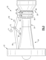
- an active clearance control system 60 directs a fluid, such as air 80, towards a turbine case 61 of the turbine section 28.
- the active clearance system 60 includes a conduit 62 for directing the fluid from either the fan section 22 or the compressor section 24 to a first manifold 64 and a second manifold 66.
- the first and second manifolds 64 and 66 each include multiple openings for directing the fluid towards the turbine section 28.
- the fluid is fed into the conduit 62 by either a first intake 68 or a second intake 70.
- the first intake 68 in this example is in fluid communication with the low pressure compressor 44.
- the second intake 70 is in fluid communication with the high pressure compressor 52.
- a controller 71 directs a valve 72 to communicate fluid from either the first intake 68, the second intake 70, a combination of both the first and second intakes 68 and 70, or blocks the fluid from flowing into the conduit 62.
- valve 72 opens the first intake 68 to direct cooler fluid into the conduit 62.
- the cooler fluid in the conduit 62 then enters the first manifold 64 and the second manifold 66 both adjacent the high pressure turbine 54 in order to shrink the turbine case 61.
- the valve 72 opens the second intake 70 to direct warmer fluid for the compressor section 24 into the conduit 62.
- the warmer fluid in the conduit 62 then enters the first and second manifolds 64 and 66.
- the warmer fluid remaining in the compressor section 24 heats the turbine case 61 to prevent the turbine case 61 from shrinking too quickly from cool air that would be flowing over an exterior of the turbine case 61.
- the warmer fluid from the compressor section 24 prevents interaction between the turbine case 61 and the turbine blades.
- valve 72 opens the second intake 70 to direct warmer fluid from the compressor section 24 into the conduit 62.
- the warmer fluid in the conduit 62 then enters the first and second manifolds 64 and 66.
- the warmer air generated by the compressor section 24 heats the turbine case 61 and reduces the likelihood of any interaction between the turbine blades and the turbine case 61 during startup.
- the warmer air also uniformly heats the turbine case 61 to aid startup.
Landscapes
- Engineering & Computer Science (AREA)
- Mechanical Engineering (AREA)
- General Engineering & Computer Science (AREA)
- Chemical & Material Sciences (AREA)
- Combustion & Propulsion (AREA)
- Structures Of Non-Positive Displacement Pumps (AREA)
Claims (7)
- Procédé de fonctionnement d'un contrôle actif des jeux pour un moteur à turbine à gaz (20) ayant un corps à basse vitesse comportant un arbre interne (40) interconnectant un ventilateur (42), un compresseur basse pression (44) et une turbine basse pression (46) et un corps à grande vitesse comportant un arbre externe (50) interconnectant un compresseur haute pression (52) et une turbine haute pression (54), le procédé comprenant :a) la détermination d'un état de fonctionnement du moteur à turbine à gaz (20) ; etb) la direction d'une première source de fluide en réponse à un premier état de fonctionnement ou une seconde source de fluide en réponse à un second état de fonctionnement vers au moins un collecteur de contrôle actif des jeux (64, 66), dans lequel la première source est une première admission (68) et la seconde source est une seconde admission (70), la seconde admission (70) est configurée pour recevoir du fluide de compresseur provenant du compresseur haute pression (52) et l'au moins un collecteur de contrôle actif des jeux (64, 66) comporte un premier un collecteur (64) et un second collecteur (66) ;caractérisé en ce que :
la première admission (68) est située dans le compresseur basse pression (44), et en ce que le second état de fonctionnement comporte une éolienne. - Procédé selon la revendication 1, dans lequel le premier état de fonctionnement comporte des conditions de croisière.
- Procédé selon la revendication 1 ou 2, dans lequel l'étape b) comporte le déplacement sélectif d'une vanne (72) pour diriger la première source de fluide ou la seconde source de fluide vers l'au moins un collecteur de contrôle actif des jeux (64, 66).
- Procédé selon la revendication 1 ou 2, dans lequel l'étape b) comporte le déplacement sélectif d'une vanne (72) pour diriger une partie de la première source de fluide et une partie de la seconde source de fluide vers l'au moins un collecteur de contrôle actif des jeux (64, 66).
- Procédé selon l'une quelconque des revendications 1 à 4, dans lequel le fait de diriger la première source de fluide vers l'au moins un collecteur de contrôle actif des jeux (64, 66) provoque le rétrécissement d'un boîtier de turbine (61).
- Procédé selon l'une quelconque des revendications 1 à 5, dans lequel le fait de diriger la seconde source de fluide vers l'au moins un collecteur de contrôle actif des jeux (64, 66) provoque la dilatation d'un boîtier de turbine (61).
- Procédé selon l'une quelconque des revendications 1 à 6, dans lequel le premier fluide et le second fluide sont de l'air.
Applications Claiming Priority (2)
| Application Number | Priority Date | Filing Date | Title |
|---|---|---|---|
| US201461972613P | 2014-03-31 | 2014-03-31 | |
| PCT/US2015/021988 WO2015153171A1 (fr) | 2014-03-31 | 2015-03-23 | Contrôle actif des jeux pour moteur à turbine à gaz |
Publications (3)
| Publication Number | Publication Date |
|---|---|
| EP3126640A1 EP3126640A1 (fr) | 2017-02-08 |
| EP3126640A4 EP3126640A4 (fr) | 2017-04-05 |
| EP3126640B1 true EP3126640B1 (fr) | 2024-09-25 |
Family
ID=54241105
Family Applications (1)
| Application Number | Title | Priority Date | Filing Date |
|---|---|---|---|
| EP15773710.7A Active EP3126640B1 (fr) | 2014-03-31 | 2015-03-23 | Contrôle actif des jeux pour moteur à turbine à gaz |
Country Status (3)
| Country | Link |
|---|---|
| US (1) | US20170074112A1 (fr) |
| EP (1) | EP3126640B1 (fr) |
| WO (1) | WO2015153171A1 (fr) |
Families Citing this family (8)
| Publication number | Priority date | Publication date | Assignee | Title |
|---|---|---|---|---|
| US10247029B2 (en) * | 2016-02-04 | 2019-04-02 | United Technologies Corporation | Method for clearance control in a gas turbine engine |
| GB2552048A (en) * | 2016-03-22 | 2018-01-10 | Gen Electric | Method, system, and apparatus for reducing a turbine clearance |
| US10914185B2 (en) * | 2016-12-02 | 2021-02-09 | General Electric Company | Additive manufactured case with internal passages for active clearance control |
| DE102017216119A1 (de) | 2017-09-13 | 2019-03-14 | MTU Aero Engines AG | Gasturbinenverdichtergehäuse |
| US10927696B2 (en) * | 2018-10-19 | 2021-02-23 | Raytheon Technologies Corporation | Compressor case clearance control logic |
| US11512594B2 (en) | 2020-06-05 | 2022-11-29 | General Electric Company | System and method for modulating airflow into a bore of a rotor to control blade tip clearance |
| US20250334055A1 (en) * | 2024-04-24 | 2025-10-30 | General Electric Company | Gas turbine engine having cooling systems |
| US20250389226A1 (en) * | 2024-04-24 | 2025-12-25 | General Electric Company | Gas turbine engine having cooling systems |
Citations (2)
| Publication number | Priority date | Publication date | Assignee | Title |
|---|---|---|---|---|
| US4230439A (en) * | 1978-07-17 | 1980-10-28 | General Electric Company | Air delivery system for regulating thermal growth |
| EP1038093B1 (fr) * | 1997-12-11 | 2002-05-22 | Pratt & Whitney Canada Corp. | Soupape thermique passive de turbine ameliorant la regulation du jeu a l'extremite |
Family Cites Families (9)
| Publication number | Priority date | Publication date | Assignee | Title |
|---|---|---|---|---|
| US4525998A (en) * | 1982-08-02 | 1985-07-02 | United Technologies Corporation | Clearance control for gas turbine engine |
| GB2195715B (en) * | 1986-10-08 | 1990-10-10 | Rolls Royce Plc | Gas turbine engine rotor blade clearance control |
| FR2614073B1 (fr) * | 1987-04-15 | 1992-02-14 | Snecma | Dispositif d'ajustement en temps reel du jeu radial entre un rotor et un stator de turbomachine |
| US6487491B1 (en) * | 2001-11-21 | 2002-11-26 | United Technologies Corporation | System and method of controlling clearance between turbine engine blades and case based on engine components thermal growth model |
| EP2138676B1 (fr) * | 2008-06-24 | 2013-01-30 | Siemens Aktiengesellschaft | Procédé et dispositif de refroidissement d'un carter de turbine à gaz |
| US8668431B2 (en) * | 2010-03-29 | 2014-03-11 | United Technologies Corporation | Seal clearance control on non-cowled gas turbine engines |
| GB201113165D0 (en) * | 2011-08-01 | 2011-09-14 | Rolls Royce Plc | A tip clearance control device |
| US9157331B2 (en) * | 2011-12-08 | 2015-10-13 | Siemens Aktiengesellschaft | Radial active clearance control for a gas turbine engine |
| US9260974B2 (en) * | 2011-12-16 | 2016-02-16 | General Electric Company | System and method for active clearance control |
-
2015
- 2015-03-23 US US15/123,940 patent/US20170074112A1/en not_active Abandoned
- 2015-03-23 EP EP15773710.7A patent/EP3126640B1/fr active Active
- 2015-03-23 WO PCT/US2015/021988 patent/WO2015153171A1/fr not_active Ceased
Patent Citations (2)
| Publication number | Priority date | Publication date | Assignee | Title |
|---|---|---|---|---|
| US4230439A (en) * | 1978-07-17 | 1980-10-28 | General Electric Company | Air delivery system for regulating thermal growth |
| EP1038093B1 (fr) * | 1997-12-11 | 2002-05-22 | Pratt & Whitney Canada Corp. | Soupape thermique passive de turbine ameliorant la regulation du jeu a l'extremite |
Also Published As
| Publication number | Publication date |
|---|---|
| EP3126640A4 (fr) | 2017-04-05 |
| WO2015153171A1 (fr) | 2015-10-08 |
| EP3126640A1 (fr) | 2017-02-08 |
| US20170074112A1 (en) | 2017-03-16 |
Similar Documents
| Publication | Publication Date | Title |
|---|---|---|
| EP3296543B1 (fr) | Moteur à turbine à gaz avec air de refroidissement refroidi et entraînement de turbine | |
| EP3126640B1 (fr) | Contrôle actif des jeux pour moteur à turbine à gaz | |
| EP2952681B1 (fr) | Refroidissement d'un etage de turbine et procédé correspondant | |
| EP2900957B1 (fr) | Vanne d'antigivrage de nacelle servant de vanne de prélèvement de stabilité de compresseur pendant un démarrage | |
| US9932905B2 (en) | Bypass duct heat exchanger with controlled fan | |
| US10794291B2 (en) | Geared turbofan architecture for regional jet aircraft | |
| EP2927433B1 (fr) | Contrôle actif de jeu pour moteur de turbine à gaz | |
| EP3039264B1 (fr) | Agencement de refroidissement et de mélange de diffuseur de turbine à gaz | |
| EP2949883B1 (fr) | Système de lubrification de moteur de turbine à gaz | |
| EP3060760B1 (fr) | Profil aérodynamique à refroidissement de structure peau-coeur | |
| EP3348810B1 (fr) | Système d'air de refroidissement refroidi par injection pour moteur à turbine à gaz et procédé correspondant | |
| EP3094823B1 (fr) | Composant de moteur à turbine à gaz et moteur à turbine à gaz associé | |
| EP3805527B1 (fr) | Air de refroidissement refroidi pour joint d'air de lame à travers une chambre externe | |
| EP3330515B1 (fr) | Moteur à turbine à gaz | |
| EP2993301B1 (fr) | Structure de moteur à turbine à gaz, moteur à turbine à gaz et procédé pour conduire un réfrigérant à travers un trajet d'écoulement dans un moteur à turbine à gaz. | |
| EP2959149B1 (fr) | Partie centrale de moteur à turbine à gaz utilisée à la fois dans des moteurs militaires ou commerciaux | |
| EP3388637B1 (fr) | Chambre d'air de refroidissement pour joint d'air extérieur d'aube | |
| EP3388625B1 (fr) | Air de refroidissement refroidi vers un joint d'air extérieur d'aubes à travers une aube de stator | |
| EP3358152B1 (fr) | Chambre de mélange externe pour moteur à turbine à gaz avec de l'air de refroidissement de turbine refroidi | |
| EP3181869B1 (fr) | Refroidissement de diamètre interne de compresseur | |
| EP3348812B1 (fr) | Air de refroidissement de moteur à turbine à gaz avec décharge d'air froid |
Legal Events
| Date | Code | Title | Description |
|---|---|---|---|
| STAA | Information on the status of an ep patent application or granted ep patent |
Free format text: STATUS: THE INTERNATIONAL PUBLICATION HAS BEEN MADE |
|
| PUAI | Public reference made under article 153(3) epc to a published international application that has entered the european phase |
Free format text: ORIGINAL CODE: 0009012 |
|
| STAA | Information on the status of an ep patent application or granted ep patent |
Free format text: STATUS: REQUEST FOR EXAMINATION WAS MADE |
|
| 17P | Request for examination filed |
Effective date: 20161031 |
|
| AK | Designated contracting states |
Kind code of ref document: A1 Designated state(s): AL AT BE BG CH CY CZ DE DK EE ES FI FR GB GR HR HU IE IS IT LI LT LU LV MC MK MT NL NO PL PT RO RS SE SI SK SM TR |
|
| AX | Request for extension of the european patent |
Extension state: BA ME |
|
| A4 | Supplementary search report drawn up and despatched |
Effective date: 20170308 |
|
| RIC1 | Information provided on ipc code assigned before grant |
Ipc: F01D 11/24 20060101AFI20170302BHEP Ipc: F02C 7/18 20060101ALI20170302BHEP |
|
| DAV | Request for validation of the european patent (deleted) | ||
| DAX | Request for extension of the european patent (deleted) | ||
| STAA | Information on the status of an ep patent application or granted ep patent |
Free format text: STATUS: EXAMINATION IS IN PROGRESS |
|
| 17Q | First examination report despatched |
Effective date: 20180412 |
|
| RAP1 | Party data changed (applicant data changed or rights of an application transferred) |
Owner name: RAYTHEON TECHNOLOGIES CORPORATION |
|
| RAP3 | Party data changed (applicant data changed or rights of an application transferred) |
Owner name: RTX CORPORATION |
|
| REG | Reference to a national code |
Ref country code: DE Ref legal event code: R079 Free format text: PREVIOUS MAIN CLASS: F01D0011240000 Ipc: F01D0011220000 Ref country code: DE Ref legal event code: R079 Ref document number: 602015089979 Country of ref document: DE Free format text: PREVIOUS MAIN CLASS: F01D0011240000 Ipc: F01D0011220000 |
|
| RIC1 | Information provided on ipc code assigned before grant |
Ipc: F02C 7/18 20060101ALI20240308BHEP Ipc: F01D 11/24 20060101ALI20240308BHEP Ipc: F02C 3/13 20060101ALI20240308BHEP Ipc: F01D 11/22 20060101AFI20240308BHEP |
|
| GRAP | Despatch of communication of intention to grant a patent |
Free format text: ORIGINAL CODE: EPIDOSNIGR1 |
|
| STAA | Information on the status of an ep patent application or granted ep patent |
Free format text: STATUS: GRANT OF PATENT IS INTENDED |
|
| INTG | Intention to grant announced |
Effective date: 20240419 |
|
| GRAS | Grant fee paid |
Free format text: ORIGINAL CODE: EPIDOSNIGR3 |
|
| GRAA | (expected) grant |
Free format text: ORIGINAL CODE: 0009210 |
|
| STAA | Information on the status of an ep patent application or granted ep patent |
Free format text: STATUS: THE PATENT HAS BEEN GRANTED |
|
| AK | Designated contracting states |
Kind code of ref document: B1 Designated state(s): AL AT BE BG CH CY CZ DE DK EE ES FI FR GB GR HR HU IE IS IT LI LT LU LV MC MK MT NL NO PL PT RO RS SE SI SK SM TR |
|
| REG | Reference to a national code |
Ref country code: GB Ref legal event code: FG4D |
|
| REG | Reference to a national code |
Ref country code: CH Ref legal event code: EP |
|
| REG | Reference to a national code |
Ref country code: DE Ref legal event code: R096 Ref document number: 602015089979 Country of ref document: DE |
|
| REG | Reference to a national code |
Ref country code: IE Ref legal event code: FG4D |
|
| REG | Reference to a national code |
Ref country code: LT Ref legal event code: MG9D |
|
| PG25 | Lapsed in a contracting state [announced via postgrant information from national office to epo] |
Ref country code: NO Free format text: LAPSE BECAUSE OF FAILURE TO SUBMIT A TRANSLATION OF THE DESCRIPTION OR TO PAY THE FEE WITHIN THE PRESCRIBED TIME-LIMIT Effective date: 20241225 |
|
| PG25 | Lapsed in a contracting state [announced via postgrant information from national office to epo] |
Ref country code: GR Free format text: LAPSE BECAUSE OF FAILURE TO SUBMIT A TRANSLATION OF THE DESCRIPTION OR TO PAY THE FEE WITHIN THE PRESCRIBED TIME-LIMIT Effective date: 20241226 Ref country code: FI Free format text: LAPSE BECAUSE OF FAILURE TO SUBMIT A TRANSLATION OF THE DESCRIPTION OR TO PAY THE FEE WITHIN THE PRESCRIBED TIME-LIMIT Effective date: 20240925 |
|
| PG25 | Lapsed in a contracting state [announced via postgrant information from national office to epo] |
Ref country code: BG Free format text: LAPSE BECAUSE OF FAILURE TO SUBMIT A TRANSLATION OF THE DESCRIPTION OR TO PAY THE FEE WITHIN THE PRESCRIBED TIME-LIMIT Effective date: 20240925 |
|
| PG25 | Lapsed in a contracting state [announced via postgrant information from national office to epo] |
Ref country code: LV Free format text: LAPSE BECAUSE OF FAILURE TO SUBMIT A TRANSLATION OF THE DESCRIPTION OR TO PAY THE FEE WITHIN THE PRESCRIBED TIME-LIMIT Effective date: 20240925 |
|
| PG25 | Lapsed in a contracting state [announced via postgrant information from national office to epo] |
Ref country code: RS Free format text: LAPSE BECAUSE OF FAILURE TO SUBMIT A TRANSLATION OF THE DESCRIPTION OR TO PAY THE FEE WITHIN THE PRESCRIBED TIME-LIMIT Effective date: 20241225 |
|
| REG | Reference to a national code |
Ref country code: NL Ref legal event code: MP Effective date: 20240925 |
|
| PG25 | Lapsed in a contracting state [announced via postgrant information from national office to epo] |
Ref country code: RS Free format text: LAPSE BECAUSE OF FAILURE TO SUBMIT A TRANSLATION OF THE DESCRIPTION OR TO PAY THE FEE WITHIN THE PRESCRIBED TIME-LIMIT Effective date: 20241225 Ref country code: NO Free format text: LAPSE BECAUSE OF FAILURE TO SUBMIT A TRANSLATION OF THE DESCRIPTION OR TO PAY THE FEE WITHIN THE PRESCRIBED TIME-LIMIT Effective date: 20241225 Ref country code: LV Free format text: LAPSE BECAUSE OF FAILURE TO SUBMIT A TRANSLATION OF THE DESCRIPTION OR TO PAY THE FEE WITHIN THE PRESCRIBED TIME-LIMIT Effective date: 20240925 Ref country code: GR Free format text: LAPSE BECAUSE OF FAILURE TO SUBMIT A TRANSLATION OF THE DESCRIPTION OR TO PAY THE FEE WITHIN THE PRESCRIBED TIME-LIMIT Effective date: 20241226 Ref country code: FI Free format text: LAPSE BECAUSE OF FAILURE TO SUBMIT A TRANSLATION OF THE DESCRIPTION OR TO PAY THE FEE WITHIN THE PRESCRIBED TIME-LIMIT Effective date: 20240925 Ref country code: BG Free format text: LAPSE BECAUSE OF FAILURE TO SUBMIT A TRANSLATION OF THE DESCRIPTION OR TO PAY THE FEE WITHIN THE PRESCRIBED TIME-LIMIT Effective date: 20240925 |
|
| REG | Reference to a national code |
Ref country code: AT Ref legal event code: MK05 Ref document number: 1726786 Country of ref document: AT Kind code of ref document: T Effective date: 20240925 |
|
| PG25 | Lapsed in a contracting state [announced via postgrant information from national office to epo] |
Ref country code: NL Free format text: LAPSE BECAUSE OF FAILURE TO SUBMIT A TRANSLATION OF THE DESCRIPTION OR TO PAY THE FEE WITHIN THE PRESCRIBED TIME-LIMIT Effective date: 20240925 |
|
| PG25 | Lapsed in a contracting state [announced via postgrant information from national office to epo] |
Ref country code: PT Free format text: LAPSE BECAUSE OF FAILURE TO SUBMIT A TRANSLATION OF THE DESCRIPTION OR TO PAY THE FEE WITHIN THE PRESCRIBED TIME-LIMIT Effective date: 20250127 Ref country code: IS Free format text: LAPSE BECAUSE OF FAILURE TO SUBMIT A TRANSLATION OF THE DESCRIPTION OR TO PAY THE FEE WITHIN THE PRESCRIBED TIME-LIMIT Effective date: 20250125 |
|
| PG25 | Lapsed in a contracting state [announced via postgrant information from national office to epo] |
Ref country code: RO Free format text: LAPSE BECAUSE OF FAILURE TO SUBMIT A TRANSLATION OF THE DESCRIPTION OR TO PAY THE FEE WITHIN THE PRESCRIBED TIME-LIMIT Effective date: 20240925 Ref country code: SM Free format text: LAPSE BECAUSE OF FAILURE TO SUBMIT A TRANSLATION OF THE DESCRIPTION OR TO PAY THE FEE WITHIN THE PRESCRIBED TIME-LIMIT Effective date: 20240925 |
|
| PG25 | Lapsed in a contracting state [announced via postgrant information from national office to epo] |
Ref country code: ES Free format text: LAPSE BECAUSE OF FAILURE TO SUBMIT A TRANSLATION OF THE DESCRIPTION OR TO PAY THE FEE WITHIN THE PRESCRIBED TIME-LIMIT Effective date: 20240925 |
|
| PG25 | Lapsed in a contracting state [announced via postgrant information from national office to epo] |
Ref country code: EE Free format text: LAPSE BECAUSE OF FAILURE TO SUBMIT A TRANSLATION OF THE DESCRIPTION OR TO PAY THE FEE WITHIN THE PRESCRIBED TIME-LIMIT Effective date: 20240925 Ref country code: AT Free format text: LAPSE BECAUSE OF FAILURE TO SUBMIT A TRANSLATION OF THE DESCRIPTION OR TO PAY THE FEE WITHIN THE PRESCRIBED TIME-LIMIT Effective date: 20240925 |
|
| PG25 | Lapsed in a contracting state [announced via postgrant information from national office to epo] |
Ref country code: PL Free format text: LAPSE BECAUSE OF FAILURE TO SUBMIT A TRANSLATION OF THE DESCRIPTION OR TO PAY THE FEE WITHIN THE PRESCRIBED TIME-LIMIT Effective date: 20240925 Ref country code: CZ Free format text: LAPSE BECAUSE OF FAILURE TO SUBMIT A TRANSLATION OF THE DESCRIPTION OR TO PAY THE FEE WITHIN THE PRESCRIBED TIME-LIMIT Effective date: 20240925 |
|
| PG25 | Lapsed in a contracting state [announced via postgrant information from national office to epo] |
Ref country code: SK Free format text: LAPSE BECAUSE OF FAILURE TO SUBMIT A TRANSLATION OF THE DESCRIPTION OR TO PAY THE FEE WITHIN THE PRESCRIBED TIME-LIMIT Effective date: 20240925 Ref country code: IT Free format text: LAPSE BECAUSE OF FAILURE TO SUBMIT A TRANSLATION OF THE DESCRIPTION OR TO PAY THE FEE WITHIN THE PRESCRIBED TIME-LIMIT Effective date: 20240925 |
|
| REG | Reference to a national code |
Ref country code: DE Ref legal event code: R097 Ref document number: 602015089979 Country of ref document: DE |
|
| PG25 | Lapsed in a contracting state [announced via postgrant information from national office to epo] |
Ref country code: DK Free format text: LAPSE BECAUSE OF FAILURE TO SUBMIT A TRANSLATION OF THE DESCRIPTION OR TO PAY THE FEE WITHIN THE PRESCRIBED TIME-LIMIT Effective date: 20240925 |
|
| PLBE | No opposition filed within time limit |
Free format text: ORIGINAL CODE: 0009261 |
|
| STAA | Information on the status of an ep patent application or granted ep patent |
Free format text: STATUS: NO OPPOSITION FILED WITHIN TIME LIMIT |
|
| 26N | No opposition filed |
Effective date: 20250626 |
|
| PG25 | Lapsed in a contracting state [announced via postgrant information from national office to epo] |
Ref country code: SE Free format text: LAPSE BECAUSE OF FAILURE TO SUBMIT A TRANSLATION OF THE DESCRIPTION OR TO PAY THE FEE WITHIN THE PRESCRIBED TIME-LIMIT Effective date: 20240925 |
|
| PG25 | Lapsed in a contracting state [announced via postgrant information from national office to epo] |
Ref country code: MC Free format text: LAPSE BECAUSE OF FAILURE TO SUBMIT A TRANSLATION OF THE DESCRIPTION OR TO PAY THE FEE WITHIN THE PRESCRIBED TIME-LIMIT Effective date: 20240925 |
|
| REG | Reference to a national code |
Ref country code: CH Ref legal event code: H13 Free format text: ST27 STATUS EVENT CODE: U-0-0-H10-H13 (AS PROVIDED BY THE NATIONAL OFFICE) Effective date: 20251024 |
|
| PG25 | Lapsed in a contracting state [announced via postgrant information from national office to epo] |
Ref country code: LU Free format text: LAPSE BECAUSE OF NON-PAYMENT OF DUE FEES Effective date: 20250323 |
|
| REG | Reference to a national code |
Ref country code: BE Ref legal event code: MM Effective date: 20250331 |
|
| PG25 | Lapsed in a contracting state [announced via postgrant information from national office to epo] |
Ref country code: HR Free format text: LAPSE BECAUSE OF FAILURE TO SUBMIT A TRANSLATION OF THE DESCRIPTION OR TO PAY THE FEE WITHIN THE PRESCRIBED TIME-LIMIT Effective date: 20240925 |
|
| PG25 | Lapsed in a contracting state [announced via postgrant information from national office to epo] |
Ref country code: BE Free format text: LAPSE BECAUSE OF NON-PAYMENT OF DUE FEES Effective date: 20250331 |
|
| PG25 | Lapsed in a contracting state [announced via postgrant information from national office to epo] |
Ref country code: CH Free format text: LAPSE BECAUSE OF NON-PAYMENT OF DUE FEES Effective date: 20250331 |
|
| PG25 | Lapsed in a contracting state [announced via postgrant information from national office to epo] |
Ref country code: IE Free format text: LAPSE BECAUSE OF NON-PAYMENT OF DUE FEES Effective date: 20250323 |
|
| PGFP | Annual fee paid to national office [announced via postgrant information from national office to epo] |
Ref country code: GB Payment date: 20260220 Year of fee payment: 12 |
|
| PGFP | Annual fee paid to national office [announced via postgrant information from national office to epo] |
Ref country code: DE Payment date: 20260219 Year of fee payment: 12 |
|
| PGFP | Annual fee paid to national office [announced via postgrant information from national office to epo] |
Ref country code: FR Payment date: 20260219 Year of fee payment: 12 |