EP3126692B1 - Élément ressort pour dispositif de friction - Google Patents
Élément ressort pour dispositif de friction Download PDFInfo
- Publication number
- EP3126692B1 EP3126692B1 EP15744846.5A EP15744846A EP3126692B1 EP 3126692 B1 EP3126692 B1 EP 3126692B1 EP 15744846 A EP15744846 A EP 15744846A EP 3126692 B1 EP3126692 B1 EP 3126692B1
- Authority
- EP
- European Patent Office
- Prior art keywords
- spring element
- receiving
- element body
- body part
- friction
- Prior art date
- Legal status (The legal status is an assumption and is not a legal conclusion. Google has not performed a legal analysis and makes no representation as to the accuracy of the status listed.)
- Not-in-force
Links
Images


Classifications
-
- F—MECHANICAL ENGINEERING; LIGHTING; HEATING; WEAPONS; BLASTING
- F16—ENGINEERING ELEMENTS AND UNITS; GENERAL MEASURES FOR PRODUCING AND MAINTAINING EFFECTIVE FUNCTIONING OF MACHINES OR INSTALLATIONS; THERMAL INSULATION IN GENERAL
- F16D—COUPLINGS FOR TRANSMITTING ROTATION; CLUTCHES; BRAKES
- F16D13/00—Friction clutches
- F16D13/58—Details
- F16D13/60—Clutching elements
- F16D13/64—Clutch-plates; Clutch-lamellae
-
- F—MECHANICAL ENGINEERING; LIGHTING; HEATING; WEAPONS; BLASTING
- F16—ENGINEERING ELEMENTS AND UNITS; GENERAL MEASURES FOR PRODUCING AND MAINTAINING EFFECTIVE FUNCTIONING OF MACHINES OR INSTALLATIONS; THERMAL INSULATION IN GENERAL
- F16D—COUPLINGS FOR TRANSMITTING ROTATION; CLUTCHES; BRAKES
- F16D13/00—Friction clutches
- F16D13/58—Details
- F16D13/70—Pressure members, e.g. pressure plates, for clutch-plates or lamellae; Guiding arrangements for pressure members
-
- F—MECHANICAL ENGINEERING; LIGHTING; HEATING; WEAPONS; BLASTING
- F16—ENGINEERING ELEMENTS AND UNITS; GENERAL MEASURES FOR PRODUCING AND MAINTAINING EFFECTIVE FUNCTIONING OF MACHINES OR INSTALLATIONS; THERMAL INSULATION IN GENERAL
- F16D—COUPLINGS FOR TRANSMITTING ROTATION; CLUTCHES; BRAKES
- F16D69/00—Friction linings; Attachment thereof; Selection of coacting friction substances or surfaces
- F16D69/04—Attachment of linings
-
- F—MECHANICAL ENGINEERING; LIGHTING; HEATING; WEAPONS; BLASTING
- F16—ENGINEERING ELEMENTS AND UNITS; GENERAL MEASURES FOR PRODUCING AND MAINTAINING EFFECTIVE FUNCTIONING OF MACHINES OR INSTALLATIONS; THERMAL INSULATION IN GENERAL
- F16D—COUPLINGS FOR TRANSMITTING ROTATION; CLUTCHES; BRAKES
- F16D13/00—Friction clutches
- F16D13/58—Details
- F16D13/60—Clutching elements
- F16D13/64—Clutch-plates; Clutch-lamellae
- F16D2013/642—Clutch-plates; Clutch-lamellae with resilient attachment of frictions rings or linings to their supporting discs or plates for allowing limited axial displacement of these rings or linings
Definitions
- the invention relates to a spring element for a friction device, in particular a clutch disc for a friction clutch comprising a spring element body having a first spring element body part and a second spring element body part, which are arranged one behind the other in the axial direction and partially abut each other, each spring element body part arranged in a circumferential direction next to each other Has receiving areas for friction linings, so that the friction linings can be arranged on both sides of the spring element body and fixed on this.
- the invention relates to a friction device, in particular a clutch disc for a friction clutch, comprising a disc-shaped base body with a support element, wherein the support member has an outer circumference, distributed over the plurality of friction groups are arranged, wherein the friction groups each have a first friction lining and one in the axial direction have behind arranged second friction lining.
- Each lining carrier has corresponding apertures in the region of the projection of the fastening rivets of the opposite lining carrier.
- the versions of the friction linings also congruent with the lining carriers breakthroughs.
- At least one spacer rivet for pretensioning the lining carrier is arranged between the two lining carriers on the symmetry line.
- the arrangement of the friction linings on resilient lining carriers takes place predominantly, so that the metallic or metal-ceramic friction linings undergo no impacts or impacts when they are engaged, as a result of which these friction linings suffer prematurely from damage.
- Such metallic or metal-ceramic friction linings are in fact significantly less elastic compared to other friction linings, for example of resin-bonded fibers.
- these metallic or metal-ceramic friction linings offer the advantage, in comparison with other friction linings, that higher torques can thus be transmitted. With the resilient arrangement of the friction linings but also the metering of the clutch can be improved during engagement.
- a clutch disc From the US 5,857,551 A Various embodiments of a clutch disc are known.
- the friction linings are arranged distributed on three friction groups, wherein two friction linings are arranged side by side on the lining carriers in the circumferential direction, as is the case Fig. 2 of the US 5,857,551 A is apparent. It will be in this embodiment of the clutch disc after the US 5,857,551 A not two friction linings each arranged on separate, wing-like lining carriers, as described in the above DE 29 20 095 A1 the case is.
- the friction linings are in this first embodiment of the clutch disc after the US 5,857,551 A fastened on the one hand by caulking with the lining carriers and on the other hand by riveting, wherein the actual friction linings are sintered even on friction lining carriers.
- the Reibbelag uman with the pad carriers latter are bent over on three sides and further have a bent tab, so that the Reibbelagedia are all sides positively connected to the pad carriers.
- the friction linings are resilient on the one hand, as in the DE 29 20 095 A1 described, and on the other hand fixed rigidly over the caulking.
- the US 5,857,551 A describes yet another embodiment of a clutch disc, in analogy to DE 29 20 095 A1 two friction linings each are arranged on separate, wing-like lining carriers.
- the in Fig. 5 of the US 5,857,551 A is shown, so the pad carrier only about half as large as at the first embodiment.
- Connected with this describes the US 5,857,551 A in that all the friction linings are resiliently fastened, as already described in US Pat DE 29 20 095 A1 is known. It is therefore departed from the rigid attachment of a part of the friction linings.
- the present invention has for its object to improve a clutch disc of the type mentioned above or generally a friction device, in particular with regard to their friction behavior.
- the first spring element body part and the second spring element body part are at least approximately annular and that per receiving area for the friction linings a first receiving lug and a second receiving lug are formed, wherein the first receiving lug is arranged in the radial direction below the second receiving lug and wherein, in particular, the first receiving lug and the second receiving lug of each friction pad receiving area of the first spring element body part are formed by the first spring element body part and the first receiving lug and the second receiving lug of each friction lining receiving area of the second spring element body part is formed by the second spring element body part.
- the friction device for solving the problem that the first and second friction linings are connected to a spring element according to the invention, optionally with interposition of a respective Reibbelagschis, and the spring element is connected to the carrier element, and wherein the spring element between the first and the second friction linings is arranged, and that per receiving area for the friction linings a first receiving lug and a second receiving lug are formed, wherein the first Aufnamelasche is arranged in the radial direction below the second receiving lug.
- the spring element a speed-robust design of a clutch disc or a friction device is achieved.
- the tilting moment, resulting from the centrifugal force of the individual segments, ie the Einzelreibbeläge is supported in the present construction by two separate tabs, wherein the lower flap is loaded to train and thus represents a high rigidity against the tilting moment.
- the deflection of the spring tabs, ie the receiving lugs is thus very low in terms of speed of rotation compared with the prior art.
- the coupling modulation at different speeds can be designed almost the same become. Due to the individual suspension for each friction lining, a very homogeneous contact pattern for the friction linings can be achieved. Due to the arrangement of two receiving lugs per friction lining better adjustability of the rigidity of the friction device can be achieved.
- the first receiving lugs of the first spring element body part respectively at least partially in a recess of the first spring element body and / or the first receiving latches of the second spring element body part respectively at least partially are arranged in a recess of the second spring element body.
- the measures no or at least almost no influence on the torsional and bending stiffness of the friction device to pull. It is thus further possible to set different spring travel for at least one of the friction linings, so that at least individual friction linings engage in different release paths with the counterstay element or the counterstay device.
- the two spring element body parts are each formed in one piece, whereby the entire spring element can be given at least approximately over the entire surface constant basic stiffness, so that the adjustment of the stiffness behavior of the friction linings when meshing, i. the receiving lugs for the friction linings, can be done easier and more accurate.
- the first spring element body part has a wall thickness at least in the region of the receiving lugs
- the second spring element body part has a wall thickness at least in the area of the receiving lugs, the wall thickness in the region of at least one of the receiving lugs of the first spring element body part compared to the wall thickness in the region Area of the receiving lugs of the second spring element body part is smaller.
- Fig. 1 is a friction device in the form of a clutch disc 1 for a known per se from the prior art friction clutch.
- the clutch disc 1 is the preferred embodiment of the friction device.
- other friction devices are also possible within the scope of the invention, such as e.g. Brakes or generally preload elements (in the form of a disc spring).
- the clutch disc 1 may substantially correspond to those known in the art. Essentially, it is meant that - as will be explained in more detail below - there are differences in the structure with respect to the arrangement of friction linings 2, 3 and a spring element 4.
- the clutch disc 1 has a, in particular disc-shaped, main body 5. On or in the main body 5 a plurality of torsion springs 6 are arranged. However, the arrangement of the torsion springs 6 is not absolutely necessary, so that their arrangement in the clutch disc 1 is only optional. In addition, a recess 7 is centrally formed for receiving a shaft, not shown. Since this is known in principle from the prior art, reference is made to the relevant literature for details.
- the main body 5 comprises a disc-shaped carrier element 8.
- the carrier element 8 is arranged at least in the region of an outer circumference 9 of the main body 5.
- the carrier element 8 can extend over the surface-viewed in the axial direction-the entire main body 5, that is, from the recess 7 to the outer circumference 9.
- the recess 7 can thus also be formed in the carrier element 8.
- the torsion springs 6 (also) may be arranged in corresponding receptacles in the carrier element 8.
- the carrier element 8 is annular and is arranged only in the region of the circumference 9, so that it does not extend radially into the region of the recess 7.
- cover elements are arranged at least in regions.
- the carrier element 8 is made of a metal sheet, in particular a steel sheet.
- the carrier element 8 is formed in one piece, that is not composed of several parts.
- the spring element 4 is provided.
- the spring element 4 has a spring element body 10.
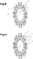
- This spring element body 10 consists of a first spring element body part 11, which in Fig. 2 is shown, and a second spring element body part 12, the in Fig. 3 is shown, or has the first and the second spring element body part 11, 12.
- the two spring element body parts 11, 12 are at least approximately annular. It is preferred if the two spring element body parts 11, 12 are each formed in one piece, in particular as stamped parts. According to a non-preferred embodiment of the spring element 4 but at least one, for example, both spring element body parts 11, 12 may be formed in several parts, the individual parts to form the respective spring element body part 11 and 12 or the two annular spring element body parts 11, 12 connected to each other are.
- the friction linings 2, 3 are not ring-like, ie formed as a closed ring as the spring element body 11, 12, but are arranged side by side in the form of discrete segments in the circumferential direction 14 and spaced from each other. As in particular from Fig. 5 it can be seen, the friction linings 2, 3 are respectively arranged on both sides of the spring element 4. It is in the axial direction in each case a friction lining 2 is arranged behind a friction lining 3.
- the friction linings are each arranged alternately on the spring element body parts 11, 12 next to each other.
- a friction lining 2 and a friction lining 3 form a friction group 16 or 17 as shown Fig. 5 is apparent.
- each one of the friction linings 2 in the axial direction congruent with one of further friction linings 2 and one of the friction linings 3 in the axial direction congruent with each one of further friction linings 3 is so that in each case two friction linings 2 and two friction linings 3 form a friction group 16 and 17, respectively.
- the spring element body parts 11, 12 are connected to the carrier element 8.
- bores are preferably provided both in the spring element body parts 11, 12 and in the carrier element 8, so that the spring element body parts 11, 12 are connected to the carrier element 8 via a plurality of rivets 18 which extend through these bores.
- the fixation ie the connection of the spring element body parts 11, 12 with the carrier element 8 can also be non-positively and / or materially and / or positively, for example by the carrier element. 8 facing end portion of the spring element body parts 11, 12 is bent at least approximately at 90 ° and is inserted in a corresponding slot-shaped receptacle of the support element 8.
- the two spring element body parts 11, 12 are arranged on one side (viewed in the axial direction) of the carrier element 8, as shown in the figures. But there is also the possibility that the carrier element 8 is partially disposed between the two spring element body parts 11,12.
- the carrier element 8 does not extend to the outer periphery or the outer diameter of the clutch disc 1.
- Each spring element body part 11, 12 has only on one side - viewed in the axial direction - the friction linings 2, 3, so that the two spring element body parts 11, 12 are arranged in the axial direction between the friction linings 2, 3, as for example Fig. 5 is apparent.
- the two spring element body parts 11, 12 in the axial direction are preferably directly behind one another, wherein the two spring element body parts 11, 12 abut each other only partially, as for example Fig. 4 can be seen and will be explained in more detail below.
- the spring element 4 has per receiving area 15 at least two, in particular only two, receiving lugs, namely a first receiving lug 19 and a second receiving lug 20, on.
- These receiving lugs 19, 20 are split over the two spring element body parts 11, 12.
- two first receiving lugs 19 and in each case two second receiving lugs 19 are arranged in succession in the axial direction per friction group 16, 17.
- these receiving lugs 19, 20 are integrally formed with the spring element body 11 or 12 or formed from this.
- the receiving lugs 19, 20 each form their own components which are connected to the spring element body parts 11, 12, for example via rivets or screws and / or cohesively, such. welded or soldered or glued, and / or form-fitting.
- two receiving lugs 19 and two receiving lugs 20 are arranged one behind the other.
- the receiving lugs arranged one behind the other can each be the same size, but they can also have a different size, as will be described in more detail below.
- the first receiving lugs 19 are arranged below the second receiving lugs 20 viewed in the radial direction.
- the spring element 4 thus has radially inner receiving lugs 19 and radially outer receiving lugs 20 for friction linings 2, 3.
- the two spring element body parts 11, 12 are preferably connected to one another, ie that the spring element body parts 11, 12 are connected not only in the region of the carrier element 8 via the rivets 18 with the carrier element 8 and thus also with each other, but that additional rivets 21 are provided over the two spring element body parts 11, 12 are interconnected.
- These rivets 21 are preferably not arranged in the region of the receiving lugs 19, 20, but viewed in the circumferential direction 14 next to the receiving lugs 19, 20, as in particular from the 4 and 5 is apparent.
- connection of the spring element body parts 11, 12 may also be cohesively, in particular by welding, or by gluing, and / or positively locking, e.g. by folding, done.
- the two spring element body parts 11, 12 lie against each other only in regions. In the region of the receiving lugs 11, 12 they are at least partially spaced from each other, whereby the spring action of the receiving lugs 11, 12 is formed under pressure. To form this spacing, the receiving lugs 19 and 20 of the first spring element body part 11 are bent forward in the axial direction out of the plane of the first spring element body part 11 and the receiving lugs 19 and 20 of the second spring element body part 12 in the axial direction to the rear out of the plane of the second spring element body part 11 bent out.
- the receiving tabs 19, starting from a base 22 in Fig.
- a first oblique flap part 23 (obliquely with respect to the plane of the first spring element body part 11 and second spring element body part 12 perpendicular to the axial direction of the clutch disc 1) and an adjoining second flap part 24 which is at least approximately parallel to the plane of the first spring element body part 11 or second spring element body part 12 runs perpendicular to the axial direction of the clutch disc 1.
- the second receiving lugs 20 starting from a base 25 (in Fig.
- first inclined tab portion 26 (obliquely with respect to the plane of the first spring member body part 11 and second spring element body part 12 perpendicular to the axial direction of the clutch disc 1) and an adjoining second tab portion 27, at least approximately parallel to the plane of the first spring element body part eleventh or second spring element body part 12 is perpendicular to the axial direction of the clutch disc 1.
- the base 22 and the base 25 are respectively formed in the radial direction below the lug parts 23 and 27.
- the base 22 is arranged above the first oblique flap portion 23, so that therefore the receiving lugs 19 inversely as in Fig. 4 are arranged, so do not extend in the direction of radially outward but from the base 22 in the direction radially inward.
- not all receiving lugs 19 are formed vice versa, but only some, for example in the circumferential direction 14 every other.
- the base 22 and the base 25 of at least individual first receiving lugs 19 and second receiving lugs 20 are considered side by side in the radial direction, so that at least some of the receiving lugs 19, 20 are formed like a butterfly.
- the direction of at least some of the radially outer second receiving lugs 20 is reversed, that at least individual, for example in the circumferential direction 14 every second, not as shown extending from the base 25 radially outwardly but radially inwardly.
- each second of the bores 28, 29 are formed in one of the two spring element body parts 11, 12 with a deposition 32, 33 or reduction. It is thus achieved that, after in the axial direction of the clutch disc 1 for forming the friction groups 16, 17 each two friction linings 2, 3 are arranged one behind the other, the rivets 30, 31 of a friction lining 2, 3, i. the rivet heads, do not interfere with the attachment of the second friction lining 2, 3. The rivet heads are received in these settlements 32, 33 and do not protrude beyond the surface of the respective locating tab 19, 20.
- the friction linings 2, 3 but also differently with the receiving lugs 19, 20 are connected, for example by screwing, gluing or welding, in the latter two cases, the holes 28, 29 in the receiving lugs 19, 20 are not mandatory.
- the friction linings 2, 3 each have a friction lining support 33, 34, on which they are attached, in particular sintered or glued or soldered to them, and with which they are attached to the receiving lugs 19, 20, as for example Fig. 5 is apparent.
- the friction linings 2, 3, can also be connected directly to the receiving lugs 19, 20, for example, be glued, although this is not the preferred embodiment.
- the friction linings 2, 3 a height (viewed in the axial direction of the clutch disc 1) which is greater than a height of the rivet heads of the rivets 30, 31, if the friction linings 2, 3 riveted.
- the two spring element body parts 11, 12 are arranged in the axial direction of the clutch disc 1 between the friction linings 2, 3, that is preferably between the Reibbelagsangen 34, 35.
- the suspension or travel can be adjusted. All friction linings 2, 3 of the clutch disc 1 are preferably resiliently held.
- the first friction linings 2 and the second friction linings 3 are preferably made of a metallic or metal-ceramic sintered material customary for this purpose. But there is also the possibility of these from other materials, such as. resin-bonded fiber materials. These types of friction linings 2, 3 are described in detail in the relevant literature, so reference is made to this point.
- the friction lining carriers 34, 35 may consist of an iron-based material, for example of a steel, in particular a structural steel or a tempering steel.
- suitable materials are usable, e.g. a brazing sheet, in particular of an iron-based material, for example of a steel, in particular a structural steel or a tempering steel.
- the spring element body parts 11, 12 may consist of a, in particular heat-resistant, spring steel.
- the radially inner first receiving lugs 19 are arranged in a recess 36 of the respective spring element body parts 11, 12, as for example Fig. 4 is apparent.
- These recesses 36 are so large that the free movement of the first receiving lugs 19 is not hindered.
- Shape and geometry of the recesses 36 depends in particular on the shape and the geometry of the first receiving lugs 19th
- the spring element 4 offers the possibility, after each friction lining 2, 3 is mounted on a radially inner first receiving lug 19 and a radially outer second receiving lug 20, each friction lining 2, 3 with respect to its rigidity in the axial direction when engaging the friction device, in particular the clutch disc 1, individually set.
- the stiffness behavior of the friction linings 2, 3 can be adjusted by the size of the receiving lugs 19, 20 and / or the installation angle of the receiving lugs 19, 20 and / or the wall thickness of the receiving lugs 19, 20.
- the radially inner first receiving lug 19 or the radially outer second receiving lug 20 arranged radially above the first receiving lugs 19 may be shorter in the radial direction than the respective other receiving lugs 20, 19 for a friction lining 2, 3.
- the radially outer second receiving lug 20 is formed with a maximum tab height 37 which is greater than a maximum tab height 38 of the radially inner first receiving tab 19.
- the maximum tab height 37, 38 is defined as the respective distance of the radially outermost point of the respective receiving tab 19th , 20 of the respective base 22 or 25, wherein the respective base 22 or 25 of the receiving lugs 19 and 20 usually extends where the transition between the abutting and the spaced parts of the receiving lugs 19, 20 and the spring element body parts 11, 12 is formed, as this example Fig. 4 is apparent.
- the radially inner first receiving lugs 19 have a larger maximum lug height 38 in the radial direction, that is, the second radially outer receiving lugs 20. It can likewise be provided that in a mixed variant some, for example in the circumferential direction 14 each second, the radially inner first receiving tabs 19 have a higher tab height 38 than the radially outer second receiving tabs 20 and / or that some, for example in the circumferential direction 14 every second, the radially outer second receiving tabs 20 have a higher tab height 37 than the radially inner first Receiving lugs 19.
- the maximum tab height 37 of at least some of the first radially inner receiving lugs 19 and / or the maximum lug height 38 of at least some of the second radially outer receiving latches 20 are different from each other, ie that not all the first radially inner receiving lugs 19 have the same maximum tab height 37 and / or that not all second radially outer receiving lugs 20 have the same maximum tab height 38.
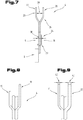
- a further embodiment variant may be provided as an alternative to the previous embodiment variant or in addition to a maximum tab spacing 38 in the axial direction between two receiving lugs 19 or 20 of a friction group 16, 17 is greater than the maximum tab spacing 39 between two receiving lugs 20 or 19 the same friction group sixteenth , 17, ie the receiving lugs 19, 20 arranged in the radial direction below or above these receiving lugs 19, 20 with the maximum lug spacing 38, with the lug spacing 37 Fig. 7
- an embodiment of this embodiment of the spring element 4 is shown in fragmentary form.
- the maximum tab spacing 39 between two second radially outer receiving tabs 20 is greater than the tab spacing 38 between two first radially inner receiving tabs 19 of the friction group 16 (in FIG Fig. 5 shown).
- the maximum tab spacing 38, 39 is in this case the largest distance between two receiving tabs 19 or 20, measured between the facing surfaces.
- the receiving lugs in the Fig. 7 shown parallel second flap portion 24 and 27 do not have but only the first oblique flap portion 23 and 26 and the helix angle is formed so that the Reibbelags nave 34, 35 or the friction linings 2, 3 rest flat on the receiving lugs 19, 20.
- the second flap portion 24 and 27 may be formed obliquely, with a helix angle of the helix angle of the first tab members 23 and 26 is different.
- the spring element 4 may be provided according to a further embodiment that at least one of the first radially inner receiving lugs 19 of in the circumferential direction 14 of the spring element body 11 or 12 juxtaposed first radially inner receiving lugs 19 is formed shorter in the radial direction, as the first radially inner receiving lugs 19 the same friction group 16 or 17th
- FIG. 8 An example of this variant is in Fig. 8 shown.
- a first radially inner receiving lug 19 in Fig. 8 shown left
- a second first radially inner receiving lug 19 in Fig. 8 shown right
- a second radially outer receiving lug 20 (in Fig. 8 not shown) made shorter in the radial direction than a second second radially outer receiving lug 20 (in Fig. 8 not shown) facing the first radially inner second receiving lug 19 in the axial direction.
- both a first radially inner and a second radially outer receiving lugs 19, 20 to be shorter in the radial direction within a friction group 16, 17 than the corresponding receiving lugs 19, which are opposite to these receiving lugs 19, 20 in the axial direction. 20.
- two receiving lugs 19 and / or receiving lugs 20 arranged side by side in the circumferential direction 14 it is possible that in the circumferential direction 14, a first radially inner receiving lug 19, then a second radially outer receiving lug 20, then subsequently a first radially inner receiving lug 19, etc. of a spring element body part 11 and / or spring element body part 12 is made shorter in the radial direction ,
- At least one of the first radially inner receiving lugs 19 in the direction of the circumferential direction 14 of the spring element body 10 has a shorter maximum lug width 40 than the other receiving lugs 19, 20, as in Fig. 6 is indicated by dashed lines.
- at least one of the second radially outer receiving lugs 20 in the direction of the circumferential direction 14 of the spring element body 10 has a shorter maximum lug width 41 than the other receiving lugs 19, 20.
- every second first radially inner receiving lug 19 can have a shorter lug width 40 and / or every second second radially outer receiving lug 20 can have a shorter lug width 41 in the circumferential direction 14.
- the first spring element body part 11 at least in the region of at least one of the receiving lugs 19 and / or receiving lugs 20 has a wall thickness 42 which is smaller to a wall thickness 43 of the second spring element body part 12, as shown in FIG Fig. 9 is shown.
- the embodiments show possible embodiments of the spring element 4 and the friction device, in particular the clutch disc 1, wherein it should be noted at this point that also various combinations of the individual embodiments are mutually possible.
Landscapes
- Engineering & Computer Science (AREA)
- General Engineering & Computer Science (AREA)
- Mechanical Engineering (AREA)
- Mechanical Operated Clutches (AREA)
- Braking Arrangements (AREA)
Claims (10)
- Élément à ressort (4) pour un dispositif à friction, plus particulièrement un disque d'embrayage (1) pour un embrayage à friction, comprenant un corps d'élément à ressort (10), qui comprend une première partie de corps d'élément à ressort (11) et une deuxième partie de corps d'élément à ressort (12), qui sont disposées l'une derrière l'autre dans la direction axiale et s'appuient partiellement l'une contre l'autre, chaque partie de corps d'élément à ressort (11, 12) comprenant des zones de logement (15), disposés les unes à côté des autres dans une direction circonférentielle (13), pour des garnitures de friction (2, 3), de façon à ce que les garnitures de friction (2, 3) soient disposées des deux côtés du corps d'élément à ressort (10) et puissent être fixés sur celui-ci, la première partie de corps d'élément à ressort (11) et la deuxième partie de corps d'élément à ressort (12) étant conçues au moins approximativement avec une forme annulaire, caractérisé en ce que, pour chaque zone de logement (15), pour les garnitures de friction (2, 3), une première patte de logement (19) et une deuxième patte de logement (20) sont prévues, la première patte de logement (19) étant disposée dans la direction radiale en dessous de la deuxième patte de logement (20), moyennant quoi, pour la fixation de chaque garniture de friction (2, 3) sur une première patte de logement radiale interne (19) et une deuxième patte de logement radiale externe (20), les deux parties de corps d'élément à ressort (11, 12) étant écartées entre elles au moins partiellement au niveau des pattes de logement (19, 20), moyennant quoi, pour la réalisation de cet écartement, les pattes de logement (19, 20) de la première partie de corps d'élément à ressort (11) sont pliées dans la direction axiale vers l'avant à partir du plan de la première partie de corps d'élément à ressort (11) et les pattes de logement (19, 20) de la deuxième partie de corps d'élément à ressort (12) sont pliées dans la direction axiale vers l'arrière à partir du plan de la deuxième partie de corps d'élément à ressort (12) et, pour cela, les premières pattes de logement radiales internes (19) comprennent, à partir d'une base (22), une partie de patte (23) oblique par rapport au plan de la première partie de corps d'élément à ressort (11) ou de la deuxième partie de corps d'élément à ressort (12), perpendiculairement à la direction axiale de l'élément à ressort (4) et une deuxième partie de patte (24), prolongeant celle-ci, qui s'étend au moins approximativement parallèle au plan de la première partie de corps d'élément à ressort (11) ou de la deuxième partie de corps d'élément à ressort (12) perpendiculairement par rapport à la direction axiale de l'élément à ressort (4) et, de manière analogue, les deuxièmes pattes de logement radiales externes (20) comprennent, à partir d'une base (25), une première partie de patte (26) oblique par rapport au plan de la première partie de corps d'élément à ressort (11) ou de la deuxième partie de corps d'élément à ressort (12), perpendiculairement à la direction axiale de l'élément à ressort (4) et une deuxième partie de patte (27), prolongeant celle-ci, qui s'étend au moins approximativement parallèle au plan de la première partie de corps d'élément à ressort (11) ou de la deuxième partie de corps d'élément à ressort (12) perpendiculairement par rapport à la direction axiale de l'élément à ressort (4) et, plus particulièrement, la première patte de logement (19) et la deuxième patte de logement (20) de chaque zone de logement (15) étant constituées, pour les garnitures de friction (2, 3) de la première partie de corps d'élément à ressort (11), de la première partie de corps d'élément à ressort (11) et la première patte de logement (19) et la deuxième patte de logement (20) de chaque zone de logement (15) étant constituées, pour les garnitures de friction (2, 3) de la deuxième partie de corps d'élément à ressort (12), de la deuxième partie de corps d'élément à ressort (12).
- Élément à ressort (4) selon la revendication 1, caractérisé en ce que les premières pattes de logement (19) de la première partie de corps d'élément à ressort (11) sont disposées chacune au moins partiellement dans un évidement (36) du premier corps d'élément à ressort (11) et/ou les premières pattes de logement (19) de la deuxième partie de corps d'élément à ressort (12) sont disposées chacun au moins partiellement dans un évidement (36) du deuxième corps d'élément à ressort (12).
- Élément à ressort (4) selon la revendication 1 ou 2, caractérisé en ce qu'au moins une des premières pattes de logement (19) sont plus courtes dans la direction radiale que les deuxièmes pattes de logement (20) dans la direction radiale et/ou au moins une des deuxièmes pattes de logement (20) est plus courte dans la direction radiale que les premières pattes de logement (19) dans la direction radiale.
- Élément à ressort (4) selon l'une des revendications 1 à 3, caractérisé en ce qu'une distance maximale (38) entre des premières pattes de logement (19), disposées l'une derrière l'autre dans la direction axiale, d'au moins une paire de premières pattes de logement (19) est inférieure ou supérieure à une distance maximale (39) entre deux deuxièmes pattes de logement (20) disposées l'une derrière l'autre dans la direction axiale.
- Élément à ressort (4) selon l'une des revendications 1 à 4, caractérisé en ce qu'au moins une des pattes de logement (19, 20) parmi des pattes de logement (19, 20) disposées les unes à côté des autres dans la direction circonférentielle (14) du corps d'élément à ressort (10) sont plus courtes dans la direction radiale que les autres pattes de logement (19, 20) dans la direction circonférentielle (14).
- Élément à ressort (4) selon l'une des revendications 1 à 5, caractérisé en ce qu'une distance maximale (38) entre des premières pattes de logement (19), disposées l'une derrière l'autre dans la direction axiale, d'au moins une paire de premières pattes de logement (19) est supérieure à la distance maximale (38) entre deux premières pattes de logement (19) des autres paires de premières pattes de logement (19) disposées les unes à côté des autres dans la direction circonférentielle (14) du corps d'élément à ressort (10) et/ou en ce qu'une distance maximale (39) entre des deuxièmes pattes de logement (20), disposées l'une derrière l'autre dans la direction axiale, d'au moins une paire d'autres pattes de logement (20) est supérieure à la distance maximale (39) entre deux deuxièmes pattes de logement (20) des autres paires de deuxièmes pattes de logement (20), disposées les unes à côtés des autres dans la direction circonférentielle (14) du corps d'élément à ressort (10).
- Élément à ressort (4) selon l'une des revendications 1 à 6, caractérisé en ce qu'au moins une des pattes de logement (19, 20) présente une largeur de patte maximale (40, 41) dans la direction circonférentielle (14) du corps d'élément à ressort (10) inférieure au reste des pattes de logement (19, 20).
- Élément à ressort (4) selon l'une des revendications 1 à 7, caractérisé en ce que les deux parties de corps d'élément à ressort (11, 12) sont chacune réalisées d'une seule pièce.
- Élément à ressort (4) selon l'une des revendications 1 à 8, caractérisé en ce que la première partie de corps d'élément à ressort (11) présente, au moins au niveau des pattes de logement (19, 20), une épaisseur de paroi (42) et en ce que la deuxième partie de corps d'élément à ressort (12) présente, au moins au niveau des pattes de logement (19, 20), une épaisseur de paroi (43), l'épaisseur de paroi (42) au niveau d'au moins une des pattes de logement (19, 20) de la première partie de corps d'élément à ressort (11) étant inférieure à l'épaisseur de paroi (43) au niveau des pattes de logement (19, 20) de la deuxième corps d'élément à ressort (12).
- Dispositif à friction, plus particulièrement disque d'embrayage (1) pour un embrayage à friction, comprenant un corps de base (5) en forme de disque avec un élément de support (8), l'élément de support (8) comprenant une circonférence externe (9), sur laquelle sont répartis plusieurs groupes de friction (16, 17), les groupes de friction (16, 17) comprenant chacun une première garniture de friction (2, 3) et une deuxième garniture de friction (2, 3) disposée derrière dans la direction axiale, les garnitures de friction (2, 3) étant reliées avec un élément à ressort (4) qui est disposé entre la première et la deuxième garnitures de friction (2, 3), le cas échéant avec l'intercalage à chaque fois d'un support de garniture de friction (34, 35), et l'élément à ressort (4) étant relié avec l'élément de support (8), caractérisé en ce que l'élément à ressort (4) est conçu selon l'une des revendications 1 à 9 et chaque garniture de friction (2, 3) est fixée sur une première patte de logement radiale interne (19) et une deuxième patte de logement radiale externe (20) de l'élément à ressort (4).
Applications Claiming Priority (2)
| Application Number | Priority Date | Filing Date | Title |
|---|---|---|---|
| ATA50241/2014A AT515594A1 (de) | 2014-04-01 | 2014-04-01 | Federelement für eine Reibvorrichtung |
| PCT/AT2015/050083 WO2015149100A2 (fr) | 2014-04-01 | 2015-03-31 | Élément ressort pour dispositif de friction |
Publications (2)
| Publication Number | Publication Date |
|---|---|
| EP3126692A2 EP3126692A2 (fr) | 2017-02-08 |
| EP3126692B1 true EP3126692B1 (fr) | 2018-04-25 |
Family
ID=53764991
Family Applications (1)
| Application Number | Title | Priority Date | Filing Date |
|---|---|---|---|
| EP15744846.5A Not-in-force EP3126692B1 (fr) | 2014-04-01 | 2015-03-31 | Élément ressort pour dispositif de friction |
Country Status (5)
| Country | Link |
|---|---|
| US (1) | US10197108B2 (fr) |
| EP (1) | EP3126692B1 (fr) |
| CN (1) | CN106164520B (fr) |
| AT (1) | AT515594A1 (fr) |
| WO (1) | WO2015149100A2 (fr) |
Families Citing this family (3)
| Publication number | Priority date | Publication date | Assignee | Title |
|---|---|---|---|---|
| AT521575B1 (de) * | 2018-08-21 | 2020-08-15 | Miba Frictec Gmbh | Reibvorrichtung |
| AT522609B1 (de) * | 2019-05-28 | 2022-06-15 | Miba Frictec Gmbh | Reibvorrichtung |
| FR3105321B1 (fr) * | 2019-12-19 | 2022-03-25 | Valeo Embrayages | Dispositif de progressivite pour disque d’embrayage a friction et disque d’embrayage a friction integrant un tel dispositif |
Family Cites Families (28)
| Publication number | Priority date | Publication date | Assignee | Title |
|---|---|---|---|---|
| US1934109A (en) * | 1928-05-14 | 1933-11-07 | Ernest E Wemp | Clutch |
| US1810360A (en) * | 1929-09-12 | 1931-06-16 | Int Motor Co | Clutch disk construction |
| US1956828A (en) * | 1931-03-02 | 1934-05-01 | Continental Motors Corp | Clutch disk |
| FR718429A (fr) * | 1931-06-09 | 1932-01-25 | Borg And Beck Company | Embrayage à friction |
| US2008169A (en) * | 1932-03-23 | 1935-07-16 | Gen Motors Corp | Clutch plate |
| GB431075A (en) * | 1933-10-27 | 1935-07-01 | Borg & Beck Co | Improvements in or relating to friction clutches |
| US2035916A (en) * | 1933-12-06 | 1936-03-31 | Raybestos Manhattan Inc | Friction clutch member |
| DE701985C (de) * | 1933-12-11 | 1941-01-28 | Borg Warner | be, insbesondere fuer Kraftfahrzeuge |
| US2101410A (en) * | 1933-12-11 | 1937-12-07 | Borg Warner | Clutch plate |
| GB473378A (en) * | 1936-08-01 | 1937-10-12 | Borg And Beck Company Ltd | Improvements in or relating to clutches |
| US2244134A (en) * | 1938-02-10 | 1941-06-03 | Thelander W Vincent | Clutch plate |
| US2308604A (en) * | 1939-06-14 | 1943-01-19 | George I Goodwin | Clutch driven plate assembly |
| DE901479C (de) * | 1948-03-24 | 1954-01-11 | Borg Warner | Kupplungsscheibe fuer Scheibenreibrungskupplungen |
| DE1210686B (de) | 1958-05-09 | 1966-02-10 | Daimler Benz Ag | Kupplungsscheibe in Kupplungen fuer insbesondere Kraftfahrzeuge |
| JPS5644295B2 (fr) * | 1971-12-31 | 1981-10-19 | ||
| DE2920095A1 (de) | 1979-05-18 | 1980-11-27 | Fichtel & Sachs Ag | Reibbelagbefestigung |
| US4278162A (en) * | 1979-06-18 | 1981-07-14 | The S. K. Wellman Corp. | Friction disc |
| US4869356A (en) * | 1988-09-20 | 1989-09-26 | Dana Corporation | Clutch disk with spring cushioned friction element |
| CA2083574C (fr) | 1991-12-27 | 2002-11-19 | Andrzej Szadkowski | Entrainement par disque, avec amortisseur |
| DE4226762C2 (de) * | 1992-08-13 | 2002-08-29 | Zf Sachs Ag | Kupplungsscheibe mit Belagfeder |
| GB2278894B (en) | 1993-05-26 | 1997-12-24 | Luk Lamellen & Kupplungsbau | Friction clutch |
| US5857551A (en) | 1996-03-19 | 1999-01-12 | Exedy Corporation | Clutch disk assembly having cushioning plates and paired friction pads riveted together |
| DE19634534A1 (de) * | 1996-08-27 | 1998-03-12 | Porsche Ag | Kupplungsscheibe für eine Kraftfahrzeug-Reibungskupplung |
| FR2782138B1 (fr) * | 1998-08-07 | 2001-03-02 | Valeo | Disque porte-garnitures pour support de garnitures de frottement, notamment pour vehicule automobile |
| DE10041216A1 (de) * | 2000-08-22 | 2002-03-07 | Daimler Chrysler Ag | Kupplungsscheibe und deren Verwendung |
| DE102004038805A1 (de) * | 2004-08-10 | 2006-02-23 | Zf Friedrichshafen Ag | Kupplungseinrichtung |
| WO2006086949A1 (fr) * | 2005-02-16 | 2006-08-24 | Luk Lamellen Und Kupplungsbau Beteiligungs Kg | Plateau d'embrayage |
| EP1896743B1 (fr) * | 2005-06-24 | 2008-11-05 | LuK Lamellen und Kupplungsbau Beteiligungs KG | Disque d'embrayage |
-
2014
- 2014-04-01 AT ATA50241/2014A patent/AT515594A1/de unknown
-
2015
- 2015-03-31 EP EP15744846.5A patent/EP3126692B1/fr not_active Not-in-force
- 2015-03-31 US US15/300,892 patent/US10197108B2/en active Active
- 2015-03-31 WO PCT/AT2015/050083 patent/WO2015149100A2/fr not_active Ceased
- 2015-03-31 CN CN201580017866.6A patent/CN106164520B/zh not_active Expired - Fee Related
Non-Patent Citations (1)
| Title |
|---|
| None * |
Also Published As
| Publication number | Publication date |
|---|---|
| WO2015149100A2 (fr) | 2015-10-08 |
| US10197108B2 (en) | 2019-02-05 |
| US20170023071A1 (en) | 2017-01-26 |
| AT515594A1 (de) | 2015-10-15 |
| CN106164520A (zh) | 2016-11-23 |
| WO2015149100A3 (fr) | 2015-12-17 |
| CN106164520B (zh) | 2019-09-27 |
| EP3126692A2 (fr) | 2017-02-08 |
Similar Documents
| Publication | Publication Date | Title |
|---|---|---|
| EP3036451B1 (fr) | Disque d'embrayage | |
| EP3164615B1 (fr) | Disque d'embrayage | |
| DE102014223308A1 (de) | Kupplungsscheibe mit Tilgereinheit | |
| EP0311844B1 (fr) | Disque d'embrayage | |
| DE102010036169A1 (de) | Kupplungsscheibe | |
| EP3126692A2 (fr) | Élément ressort pour dispositif de friction | |
| EP3036452B1 (fr) | Élément de friction | |
| DE3149218C2 (de) | Kupplungsscheibe | |
| DE2738860C3 (de) | Mit Schwingungsdämpfer versehene Kupplungsscheibe | |
| AT520092B1 (de) | Verfahren zur Herstellung eines Reibelementes | |
| EP2707624B1 (fr) | Amortisseur de vibration de torsion | |
| AT522609B1 (de) | Reibvorrichtung | |
| AT521020B1 (de) | Kupplungsscheibe | |
| DE102023107943A1 (de) | Bremsbelag | |
| DE2241884C2 (de) | Kupplungsscheibe für Reibscheibenkupplungen | |
| AT521575B1 (de) | Reibvorrichtung | |
| DE102014219621A1 (de) | Mehrfachkupplung für ein Kraftfahrzeuggetriebe | |
| DE19940507A1 (de) | Torsionsfeder, Drehschwingungsdämpfer sowie Anordnung mit einer Torsionsfeder | |
| DE102018115700A1 (de) | Kupplungsscheibe mit Reibungsvorrichtung | |
| AT520115B1 (de) | Reibvorrichtung | |
| DE102011103776A1 (de) | Kupplungsscheibe | |
| DE102016214021B4 (de) | Kupplungseinrichtung | |
| DE102014114460A1 (de) | Anordnung für eine Wellenkupplung | |
| DE102020202182A1 (de) | Torsionsschwingungsdämpfer mit Verdrehwinkelbegrenzung und Kupplungsscheibe mit Torsionsschwingungsdämpfer | |
| DE102010062492A1 (de) | Belagfeder für eine Kupplungsscheibe einer Reibungskupplung |
Legal Events
| Date | Code | Title | Description |
|---|---|---|---|
| STAA | Information on the status of an ep patent application or granted ep patent |
Free format text: STATUS: THE INTERNATIONAL PUBLICATION HAS BEEN MADE |
|
| PUAI | Public reference made under article 153(3) epc to a published international application that has entered the european phase |
Free format text: ORIGINAL CODE: 0009012 |
|
| STAA | Information on the status of an ep patent application or granted ep patent |
Free format text: STATUS: REQUEST FOR EXAMINATION WAS MADE |
|
| 17P | Request for examination filed |
Effective date: 20161028 |
|
| AK | Designated contracting states |
Kind code of ref document: A2 Designated state(s): AL AT BE BG CH CY CZ DE DK EE ES FI FR GB GR HR HU IE IS IT LI LT LU LV MC MK MT NL NO PL PT RO RS SE SI SK SM TR |
|
| AX | Request for extension of the european patent |
Extension state: BA ME |
|
| RIN1 | Information on inventor provided before grant (corrected) |
Inventor name: ASCHOFF, MICHAEL Inventor name: MUEHLEGGER, MARKUS Inventor name: BASIEWICZ, MICHAEL Inventor name: MERKEL, PHILIPP |
|
| DAV | Request for validation of the european patent (deleted) | ||
| DAX | Request for extension of the european patent (deleted) | ||
| GRAP | Despatch of communication of intention to grant a patent |
Free format text: ORIGINAL CODE: EPIDOSNIGR1 |
|
| STAA | Information on the status of an ep patent application or granted ep patent |
Free format text: STATUS: GRANT OF PATENT IS INTENDED |
|
| INTG | Intention to grant announced |
Effective date: 20171123 |
|
| GRAS | Grant fee paid |
Free format text: ORIGINAL CODE: EPIDOSNIGR3 |
|
| GRAA | (expected) grant |
Free format text: ORIGINAL CODE: 0009210 |
|
| STAA | Information on the status of an ep patent application or granted ep patent |
Free format text: STATUS: THE PATENT HAS BEEN GRANTED |
|
| AK | Designated contracting states |
Kind code of ref document: B1 Designated state(s): AL AT BE BG CH CY CZ DE DK EE ES FI FR GB GR HR HU IE IS IT LI LT LU LV MC MK MT NL NO PL PT RO RS SE SI SK SM TR |
|
| REG | Reference to a national code |
Ref country code: GB Ref legal event code: FG4D Free format text: NOT ENGLISH |
|
| REG | Reference to a national code |
Ref country code: CH Ref legal event code: EP |
|
| REG | Reference to a national code |
Ref country code: AT Ref legal event code: REF Ref document number: 993239 Country of ref document: AT Kind code of ref document: T Effective date: 20180515 |
|
| REG | Reference to a national code |
Ref country code: IE Ref legal event code: FG4D Free format text: LANGUAGE OF EP DOCUMENT: GERMAN |
|
| REG | Reference to a national code |
Ref country code: DE Ref legal event code: R096 Ref document number: 502015004046 Country of ref document: DE |
|
| REG | Reference to a national code |
Ref country code: NL Ref legal event code: MP Effective date: 20180425 |
|
| REG | Reference to a national code |
Ref country code: LT Ref legal event code: MG4D |
|
| PG25 | Lapsed in a contracting state [announced via postgrant information from national office to epo] |
Ref country code: NL Free format text: LAPSE BECAUSE OF FAILURE TO SUBMIT A TRANSLATION OF THE DESCRIPTION OR TO PAY THE FEE WITHIN THE PRESCRIBED TIME-LIMIT Effective date: 20180425 |
|
| PG25 | Lapsed in a contracting state [announced via postgrant information from national office to epo] |
Ref country code: BG Free format text: LAPSE BECAUSE OF FAILURE TO SUBMIT A TRANSLATION OF THE DESCRIPTION OR TO PAY THE FEE WITHIN THE PRESCRIBED TIME-LIMIT Effective date: 20180725 Ref country code: FI Free format text: LAPSE BECAUSE OF FAILURE TO SUBMIT A TRANSLATION OF THE DESCRIPTION OR TO PAY THE FEE WITHIN THE PRESCRIBED TIME-LIMIT Effective date: 20180425 Ref country code: NO Free format text: LAPSE BECAUSE OF FAILURE TO SUBMIT A TRANSLATION OF THE DESCRIPTION OR TO PAY THE FEE WITHIN THE PRESCRIBED TIME-LIMIT Effective date: 20180725 Ref country code: PL Free format text: LAPSE BECAUSE OF FAILURE TO SUBMIT A TRANSLATION OF THE DESCRIPTION OR TO PAY THE FEE WITHIN THE PRESCRIBED TIME-LIMIT Effective date: 20180425 Ref country code: LT Free format text: LAPSE BECAUSE OF FAILURE TO SUBMIT A TRANSLATION OF THE DESCRIPTION OR TO PAY THE FEE WITHIN THE PRESCRIBED TIME-LIMIT Effective date: 20180425 Ref country code: ES Free format text: LAPSE BECAUSE OF FAILURE TO SUBMIT A TRANSLATION OF THE DESCRIPTION OR TO PAY THE FEE WITHIN THE PRESCRIBED TIME-LIMIT Effective date: 20180425 Ref country code: SE Free format text: LAPSE BECAUSE OF FAILURE TO SUBMIT A TRANSLATION OF THE DESCRIPTION OR TO PAY THE FEE WITHIN THE PRESCRIBED TIME-LIMIT Effective date: 20180425 |
|
| PG25 | Lapsed in a contracting state [announced via postgrant information from national office to epo] |
Ref country code: LV Free format text: LAPSE BECAUSE OF FAILURE TO SUBMIT A TRANSLATION OF THE DESCRIPTION OR TO PAY THE FEE WITHIN THE PRESCRIBED TIME-LIMIT Effective date: 20180425 Ref country code: RS Free format text: LAPSE BECAUSE OF FAILURE TO SUBMIT A TRANSLATION OF THE DESCRIPTION OR TO PAY THE FEE WITHIN THE PRESCRIBED TIME-LIMIT Effective date: 20180425 Ref country code: HR Free format text: LAPSE BECAUSE OF FAILURE TO SUBMIT A TRANSLATION OF THE DESCRIPTION OR TO PAY THE FEE WITHIN THE PRESCRIBED TIME-LIMIT Effective date: 20180425 Ref country code: GR Free format text: LAPSE BECAUSE OF FAILURE TO SUBMIT A TRANSLATION OF THE DESCRIPTION OR TO PAY THE FEE WITHIN THE PRESCRIBED TIME-LIMIT Effective date: 20180726 |
|
| PG25 | Lapsed in a contracting state [announced via postgrant information from national office to epo] |
Ref country code: PT Free format text: LAPSE BECAUSE OF FAILURE TO SUBMIT A TRANSLATION OF THE DESCRIPTION OR TO PAY THE FEE WITHIN THE PRESCRIBED TIME-LIMIT Effective date: 20180827 |
|
| REG | Reference to a national code |
Ref country code: DE Ref legal event code: R097 Ref document number: 502015004046 Country of ref document: DE |
|
| PG25 | Lapsed in a contracting state [announced via postgrant information from national office to epo] |
Ref country code: EE Free format text: LAPSE BECAUSE OF FAILURE TO SUBMIT A TRANSLATION OF THE DESCRIPTION OR TO PAY THE FEE WITHIN THE PRESCRIBED TIME-LIMIT Effective date: 20180425 Ref country code: SK Free format text: LAPSE BECAUSE OF FAILURE TO SUBMIT A TRANSLATION OF THE DESCRIPTION OR TO PAY THE FEE WITHIN THE PRESCRIBED TIME-LIMIT Effective date: 20180425 Ref country code: DK Free format text: LAPSE BECAUSE OF FAILURE TO SUBMIT A TRANSLATION OF THE DESCRIPTION OR TO PAY THE FEE WITHIN THE PRESCRIBED TIME-LIMIT Effective date: 20180425 Ref country code: RO Free format text: LAPSE BECAUSE OF FAILURE TO SUBMIT A TRANSLATION OF THE DESCRIPTION OR TO PAY THE FEE WITHIN THE PRESCRIBED TIME-LIMIT Effective date: 20180425 Ref country code: CZ Free format text: LAPSE BECAUSE OF FAILURE TO SUBMIT A TRANSLATION OF THE DESCRIPTION OR TO PAY THE FEE WITHIN THE PRESCRIBED TIME-LIMIT Effective date: 20180425 |
|
| PG25 | Lapsed in a contracting state [announced via postgrant information from national office to epo] |
Ref country code: SM Free format text: LAPSE BECAUSE OF FAILURE TO SUBMIT A TRANSLATION OF THE DESCRIPTION OR TO PAY THE FEE WITHIN THE PRESCRIBED TIME-LIMIT Effective date: 20180425 |
|
| PLBE | No opposition filed within time limit |
Free format text: ORIGINAL CODE: 0009261 |
|
| STAA | Information on the status of an ep patent application or granted ep patent |
Free format text: STATUS: NO OPPOSITION FILED WITHIN TIME LIMIT |
|
| 26N | No opposition filed |
Effective date: 20190128 |
|
| REG | Reference to a national code |
Ref country code: DE Ref legal event code: R082 Ref document number: 502015004046 Country of ref document: DE Representative=s name: ABP BURGER RECHTSANWALTSGESELLSCHAFT MBH, DE |
|
| PG25 | Lapsed in a contracting state [announced via postgrant information from national office to epo] |
Ref country code: SI Free format text: LAPSE BECAUSE OF FAILURE TO SUBMIT A TRANSLATION OF THE DESCRIPTION OR TO PAY THE FEE WITHIN THE PRESCRIBED TIME-LIMIT Effective date: 20180425 |
|
| PG25 | Lapsed in a contracting state [announced via postgrant information from national office to epo] |
Ref country code: MC Free format text: LAPSE BECAUSE OF FAILURE TO SUBMIT A TRANSLATION OF THE DESCRIPTION OR TO PAY THE FEE WITHIN THE PRESCRIBED TIME-LIMIT Effective date: 20180425 |
|
| REG | Reference to a national code |
Ref country code: CH Ref legal event code: PL |
|
| PG25 | Lapsed in a contracting state [announced via postgrant information from national office to epo] |
Ref country code: LU Free format text: LAPSE BECAUSE OF NON-PAYMENT OF DUE FEES Effective date: 20190331 Ref country code: AL Free format text: LAPSE BECAUSE OF FAILURE TO SUBMIT A TRANSLATION OF THE DESCRIPTION OR TO PAY THE FEE WITHIN THE PRESCRIBED TIME-LIMIT Effective date: 20180425 |
|
| REG | Reference to a national code |
Ref country code: BE Ref legal event code: MM Effective date: 20190331 |
|
| PG25 | Lapsed in a contracting state [announced via postgrant information from national office to epo] |
Ref country code: LI Free format text: LAPSE BECAUSE OF NON-PAYMENT OF DUE FEES Effective date: 20190331 Ref country code: CH Free format text: LAPSE BECAUSE OF NON-PAYMENT OF DUE FEES Effective date: 20190331 Ref country code: IE Free format text: LAPSE BECAUSE OF NON-PAYMENT OF DUE FEES Effective date: 20190331 |
|
| PG25 | Lapsed in a contracting state [announced via postgrant information from national office to epo] |
Ref country code: BE Free format text: LAPSE BECAUSE OF NON-PAYMENT OF DUE FEES Effective date: 20190331 |
|
| PG25 | Lapsed in a contracting state [announced via postgrant information from national office to epo] |
Ref country code: TR Free format text: LAPSE BECAUSE OF FAILURE TO SUBMIT A TRANSLATION OF THE DESCRIPTION OR TO PAY THE FEE WITHIN THE PRESCRIBED TIME-LIMIT Effective date: 20180425 |
|
| PG25 | Lapsed in a contracting state [announced via postgrant information from national office to epo] |
Ref country code: MT Free format text: LAPSE BECAUSE OF FAILURE TO SUBMIT A TRANSLATION OF THE DESCRIPTION OR TO PAY THE FEE WITHIN THE PRESCRIBED TIME-LIMIT Effective date: 20180425 |
|
| REG | Reference to a national code |
Ref country code: AT Ref legal event code: MM01 Ref document number: 993239 Country of ref document: AT Kind code of ref document: T Effective date: 20200331 |
|
| PG25 | Lapsed in a contracting state [announced via postgrant information from national office to epo] |
Ref country code: CY Free format text: LAPSE BECAUSE OF FAILURE TO SUBMIT A TRANSLATION OF THE DESCRIPTION OR TO PAY THE FEE WITHIN THE PRESCRIBED TIME-LIMIT Effective date: 20180425 |
|
| PG25 | Lapsed in a contracting state [announced via postgrant information from national office to epo] |
Ref country code: IS Free format text: LAPSE BECAUSE OF FAILURE TO SUBMIT A TRANSLATION OF THE DESCRIPTION OR TO PAY THE FEE WITHIN THE PRESCRIBED TIME-LIMIT Effective date: 20180825 |
|
| PG25 | Lapsed in a contracting state [announced via postgrant information from national office to epo] |
Ref country code: HU Free format text: LAPSE BECAUSE OF FAILURE TO SUBMIT A TRANSLATION OF THE DESCRIPTION OR TO PAY THE FEE WITHIN THE PRESCRIBED TIME-LIMIT; INVALID AB INITIO Effective date: 20150331 |
|
| PG25 | Lapsed in a contracting state [announced via postgrant information from national office to epo] |
Ref country code: AT Free format text: LAPSE BECAUSE OF NON-PAYMENT OF DUE FEES Effective date: 20200331 |
|
| PG25 | Lapsed in a contracting state [announced via postgrant information from national office to epo] |
Ref country code: MK Free format text: LAPSE BECAUSE OF FAILURE TO SUBMIT A TRANSLATION OF THE DESCRIPTION OR TO PAY THE FEE WITHIN THE PRESCRIBED TIME-LIMIT Effective date: 20180425 |
|
| P01 | Opt-out of the competence of the unified patent court (upc) registered |
Effective date: 20230527 |
|
| PGFP | Annual fee paid to national office [announced via postgrant information from national office to epo] |
Ref country code: DE Payment date: 20240304 Year of fee payment: 10 Ref country code: GB Payment date: 20240304 Year of fee payment: 10 |
|
| PGFP | Annual fee paid to national office [announced via postgrant information from national office to epo] |
Ref country code: IT Payment date: 20240304 Year of fee payment: 10 Ref country code: FR Payment date: 20240304 Year of fee payment: 10 |
|
| REG | Reference to a national code |
Ref country code: DE Ref legal event code: R119 Ref document number: 502015004046 Country of ref document: DE |
|
| GBPC | Gb: european patent ceased through non-payment of renewal fee |
Effective date: 20250331 |
|
| PG25 | Lapsed in a contracting state [announced via postgrant information from national office to epo] |
Ref country code: DE Free format text: LAPSE BECAUSE OF NON-PAYMENT OF DUE FEES Effective date: 20251001 |
|
| PG25 | Lapsed in a contracting state [announced via postgrant information from national office to epo] |
Ref country code: GB Free format text: LAPSE BECAUSE OF NON-PAYMENT OF DUE FEES Effective date: 20250331 |
|
| PG25 | Lapsed in a contracting state [announced via postgrant information from national office to epo] |
Ref country code: FR Free format text: LAPSE BECAUSE OF NON-PAYMENT OF DUE FEES Effective date: 20250331 Ref country code: IT Free format text: LAPSE BECAUSE OF NON-PAYMENT OF DUE FEES Effective date: 20250331 |