EP3127514A1 - Knochenretraktionsvorrichtung und bruchverringerungssystem damit - Google Patents
Knochenretraktionsvorrichtung und bruchverringerungssystem damit Download PDFInfo
- Publication number
- EP3127514A1 EP3127514A1 EP15773253.8A EP15773253A EP3127514A1 EP 3127514 A1 EP3127514 A1 EP 3127514A1 EP 15773253 A EP15773253 A EP 15773253A EP 3127514 A1 EP3127514 A1 EP 3127514A1
- Authority
- EP
- European Patent Office
- Prior art keywords
- bone
- bone fragment
- reduction system
- traction device
- traction
- Prior art date
- Legal status (The legal status is an assumption and is not a legal conclusion. Google has not performed a legal analysis and makes no representation as to the accuracy of the status listed.)
- Granted
Links
Images






Classifications
-
- A—HUMAN NECESSITIES
- A61—MEDICAL OR VETERINARY SCIENCE; HYGIENE
- A61B—DIAGNOSIS; SURGERY; IDENTIFICATION
- A61B34/00—Computer-aided surgery; Manipulators or robots specially adapted for use in surgery
- A61B34/30—Surgical robots
-
- A—HUMAN NECESSITIES
- A61—MEDICAL OR VETERINARY SCIENCE; HYGIENE
- A61B—DIAGNOSIS; SURGERY; IDENTIFICATION
- A61B17/00—Surgical instruments, devices or methods
- A61B17/56—Surgical instruments or methods for treatment of bones or joints; Devices specially adapted therefor
- A61B17/58—Surgical instruments or methods for treatment of bones or joints; Devices specially adapted therefor for osteosynthesis, e.g. bone plates, screws or setting implements
- A61B17/60—Surgical instruments or methods for treatment of bones or joints; Devices specially adapted therefor for osteosynthesis, e.g. bone plates, screws or setting implements for external osteosynthesis, e.g. distractors, contractors
- A61B17/64—Devices extending alongside the bones to be positioned
- A61B17/6408—Devices not permitting mobility, e.g. fixed to bed, with or without means for traction or reduction
-
- A—HUMAN NECESSITIES
- A61—MEDICAL OR VETERINARY SCIENCE; HYGIENE
- A61B—DIAGNOSIS; SURGERY; IDENTIFICATION
- A61B17/00—Surgical instruments, devices or methods
- A61B17/56—Surgical instruments or methods for treatment of bones or joints; Devices specially adapted therefor
- A61B17/58—Surgical instruments or methods for treatment of bones or joints; Devices specially adapted therefor for osteosynthesis, e.g. bone plates, screws or setting implements
- A61B17/88—Osteosynthesis instruments; Methods or means for implanting or extracting internal or external fixation devices
- A61B17/8866—Osteosynthesis instruments; Methods or means for implanting or extracting internal or external fixation devices for gripping or pushing bones, e.g. approximators
-
- A—HUMAN NECESSITIES
- A61—MEDICAL OR VETERINARY SCIENCE; HYGIENE
- A61B—DIAGNOSIS; SURGERY; IDENTIFICATION
- A61B34/00—Computer-aided surgery; Manipulators or robots specially adapted for use in surgery
- A61B34/30—Surgical robots
- A61B34/35—Surgical robots for telesurgery
-
- A—HUMAN NECESSITIES
- A61—MEDICAL OR VETERINARY SCIENCE; HYGIENE
- A61B—DIAGNOSIS; SURGERY; IDENTIFICATION
- A61B90/00—Instruments, implements or accessories specially adapted for surgery or diagnosis and not covered by any of the groups A61B1/00 - A61B50/00, e.g. for luxation treatment or for protecting wound edges
- A61B90/06—Measuring instruments not otherwise provided for
- A61B2090/064—Measuring instruments not otherwise provided for for measuring force, pressure or mechanical tension
Definitions
- the present disclosure relates to a bone traction device and a fracture reduction system including the same, and more particularly, to a bone traction device used for bonding the respective fractured bone fragments of a patient and a fracture reduction system including the same.
- a surgical procedure on arm, leg, and pelvis fractures largely consists of a reduction and a fixing of bone fragments.
- Two to three surgeons generally participate in the surgical procedure.
- the reason why many surgeons are required is that there is a need to tow arm, leg, and pelvis portions (hereinafter, referred to as fractured portions) with a great force of about 200 to 400 N for the fracture reduction.
- a fracture table used only for fracture surgery for the foregoing traction has been marketed.
- the fracture table is a form in which the fractured portion is towed while fixing a foot portion, it is difficult to accurately adjust positions of bone fragments and measure a force required for traction of bone fragments, which may cause an excessive traction.
- the present disclosure provides a bone traction device that can facilitate an accurate reduction of bone fragments and be compactly manufactured because a fine adjustment of the bone fragments towed is freely performed even in a state in which a traction force is applied to fractured portions (arm, leg, and pelvis portions) of a patient at the time of directly or indirectly towing the fractured portions of the patient, and a fracture reduction system including the same.
- a bone traction device includes: a base; a support vertically disposed on the base; a traction shaft provided at the support in a perpendicular direction and driven in forward and backward directions; and a double-joint part connected to the traction shaft and bent in multiple stages with respect to a driving direction of the traction shaft.
- the double-joint part may include: a first ball joint pivotally connected to one end portion of the traction shaft; a second ball joint spaced apart from the first ball joint; a connection member interconnecting between the first and second ball joints; and a socket member pivotally connected with the second ball joint and connected to a patient.
- connection member may be formed of a metal bar or a wire having stiffness.
- the bone traction device may further include: a gripping member installed in the socket member and griping bone fragments of the patient.
- the gripping member may be a C type clamp.
- the bone traction device may further include: air boots enclosing a part of a fractured portion of the patient in a pressed state, in which the socket member may be connected to one end portion of the air boots.
- the traction shaft may include a dynamics sensor for detecting a traction force.
- the bone traction device may further include: a display electrically connected to the dynamics sensor to display the refraction force detected by the dynamics sensor.
- the traction shaft may include a fail-safe part.
- the support may be driven to be vertically elevated to set a height of the traction shaft.
- a refraction reduction system includes: a first bone fragment support part gripping a proximal bone fragment; a second bone fragment support part gripping a distal bone fragment; and a bone traction device towing a fractured portion of a patient, in which a tip portion of the bone traction device may be bent to change a position of the distal bone fragment by the second bone fragment support part.
- the bone traction device may include: a base; a traction shaft supported to the base and driven in forward and backward directions; and a double-joint part including a first ball joint pivotally connected to one end portion of the traction shaft, a second ball joint spaced apart from the first ball joint, a connection member interconnecting between the first and second ball joints; and a socket member pivotally connected with the second ball joint and connected to a patient.
- the first and second bone fragment support parts may each be provided with a pair of fixing pins; and at least one spike that guides the pair of fixing pins to be fixed to the respective bone fragments and is fixed to the respective bone fragments at a tip portion of the first and second bone fragment.
- a stopper to restrict an insertion depth of the respective fixing pins into the respective bone fragments may protrude at outer circumferences of the tip portions of the pair of fixing pins, respectively.
- the refraction reduction system may further include: a remote controller remotely controlling a driving of the bone traction device.
- the adoption of the double-joint part freely performs the fine adjustment of the bone fragments towed even in the state in which the traction force is applied to the fractured portions (arm, leg, and pelvis portions) of the patient at the time of directly or indirectly towing the fractured portions of the patient.
- the bone traction device serves only to tow the fractured portions (arm, leg, and pelvis portions) of the patient, the size of the bone traction device may be compactly kept, and as a result the bone traction device may be easily installed in the operating room.
- a fracture reduction system according to first to fourth exemplary embodiments of the present disclosure may be applied to all fractured portions besides arm and leg portions but in the present embodiment, the leg fracture will be described as an example.
- FIG. 1 is a diagram schematically illustrating a fracture reduction system according to a first exemplary embodiment of the present disclosure
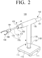
- FIG. 2 is a perspective view illustrating a bone traction device illustrated in FIG. 1
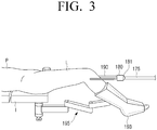
- FIG. 3 is a side view illustrating a state in which a lower bone fragment is towed by the bone traction device illustrated in FIG. 1 .
- a fracture reduction system 10 includes a bone traction device 100 towing a fractured portion of a patient P, air boots 193 enclosing a fractured portion, a first bone fragment support part 200 supporting a proximal bone fragment B1, and a second bone fragment support part 300 supporting a distal bone fragment B2.
- the bone traction device 100 directly tows the distal bone fragment B2 but has a structure in which a part of the bone traction device 100 is pivoted in a multi stage to give a degree of freedom to a second bone fragment support part 300 supporting the distal bone fragment B2 to be able to move the distal bone fragment B2 to a predetermined position. Further, the bone traction device 100 may provide a sufficient traction force (for example, 200 to 400 N) towing the distal bone fragment B2 at the time of a reduction operation while being compactly formed.
- a sufficient traction force for example, 200 to 400 N
- the bone traction device 100 as described above includes a base 110, a support 130, a traction shaft 150, a double-joint part 170, a socket member 180, and a gripping member 190.
- the base 110 is seated around a surgery bed 1 and a bottom thereof is provided with a plurality of wheels 111 for moving the base 110.
- the plurality of wheels 111 each preferably include a general locking structure (not illustrated) for selectively locking a rotation of the wheels 111.
- the support 130 is installed to be perpendicular to the base 110.
- the support 130 is configured as a general hydraulic actuator or pneumatic actuator or an electric or manual actuator to be driven up and down.
- the support 130 may include a fixed part 131 of which the lower end portion is fixed to an upper surface of the base 110 and a movable part 133 coupled to the fixed part 131.
- an upper end portion of the support 130 is integrally formed with a shaft support part 135 for supporting a traction shaft 150.
- the shaft support part 135 is disposed in approximately a perpendicular direction (horizontal direction with respect to a ground) with respect to the movable part 133.
- the traction shaft 150 is slidably installed in the shaft support part 135 to be driven in forward and backward directions.
- the traction shaft 150 may be driven by being supplied with a driving force by the general hydraulic actuator or pneumatic or electric or manual actuator connected to a back end portion 151 of the traction shaft 150.
- the traction shaft 150 may tow the distal bone fragment B2 with a predetermined traction force.
- the traction shaft 150 may be provided with a dynamics sensor (not illustrated) for detecting a traction force, in which the dynamics sensor may be, for example, a mechanical pressure sensor.
- the fracture reduction system 10 may be electrically connected to a display (not illustrated) that displays the traction force detected by the dynamics sensor in a numerical value and enables a medical team to check the refraction force.
- the traction shaft 150 may include a fail-safe part (not illustrated). Stabilizers such as the fail-safe part are to prevent soft tissues such as a nerve, a blood vessel, a muscle, and a ligament from being damaged due to the traction force provided by the traction shaft 150.
- the double-joint part 170 is pivotally connected to a tip portion of the traction shaft 150 in multiple stages with respect to a driving direction of the traction shaft 150. Even though the distal bone fragment B2 is being towed by the double-joint part 170, the second bone fragment support part 300 is given a degree of freedom to be able to move the distal bone fragment B2 to some extent.
- the distal bone fragment B2 may move to an accurate osteosynthesis position with the proximal bone fragment B1 by a fine adjustment of the second bone fragment support part 300.
- the great traction force for driving the second bone fragment support part 300 is not required, and therefore as the second bone fragment support part 300, the existing 6-axis robot may also be adopted.
- the double-joint part 170 includes a first ball joint 171, a second ball join 173, and a connection member 175.
- the first ball joint 171 is pivotally connected to a joint groove 155 formed at a tip portion 153 of the traction shaft 150.
- the joint groove 155 may have approximately a spherical shape corresponding to a shape of the first ball joint 171.
- the second ball joint 173 is pivotally connected to a joint groove 181 formed at a back end portion of the socket member 180.
- the joint groove 181 of the socket member 180 may also have approximately a spherical shape corresponding to the shape of the second ball joint 171.
- connection member 175 interconnects between the first and second ball joints 171 and 173 and may be formed of a metal bar or a metal wire having predetermined stiffness.
- the joint groove 181 formed at one end portion of the socket member 180 is pivotally connected to the second ball joint 173 as described above. Further, the other end portion of the socket member 180 is fixedly provided with the gripping member 190.
- the gripping member 190 may be formed of approximately a C-type clamp that fixes both sides of the end portion of the distal bone fragment B2. Meanwhile, to reduce the fractured portion, in some cases, a strong traction force is required, but when the ligament of the patient P is damaged, the traction through a joint may be impossible. In this case, the distal bone fragment B2 may be towed through the traction shaft 153 by directly connecting the gripping member 190 to the distal bone fragment B2
- the air boots 193 enclose approximately a knee of the fractured portion of the patient P and presses a leg with an air pressure supplied through an air supply hose 194 and fixes the leg.
- the air boots 193 serve to prevent a thrombus and serves as a foot rest.
- the air boots 193 are supported by an air boots fixing arm 195 that is formed of three links to support a self weight of a leg and has 3 degrees of freedom.
- the air boots fixing arm 195 is fixed to a portion of the surgery bed 1.
- a medical team may remotely operate the bone traction device 100 using a remote controller R.
- the medical team may tow the distal bone fragment B2 while checking a 2D or 3D perspective image without being exposed by radiation by using a radiation shielding film (not illustrated) at the time of operating the remote controller R.
- the present disclosure may improve reliability of the fracture reduction system.
- the first bone fragment support part 200 supports the proximal bone fragment B1 and the second bone fragment support part 300 supports the distal bone fragment B2.
- the first and second bone fragment support parts 200 and 300 both may be formed of a multi-axis robot having multi degrees of freedom.
- the first and second bone fragment support parts 200 and 300 may be formed of a 6 axis robot having 6 degrees of freedom.
- each end portion of the multi-axis robot is provided with a pair of fixing pins 201 and 203 and 301 and 303 and arched support frames 205 and 305 supporting them.
- the pair of fixing pins 301 and 303 is fixed to the respective bone fragments at an angle of about 60 ° or more to increase the fixing force and is preferably set to be spaced apart from each other by approximately 3 cm or more in parallel with the bone shaft C.
- a predetermined nail (not illustrated) is inserted between the bone fragments B1 and B2 or a metal plate (not illustrated) is used to fix between the bone fragments B1 and B2.
- a metal plate (not illustrated) is used to fix between the bone fragments B1 and B2.
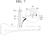
- a stopper 401b protrudes at a circumference of a tip portion 401a of a fixing pin 401, and thus an insertion depth of the fixing pin 401 into the bone fragment B2 may be easily controlled.
- a sleeve 402 is fixed to the bone fragment before the tip portion 401a of the fixing pin 401 is inserted into the bone fragment B2.
- the fixing pin 401 is inserted into the sleeve 402 to be guided to the sleeve 402.
- a tip portion of the sleeve 402 is provided with a plurality of circular spikes 402a that are fixed to the cortex of the bone fragment B2. Therefore, the sleeve 402 may firmly support the fixing pin 401.
- a hanging protrusion 401c having approximately a flange shape protrudes at a back end portion of the fixing pin 401 to prevent the sleeve 402 from being separated from the fixing pin 401.
- a fixing pin 501 and a sleeve 502 are formed to be identical with the fixing pin 401 and the sleeve 402 illustrated in FIG. 6 . However, there is a difference in a fact that a circular spike 502a formed at a tip portion of the sleeve 502 is integrally formed.
- non-explained reference numerals 501b and 501c each indicate a stopper and a hanging protrusion.
- a simple fixing apparatus 500 may be used to fix between the bone fragments B1 and B2 and may be used to disconnect the connection between the first and second bone fragment support parts 200 and 300 and then fix the bone fragments B1 and B2.
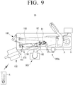
- FIG. 9 is a diagram schematically illustrating a fracture reduction system according to a second exemplary embodiment of the present disclosure.
- a fracture reduction system 20 illustrated in FIG. 9 is configured to have substantially the same configuration as the fracture reduction system 10 according to the first exemplary embodiment of the present disclosure.
- the first bone fragment support part 200a is formed of a multi-axis passive arm having a smaller size than the multi-axis robot instead of the multi-axis robot.
- the reason of applying the multi-axis passive-arm is to consider the fact that the movement of the proximal bone fragment B1 is smaller than that of the distal bone fragment B2 during the reduction surgery, which has an advantage of making the fracture reduction system cheap and ensuring a wide surgery space.
- FIG. 10 is a diagram schematically illustrating a fracture reduction system according to a third exemplary embodiment of the present disclosure.
- a fracture reduction system 30 illustrated in FIG. 10 has substantially the same configuration as the fracture reduction system 10 according to the first exemplary embodiment of the present disclosure as described above. However, there is a difference in the fact that a bone traction device 100a does not directly grip the distal bone fragment B2 but the socket member 173 is fixed to a portion of the air boots 193.
- the indirect traction of the distal bone fragment B2 through the air boots 193 may be applied to the case in which the ligament of the patient P is not damaged or a bone density of the fractured bone fragment is reduced due to osteoporosis.
- the bone traction device 100a is directly connected to the air boots 193 without the gripping member 190, it is possible to ensure a wider surgery space.
- FIG. 11 is a diagram schematically illustrating a fracture reduction system according to a fourth exemplary embodiment of the present disclosure.
- a fracture reduction system 40 illustrated in FIG. 11 is configured to have substantially the same configuration as the fracture reduction system 30 according to the third exemplary embodiment of the present disclosure.
- the first bone fragment support part 200a is formed of a multi-axis passive-arm having a smaller size than the multi-axis robot instead of the multi-axis robot.
- the fracture reduction systems 10, 20, 30, and 40 may appropriately replace the first bone fragment support parts 200 and 200a by the multi-axis robot or the multi-axis passive-arm depending on the state of the fractured portion (arm, leg, or pelvis portion) or directly tow the distal bone fragment B2 by the bone traction devices 100 and 100a or may be changed to indirectly tow the distal bone fragment B2 by towing the air boots 193.
- the present disclosure relates to a bone traction device for bonding the respective fractured bone fragments of the patient and the fracture reduction system including the same.
Landscapes
- Health & Medical Sciences (AREA)
- Surgery (AREA)
- Life Sciences & Earth Sciences (AREA)
- Engineering & Computer Science (AREA)
- Orthopedic Medicine & Surgery (AREA)
- Medical Informatics (AREA)
- Biomedical Technology (AREA)
- Heart & Thoracic Surgery (AREA)
- Nuclear Medicine, Radiotherapy & Molecular Imaging (AREA)
- Molecular Biology (AREA)
- Animal Behavior & Ethology (AREA)
- General Health & Medical Sciences (AREA)
- Public Health (AREA)
- Veterinary Medicine (AREA)
- Robotics (AREA)
- Surgical Instruments (AREA)
- Prostheses (AREA)
- Orthopedics, Nursing, And Contraception (AREA)
Applications Claiming Priority (2)
| Application Number | Priority Date | Filing Date | Title |
|---|---|---|---|
| KR1020140040001A KR101564717B1 (ko) | 2014-04-03 | 2014-04-03 | 뼈 견인장치 및 이를 포함하는 골절정복장치 |
| PCT/KR2015/003373 WO2015152679A1 (ko) | 2014-04-03 | 2015-04-03 | 뼈 견인장치 및 이를 포함하는 골절정복시스템 |
Publications (3)
| Publication Number | Publication Date |
|---|---|
| EP3127514A1 true EP3127514A1 (de) | 2017-02-08 |
| EP3127514A4 EP3127514A4 (de) | 2018-05-02 |
| EP3127514B1 EP3127514B1 (de) | 2020-11-25 |
Family
ID=54240894
Family Applications (1)
| Application Number | Title | Priority Date | Filing Date |
|---|---|---|---|
| EP15773253.8A Active EP3127514B1 (de) | 2014-04-03 | 2015-04-03 | Knochenretraktionsvorrichtung und reduktionssystem damit |
Country Status (4)
| Country | Link |
|---|---|
| EP (1) | EP3127514B1 (de) |
| KR (1) | KR101564717B1 (de) |
| CN (1) | CN106132358B (de) |
| WO (1) | WO2015152679A1 (de) |
Cited By (2)
| Publication number | Priority date | Publication date | Assignee | Title |
|---|---|---|---|---|
| US10603111B2 (en) | 2017-05-12 | 2020-03-31 | Coreline Soft Co., Ltd. | Computer assistance system and method for image-guided reduction of fracture |
| WO2020225045A1 (en) * | 2019-05-03 | 2020-11-12 | Universiteit Gent | Patient specific robotic bone implant positioning |
Families Citing this family (18)
| Publication number | Priority date | Publication date | Assignee | Title |
|---|---|---|---|---|
| GB2541177A (en) * | 2015-07-30 | 2017-02-15 | Univ Of The West Of England Bristol | Apparatus for performing fracture reduction |
| CN114948233A (zh) | 2016-09-19 | 2022-08-30 | 直观外科手术操作公司 | 用于远程可控臂的定位指示器系统和相关方法 |
| KR101915406B1 (ko) * | 2017-07-21 | 2018-11-05 | 경북대학교 산학협력단 | 견인아암 및 이를 포함하는 과부하 방지 견인장치 |
| CN107411929B (zh) * | 2017-08-17 | 2023-10-31 | 威海威高骨科手术机器人有限公司 | 下肢骨折复位装置 |
| KR102158585B1 (ko) | 2017-10-23 | 2020-09-22 | 전남대학교산학협력단 | 2축 자유도의 미세 조정이 가능한 골절 정복용 견인 장치 및 골절 정복 시스템 |
| KR102168431B1 (ko) * | 2017-10-24 | 2020-10-21 | 경북대학교 산학협력단 | 능동형 견인장치 및 이의 제어 방법 |
| CN107928956A (zh) * | 2017-11-28 | 2018-04-20 | 北京积水潭医院 | 一种基于手术床的骨折复位把持装置 |
| CN109330686B (zh) * | 2018-10-25 | 2021-06-04 | 上海大学 | 一种用于长骨骨折的机器人辅助复位系统 |
| CN111643169B (zh) * | 2020-06-23 | 2024-12-06 | 中国人民解放军总医院 | 一种组合式人体关节的复位系统 |
| CN112370135B (zh) * | 2020-11-13 | 2022-07-08 | 山东中医药大学附属医院 | 一种用于多段骨折的机器人复位系统 |
| CN112370170B (zh) * | 2020-11-13 | 2022-06-17 | 毕建平 | 一种机器人联合牵引协同骨折复位系统及其控制方法 |
| CN113768595A (zh) * | 2021-09-14 | 2021-12-10 | 四川大学华西医院 | 一种智能骨牵引工具、牵引系统及牵引方法 |
| CN114176752B (zh) * | 2021-12-15 | 2023-12-05 | 山东中医药大学附属医院 | 一种基于机器人骨折复位的夹持固定装置 |
| CN114681188A (zh) * | 2022-03-31 | 2022-07-01 | 深圳平乐骨伤科医院(深圳市坪山区中医院) | 一种运用复位机器人将中医手法复位桡骨远端骨折的方法 |
| KR20240142084A (ko) * | 2023-03-21 | 2024-09-30 | 주식회사 코렌텍 | 수술 보조 로보틱 시스템 |
| KR20250100579A (ko) | 2023-12-26 | 2025-07-03 | 주식회사 코어라인소프트 | 복잡 골절 가상 정복 프로세스를 지원하는 방법 |
| CN118000882B (zh) * | 2024-04-03 | 2024-06-04 | 吉林大学 | 一种框架式骨折复位手术机器人 |
| US12213716B1 (en) | 2024-08-30 | 2025-02-04 | Jilin University | Frame-type surgical robot for fracture reduction |
Family Cites Families (19)
| Publication number | Priority date | Publication date | Assignee | Title |
|---|---|---|---|---|
| GB1191345A (en) * | 1967-05-11 | 1970-05-13 | Ir Gnii Travmatologii I Ortope | Apparatus for Treating Fractures of Bones of the Leg |
| NL9101054A (nl) * | 1991-06-18 | 1993-01-18 | Breunis Van Den Brink | Bot-fixatie inrichting. |
| KR20000011134A (ko) * | 1996-05-15 | 2000-02-25 | 인드래니 머캐르지 | 정위 수술 방법 및 장치 |
| KR20010065553A (ko) * | 1999-12-29 | 2001-07-11 | 강석용 | 정형외과용 골절인장 및 복원장치 |
| KR100391252B1 (ko) | 2001-02-28 | 2003-07-12 | 유앤아이 주식회사 | 골절 정복 장치 |
| CN2487346Y (zh) * | 2001-03-21 | 2002-04-24 | 王端焱 | 近关节端多功能骨外固定器 |
| US6895969B2 (en) * | 2003-02-06 | 2005-05-24 | Roger J. Malcolm | Orthopedic traction device |
| KR200335336Y1 (ko) | 2003-08-29 | 2003-12-06 | 구본희 | 의료용 클램프 |
| RU2263490C2 (ru) * | 2004-01-22 | 2005-11-10 | МУЗ ЦРБ Промышленновского района Кемеровской области | Устройство для вытяжения нижней конечности |
| GB0422710D0 (en) * | 2004-10-13 | 2004-11-17 | Biocomposites Ltd | Surgical apparatus |
| EP1931298B1 (de) * | 2005-08-10 | 2017-05-31 | Mizuho Orthopedic Systems, Inc. | Patiententisch mit gesteuerter bewegung |
| EP2271272B1 (de) * | 2008-04-16 | 2014-04-02 | Synthes GmbH | Vorrichtung zur verwendung bei der neupositionierung von knochenteilen auf einem frakturtisch |
| IT1391711B1 (it) * | 2008-09-16 | 2012-01-27 | Orthofix Srl | Dispositivo ortopedico per correggere deformazioni di ossa lunghe |
| RU2541754C2 (ru) * | 2009-05-27 | 2015-02-20 | Зинтес Гмбх | Устройство "роботизированная рука" |
| CN201624764U (zh) * | 2010-01-29 | 2010-11-10 | 王卫国 | 骨科外固定装置 |
| CN102283731A (zh) * | 2011-07-06 | 2011-12-21 | 于志国 | 便携组合式整骨机 |
| TR201202175A2 (tr) * | 2012-02-27 | 2012-09-21 | Tam�� Otogaz Sanay� T�C. Ve M�H. H�Z. �Th. �Hr. Ltd. �T�. | Kemik kırıkları için bir sabitleme robotu. |
| CN103505275B (zh) * | 2013-09-09 | 2016-08-17 | 中国人民解放军第四军医大学 | 一种长骨骨折智能复位系统 |
| CN103690183B (zh) * | 2014-01-14 | 2017-01-04 | 四川聚能核技术工程有限公司 | 四肢骨折复位系统 |
-
2014
- 2014-04-03 KR KR1020140040001A patent/KR101564717B1/ko active Active
-
2015
- 2015-04-03 CN CN201580017466.5A patent/CN106132358B/zh active Active
- 2015-04-03 EP EP15773253.8A patent/EP3127514B1/de active Active
- 2015-04-03 WO PCT/KR2015/003373 patent/WO2015152679A1/ko not_active Ceased
Cited By (4)
| Publication number | Priority date | Publication date | Assignee | Title |
|---|---|---|---|---|
| US10603111B2 (en) | 2017-05-12 | 2020-03-31 | Coreline Soft Co., Ltd. | Computer assistance system and method for image-guided reduction of fracture |
| WO2020225045A1 (en) * | 2019-05-03 | 2020-11-12 | Universiteit Gent | Patient specific robotic bone implant positioning |
| US12408999B2 (en) | 2019-05-03 | 2025-09-09 | Universiteit Gent | Patient specific robotic bone implant positioning |
| AU2020269212B2 (en) * | 2019-05-03 | 2025-12-04 | Universiteit Gent | Patient specific robotic bone implant positioning |
Also Published As
| Publication number | Publication date |
|---|---|
| WO2015152679A1 (ko) | 2015-10-08 |
| EP3127514A4 (de) | 2018-05-02 |
| KR101564717B1 (ko) | 2015-11-02 |
| CN106132358B (zh) | 2019-03-19 |
| CN106132358A (zh) | 2016-11-16 |
| EP3127514B1 (de) | 2020-11-25 |
| KR20150115267A (ko) | 2015-10-14 |
Similar Documents
| Publication | Publication Date | Title |
|---|---|---|
| EP3127514B1 (de) | Knochenretraktionsvorrichtung und reduktionssystem damit | |
| US12390235B2 (en) | Surgical system for cutting an anatomical structure according to at least one target plane | |
| US12539181B2 (en) | Surgical robotic system | |
| JP6905036B2 (ja) | ドリルガイド固定具、頭蓋挿入固定具、および関連する方法およびロボットシステム | |
| EP3793451B1 (de) | Chirurgisches system zum schneiden einer anatomischen struktur gemäss mindestens einer zielebene | |
| US11998283B2 (en) | System for guiding a surgical tool relative to a target axis in spine surgery | |
| JP7065593B2 (ja) | 多軸力及びモーメントフィードバックを使用した外科用ツール挿入ためのシステム及び方法 | |
| JP7019658B2 (ja) | 追跡マーカーを備えた手術用ロボットオートメーション | |
| CN108392271A (zh) | 骨科操作系统及其控制方法 | |
| KR20120028889A (ko) | 로봇 아암 | |
| US10478362B2 (en) | Device for repositioning bone fracture fragments | |
| CN114366294A (zh) | 固定装置 |
Legal Events
| Date | Code | Title | Description |
|---|---|---|---|
| STAA | Information on the status of an ep patent application or granted ep patent |
Free format text: STATUS: THE INTERNATIONAL PUBLICATION HAS BEEN MADE |
|
| PUAI | Public reference made under article 153(3) epc to a published international application that has entered the european phase |
Free format text: ORIGINAL CODE: 0009012 |
|
| STAA | Information on the status of an ep patent application or granted ep patent |
Free format text: STATUS: REQUEST FOR EXAMINATION WAS MADE |
|
| 17P | Request for examination filed |
Effective date: 20161102 |
|
| AK | Designated contracting states |
Kind code of ref document: A1 Designated state(s): AL AT BE BG CH CY CZ DE DK EE ES FI FR GB GR HR HU IE IS IT LI LT LU LV MC MK MT NL NO PL PT RO RS SE SI SK SM TR |
|
| AX | Request for extension of the european patent |
Extension state: BA ME |
|
| DAV | Request for validation of the european patent (deleted) | ||
| DAX | Request for extension of the european patent (deleted) | ||
| RIC1 | Information provided on ipc code assigned before grant |
Ipc: A61B 17/64 20060101ALI20171103BHEP Ipc: A61B 34/35 20160101ALI20171103BHEP Ipc: A61B 34/30 20160101ALI20171103BHEP Ipc: A61B 17/88 20060101AFI20171103BHEP Ipc: A61F 5/04 20060101ALN20171103BHEP |
|
| A4 | Supplementary search report drawn up and despatched |
Effective date: 20180329 |
|
| RIC1 | Information provided on ipc code assigned before grant |
Ipc: A61B 17/88 20060101AFI20180323BHEP Ipc: A61B 34/35 20160101ALI20180323BHEP Ipc: A61F 5/04 20060101ALN20180323BHEP Ipc: A61B 34/30 20160101ALI20180323BHEP Ipc: A61B 17/64 20060101ALI20180323BHEP |
|
| REG | Reference to a national code |
Ref country code: DE Ref legal event code: R079 Ref document number: 602015062557 Country of ref document: DE Free format text: PREVIOUS MAIN CLASS: A61F0005042000 Ipc: A61B0017880000 |
|
| RIC1 | Information provided on ipc code assigned before grant |
Ipc: A61B 17/88 20060101AFI20200416BHEP Ipc: A61B 34/35 20160101ALI20200416BHEP Ipc: A61B 17/64 20060101ALI20200416BHEP Ipc: A61F 5/04 20060101ALN20200416BHEP Ipc: A61B 34/30 20160101ALI20200416BHEP |
|
| GRAP | Despatch of communication of intention to grant a patent |
Free format text: ORIGINAL CODE: EPIDOSNIGR1 |
|
| STAA | Information on the status of an ep patent application or granted ep patent |
Free format text: STATUS: GRANT OF PATENT IS INTENDED |
|
| INTG | Intention to grant announced |
Effective date: 20200617 |
|
| GRAS | Grant fee paid |
Free format text: ORIGINAL CODE: EPIDOSNIGR3 |
|
| GRAA | (expected) grant |
Free format text: ORIGINAL CODE: 0009210 |
|
| STAA | Information on the status of an ep patent application or granted ep patent |
Free format text: STATUS: THE PATENT HAS BEEN GRANTED |
|
| AK | Designated contracting states |
Kind code of ref document: B1 Designated state(s): AL AT BE BG CH CY CZ DE DK EE ES FI FR GB GR HR HU IE IS IT LI LT LU LV MC MK MT NL NO PL PT RO RS SE SI SK SM TR |
|
| REG | Reference to a national code |
Ref country code: GB Ref legal event code: FG4D |
|
| REG | Reference to a national code |
Ref country code: CH Ref legal event code: EP |
|
| REG | Reference to a national code |
Ref country code: AT Ref legal event code: REF Ref document number: 1337382 Country of ref document: AT Kind code of ref document: T Effective date: 20201215 |
|
| REG | Reference to a national code |
Ref country code: DE Ref legal event code: R096 Ref document number: 602015062557 Country of ref document: DE |
|
| REG | Reference to a national code |
Ref country code: IE Ref legal event code: FG4D |
|
| REG | Reference to a national code |
Ref country code: AT Ref legal event code: MK05 Ref document number: 1337382 Country of ref document: AT Kind code of ref document: T Effective date: 20201125 |
|
| REG | Reference to a national code |
Ref country code: NL Ref legal event code: MP Effective date: 20201125 |
|
| PG25 | Lapsed in a contracting state [announced via postgrant information from national office to epo] |
Ref country code: GR Free format text: LAPSE BECAUSE OF FAILURE TO SUBMIT A TRANSLATION OF THE DESCRIPTION OR TO PAY THE FEE WITHIN THE PRESCRIBED TIME-LIMIT Effective date: 20210226 Ref country code: NO Free format text: LAPSE BECAUSE OF FAILURE TO SUBMIT A TRANSLATION OF THE DESCRIPTION OR TO PAY THE FEE WITHIN THE PRESCRIBED TIME-LIMIT Effective date: 20210225 Ref country code: FI Free format text: LAPSE BECAUSE OF FAILURE TO SUBMIT A TRANSLATION OF THE DESCRIPTION OR TO PAY THE FEE WITHIN THE PRESCRIBED TIME-LIMIT Effective date: 20201125 Ref country code: PT Free format text: LAPSE BECAUSE OF FAILURE TO SUBMIT A TRANSLATION OF THE DESCRIPTION OR TO PAY THE FEE WITHIN THE PRESCRIBED TIME-LIMIT Effective date: 20210325 Ref country code: RS Free format text: LAPSE BECAUSE OF FAILURE TO SUBMIT A TRANSLATION OF THE DESCRIPTION OR TO PAY THE FEE WITHIN THE PRESCRIBED TIME-LIMIT Effective date: 20201125 |
|
| PG25 | Lapsed in a contracting state [announced via postgrant information from national office to epo] |
Ref country code: BG Free format text: LAPSE BECAUSE OF FAILURE TO SUBMIT A TRANSLATION OF THE DESCRIPTION OR TO PAY THE FEE WITHIN THE PRESCRIBED TIME-LIMIT Effective date: 20210225 Ref country code: AT Free format text: LAPSE BECAUSE OF FAILURE TO SUBMIT A TRANSLATION OF THE DESCRIPTION OR TO PAY THE FEE WITHIN THE PRESCRIBED TIME-LIMIT Effective date: 20201125 Ref country code: LV Free format text: LAPSE BECAUSE OF FAILURE TO SUBMIT A TRANSLATION OF THE DESCRIPTION OR TO PAY THE FEE WITHIN THE PRESCRIBED TIME-LIMIT Effective date: 20201125 Ref country code: SE Free format text: LAPSE BECAUSE OF FAILURE TO SUBMIT A TRANSLATION OF THE DESCRIPTION OR TO PAY THE FEE WITHIN THE PRESCRIBED TIME-LIMIT Effective date: 20201125 Ref country code: IS Free format text: LAPSE BECAUSE OF FAILURE TO SUBMIT A TRANSLATION OF THE DESCRIPTION OR TO PAY THE FEE WITHIN THE PRESCRIBED TIME-LIMIT Effective date: 20210325 Ref country code: PL Free format text: LAPSE BECAUSE OF FAILURE TO SUBMIT A TRANSLATION OF THE DESCRIPTION OR TO PAY THE FEE WITHIN THE PRESCRIBED TIME-LIMIT Effective date: 20201125 |
|
| REG | Reference to a national code |
Ref country code: LT Ref legal event code: MG9D |
|
| PG25 | Lapsed in a contracting state [announced via postgrant information from national office to epo] |
Ref country code: HR Free format text: LAPSE BECAUSE OF FAILURE TO SUBMIT A TRANSLATION OF THE DESCRIPTION OR TO PAY THE FEE WITHIN THE PRESCRIBED TIME-LIMIT Effective date: 20201125 |
|
| PG25 | Lapsed in a contracting state [announced via postgrant information from national office to epo] |
Ref country code: LT Free format text: LAPSE BECAUSE OF FAILURE TO SUBMIT A TRANSLATION OF THE DESCRIPTION OR TO PAY THE FEE WITHIN THE PRESCRIBED TIME-LIMIT Effective date: 20201125 Ref country code: SK Free format text: LAPSE BECAUSE OF FAILURE TO SUBMIT A TRANSLATION OF THE DESCRIPTION OR TO PAY THE FEE WITHIN THE PRESCRIBED TIME-LIMIT Effective date: 20201125 Ref country code: RO Free format text: LAPSE BECAUSE OF FAILURE TO SUBMIT A TRANSLATION OF THE DESCRIPTION OR TO PAY THE FEE WITHIN THE PRESCRIBED TIME-LIMIT Effective date: 20201125 Ref country code: CZ Free format text: LAPSE BECAUSE OF FAILURE TO SUBMIT A TRANSLATION OF THE DESCRIPTION OR TO PAY THE FEE WITHIN THE PRESCRIBED TIME-LIMIT Effective date: 20201125 Ref country code: EE Free format text: LAPSE BECAUSE OF FAILURE TO SUBMIT A TRANSLATION OF THE DESCRIPTION OR TO PAY THE FEE WITHIN THE PRESCRIBED TIME-LIMIT Effective date: 20201125 Ref country code: SM Free format text: LAPSE BECAUSE OF FAILURE TO SUBMIT A TRANSLATION OF THE DESCRIPTION OR TO PAY THE FEE WITHIN THE PRESCRIBED TIME-LIMIT Effective date: 20201125 |
|
| REG | Reference to a national code |
Ref country code: DE Ref legal event code: R097 Ref document number: 602015062557 Country of ref document: DE |
|
| PG25 | Lapsed in a contracting state [announced via postgrant information from national office to epo] |
Ref country code: DK Free format text: LAPSE BECAUSE OF FAILURE TO SUBMIT A TRANSLATION OF THE DESCRIPTION OR TO PAY THE FEE WITHIN THE PRESCRIBED TIME-LIMIT Effective date: 20201125 |
|
| PLBE | No opposition filed within time limit |
Free format text: ORIGINAL CODE: 0009261 |
|
| STAA | Information on the status of an ep patent application or granted ep patent |
Free format text: STATUS: NO OPPOSITION FILED WITHIN TIME LIMIT |
|
| PG25 | Lapsed in a contracting state [announced via postgrant information from national office to epo] |
Ref country code: IT Free format text: LAPSE BECAUSE OF FAILURE TO SUBMIT A TRANSLATION OF THE DESCRIPTION OR TO PAY THE FEE WITHIN THE PRESCRIBED TIME-LIMIT Effective date: 20201125 Ref country code: AL Free format text: LAPSE BECAUSE OF FAILURE TO SUBMIT A TRANSLATION OF THE DESCRIPTION OR TO PAY THE FEE WITHIN THE PRESCRIBED TIME-LIMIT Effective date: 20201125 Ref country code: NL Free format text: LAPSE BECAUSE OF FAILURE TO SUBMIT A TRANSLATION OF THE DESCRIPTION OR TO PAY THE FEE WITHIN THE PRESCRIBED TIME-LIMIT Effective date: 20201125 |
|
| 26N | No opposition filed |
Effective date: 20210826 |
|
| PG25 | Lapsed in a contracting state [announced via postgrant information from national office to epo] |
Ref country code: MC Free format text: LAPSE BECAUSE OF FAILURE TO SUBMIT A TRANSLATION OF THE DESCRIPTION OR TO PAY THE FEE WITHIN THE PRESCRIBED TIME-LIMIT Effective date: 20201125 Ref country code: ES Free format text: LAPSE BECAUSE OF FAILURE TO SUBMIT A TRANSLATION OF THE DESCRIPTION OR TO PAY THE FEE WITHIN THE PRESCRIBED TIME-LIMIT Effective date: 20201125 Ref country code: SI Free format text: LAPSE BECAUSE OF FAILURE TO SUBMIT A TRANSLATION OF THE DESCRIPTION OR TO PAY THE FEE WITHIN THE PRESCRIBED TIME-LIMIT Effective date: 20201125 |
|
| GBPC | Gb: european patent ceased through non-payment of renewal fee |
Effective date: 20210403 |
|
| PG25 | Lapsed in a contracting state [announced via postgrant information from national office to epo] |
Ref country code: LU Free format text: LAPSE BECAUSE OF NON-PAYMENT OF DUE FEES Effective date: 20210403 |
|
| REG | Reference to a national code |
Ref country code: BE Ref legal event code: MM Effective date: 20210430 |
|
| PG25 | Lapsed in a contracting state [announced via postgrant information from national office to epo] |
Ref country code: CH Free format text: LAPSE BECAUSE OF NON-PAYMENT OF DUE FEES Effective date: 20210430 Ref country code: LI Free format text: LAPSE BECAUSE OF NON-PAYMENT OF DUE FEES Effective date: 20210430 Ref country code: GB Free format text: LAPSE BECAUSE OF NON-PAYMENT OF DUE FEES Effective date: 20210403 |
|
| PG25 | Lapsed in a contracting state [announced via postgrant information from national office to epo] |
Ref country code: IE Free format text: LAPSE BECAUSE OF NON-PAYMENT OF DUE FEES Effective date: 20210403 |
|
| PG25 | Lapsed in a contracting state [announced via postgrant information from national office to epo] |
Ref country code: IS Free format text: LAPSE BECAUSE OF FAILURE TO SUBMIT A TRANSLATION OF THE DESCRIPTION OR TO PAY THE FEE WITHIN THE PRESCRIBED TIME-LIMIT Effective date: 20210325 |
|
| PG25 | Lapsed in a contracting state [announced via postgrant information from national office to epo] |
Ref country code: BE Free format text: LAPSE BECAUSE OF NON-PAYMENT OF DUE FEES Effective date: 20210430 |
|
| PG25 | Lapsed in a contracting state [announced via postgrant information from national office to epo] |
Ref country code: HU Free format text: LAPSE BECAUSE OF FAILURE TO SUBMIT A TRANSLATION OF THE DESCRIPTION OR TO PAY THE FEE WITHIN THE PRESCRIBED TIME-LIMIT; INVALID AB INITIO Effective date: 20150403 |
|
| PG25 | Lapsed in a contracting state [announced via postgrant information from national office to epo] |
Ref country code: CY Free format text: LAPSE BECAUSE OF FAILURE TO SUBMIT A TRANSLATION OF THE DESCRIPTION OR TO PAY THE FEE WITHIN THE PRESCRIBED TIME-LIMIT Effective date: 20201125 |
|
| PG25 | Lapsed in a contracting state [announced via postgrant information from national office to epo] |
Ref country code: MK Free format text: LAPSE BECAUSE OF FAILURE TO SUBMIT A TRANSLATION OF THE DESCRIPTION OR TO PAY THE FEE WITHIN THE PRESCRIBED TIME-LIMIT Effective date: 20201125 |
|
| PG25 | Lapsed in a contracting state [announced via postgrant information from national office to epo] |
Ref country code: MT Free format text: LAPSE BECAUSE OF FAILURE TO SUBMIT A TRANSLATION OF THE DESCRIPTION OR TO PAY THE FEE WITHIN THE PRESCRIBED TIME-LIMIT Effective date: 20201125 |
|
| PGFP | Annual fee paid to national office [announced via postgrant information from national office to epo] |
Ref country code: DE Payment date: 20250402 Year of fee payment: 11 |
|
| PG25 | Lapsed in a contracting state [announced via postgrant information from national office to epo] |
Ref country code: TR Free format text: LAPSE BECAUSE OF FAILURE TO SUBMIT A TRANSLATION OF THE DESCRIPTION OR TO PAY THE FEE WITHIN THE PRESCRIBED TIME-LIMIT Effective date: 20201125 |
|
| PGFP | Annual fee paid to national office [announced via postgrant information from national office to epo] |
Ref country code: FR Payment date: 20260326 Year of fee payment: 12 |